Abstract
Low-volume manufacturing remains a challenge, especially for parts that need to be injection-molded. Freeform injection molding (FIM) is a novel method that combines elements from direct additive manufacturing (DAM) and injection molding (IM) to resolve some of the challenges seen in low-volume injection molding. In this study, we use a design science approach to explore the suitability of FIM for the manufacturing of low volume injection-molded parts. We provide an overview of the benefits and limitations of traditional IM and discuss how DAM and indirect additive manufacturing (IAM) methods, such as soft tooling and FIM, can address some of the existing drawbacks of IM for short series production. A set of different parts was identified and assessed using a design science-based approach to demonstrate how to incubate FIM as a solution to address the challenges faced in short series production with IM. This initial process innovation was followed by solution refinement, involving the optimization of the FIM processes. Finally, a “cross-case” analysis was conducted using the framework of context, intervention, mechanism and outcomes to generate insights about the generalizability of the results. It is concluded that FIM combines the short lead-times, low start-up costs and design freedom of DAM with the versatility and scalability of IM to allow manufacturers to bring low volume products to the market faster, more cheaply and with lower risk, and to maintain the relevance of these products through easy customization and adaptations once they have been launched.
1. Introduction
Injection molding (IM) is a widely used production technology, which is very cost effective for higher volumes of parts. For low volume production, e.g., spare parts, direct additive manufacturing (DAM) technologies such as material jetting, powder bed fusion, vat photopolymerization have been proposed as more viable options [1,2]. However, DAM has multiple limitations, including: a slow process speed; poor scalability; poor dimensional accuracy compared to conventional processes; rough surface finish [3]; problems with process predictability and repeatability [4]; restricted choice of materials [5]; insufficient material properties; difficulties with material removal; high process costs; and high energy intensity [6,7]. In particular, manufacturers find it difficult to justify DAM as a direct alternative for injection molded parts, since performance requirements are often impossible to meet with DAM.
Although several studies have been conducted regarding the suitability of IM for high volume part manufacturing [8] and how DAM can address some of the drawbacks of IM for low volume production [2], there are very limited studies regarding the suitability of hybrid manufacturing approaches such as indirect additive manufacturing (IAM) [9] for short series production. Printed soft tooling (PST) and freeform injection molding (FIM) are two IAM techniques which can address some of the drawbacks of both IM and DAM for low volume production. To our knowledge, there are no systematic studies evaluating the suitability of FIM across different applications.
Accordingly, the objective of this study is to evaluate the suitability of PST and FIM for the short series production of injection-molded components. To fulfil the objectives of this study, we chose three different contrasting parts at three different positions in the product lifecycle—one used for a new product, one used for improving a product and another to be used as a spare part—to evaluate the suitability of FIM using a design science approach. We review the technical and economic aspects of all potential manufacturing alternatives to low volume manufacturing and not only focused on DAM [10,11,12]. We follow a systematic approach and undergo multiple iterations to implement FIM as the solution to produce the parts. The contribution of this research lies in systematically evaluating the suitability of FIM for different types of parts using a design science approach.
2. Literature Review
The conducted literature review about the benefits and limitations of IM, DAM and IAM listed in this section, will be used as a foundation for examining the suitability of FIM as an efficient manufacturing method for short series production in the next sections. As the literature about FIM is scares [13], there is a need to address the gaps in the academic literature regarding FIM and the positioning of FIM compared to IM and DAM.
2.1. Benefits and Limitations of IM
IM is one of the traditional manufacturing technologies, which is very cost effective for high volume production and well known for the precision of manufacturing products with high levels of details. IM is a cyclic process of rapid mold filling, followed by cooling and ejection. The cost-efficiency of the IM process is highly dependent on the molding cycle time [8] and on the distribution of high initial investments over a large number of components. A wide range of materials, including thermoplastic polymers, thermoplastic elastomers as well as a number of non-plastic materials can be used as feedstock. However, the IM process parameters need to be adjusted according to the material specifications [14].
The IM process has six main steps: (1) Preparation and loading of the feedstock into the injection molding machine, (2) Plastification and metering, (3) Injection and packing, (4) Cooling and solidification, (5) Mold opening, (6) Ejection. Recently, some injection molding machines have been produced that are also capable of molding parts that are comprised of different materials (multi-shot IM machines). A good example is the toothbrush, which is made of different plastic types with different hardness values. The multi-shot IM machines contain separate injection barrels for each material.
The lead-time and costs of mold tool manufacturing are often challenging for low volume production, where tooling investments may be difficult to recover due to the low number of components produced and sold. Moreover, the design freedom of injection molded parts is limited due to the fact that the molded parts need to be ejected from a rigid machined mold tool [15]. It should also be noted that in IM-based production, different faults such as warpage, bubbles, sink marks, brittles, cracks, and burn marks may occur [16]. By the careful adjustment of the IM parameters, such as melting temperatures, injection packing/back/holding/ejection pressure, cooling time, injection and screw speeds, we can eliminate or minimize the IM faults to a high extent. A summary of the main benefits and limitations of IM can be seen in Table 1.

Table 1.
Comparison of injection molding, direct and indirect additive manufacturing.
2.2. Benefits and Limitations of DAM
DAM, also referred to as 3D printing, is a layer-by-layer manufacturing technique to produce complex geometries directly from a digital model [12,17]. DAM has a wide range of applications, but the three areas of rapid prototyping, rapid tooling and end component manufacturing are the main applications of DAM [18]. Very briefly, the DAM process starts with a model created in a computer-aided design (CAD) software or three-dimensional scanned object that is sliced into many layers by using a slicing software. Several studies have been conducted regarding the process and design framework for DAM [19,20]. The number of layers depends on the desired printing resolution. During the printing process, each layer is deposited and solidified by means of an energy resource to create the printed part [21]. DAM is categorized into seven broad categories [22], as can be seen in Table 1. All seven categories have been commercialized and are being utilized for the manufacturing of complex geometries [23]. The potential benefits of DAM have already been studied by researchers [24,25,26]. Some of the most important benefits of DAM are: (1) Design freedom [27], (2) Short lead times [28], (3) Low start up-costs [29]. Although DAM with shorter lead times and decreased total production costs may be considered as an alternative to the traditional manufacturing technologies, it has some limitations which challenge the use of DAM as a manufacturing method even for short series productions [10,26,30]. Some of these challenges are: (1) Limits on the part size [31], (2) Anisotropic mechanical properties [32,33], (3) Slow process speed and limited scalability [34], (4) Poor dimensional accuracy [35], (5) Unpredictability and unrepeatability [36], (6) Restricted choice of materials [37], (7) Insufficient material properties [37], (8) High process costs [38], (9) High energy intensity [38]. The main benefits and limitations of DAM are summarized in Table 1.
2.3. Benefits and Limitations of IAM
IAM combines additive manufacturing (AM) and IM to merge key benefits from AM and IM. The IAM is as old as DAM and few studies have shown its advantages, such as scalability and relatively inexpensive manufacturing costs [40]. Material choice in IAM is highly flexible and a wide range of materials can be injected into the printed molds [41]. There are two main IAM technologies: 3D printed injection mold (3DPIM), which is also known as “printed soft tools” and FIM.
2.3.1. Printed Soft Tooling (PST)
Printed soft tools are mostly produced by Polyjet or Stereolithography (SLA) printing techniques due to the high level of accuracy and good surface finish (Table 1). Printed soft tools are designed as split tools (the same as traditional mold tools). They can mitigate the prolonged lead-time and high costs associated with the design and manufacturing of mold tools. It has been shown that printed soft tools allow for reductions in tooling costs of 80–90% and a 60–70% tooling lead-time reduction, when compared with a conventionally machined tool [9]. The lifetimes of the printed soft tools are limited due to the reduced wear resistance of printed tooling materials, and due to thermal shock which will result in propagation of micro-cracks and failure [42,43,44]. Therefore, soft tools can only be used for the production of a limited number of polymer parts by IM [45]. Another limiting factor regarding soft tools is that the mold tools are not temperature and pressure resistant and therefore, engineering materials cannot be injected/processed. Cooling time in soft tooling process using conventional mold materials is normally high [46], as the printed tooling needs to cool before each injection. In the following sub-section, FIM will be described and it will be discussed how FIM can address some of the drawbacks of the PST listed in Table 1.
2.3.2. FIM
FIM (Figure 1), an IAM technology, is a patent-pending concept, introduced by the Danish company AddiFab. FIM is based on the use of single-use sacrificial closed-cavity mold inserts that are made with a patent-pending soluble polymer (Figure 1a). The FIM mold inserts are printed by a direct light processing (DLP) machine in a patent-pending resin (IM 2.0 GP). The composition of IM 2.0 GP cannot be revealed due to confidentiality. The FIM mold basically consists of a block of solidified resin with an internal cavity with the geometry of the desired part (Figure 1d).
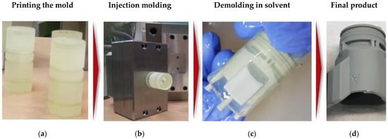
Figure 1.
(a) Printed cavity with AddiFab direct light processing (DLP) printer; (b) Inserting the printed mold in the injection tool; (c) Demolding the molded part in the solvent; (d) Final part.
The high thermal and mechanical strength of the IM 2.0 GP and the single-shot nature of FIM allows the creation of molds that are usable with the entire range of thermoplastic feedstocks. The solubility of the FIM molds allows the design freedom from 3D-printing to be transferred to the domain of injection molding. In this way, FIM can alleviate the shortcomings of both AM and IM by additively manufacturing low cost mold inserts of any complexity, which can then be used for producing low volume injection molded parts. FIM thus combines the short lead-times, low start-up costs and design freedom of AM with the versatility and scalability of IM. One of the challenges of FIM was the relatively time-consuming demolding process (Figure 1c), which has now been addressed by using hot solvent vat. The hot solvent may affect the injection-molded parts during demolding, especially where the injection-molded parts are to be made of polycarbonate (PC), polybutylene terephthalate (PBT) or polyethylene terephthalate (PET). However, these are the only three materials that have so far been identified as representing challenges in the FIM process. The overview of the FIM process chain can be seen in Figure 2.
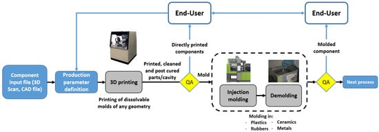
Figure 2.
High-level view of FIM process chain.
3. Challenges that can be addressed by FIM
3.1. Material Diversity and Properties
Although printers are available for the processing of a range of engineering materials (various metals, thermoplastics, elastomeric materials and ceramics) [47], the selection of materials within each of these material categories is very limited. It is costly and time-consuming to adapt a material for 3D-printing, and a wide range of materials are impossible to 3D-print due to thermal, chemical or mechanical barriers. FIM—which is based on printed, sacrificial tooling—can process the entire range of granulates made available by the injection molding industry, and this is how FIM benefits from the material diversity as the most important advantage of IM. Another DAM challenge is the anisotropic mechanical properties of the printed parts that is caused by the layer-wise build-up. Some of the material properties of parts made by DAM such as strength, strain, stiffness, ductility, electrical and thermal conductivity are highly affected by the printing direction [47,48]. Therefore, several mechanical tests are required in order to qualify the printed parts to be used as substitutes for injection-molded parts in a range of applications. As FIM uses traditional IM, the manufactured parts have homogeneous and isotropic mechanical properties that are similar to those of a conventionally molded part.
3.2. Processing Engineering Materials
The specific performance profiles of materials play a key role in manufacturing, particularly when they are considered for engineering applications. Product developers will often want to work with materials that are equivalent to the production materials already in the prototype phase, and manufacturers of spare parts will prefer to use the materials that were used for the original components to avoid lengthy and costly verifications of performance equivalence. For these reasons, the range of materials offered for a given DAM technology is one of the critical factors determining the relevance of that DAM technology in a given application.
In order to make a given material processable for DAM, it has to be made available in a suitable format (powder, filament, liquid) [47]. The ordinary polymers such as polylactic acid (PLA) and acrylonitrile butadiene styrene (ABS) have been adapted for processing by DAM [48]. ABS is one of the reliable thermoplastic materials which has a low cost, but it is complicated to process by DAM (due to a high warpage tendency) and exhibits poor inter-layer adhesion. Therefore, parts that are printed in ABS will not exhibit the same performance as parts that have been injection-molded in ABS [49]. Higher-performance engineering materials such as polyoxymethylene (POM), polyphthalamide (PPA), polyphenylene sulfide (PPS) with or without reinforcement materials such as glass or carbon fiber/beads are not processable by DAM or soft tooling. FIM has already demonstrated the capacity to process a very wide range of injection-moldable materials, including the POM, PPA, PPS and thermosets such as epoxies, silicones and nylons. This means that not only the ordinary DAM materials, but also a range of materials that cannot otherwise be additively manufactured.
3.3. Process Predictability and Repeatability
None of the manufacturing processes are without errors and this can be generalized to DAM and IAM as well [50]. Despite enormous improvements in DAM, standardization of the DAM process parameters and equipment is a remaining challenge [51]. Quality of the feedstock materials is another important factor that directly affects the process repeatability and the accuracy of the printed parts. Material errors—especially where these are related to poor interlayer adhesion—are harder to predict than possible process errors [52,53]. Although there have been some attempts such as using sensors and cameras to collect the printing data for real-time monitoring and quality check [54], data collection and predictive modelling is still at an early stage, and not applicable for all printing technologies. FIM is a hybrid technology that will—to some extent—inherit the limitations from both DAM and IM. Most notably, PST is more sensitive to high pressures and temperatures than conventional metal tooling, and there is a substantial difference in thermal conductivity that may influence the performance of certain materials. Accordingly, users of FIM may have to iteratively adjust injection parameters to account for the differences in thermal and mechanical behavior, in a process that resembles the conventional run-in of a new material in an injection molding machine. These challenges can be addressed by FIM as the same material and injection molding parameters in traditional IM are used. This is how FIM process can offer a highly repeatable and predictable manufacturing technique with a sustainable quality.
3.4. Versatility and Scalability of Traditional Injection Molding
IM can use almost any type of plastic, as well as rubbers, silicones, metals and ceramics. This level of versatility has made IM one of the most popular manufacturing processes for many industries such as medical, pharmaceutical, and part manufacturing companies. As FIM combines AM and IM, it benefits both from the short lead-times, low start-up costs and design freedom from AM, and from the versatility and productivity of IM. Furthermore, the manufacturer may switch between different materials easily during the IM process. The recent technological developments of reciprocation screws in the IM machines has significantly increased the versatility and reliability of the IM process and FIM.
Scalability is another advantage of IM, which is carried over into FIM. FIM is based on printed tooling, but the rest of the injection molding process stays the same. This means that manufacturers can scale up their productions by simply switching from printed tooling to conventional metal tooling once demand for a given component makes it more cost-efficient to make the tooling investment.
3.5. Sustainability
Freeform injection molding allows the manufacturer of injection-molded parts to significantly improve the sustainability of product development and low-volume production. Improvements result from the following FIM contributions:
- Increased access to recycled materials. A limited range of recycled materials has been made available for fused deposition modeling (FDM) and selective laser sintering (SLS) printing, but FIM is the only additive manufacturing technology that allows product developers unlimited access to the much wider range of injection-moldable recycled materials. A wide range of alternative materials is important for product developers who want to replace virgin materials.
- Reduced use of metal tooling in the prototyping stage. Metal tooling is highly energy and material efficient for the mass production of identical components. However, the manufacturing and rework of metal injection mold tooling consumes significant amounts of energy and materials, and it is important to postpone the cutting of metal tools until a product design has been completely verified and validated. FIM allows product designers to achieve this postponement, while offering the widest possible selection of materials and the widest possible range of geometries.
- Reduced consumption of materials and energy for run-in of tooling. The run-in of conventional injection mold tooling typically requires that several hundred cycles be carried out to determine the right molding parameters, which consumes substantial amounts of materials and energy. It is important to postpone these run-ins until a product design has been completely verified and validated, and FIM allows manufacturers to achieve this postponement.
- Reduced minimum order quantities and reduced inventories. Conventional injection mold tooling is expensive to procure and run in, and manufacturers will therefore produce a large number of parts in a production run to achieve cost efficiency. This way of production consumes significant amounts of energy and materials, which is subsequently tied up in an inventory. While inventories may be rational at later stages in a product’s lifecycle, they may be problematic in the development and market introduction stages. It has been shown that an average of 40% of new products fail to meet commercial objectives [55], and there is a high likelihood that these failures will result in obsolete inventories. FIM allows manufacturers to carry out test market introductions without inventories, and to start building tools and inventories only after demand has been actually verified. This reduces the risk that materials and energy—tied up in an inventory—end up being discarded.
- Reduced shipping. The cost of conventional injection mold tooling makes centralized production attractive. The manufacturers try to keep tooling investments as low as possible, and this typically means that tooling is placed in one or a few locations. Accordingly, components are produced in these locations and then shipped to the point of consumption. While this way of production may be rational and environmentally compatible where large amounts of products need to be produced, it is seldom efficient for low production volumes due to the before-mentioned minimum order quantities and the need to put parts on stock. For the market introduction phase, and to meet demands for spare parts, it may be more cost-efficient to produce on demand. FIM allows manufacturers to distribute manufacturing to de-centralized facilities running FIM equipment. Presently, FIM equipment is placed at injection molding facilities in the US, Japan and several countries in the EU. Each of these facilities may, in very short order and with no start-up costs, produce a given component according to a digital product specification, and have this component delivered to the point of consumption with no—or significantly reduced—shipping.
4. Methodology
In this study, we use a design science approach to discuss how FIM can address the drawbacks of the traditional IM, DAM and soft tooling for short series production.
4.1. Data Collection and Selection of Cases
As explained above, FIM differentiates from other AM technologies by offering a versatility that is similar to that of conventional IM. It further differentiates by being compatible with conventional IM, in the sense that a manufacturer may switch between printed tooling and conventional metal tooling in response to demand. This is opposed to the current practice, where a manufacturer may use AM for prototyping, but will have to make a sizable investment in an injection mold tool for the manufacturing of components that may be used for pre-market testing and product verification. As a direct result of this compatibility, FIM stays relevant—as a low-volume complement to the conventional injection molding—throughout the entire product lifecycle (Figure 3).
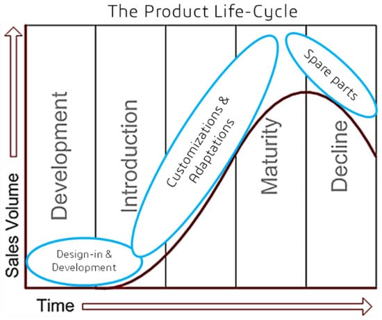
Figure 3.
Product lifecycle.
In order to evaluate the suitability of FIM for the different low-volume scenarios encountered throughout a typical product lifecycle, we chose one case for each stage of product lifecycle. Table 2 shows the case selection using different product lifecycle dimensions and focus area. This case selection will demonstrate applications of FIM in different industries with different functional requirements. In Section 5, each case will be discussed in detail.
Table 2.
Selected cases based on different product lifecycle dimensions.
4.2. Design Science
Design science has its roots in engineering [56] and it solves the problems by exploration through the new solution alternatives, explaining the explorative process followed by refinement and improvement of the process [56]. Contrary to the “traditional science”, design science produces system solutions that do not exist and seeks to change existing general patterns to achieve better results [57]. Design science has four main steps [58]: (1) Solution incubation; (2) Solution refinement; (3) Explanation through substantive theory; and (4) Explanation through formal theory. Solution incubation starts with problem diagnosis and understanding the problem causes and consequences and developing the first solution design, which is detailed enough to be implemented but may be incomplete. Solution refinement/evaluation includes design iteration and refinement of the initial solution design to verify the weakness and strength of the incubated solution including design improvements, implementation and evaluation. In the third phase, the researcher needs to proceed beyond problem solving by evaluating the developed artefact from a theoretical point of view and focuses on development of a substantive theory which is a context-dependent theory developed for a narrowly defined context and empirical application. The final phase involves development of a formal theory, if possible, which is aimed at broader generalizability of findings on new applications for the introduced solution(s) [58]. Figure 4 shows the concept of design science and four main steps.
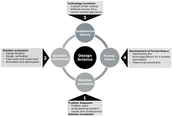
Figure 4.
Design science concepts and four main steps (The authors, based on [58,59]).
As FIM is a new technology and the parts chosen faced difficulties in production using IM or DAM, FIM processes need to be optimized to meet the functional requirements of each part, thereby requiring systematic experimentation. Design Science as a methodology allows us to systematically approach the problem and arrive at an outcome using an iterative approach and also to compare findings and generalize findings beyond the context of the specific cases.
5. Assessing the Suitability of FIM for Low Volume Production: A Design Science Approach
In Section 2 and Section 3, we discussed the limitations of IM, DAM and soft tooling in detail. In this section we will demonstrate how we follow the Design Science approach to systematically arrive at the solutions to produce the parts using FIM with the aim of exploring FIM suitability in different applications.
5.1. Problem Diagnosis and Solution Incubation by Initial Attempt to Produce FIM Parts
5.1.1. Case 1: Water Tap for a Plastic Water Bag—Product Development
A water tap for a plastic water bag (Figure 5) developed by a Danish company called SolarSack, is the first case analyzed in this research. Solarsack has designed a plastic water bag that can be filled with four liters of water and placed in the sun for four hours. UV radiation will break down live bacteria, and the water inside the bag will be cleaned from bacteria and the user can drink it. The bag is reusable for new water purification, but users initially found it to be difficult to use, as the purified water would have to be poured from the bag with no means of adjusting flow and avoiding spills.
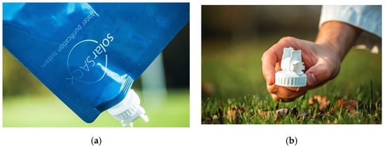
Figure 5.
(a) Plastic water bag developed by SolarSack; (b) The water tap made with FIM.
Accordingly, SolarSack decided to develop a water tap for the bag, which would enhance the user experience and minimize the risk of leakage and spills. Developing this water tap with conventional means would involve initially 3D-printing prototypes for user tests and design verification. However, none of the existing DAM techniques are capable of processing food grade materials, and none will allow designers to conduct tests for moldability and mechanical performance testing. PST was found to be unsuitable due to the significant complexity of the design, and the designers recognized that they would presumably need several iterations in order to arrive at an acceptable final result. For these reasons, the SolarSack team decided to use FIM for the development of the water tap. A total of six iterations were carried out before a suitable design had been found, which would have been prohibitively expensive with conventional metal tooling. Furthermore, the close resemblance of the FIM-made parts to conventionally injection-molded parts made it possible to start the creation of visuals used for the communication with potential users and customers. At present, the water tap has been migrated from FIM to a conventional metal tool, and more than 10.000 units have been produced and sold.
5.1.2. Case 2: Emergency Light Holder for a Life Jacket—Product Optimization
Making variants of an existing product is frequently costly and complicated. Situations of usage need to be carefully analyzed, and improvements need to be tested to determine whether they match—or outperform—the existing product. If the product is injection-molded, optimizations will often need to be injection-molded as well, and tooling investments may curtail improvement initiatives.
Since FIM allows for the manufacturing of injection-molded components without requiring tooling investments, the FIM process was chosen for the optimization of an emergency light holder used in the life jacket (Figure 6) produced by the Danish company Daniamant. Daniamant is one of the market players in the field of safety equipment manufacturing, for example, life jackets and lifebuoys for the maritime industry. The emergency light holder is a safety-critical item, which had been previously produced by injection molding in a high-performance polymer, and DAM was found to be unsuitable due to the lack of an equivalent material. On the other hand, due to the uncertain market demand for the improved version, it was difficult to justify the high cost of tooling design and manufacturing.
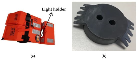
Figure 6.
(a) Life vest designed and manufactured by Daniamant; (b) Attachment interface of light holder manufactured by FIM.
Accordingly, FIM was chosen for the optimization, which brought the following benefits:
- It was possible to reduce the number of components from two to one by exploiting the design freedom of FIM. A one-part light holder eliminates the assembly process, which usually increases the risk of production failures and costs.
- It was possible to do focused tests on critical features. The attachment interface between the light holder and the life west is one such interface, and the design team decided to reduce print costs and material consumptions by creating printed tools that included only the interface portion. This allowed a targeted tensile strength test to be carried out, that demonstrated a considerable strength increase compared with the original design (600 N vs. 250 N).
At the end of the project, Daniamant decided to abort the attempt to launch an updated version. The decision to use FIM for development meant that the company saved substantial investments in metal mold tooling, and that the decision to abort could be made on an informed basis.
5.1.3. Case 3: Electrical Connector for Pressure Transmitter—Low-Volume Spare Parts Manufacturing
Neither DAM nor soft tooling can be used to process engineering materials such as POM, PPA or PPS. These materials may be processed by IM, but for short series production, there is a long lead-time and high cost of the tooling design and manufacturing. In addition to this, manufacturing of customized geometries using IM is not always possible due to design considerations. FIM may potentially address these limitations of IM when low volume production and design flexibility are needed. One of the cases that we evaluated was a pressure transmitter electrical connector to be manufactured by a high-performance engineering material (Figure 7). Pressure transmitters are used in many different applications such as refrigeration systems, air-conditioning, water pumps, air compressors, wind turbines etc.
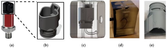
Figure 7.
(a) Pressure transmitter; (b) Deutsch electrical connector; (c) Printed closed cavity with an internal cavity including runner and venting channels; (d) Mold insert after injection molding; (e) Final part after dissolving in the solvent.
In this specific case, the connector is made in 18 different variants. Each variant is sold in between 200 and 2.000 pcs/year, which makes it a costly and complex component to manage. DAM was found to be unsuitable due to (a) the fact that the original component series had been made with injection molding and (b) the inability of DAM processes to handle the required materials.
With FIM, it was possible to reduce the time to produce the first component from 100 to 10 days, while at the same time reducing the costs of tooling from EUR 25.000 to EUR 2.500. The part had to be redesigned slightly to accommodate FIM design guidelines (predominantly the need for wall thicknesses that do not vary by more than 50%), and several variants were tried out (including one that carried an over molded rubber collar for improved water tightness).
This case, which demonstrates the ability of FIM to manufacture complex components in complex materials, has inspired AddiFab to further pursue opportunities for spare parts manufacturing.
5.2. Solution Refinement by Optimizing the FIM Process for the Parts
In the previous sub-section, we showed several cases where IM, PST and DAM were inappropriate due to economic constraints, design limitations and/or limited choice of materials. In each of the three cases, FIM was implemented as a means to bypass these limitations, and each case delivered a satisfactory outcome. Each case also contributed significantly to the generation of knowledge of implementations of FIM in different product lifecycle management situations. Accordingly, key learnings and improvement opportunities are listed in Table 3.
Table 3.
Key learning and improvement opportunities for selected cases.
5.3. Cross-case Analysis using Context, Intervention, Mechanism and Outcomes
In this section, based on the empirical cases discussed in Sub-Section 5.1, followed by solution refinement in Sub-Section 5.2, we try to conduct a “cross-case” analysis using the context, intervention and mechanisms to define a substantive theory for suitability of FIM for short series production.
In the first case FIM was used to manufacture the representative prototypes with desired mechanical strength and over-molded features to address the mechanical functionality and water tightness, respectively. Several design iterations were carried out to successfully process the food grade polymer material.
In the second case, the design was optimized with a focus on the critical features and combining multiple parts into one single part to reduce the assembly failure and costs. Then, FIM was used to manufacture the optimized geometry in high performance polymer.
In the third case, FIM enabled the manufacturer to redesign the original geometry to make it suitable for FIM and manufacture it with PPS, which was a high-performance engineering material as an alternative to PBT. As shown, in all cases, FIM enabled the manufacturers to benefit from design freedom of AM and material diversity of IM where the high cost of traditional tooling design and manufacturing was very difficult to be justified for short series production. This cross-case analysis leads us to infer that FIM will be a suitable manufacturing technology when design freedom/iteration and using the right material considering the economic aspects are essential. The comparison of the cases in terms of context, intervention, mechanism and outcome are shown below in Table 4.
Table 4.
Comparison of the cases in terms of context, intervention, mechanism and outcome.
5.4. Generalizability of Findings on Application of FIM for Low-volume Production
As demonstrated through the three cases, FIM is suitable for low-volume manufacturing when design freedom, multiple iterations and access to specific materials that cannot be additively manufactured are required. Design freedom enables the designer to match—or improve upon—the design of an existing product (cases two and three) or explore alternative designs during the product development phase (case one) without any compromise on part characteristics. The needs to (a) Explore alternative designs, (b) Match or improve on existing designs and (c) Produce parts in low volumes with materials that can only be injection-molded may be generalized to a wide range of cases from the injection molding industry. It should be also mentioned that as FIM can process almost all traditional injection moldable materials, a manufacturer has a wide selection of alternative materials that may replace original materials to fulfill specific performance requirements. This is especially important for spare parts manufacturing (case three). From a supply chain point of view, as can be seen in Table 1, FIM enables the manufacturers to define supply chain objectives independent from the part complexity and material type. Thus, FIM can be used as a unified source for multiple short-series production applications across product development, product improvement and for producing spare parts. The cases also demonstrate that using FIM to produce a part for the first time while meeting all the requirements will need careful analysis and process optimization.
Although the selected cases in this study are within the food, personal protective equipment and refrigeration industries, the suitability of FIM can be potentially generalized to other industries such as medical devices, dental and other industries where there is a need for customized low-volume production and where the unavailability of suitable materials implies that DAM cannot be used. It should be also mentioned that manufacturers can continue with mass production by switching from FIM to conventional metal tooling once high-volume production is required. Currently, there are some limitations for demolding polycarbonate-based materials such as PBT, as they are not fully compatible with alkaline solvents.
6. Discussion
In this research study, we investigated the suitability of FIM for low volume injection molded parts by using a design science approach. In order to explore the suitability of FIM for low volume production, the benefits and drawbacks of IM, DAM and PST were reviewed (Table 1). As it can be seen in Table 1, IM benefits from material diversity and scalability, but significantly suffers from limited design freedom, long lead-time and high costs of mold tooling for low volume production. DAM can address some of these drawbacks by offering short lead times, low start-up costs and design freedom. However, DAM remains unsuitable for low volume production due to restricted choice of materials [37], anisotropic mechanical properties [32,33], poor dimensional accuracy [35], slow process speed and limited scalability [34]. In line with the existing literature, the cases explored as part of the research also highlighted the limitation of DAM making it unsuitable for those applications. PST can combine some of the advantages of IM and DAM, but still suffers from design complexity and the inability to process high performance engineering materials, with or without reinforcement materials such as glass or carbon fiber/beads. Lack of a suitable manufacturing technology for low volume production leads us towards exploring FIM as a potential solution to address the existing challenges for low volume injection molded parts.
We used a design science approach (Figure 4) to assess the suitability of FIM for low volume production. Design science allows us to diagnose the problem, incubate initial solutions to produce FIM parts and follow a systematic iterative approach to refine the initial solution. In order to demonstrate the wide scope of application of FIM with broad functional requirements, we chose one case for each stage of the product lifecycle (Figure 3) including new product development, optimization of existing part and spare part manufacturing (Table 2). The cases demonstrate that there are different challenges in the first design iteration for parts to be manufactured by FIM in all cases. Thus, it may not be possible to produce parts with existing designs directly using FIM unless some suitable design changes are made, and the processes are optimized. This is consistent with the findings from design for AM literature that a part designed for conventional manufacturing may not be optimal for producing using DAM [30,60,61,62,63].
In the cases studied for this research, the challenges were mainly addressed through new design or re-design of the existing components. In the last case, the solution was refined through a combination of redesigning and replacing PBT with PPS as an alternative material with even better mechanical functionality. Thus, the biggest advantages of FIM lie in enabling the users to re-design the parts (even after freezing phase) with minimum additional costs and replace the original material with other high-performance materials (freedom in material selection).
To generalize the findings beyond the cases, we conducted a “cross-case” analysis and found that the common mechanism in all cases were the flexibility in design or redesign due to combination of low start-up costs, short lead times and design freedom of DAM, with the scalability and material versatility of IM that enabled FIM to successfully manufacture the parts. This led us to infer that the FIM process is suitable for product development, as well as for cases where component (re)design or replacement of an original material with an alternative material is needed, thereby significantly increasing the domain of application. As the cases were selected from different industries with completely different applications from different stages of product lifecycle, our findings can be potentially generalized on new applications for a broad cross-section of industries with successful outcomes.
7. Conclusions and Opportunities for Future Research
FIM combines the low start-up costs, short lead-times and design freedom of DAM with the versatility and scalability of IM to allow manufacturers to bring products to the market, and to cost-efficiently sustain their product lifecycles where low-volume manufacturing is required. It also enables the manufacturers to customize the design at different stages of the product lifecycle without additional costs. Although in this study we demonstrated the suitability of FIM for low volume production using a design science approach, FIM needs to be further evaluated on a broader range of applications from different industries. This will help in generalizing the applicability as well identifying the limits of using FIM. Therefore, for future work, the authors encourage the researchers to apply FIM to new applications in order to generate new knowledge about opportunities and the limitations of FIM.
Although FIM is a promising manufacturing technology, there is some room for further developments: (1) The solvent material used in the demolding process is incompatible with some polymers such as PBT. (2) The demolding process is time consuming and decreases the agility of the FIM process. (3) The thermal conductivity of printed molds is different from conventional metal molds, and this may require process adaptations for processing crystalline and semi-crystalline materials. (4) Air entrapments will result in short or incompletely filled mold cavities. Although this issue can be addressed by drilling or minor mold design adjustments, but filling simulations are suggested as an area for future work. (5) FIM has higher unit costs than other DAM technologies and these costs will increase by increasing the size of the parts to be manufactured by FIM. There is also a need to develop a scientific approach to choose the appropriate parts, which can be produced using FIM. In addition, there is a need to develop detailed lifecycle costing-based analysis of FIM produced parts and to develop business cases for the same.
The contribution of the study lies in demonstrating the suitability of FIM for low volume injection molded parts using a design science approach. While Tosello et al. [9] performed a cost optimization for integrating AM in the IM process chain, our study is the first to systematically evaluate the suitability of FIM. The successful outcomes of the selected cases are a strong indication of the suitability of the technology and should encourage further adoption for cases where it is most appropriate.
Author Contributions
Conceptualization, E.S., A.C., L.G.S. and B.V.W.; methodology, E.S., A.C. and L.G.S.; software, E.S. and A.C.; validation, E.S., A.C., B.V.W. and L.G.S.; formal analysis, E.S. and A.C.; investigation, E.S., A.C., L.G.S. and B.V.W.; resources, L.G.S. and A.C.; data curation, E.S. and A.C.; writing—original draft preparation, E.S.; writing—review and editing, E.S., A.C., B.V.W., L.G.S. and S.D.F.; visualization, E.S.; supervision, A.C., B.V.W. and L.G.S.; project administration, L.G.S., A.C., B.V.W. and S.D.F.; funding acquisition, L.G.S. and A.C. All authors have read and agreed to the published version of the manuscript.
Funding
This research was funded by Innovationsfonden, grant number 8053-00116B.
Institutional Review Board Statement
Not applicable.
Informed Consent Statement
Not applicable.
Data Availability Statement
No new data were created or analyzed in this study. Data sharing is not applicable to this article.
Conflicts of Interest
The authors declare no conflict of interest.
References
- Holmström, J.; Partanen, J. Digital manufacturing-driven transformations of service supply chains for complex products. Supply Chain Manag. 2014, 19, 421–430. [Google Scholar] [CrossRef]
- Khajavi, S.H.; Partanen, J.; Holmström, J. Additive manufacturing in the spare parts supply chain. Comput. Ind. 2014, 65, 50–63. [Google Scholar] [CrossRef]
- Kumbhar, N.N.; Mulay, A.V. Post processing methods used to improve surface finish of products which are manufactured by additive manufacturing technologies: A review. J. Inst. Eng. (India) Ser. C 2018, 99, 481–487. [Google Scholar] [CrossRef]
- Baumers, M.; Dickens, P.; Tuck, C.; Hague, R. The cost of additive manufacturing: Machine productivity, economies of scale and technology-push. Technol. Forecast. Soc. Chang. 2016, 102, 193–201. [Google Scholar] [CrossRef]
- Berman, B. 3-D printing: The new industrial revolution. Bus. Horiz. 2012, 55, 155–162. [Google Scholar] [CrossRef]
- Mellor, S.; Hao, L.; Zhang, D. Additive manufacturing: A framework for implementation. Int. J. Prod. Econ. 2014, 149, 194–201. [Google Scholar] [CrossRef]
- Oettmeier, K.; Hofmann, E. Impact of additive manufacturing technology adoption on supply chain management processes and components. J. Manuf. Technol. Manag. 2016, 27, 944–968. [Google Scholar] [CrossRef]
- Dimla, D.E.; Camilotto, M.; Miani, F. Design and optimisation of conformal cooling channels in injection moulding tools. J. Mater. Process. Technol. 2005, 164, 1294–1300. [Google Scholar] [CrossRef]
- Tosello, G.; Charalambis, A.; Kerbache, L.; Mischkot, M.; Pedersen, D.B.; Calaon, M.; Hansen, H.N. Value chain and production cost optimization by integrating additive manufacturing in injection molding process chain. Int. J. Adv. Manuf. Technol. 2019, 100, 783–795. [Google Scholar] [CrossRef]
- Achillas, C.; Tzetzis, D.; Raimondo, M.O. Alternative production strategies based on the comparison of additive and traditional manufacturing technologies. Int. J. Prod. 2017, 55, 3497–3509. [Google Scholar] [CrossRef]
- Niaki, M.K.; Nonino, F. Impact of additive manufacturing on business competitiveness: A multiple case study. J. Manuf. Technol. Manag. 2017, 28, 56–74. [Google Scholar] [CrossRef]
- Petrovic, V.; Vicente Haro Gonzalez, J.; Jordá Ferrando, O.; Delgado Gordillo, J.; Ramón Blasco Puchades, J.; Portolés Griñan, L. Additive layered manufacturing: Sectors of industrial application shown through case studies. Int. J. Prod. Res. 2011, 49, 1061–1079. [Google Scholar] [CrossRef]
- Sharifi, E.; Chaudhuri, A.; Wæhrens, B.V.; Staal, L.G.; Davoudabadi Farahani, S. Part Selection for Freeform Injection Molding: Framework for Development of a Unique Methodology. In Proceedings of the IFIP International Conference on Advances in Production Management Systems, Novi Sad, Serbia, 30 August–3 September 2020; pp. 723–730. [Google Scholar]
- Goodship, V. Practical Guide to Injection Moulding, 2nd ed.; Smithers Rapra: Shropshire, UK, 2017. [Google Scholar]
- Ainsley, C.; Gong, H.Q. Costs and performance of injection moulding tools produced using slip casting. Rapid Prototyp. J. 1999, 5, 35–44. [Google Scholar] [CrossRef]
- Khosravani, M.R.; Nasiri, S. Injection molding manufacturing process: Review of case-based reasoning applications. J. Intell. Manuf. 2020, 31, 847–864. [Google Scholar] [CrossRef]
- Jiang, J. A novel fabrication strategy for additive manufacturing processes. J. Clean Prod. 2020, 272, 122916. [Google Scholar] [CrossRef]
- Gupta, N.; Weber, C.; Newsome, S. Additive Manufacturing: Status and Opportunities; Science and Technology Policy Institute: Washington, DC, USA, 2012. [Google Scholar]
- Kadkhoda-Ahmadi, S.; Hassan, A.; Asadollahi-Yazdi, E. Process and resource selection methodology in design for additive manufacturing. Int. J. Adv. Manuf. Technol. 2019, 104, 2013–2029. [Google Scholar] [CrossRef]
- Bikas, H.; Lianos, A.K.; Stavropoulos, P. A design framework for additive manufacturing. Int. J. Adv. Manuf. Technol. 2019, 103, 3769–3783. [Google Scholar] [CrossRef]
- Pan, Y.; Zhou, C.; Chen, Y.; Partanen, J. Multitool and multi-axis computer numerically controlled accumulation for fabricating conformal features on curved surfaces. J. Manuf. Sci. Eng. ASME 2014, 136, 031007. [Google Scholar] [CrossRef]
- Rivera, F.J.M.; Arciniegas, A.J.R. Additive manufacturing methods: Techniques, materials, and closed-loop control applications. Int. J. Adv. Manuf. Technol. 2020, 109, 17–31. [Google Scholar] [CrossRef]
- ASTM ISO/ASTM52900-15. In Standard Terminology for Additive Manufacturing—General Principles—Terminology; ASTM International: West Conshohocken, PA, USA, 2015.
- Tofail, S.A.M.; Koumoulos, E.P.; Bandyopadhyay, A.; Bose, S.; O’Donoghue, L.; Charitidis, C. Additive manufacturing: Scientific and technological challenges, market uptake and opportunities. Mater. Today. 2018, 21, 22–37. [Google Scholar] [CrossRef]
- Ford, S.; Despeisse, M. Additive manufacturing and sustainability: An exploratory study of the advantages and challenges. J. Clean Prod. 2016, 137, 1573–1587. [Google Scholar] [CrossRef]
- Ribeiro, I.; Matos, F.; Jacinto, C.; Salman, H.; Cardeal, G.; Carvalho, H.; Godina, R.; Peças, P. Framework for Life Cycle Sustainability Assessment of Additive Manufacturing. Sustainability 2020, 12, 929. [Google Scholar] [CrossRef]
- Renjith, S.C.; Park, K.; Kremer, G.E.O. A Design Framework for Additive Manufacturing: Integration of Additive Manufacturing Capabilities in the Early Design Process. Int. J. Precis. 2020, 21, 329–345. [Google Scholar] [CrossRef]
- Mashhadi, A.R.; Esmaeilian, B.; Behdad, S. Impact of additive manufacturing adoption on future of supply chains. In Proceedings of the International Manufacturing Science and Engineering Conference, Charlotte, NC, USA, 8–12 June 2015; p. V001T02A064. [Google Scholar]
- Gao, W.; Zhang, Y.; Ramanujan, D.; Ramani, K.; Chen, Y.; Williams, C.B.; Wang, C.C.; Shin, Y.C.; Zhang, S.; Zavattieri, P.D. The status, challenges, and future of additive manufacturing in engineering. Comput. Aided Des. 2015, 69, 65–89. [Google Scholar] [CrossRef]
- Hällgren, S.; Pejryd, L.; Ekengren, J. (Re)Design for Additive Manufacturing. Procedia CIRP 2016, 50, 246–251. [Google Scholar] [CrossRef]
- Abdulhameed, O.; Al-Ahmari, A.; Ameen, W.; Mian, S.H. Additive manufacturing: Challenges, trends, and applications. Adv. Mech. Eng. 2019, 11, 1687814018822880. [Google Scholar] [CrossRef]
- Ziemian, C.; Sharma, M.; Ziemian, S. Anisotropic mechanical properties of ABS parts fabricated by fused deposition modelling. Mech. Eng. 2012, 23, 159–180. [Google Scholar]
- Kok, Y.; Tan, X.P.; Wang, P.; Nai, M.L.S.; Loh, N.H.; Liu, E.; Tor, S.B. Anisotropy and heterogeneity of microstructure and mechanical properties in metal additive manufacturing: A critical review. Mater. Des. 2018, 139, 565–586. [Google Scholar] [CrossRef]
- Gokuldoss, P.K.; Kolla, S.; Eckert, J. Additive manufacturing processes: Selective laser melting, electron beam melting and binder jetting—Selection guidelines. Materials 2017, 10, 672. [Google Scholar] [CrossRef]
- Islam, M.N.; Boswell, B.; Pramanik, A. An investigation of dimensional accuracy of parts produced by three-dimensional printing. In Proceedings of the World Congress on Engineering, London, UK, 3–5 July 2013; pp. 522–525. [Google Scholar]
- Dowling, L.; Kennedy, J.; O’Shaughnessy, S.; Trimble, D. A review of critical repeatability and reproducibility issues in powder bed fusion. Mater. Des. 2020, 186, 108346. [Google Scholar] [CrossRef]
- Ngo, T.D.; Kashani, A.; Imbalzano, G.; Nguyen, K.T.; Hui, D. Additive manufacturing (3D printing): A review of materials, methods, applications and challenges. Compos. B. Eng. 2018, 143, 172–196. [Google Scholar] [CrossRef]
- Thomas, D.S.; Gilbert, S.W. Costs and cost effectiveness of additive manufacturing. NIST Spec. Publ. 2014, 1176, 12. [Google Scholar]
- Khosravani, M.R.; Nasiri, S.; Weinberg, K. Application of case-based reasoning in a fault detection system on production of drippers. Appl. Soft. Comput. 2014, 75, 227–232. [Google Scholar] [CrossRef]
- Meisel, N.A.; Williams, C.B.; Druschitz, A. Lightweight metal cellular structures via indirect 3D printing and casting. In Proceedings of the 23rd Annual International Solid Freeform Fabrication Symposium—An Additive Manufacturing Conference, SFF, Austin, TX, USA, 6–8 August 2012; pp. 162–176. [Google Scholar]
- Rosato, D.V.; Rosato, M.G. Injection Molding Handbook; Springer Science & Business Media: Heidelberg, Germany, 2012. [Google Scholar]
- Mischkot, M.; Davoudinejad, A.; Charalambis, A.; Hofstätter, T.; Tosello, G.; Pedersen, D.B.; Hansen, H.N. Dimensional accuracy of Acrylonitrile Butadiene Styrene injection molded parts produced in a pilot production with an additively manufactured insert. In Proceedings of the 33rd Annual Meeting of the Polymer Processing Society, Cancun, Mexico, 10–14 December 2017. [Google Scholar]
- Equbal, A.; Sood, A.K.; Shamim, M. Rapid tooling: A major shift in tooling practice. Manuf. Ind. Eng. 2015, 14, 3–4. [Google Scholar] [CrossRef]
- Rosochowski, A.; Matuszak, A. Rapid tooling: The state of the art. J. Mater. Process. Technol. 2000, 106, 191–198. [Google Scholar] [CrossRef]
- Mischkot, M.; Krexner, G.; Soprunyuk, V.; Schranz, W.; Pedersen, D.B.; Tosello, G.; Hansen, H.N. Influence of thermal ageing on the mechanical properties of an additively manufactured photopolymer used in soft tooling applications. In Proceedings of the 18th International Conference of the European Society for Precision Engineering and Nanotechnology, Venice, Italy, 4–8 June 2018; pp. 241–242. [Google Scholar]
- Yang, Z.; Peng, H.; Wang, W.; Liu, T. Effective properties of particle reinforced polymeric mould material towards reducing cooling time in soft tooling process. J. Appl. Polym. Sci. 2010, 116, 2658–2667. [Google Scholar]
- Bourell, D.; Kruth, J.P.; Leu, M.; Levy, G.; Rosen, D.; Beese, A.M.; Clare, A. Materials for additive manufacturing. CIRP Ann. Manuf. Technol. 2017, 66, 659–681. [Google Scholar] [CrossRef]
- Ivanova, O.; Williams, C.; Campbell, T. Additive manufacturing (AM) and nanotechnology: Promises and challenges. Rapid Prototyp. J. 2013, 19, 353–364. [Google Scholar] [CrossRef]
- Franchetti, M.; Kress, C. An economic analysis comparing the cost feasibility of replacing injection molding processes with emerging additive manufacturing techniques. Int. J. Adv. Manuf. Technol. 2017, 88, 2573–2579. [Google Scholar] [CrossRef]
- Brajlih, T.; Valentan, B.; Balic, J.; Drstvensek, I. Speed and accuracy evaluation of additive manufacturing machines. Rapid Prototyp. J. 2011, 17, 64–75. [Google Scholar] [CrossRef]
- Hassen, A.A.; Kirka, M.M. Additive Manufacturing: The Rise of a Technology and the Need for Quality Control and Inspection Techniques. Mat. Eval. 2018, 76, 438–453. [Google Scholar]
- Gibson, I.; Rosen, D.; Stucker, B. Additive Manufacturing Technologies: 3D Printing, Rapid Prototyping, and Direct Digital Manufacturing, 2nd ed.; Springer Science & Business Media: Heidelberg, Germany, 2015. [Google Scholar]
- Liu, W.; Li, L.; Kochhar, A.K. A method for assessing geometrical errors in layered manufacturing. Part 1: Error interaction and transfer mechanisms. Int. J. Adv. Manuf. Tech. 1998, 14, 637–643. [Google Scholar] [CrossRef]
- Kim, H.; Lin, Y.; Tseng, T.L.B. A review on quality control in additive manufacturing. Rapid Prototyp. J. 2018, 24, 645–669. [Google Scholar] [CrossRef]
- Castellion, G.; Markham, S.K. Perspective: New Product Failure Rates: Influence of Argumentum ad Populum and Self-Interest. J. Prod. Innov. 2013, 30, 976–979. [Google Scholar] [CrossRef]
- Simon, H.A. The Sciences of the Artificial, 3rd ed.; MIT Press: Cambridge, MA, USA, 2019. [Google Scholar]
- Romme, A.G.L. Making a Difference: Organization as Design. Organ. Sci. 2003, 14, 558–573. [Google Scholar] [CrossRef]
- Holmström, J.; Ketokivi, M.; Hameri, A.P. Bridging practice and theory: A design science approach. Decis. Sci. 2009, 40, 65–87. [Google Scholar] [CrossRef]
- Venable, J.R. The Role of Theory and Theorising in Design Science Research. In Proceedings of the 1st International Conference on Design Science in Information Systems and Technology, Claremont, CA, USA, 24 February 2006; pp. 1–18. [Google Scholar]
- Atzeni, E.; Salmi, A. Economics of additive manufacturing for end-usable metal parts. Int. J. Adv. Manuf. Technol. 2012, 62, 1147–1155. [Google Scholar] [CrossRef]
- Yang, S.; Tang, Y.; Zhao, Y.F. A new part consolidation method to embrace the design freedom of additive manufacturing. J. Manuf. Process. 2015, 20, 444–449. [Google Scholar] [CrossRef]
- Yang, S.; Zhao, Y.F. Additive manufacturing-enabled design theory and methodology: A critical review. Int. J. Adv. Manuf. Technol. 2015, 80, 327–342. [Google Scholar] [CrossRef]
- Alfaify, A.; Saleh, M.; Abdullah, F.M.; Al-Ahmari, A.M. Design for Additive Manufacturing: A Systematic Review. Sustainability 2020, 12, 7936. [Google Scholar] [CrossRef]


Publisher’s Note: MDPI stays neutral with regard to jurisdictional claims in published maps and institutional affiliations. |
© 2021 by the authors. Licensee MDPI, Basel, Switzerland. This article is an open access article distributed under the terms and conditions of the Creative Commons Attribution (CC BY) license (http://creativecommons.org/licenses/by/4.0/).