Abstract
For quadrotor control applications, it is necessary to rely on attitude angle changes to indirectly achieve the position trajectory tracking purpose. Several existing literature studies omit the non-negligible attitude transients in the position controller design for this kind of cascade system. The result leads to the position tracking performance not being as good as expected. In fact, the transient behavior of the attitude tracking response cannot be ignored. Therefore, the closed-loop stability of the attitude loop as well as the position tracking should be considered simultaneously. In this study, the flight controller design of the position and attitude control loops is presented based on an integral backstepping control algorithm. This control algorithm relies on the derivatives of the associated virtual control laws for implementation. Examining existing literature, the derivatives of the virtual control law are realized approximated by numerical differentiations. Nevertheless, in practical scenarios, the numerical differentiations will cause the chattering phenomenon of control signals in the presence of unavoidable measurement noise. The noise-induced control signals may further cause damage to the actuators or even diverge the system response. To address this issue, the analytic form for the derivative of the virtual control law is derived. The time derivative virtual control law is analyzed and split into the disturbance-independent compensable and disturbance-dependent non-compensable terms. By utilizing the compensable term, the control chattering due to the differentiation of the noise can be avoided significantly. The simulation results reveal that the proposed control algorithm has a better position tracking performance than the traditional dual-loop control scheme. Meanwhile, a relatively smooth control signal can be obtained for a realistic control algorithm realization. Simulations are provided to illustrate the position tracking issue of a quadrotor and to demonstrate the effectiveness of the proposed compromised control scheme.
1. Introduction
The quadrotor has been widely used in economic, commercial, entertainment [1], and military industries—for example, prospecting, documentary filming, spraying medicine, reconnaissance, attack, and other tasks. As a result, quadrotors play an essential role in the livelihoods, businesses, and the military for people. Position trajectory control is the key to realizing these applications when flying in turbulent environments [2,3], flight path planning [4], and avoiding dynamic obstacles [5].
Due to the maneuverability and applicability of the quadrotors, it has attracted extensive research interest in recent years. The study [6] presented an adaptive controller that introduced the artificial neural network to adjust the control gain adaptively. The study [7] proposed a combination of backstepping and sliding model approaches based on a PID-type sliding surface to address the position control problem of the quadrotors. In [8], an optimal bounded robust control algorithm for secure autonomous navigation of a quadrotor is proposed. Other related research includes: the backstepping controllers [9,10,11,12,13,14], sliding mode controllers [15,16], and adaptive controllers [6,17,18]. Several research studies considered fuselage drag in the model [16,18]. The viscous drag force depends on the fluid viscosity, air speed, humidity, and the fuselage design prototype. It is hard to make a deterministic analysis of the effects of drag. In general, the quantitative results are estimated by conducting the experimental studies [19,20]. Nevertheless, some researchers did not consider the drag force in the external disturbances [8,9,11,15]. To fulfill the practical scenarios, the time-varying, and state-dependent external disturbances are considered in these studies [21,22,23]. Some of the studies do not include measurement noise [6,7,8,10,15,18,24] and actuator saturation limitations [25] in the numerical simulations. These imperfections lead to mismatches between numerical simulation and practical implementations. In fact, the saturation of actuators may lead to system instability. The measurement noise may be amplified when conducting the numerical differentiation. This skill causes serious control chattering of the control signals. With regard to the position flight controller, some of the articles [7,9,10,11,13,18,26,27] separate the dynamics into the position loop and attitude loop, and then design the controller individually. In these works, the attitude transients are ignored based on the assumption that the attitude response is fast enough. However, transient behavior in the attitude loop does exist due to the nature of the quadrotor flight properties and finite inner-loop control bandwidth. Therefore, the tracking performance of the position loop is limited due to the transient response of the attitude loop. To address this cascade transition issue, the integral backstepping control algorithm is introduced inspired by the work [28], where the integral term is applied to suppress the effects of disturbances [29]. However, the construction of the virtual control law needs information from unmeasurable states. The studies [9,14] conducted the numerical differentiation and applied a low-pass filter. It should be mentioned that the drawback of a low-pass filter gives rise to the phase delay. To avoid the control delay problem, the analytic form of virtual controls is derived. The analytic form is obtained by dividing the virtual control into a disturbance-independent term and a disturbance-dependent term and then applying the compensation for the former. Simulation results reveal that the relatively smooth control signals are available from the proposed analytic form of virtual controls.
The objective of this study aims to develop a position tracking control algorithm for a quadrotor in the presence of both the disturbance and the measurement noise. Instead of presenting a new robust control theory, the topic of this paper is to solve a controller design issue when applying the backstepping scheme. In the existing backstepping control algorithms, the virtual control inputs contain unmeasurable information. This issue can be dealt with in two ways: taking the time derivative on the state variable directly or designing an extra observer. On the one hand, taking the time derivative will induce serious control chattering when the state variables contain measurement noise. On the other hand, designing an extra state estimator or an observer would definitely increase realization complexities. Therefore, in the paper, an analytic way is presented. The proposed analytic flight control algorithm, which uses available state information only, can be taken as a compromised control law for practical consideration. Therefore, applying the virtual input derivative as well as designing the observer design can be avoided. Most importantly, the serious control chattering induced by measurement noise can be attenuated and thus the control saturation can be avoided as well. This advantage makes a great contribution to the position control closed-loop stability.
The contributions of this study are summarized as follows: (i) proposing the integral backstepping control algorithm for the quadrotor position tracking demands; (ii) providing the corresponding stability analysis based on Lyapunov theory in the presence of the unknown disturbances; (iii) deriving the analytic form of the virtual controls so that more smooth control signals can be obtained by the proposed analytic solution instead of using the numerical differentiation directly; and (iv) highlighting the advantage of the proposed flight controller with consideration of disturbances and measurement noise for comparative studies. Simulation results reveal that the proposed integral backstepping control algorithm with the analytic virtual control law has a better trajectory tracking performance. Meanwhile, smoother realizable control signals are obtained.
The organization of this study is concluded as follows: the dynamics modeling and the actuator analysis are performed in Section 2; the proposed integral backstepping control algorithm is derived in Section 3, the correlated stability analysis is provided; the comparison of the numerical simulations is presented in Section 4; finally, the conclusions are made in Section 5.
2. Dynamics Modeling
In this paper, to address the design issue clearly, we focus on 3-DoF quadrotor dynamics. Hence, the simplified 3-DoF dynamics model is adopted rather than the 6-DoF quadrotor systems. It is worth noticing that the considered 3-DoF model is a classical example to illustrate the control difficulty for such cascade nonlinear systems subject to both the matched and mismatched disturbances. To address this control problem, the 3-DoF dynamic model of a quadrotor is considered in this study to provide a deeper understanding of the proposed algorithm. The dynamic configuration for a 3-DoF quadrotor system is shown in Figure 1. The geometry parameters are summarized in Table 1.
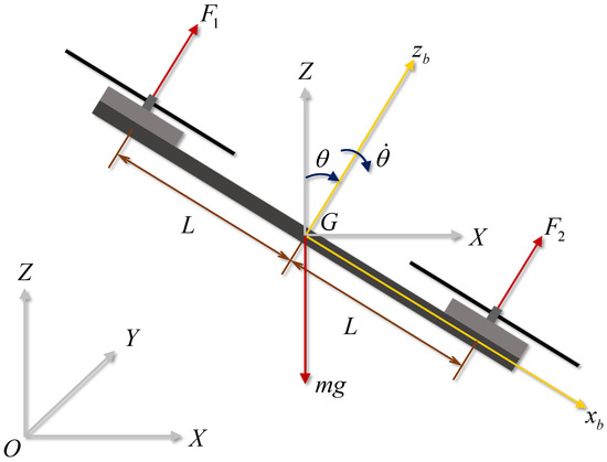
Figure 1.
The dynamic configuration of the 3-DoF quadrotor system.

Table 1.
Explanation of the physical quantities of the quadrotor planar motion system.
The quadrotor system contains two brushless direct currents (BLDC) motors to provide the thrusts to drive the quadrotor system. In practical scenarios, each BLDC motor is controlled by the electric speed controller (ESC). The ESC controls the rotation speed of the BLDC motor to the desired speed according to given pulse width modulation (PWM) duty cycles. In other words, there exists a simple mapping relationship between desirable rotor speeds and the given PWM duty cycles. Refer to [15,30,31], and the thrust generated by i-th rotor with the speed , , is modeled as
where is the thrust coefficient. On the basis of (1), the total force F and torque M can be expressed as
where the force distribution matrix is defined as
The system kinetic energy includes the translation kinematic energy and the rotational kinematic energy ; the potential energy with respect to the datum is . Thus, the Lagrangian can be represented by
The Lagrange equation is
where the generalized coordinate represents x, z, and ; the generalized force is , , and , respectively. The notations and represent and . The following time-varying and state-dependent disturbance models of the external disturbances , , and are considered:
where , , and are unknown time-varying disturbances used to simulate the influence from the wind gusts; , , and are correlated to the state-dependent aerodynamic drag forces. , , and are the associated viscous drag coefficients.
Hence, on the basis of the dynamics (9)–(11), given the desired trajectories in x- and z-directions, the control laws F and M are designed. Then, based on the actuator model (4), the desired rotation speeds of BLDC are obtained to achieve the trajectory tracking demands.
It should be noticed that the BLDC motors have a command deadzone in the low-speed region. This imperfection induces the undesired response and instability of the system. To address this issue, the minimum motor speed command, , is considered in this study. Furthermore, to provide enough margin of control torque in the landing phase, the minimum force and the maximum are imposed. The quantities of , , and are set by
where is the idle speed value that is dependent on the hardware configuration. From (4) and (12), the maximum value of the magnitude of control torque can be given by
where F is the desired control force to manipulate the z-directional flight dynamics and will be designed later. and are the maximum torques at the upper and lower limits of the BLDC motor speed, respectively. Note that usually is more important to consider than . This is because the motor speed cannot be negative. Generally, and satisfy
Conclusively, the following saturation conditions are considered in the flight controller implementation:
for .
3. Flight Controller Design
The 3-DoF quadrotor model has been derived in (9)–(11). The system contains two independent control inputs: one is the translational force F and the other is the rotational torque M. The main design task is to develop proper control laws to achieve the desired flight demands. In this study, the control objective is the trajectory tracking control, namely , and keeps the attitude stable simultaneously. In a physical sense, the force F can be independently designed to achieve altitude tracking control. However, the translation x relies on the change of the attitude making the system have the force component in the x-direction. Therefore, the system dynamics (9)–(11) are divided into a fully-actuated subsystem and an under-actuated subsystem described as follows:
The control force F is designed for the subsystem (19) to achieve the desired altitude . Based on the designed control force F, the control torque M is then designed for the subsystem (20) to achieve the desired position . Meanwhile, the attitude remains stable. For the convenience of the flight controller design, the stability analysis of the general error dynamics in the presence of unknown perturbations is presented firstly. The altitude and attitude controllers are then designed.
3.1. Stability Analysis of General Error Dynamics
Consider a class of the error system as follows:
where is the error state vector, is a Hurwitz system matrix, and is an unknown perturbation. Assume that the perturbation satisfies
where is the Euclidean 2-norm, and is a known upper bound of the perturbation.
To perform the stability analysis, consider the Lyapunov function candidate of the quadratic form:
where . Taking the time derivative of (23) along the system trajectory (21), it follows that
From the Cauchy–Schwarz inequality, the term satisfies
Applying the matrix norm property, the symmetric matrix can be related to its maximum eigenvalue ; that is,
Rayleigh’s inequality gives . According to Rayleigh’s inequality, (22), and (29), (26) follows with:
where
Equation (30) indicates that the stability is guaranteed when . However, there is no conclusion when . Hence, it can be deduced that the error state vector will approach a region , i.e.,
where
The stability result for the general error system (21) is summarized as follows:
3.2. Altitude Proportional-Integral-Derivative Controller Design
Consider the fully-actuated subsystem shown in (19). Assume that the change rate of disturbance is bounded by
where is a known value. Define the tracking errors and as
The error dynamics is then obtained:
Design the proportional-integral-derivative (PID) control law as
where
and the control gain pair . Substituting the control law (37) into (36) gives the closed-loop system as
To analyze the stability, define an extended state as follows:
Then, the extended closed-loop system (39) can be described by
where is the augmented error state vector, is the extended disturbance vector, and the closed-loop system matrix is
respectively.
Obviously, (41) is the standard form of the general error system described in (21). Therefore, by Theorem 1, the design problem is to choose the control gain pair properly such that the matrix is Hurwitz. As a consequence, there exists a Lyapunov function , where and thereby is achieved, where is the feasible solution of (25):
Moreover, according to (31).
As a result, the tracking error will approach a region eventually, i.e.,
Remark 1.
Note that providing the external disturbance satisfies the slow time-varying condition, i.e., , and it can be deduced from (44) that and , which further implies that the fully-actuated subsystem is asymptotically stable.
3.3. Position Integral Backstepping Controller Design
Consider the under-actuated subsystem described in (20). Assume that the disturbances and satisfy
where , , and are known constants. Since the control force F has already been designed for the subsystem (19) to achieve the desired altitude , the control torque M should be further designed for the subsystem (20) to achieve the desired position and to keep the attitude stable. What follows is the illustration of the integral backstepping controller (IBC) design procedure used to highlight the tracking control problem for such cascade system (20).
Following the similar manners presented in the previous section, define the position tracking errors and as follows:
Then, the position tracking error dynamics are given by
For the above error dynamics, the position integral backstepping control algorithm is proposed as follows:
Theorem 2.
Consider the error dynamics (47)–(49). The closed-loop system is stable in the sense of bounded input bounded output (BIBO) if there exist the feasible solution of the matrices and satisfying the following LMIs:
where the closed-loop system matrix
with the control gains , and the matrix composed by the following specific structure:
where , , . Then, based on the integral backstepping control algorithm, the control torque is designed as
where
with the control gains , , and
Proof of Theorem 2.
Consider the system state as the virtual control input of the inner systems (47) and (48). Design the virtual control like the form of (56):
where is defined in (57). Replacing in (48) with the virtual control (56) produces the following virtual error system:
Introduce the extended state as
Then, the virtual error system (68) becomes
where is the extended position tracking error vector, is the extended disturbance vector, and the closed-loop system matrix is revealed in (52). By properly designing the control gain , Theorem 1 indicates that there exists a Lyapunov function such that
where the matrices and are the feasible solution pair of the Lyapunov equation, shown as (50). The error boundary is
Equation (71) implies that the magnitude of the extended position tracking error vector will approach a region described by .
However, is coupled by the system state variable, not a control input. In other words, the virtual control in (56) can be realized if can be fulfilled. Towards this aim, define the error variable as follows:
Then, the system is transformed into the domain of :
where
Apparently, once the error variable converges to zero, it means that the term converges to the desired virtual control input . Then, the error vector will converge to a region described in (72). Follow the standard steps of the integral backstepping control algorithm, treat in (75) as the virtual control input , and then design a proper such that the system is stable.
Consider the Lyapunov function candidate as follows:
Taking the time derivative of (77) along the trajectories (74)–(75) and introducing (71), it follows that
Based on the Schur complement [32], is guaranteed if and only if
or, equivalently,
If there exist the feasible matrices and to fulfill (50) and (51), as mentioned in (30), (80) is governed by
where is shown as (62). Equation (83) shows that the system is stable in the sense of BIBO. As a result, the error vector will approach a region eventually. As mentioned earlier, is the system state, not a control input that can be directly assigned. Thus, define the error variable
The objective is to seek the control torque M so that the overall error systems (85)–(87) are stable. Consider the composite Lyapunov function candidate as
Taking the time derivative of (88) along the system trajectories (85)–(87) and introducing (80) and (83), it follows that
□
The control force (37) can be realized because it depends on the system states and parameters only. However, the control torque proposed in (54) needs the information of and . Refs. [9,12,13] perform the numerical differentiation to estimate and from and , and then apply the low-pass filter to inhibit the effects of the measurement noise. However, a phase delay will be induced inevitably due to the use of a low-pass filter. Instead of taking the numerical differentiation, in this study, an analytical form of the position integral backstepping controller is proposed. The associated detailed derivations are presented in the next section.
3.4. Proposed Analytic Form of the Proposed Position Integral Backstepping Controller
The analytic form of and will be obtained by introducing the system dynamics (9)–(11). Then, split the terms and into a disturbance-independent compensable term and a disturbance-dependent term, respectively. By utilizing the compensable terms to construct and , the control chattering due to the differentiation of the noise can be avoided significantly. For readability, the results of the proposed analytic integral backstepping controller (AIBC) are summarized in the following theorem; afterward, the comments and proofs are provided.
Theorem 3.
Consider the systems (47)–(49). The IBC (54) presented in Theorem 2 is modified by the following analytic form, namely AIBC:
where
The terms , , , , and are the same as given in (38), (53), (57), (58), and (59), respectively. The corresponding control gains , and
where is the upper bound of the absolute value of those disturbance-dependent non-compensable terms. Notice that in (96) is different from (55). The control law (94) guarantees that the extended error vector will approach a region , i.e.,
where
and is the upper bound of the attitude angle θ, that is,
It is assumed that the upper bound during the flight mission.
Proof of Theorem 3 .
When realizing the IBC (54), it can be found from (55) that requires second derivatives of . From (56), it implies that the information of F is needed to construct . In other words, to derive the analytic form of IBC (54), namely AIBC, it is necessary to compute the first and second derivatives of F and , respectively. Next, construct such that the analytic form of IBC (54) can be obtained. When performing the time derivatives, the appeared terms , , and are replaced by the system dynamic equations (9)–(11). The terms correlated to the disturbance will be expressed as a unified variable starting with , and the remaining terms can be compensated since it is state-dependent, which is denoted as the subscript 0. Finally, the AIBC is constructed in terms of state-dependent terms only.
As mentioned above, to obtain the first derivative of F and , differentiate in (38) and in (57) as follows:
where is shown in (104), is shown in (105), and
respectively. Thus, the time derivatives of F in (37) and in (97) are
where is shown as (103), as shown in (99), and
respectively.
According to (109), satisfies
Replacing in (55) with , it follows that
Substituting (117) into (79) gives
where is shown in (108). To obtain and , taking the time derivative of in (105) and in (104) as follows:
where is shown in (102), is given by (101), and
respectively.
Taking the time derivative of in (103) yields
where M is the AIBC to be determined later, is shown as (100), and
Consider the composite Lyapunov function candidate in (88). Taking the time derivative of (88) along the system trajectories (85)–(87) and introducing (118) and (125) leads to
Hence, design the control torque M as follows:
Assume that in (126) is bounded and satisfies
Then, (129) can be rewritten as
As a result, the subsystem is stable if
where
□
Equations (108) and (132) reveal that the asymptotic stability is guaranteed when the disturbances and vanish. There are several ways to improve the tracking performance, integral gain , or considering larger .
In practical scenarios, the measured states are always contaminated with the measurement noise. The advantage of the proposed AIBC is that it avoids differentiating the virtual controls and directly. An analytic form of is provided by (95), which consists of measurable states without any numerical differentiation. A smoother control signal is thus obtained. Meanwhile, the proposed AIBC is less prone to inducing control signal saturation since it does not amplify noise effects induced by numerical differentiation. In other words, the proposed AIBC allows higher control gain to suppress the error boundary .
According to the actuator configuration, there exist upper bounds for the control inputs, which implies that the system states are bounded. Therefore, one can deduce that there exists a positive value to satisfy (130) so that the state-disturbance coupled terms in (126) are bounded.
In the design of the IBC (54) and the proposed AIBC (94), the signum function is introduced to reject the matched perturbations. In fact, (54) and (94) can be further interpreted as the sliding mode controllers. The existence proofs of the sliding modes for the IBC and the AIBC are derived in Appendix B.
Remark 2.
The derivation procedures of the proposed AIBC for the extension to the 6-DoF drone are described as follows: (i) First of all, the 6-DoF quadrotor model will be divided into an underactuated subsystem and a fully actuated one, as shown in (19) and (20), respectively. Generally, the underactuated subsystem consists of the translation dynamics and the roll and pitch dynamics . As for the fully actuated subsystem, it contains the altitude dynamics Z and yaw dynamics ψ. (ii) Next, apply the integral backstepping control algorithm to derive the position control law, similar to Section 3.2 and Section 3.3. (iii) Finally, follow the procedures from Section 3.4 to introduce the system dynamics to obtain the analytic form of the position integral backstepping controller derived in the previous step.
4. Numerical Simulations
In the following simulations, the fourth-order Runge–Kutta (RK4) algorithm with a step size of 0.001 seconds is applied in the Matlab environment. The system starts from rest, and the desired flight trajectory is generated from the start point to the end point through a command pre-filter, which guarantees the continuity of the associated flight profiles. The profiles of and its successive derivatives are shown in Figure 2, where uses the trajectory generation scheme. The system parameters are summarized in Table 2.
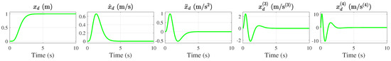
Figure 2.
Desired output to its fourth differentiation.
Table 2.
System parameters.
The altitude controller is constructed from (37). For comparison, three different position controllers are used:
- Cascade PID controller (CPID). The cascade PID control presented in Appendix A is used;
- Integral backstepping controller (IBC). The position integral backstepping controller derived from Theorem 2 is used, where the time derivatives of the virtual controls, and , are calculated by the approximated differentiator (APD) as illustrated in Appendix A;
- Analytic integral backstepping controller (AIBC). The proposed analytic integral backstepping controller presented in Theorem 3 is applied.
For CPID, the control gains are , , , , , and , respectively. The feasible solution pair that satisfies (A13) is
For IBC, the control gains are , , , , and , respectively. The resulting feasible solution pair that satisfies (43) is
The feasible solution pair that satisfies (50) is
According to (53), the matrix is
The switching gain in IBC is used to fulfill (60). The proposed AIBC is not sensitive to measurement noise. Therefore, higher control gains for the position loop in x-direction are considered to inhibit the effects of disturbances. The control gains are , , , , , , , and , respectively. The corresponding feasible solution pair ( is
From (53), the matrix is
Assume in AIBC; then, is used to satisfy (106). The step-wise procedures to implement the control law are briefly summarized as follows:
- 1.
- Given the desired position and altitude trajectory , , and their successive derivatives, and ;
- 2.
- Given the control gain pair , then determine the control force F from (37);
- 3.
- Determine the control torque M:
- (a)
- (b)
- (c)
- 4.
- Based on the calculated control force and control torque, compute the desired motor speed from (2);
- 5.
- Feed the desired speed to BLDC to generate the computed controls .
The simulation results are shown in Figure 3, Figure 4, Figure 5, Figure 6, Figure 7, Figure 8, Figure 9, Figure 10 and Figure 11. The evolution of external disturbances is shown in Figure 3. Figure 3a,b depicted the time-varying disturbances and the state-dependent viscous drags, respectively. Figure 3a implies that the properties of external disturbances are , , , , , and . The zero-mean Gaussian white noise with variances of and are considered for the measurement noise of and , respectively. The measured and actual states are illustrated in Figure 4. The actual states are collected from the integral of the system dynamics based on different control approaches. The measured states are the actual states that add the measurement noise, which will be used in the feedback control process. For the CPID, the APD is used for estimating the desired angular velocity and the desired angular acceleration from desired attitude defined in (A3). For IBC, the APD is utilized to estimate the time derivative of virtual controls, that is, estimate and from and by the APD. Both APDs with a cutoff frequency of 10 Hz are considered. On the contrary, regarding the proposed AIBC, it does not need to use the APD since the time derivatives of the virtual controls are acquired by the analytic approach.
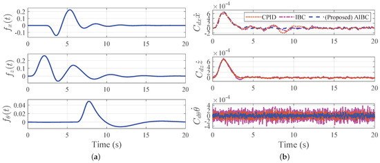
Figure 3.
Evolution of external disturbances. (a) the time-varying disturbances; (b) the state-dependent viscous drags.
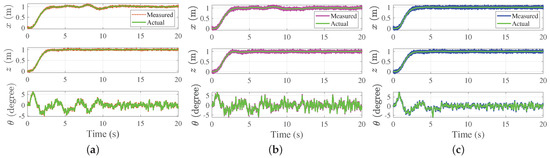
Figure 4.
Comparison of measured and actual states for different approaches. (a) CPID; (b) IBC; (c) AIBC.
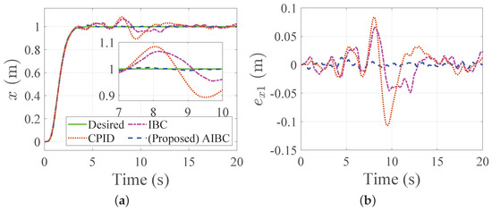
Figure 5.
Comparison of the desired command and system response in the x-direction for different approaches. (a) desired command and actual states; (b) tracking errors.
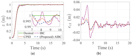
Figure 6.
Comparison of the desired command and system response in the z-direction for different approaches. (a) desired command and actual states; (b) tracking errors.
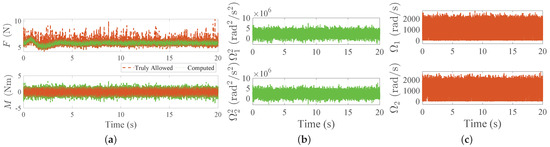
Figure 7.
Comparison of computed and truly allowed controls and rotor speeds for the CPID. (a) comparison of the computed and truly allowed controls (CPID); (b) square of computed rotor speeds; (c) truly allowed rotor speeds.
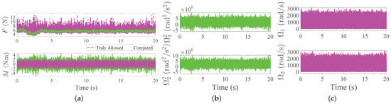
Figure 8.
Comparison of computed and truly allowed controls and rotor speeds for the IBC. (a) comparison of the computed and truly allowed controls (IBC); (b) square of computed rotor speeds; (c) truly allowed rotor speeds.
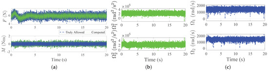
Figure 9.
Comparison of computed and truly allowed controls and rotor speeds for the proposed AIBC. (a) comparison of the computed and truly allowed controls (AIBC); (b) square of computed rotor speeds; (c) truly allowed rotor speeds.
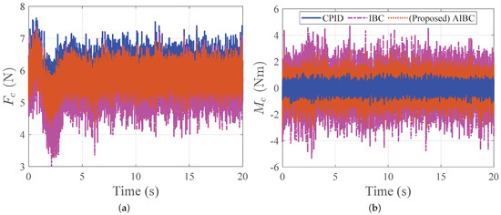
Figure 10.
Comparison of computed control force and torque for different approaches. (a) computed control force; (b) computed control torque.
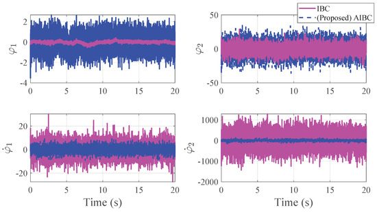
Figure 11.
Virtual controls of the IBC and AIBC.
The comparison of tracking performance for different approaches is revealed in Figure 5 and Figure 6, respectively. The corresponding root–mean–square error (RMSE) of the resulting tracking errors is summarized in Table 3. The results reveal that the proposed AIBC has the best tracking performance compared with the CPID and IBC. In fact, due to the numerical differentiations, the rotor speeds of CPID and IBC are saturated, which may induce flight instability.
Table 3.
The RMSE of tracking errors for different approaches.
Figure 7, Figure 8 and Figure 9 compare the computed and truly allowed controls for CPID, IBC, and AIBC, respectively. In Figure 7a, the computed force and torque both are denoted as a green line and are obtained from (37) and (A7); in Figure 8a, the computed force and torque both are denoted as a green line and are obtained from (37) and (54); the control laws shown in Figure 9a are obtained from (37) and (94), respectively. From the actuator configuration, the square of the computed rotor speed is computed from (4). Note that negative rotor speeds are not allowed in the practical scenarios. To meet the real situation, the negative rotor speed will be saturated by and then, by (2), the truly allowed control force and torque are generated by the rotor speeds reversely, as shown in Figure 7a, Figure 8a, and Figure 9a with a brown line, magenta line, and blue line, respectively. It can be found that the computed controls cannot be achieved due to the control signal saturation. The root of the matter is the amplified control signal due to differentiating the noisy feedback states. A similar phenomenon can be observed in Figure 8. In contrast to CPID and IBC, the proposed AIBC avoids the numerical differentiation and thereby the AIBC without inducing the control signal saturation. The computed and truly allowed controls are matched as shown in Figure 9a. Figure 10 compares the computed controls for different approaches. The results reveal that the proposed AIBC has a smooth-feasible profile, which is helpful for controller implementations.
Figure 11 shows the virtual controls of the IBC and AIBC. Results indicate that the control chattering can be significantly reduced by utilizing the proposed AIBC rather than using IBC with APD. Meanwhile, the proposed AIBC enables allowing larger control gains to improve the trajectory tracking performance because it without involves any numerical differentiation. It is worth pointing out that applying larger control gains will induce more series control chattering since the numerical differentiation is used for estimating the time derivative of virtual controls. In summary, the proposed AIBC has a smoother profile, which is superior from a control realization point of view.
5. Conclusions
In this paper, an integral backstepping control algorithm called AIBC is proposed for the quadrotor trajectory tracking demands. The related stability analysis based on the Lyapunov theory in the presence of matched as well as mismatched disturbances is also presented. Compared with the conventional cascade control algorithm, the proposed control algorithm has a better tracking performance since the developed methods consider the dynamics of the position loop and the attitude loop simultaneously. Moreover, the analytic form of the virtual control laws is derived. To alleviate the noise amplification issue, the analytic method avoids the use of numerical differentiation of the virtual control law. As a consequence, a smoother control signal can be obtained from the proposed analytic solution. In summary, the proposed AIBC control algorithm has better trajectory tracking performance and is able to generate reasonable/realizable control signals. Moreover, control saturation can be avoided as well. Simulation results reveal the effectiveness and feasibility of the presented control algorithm. The proposed methodology can be extended to a 6-DoF position control of quadrotor systems. In addition, the model uncertainties will be taken into the control design considerations in our future advanced studies.
Author Contributions
Conceptualization, C.-C.P.; methodology, Y.-R.L. and C.-C.P.; software, C.-C.C.; validation, C.-C.C.; formal analysis, Y.-R.L., C.-C.C. and C.-C.P.; investigation, C.-C.C.; resources, C.-C.P.; data curation, Y.-R.L.; writing—original draft preparation, Y.-R.L. and C.-C.C.; writing—review and editing, Y.-R.L. and C.-C.P.; visualization, C.-C.C.; supervision, C.-C.P.; project administration, C.-C.P.; funding acquisition, C.-C.P. All authors have read and agreed to the published version of the manuscript.
Funding
This work was supported by the Ministry of Science and Technology under Grant No. MOST 111-2221-E-006-170 and MOST 111-2923-E-006-004-MY3.
Data Availability Statement
The data presented in this study are available on request from the corresponding author.
Conflicts of Interest
The authors declare no conflict of interest.
Appendix A. Derivation of Conventional Cascade PID Flight Controller
One of the control methodologies for quadrotor positioning control is conventional cascade control. The cascade control designs the position controller and attitude controller separately [21]. The tracking error of the position loop will be turned into the desired attitude command and fed through it to the attitude loop. For this algorithm, the transient response of the attitude loop is ignored. However, due to the imperfections of modeling and sensing, there always exist tracking errors in the attitude loop. It leads to the precision of the positioning being limited to the tracking performance of the attitude loop. In the following, the algorithm of the conventional cascade control is presented.
Consider the x-direction dynamics of the under-actuated subsystem shown in (20):
where F has been assigned for the altitude tracking; let be the desired attitude such that the desired dynamics of (A1) can be compensated. Hence, (A1) becomes
Design in the form of (56); by inverse mapping, the desired attitude is then obtained:
To fulfill the state limitation (109), the saturation of desired attitude command is imposed. If (A3) can be achieved, it has been proven from (56)–(71) that the tracking error of the position loop is bounded by (72). The desired angular velocity and the desired angular acceleration are obtained by the approximated differentiator (APD) [21]. The transfer function of APD is given by
where is the time constant, and is the cutoff frequency.
In that follows, the attitude controller is designed to track the desired attitude. Define the tracking errors
Then, the error dynamics are
Design the control torque M as
where the control pairs . Substituting (A7) into (A6) gives the closed-loop dynamics as follows:
Define the virtual extended state as
Then, the closed-loop dynamics (A8) can be written as
where is the augmented error vector, is the augmented disturbance vector, and the closed-loop system matrix is
Applying Theorem 1, it can be concluded that the attitude tracking error will approach a region , i.e.,
where the matrices and are the feasible solution of
Appendix B. Existence Proof of Sliding Mode
In the sense of the sliding mode control, the error variable defined in (84) can be interpreted as the sliding surface. The control laws (54) and (94) are the sliding mode controller because they enable forcing the system states to reach the sliding surface . Consider the sliding dynamics (87), and select a Lyapunov function candidate as
In what follows, the IBC (54) and AIBC (94) will be respectively substituted into (A15) to show the approaching condition. First, substituting (54) into (A15) obtains
Equation (A16) indicates that the approaching condition is fulfilled by choosing the switching gain shown in (60), which should be
Then, (A16) becomes
where is a parameter to be designed. Therefore, the sliding surface exponentially converges to zero within the finite time . With the aid of (A14) and (A18), the finite time can be solved by
For (A17), it guarantees that the approaching condition is satisfied for any initial condition; then, the sliding dynamics (87) converge to zero within the finite time described in (A19). In fact, the control parameter can be arbitrarily assigned since the stability of the overall systems (47)–(49) has been guaranteed by (88) and (91). In the presence of mismatched disturbances, the switching gain (60) for any does not guarantee the approaching condition . However, when the disturbances vanish, the state and will converge until the condition such that the approaching condition holds. Eventually, the sliding motion occurs.
Next, we are going to analyze the approaching condition for the proposed AIBC (94). According to (125), replacing in (A15) with , it follows that
Therefore, by designing in (106) as
then (A21) becomes
for . As mentioned above, (A22) guarantees that the approaching condition is fulfilled for any initial condition. However, the systems (47)–(49) are still stable for any . It has been proven in (88) and (132). In the absence of mismatched disturbances, the system states converge. It implies that the will be satisfied, and then the approaching condition is fulfilled. Eventually, the sliding motion occurs.
Introducing the signum function makes it possible to reject the matched disturbance. Meanwhile, the price of robustness is the chattering phenomenon of the control signal. To avoid the chattering caused by the signum function in the control law, the saturation function [33] or a hyperbolic tangent [34,35] can be used in practical implementations. Applying the higher-order sliding mode control [35,36] may also be a feasible solution for the chattering reduction compared to the conventional sliding mode control.
References
- Bashi, O.I.D.; Hasan, W.; Azis, N.; Shafie, S.; Wagatsuma, H. Unmanned aerial vehicle quadcopter: A review. J. Comput. Theor. Nanosci. 2017, 14, 5663–5675. [Google Scholar] [CrossRef]
- Penicka, R.; Scaramuzza, D. Minimum-Time Quadrotor Waypoint Flight in Cluttered Environments. IEEE Robot. Autom. Lett. 2022, 7, 5719–5726. [Google Scholar] [CrossRef]
- Zhou, B.; Pan, J.; Gao, F.; Shen, S. RAPTOR: Robust and Perception-Aware Trajectory Replanning for Quadrotor Fast Flight. IEEE Trans. Robot. 2021, 37, 1992–2009. [Google Scholar] [CrossRef]
- Peng, C.C.; Cheng-Yu, W. Design of Constrained Dynamic Path Planning Algorithms in Large-Scale 3D Point Cloud Maps for UAVs. J. Comput. Sci. 2023, 67, 101944. [Google Scholar] [CrossRef]
- Falanga, D.; Kleber, K.; Scaramuzza, D. Dynamic obstacle avoidance for quadrotors with event cameras. Sci. Robot. 2020, 5, eaaz9712. [Google Scholar] [CrossRef]
- Yañez-Badillo, H.; Beltran-Carbajal, F.; Tapia-Olvera, R.; Favela-Contreras, A.; Sotelo, C.; Sotelo, D. Adaptive Robust Motion Control of Quadrotor Systems Using Artificial Neural Networks and Particle Swarm Optimization. Mathematics 2021, 9, 2367. [Google Scholar] [CrossRef]
- Nettari, Y.; Labbadi, M.; Kurt, S. Adaptive Robust Finite-Time Tracking Control for Quadrotor Subject to Disturbances. Adv. Space Res. 2022, in press. [CrossRef]
- Betancourt, J.; Castillo, P.; Garcia, P.; Balaguer, V.; Lozano, R. Robust bounded control scheme for quadrotor vehicles under high dynamic disturbances. preprint 2022. [CrossRef]
- Madani, T.; Benallegue, A. Backstepping control for a quadrotor helicopter. In Proceedings of the 2006 IEEE/RSJ International Conference on Intelligent Robots and Systems, Beijing, China, 9–15 October 2006; pp. 3255–3260. [Google Scholar] [CrossRef]
- Jasim, W.; Gu, D. Integral backstepping controller for quadrotor path tracking. In Proceedings of the 2015 International Conference on Advanced Robotics (ICAR), Istanbul, Turkey, 27–31 July 2015; pp. 593–598. [Google Scholar] [CrossRef]
- Zhou, L.; Zhang, J.; She, H.; Jin, H. Quadrotor UAV flight control via a novel saturation integral backstepping controller. Automatika 2019, 60, 193–206. [Google Scholar] [CrossRef]
- Labbadi, M.; Cherkaoui, M. Robust adaptive backstepping fast terminal sliding mode controller for uncertain quadrotor UAV. Aerosp. Sci. Technol. 2019, 93, 105306. [Google Scholar] [CrossRef]
- Koksal, N.; An, H.; Fidan, B. Backstepping-based adaptive control of a quadrotor UAV with guaranteed tracking performance. ISA Trans. 2020, 105, 98–110. [Google Scholar] [CrossRef] [PubMed]
- Xuan-Mung, N.; Hong, S.K. Robust Backstepping Trajectory Tracking Control of a Quadrotor with Input Saturation via Extended State Observer. Appl. Sci. 2019, 9, 5184. [Google Scholar] [CrossRef]
- Govea-Vargas, A.; Castro-Linares, R.; Duarte-Mermoud, M.A.; Aguila-Camacho, N.; Ceballos-Benavides, G.E. Fractional Order Sliding Mode Control of a Class of Second Order Perturbed Nonlinear Systems: Application to the Trajectory Tracking of a Quadrotor. Algorithms 2018, 11, 168. [Google Scholar] [CrossRef]
- Niu, Y.; Ban, H.; Zhang, H.; Gong, W.; Yu, F. Nonsingular Terminal Sliding Mode Based Finite-Time Dynamic Surface Control for a Quadrotor UAV. Algorithms 2021, 14, 315. [Google Scholar] [CrossRef]
- Zhao, J.; Wang, X.; Gao, G.; Na, J.; Liu, H.; Luan, F. Online Adaptive Parameter Estimation for Quadrotors. Algorithms 2018, 11, 167. [Google Scholar] [CrossRef]
- Liu, J.; Gai, W.; Zhang, J.; Li, Y. Nonlinear adaptive backstepping with ESO for the quadrotor trajectory tracking control in the multiple disturbances. Int. J. Control. Autom. Syst. 2019, 17, 2754–2768. [Google Scholar] [CrossRef]
- Chovancová, A.; Fico, T.; Chovanec, Ľ.; Hubinsk, P. Mathematical Modelling and Parameter Identification of Quadrotor (a survey). Procedia Eng. 2014, 96, 172–181. [Google Scholar] [CrossRef]
- Ventura Diaz, P.; Yoon, S. High-fidelity computational aerodynamics of multi-rotor unmanned aerial vehicles. In Proceedings of the 2018 AIAA Aerospace Sciences Meeting, Kissimmee, FL, USA, 8–12 January 2018; p. 1266. [Google Scholar]
- Moreno-Valenzuela, J.; Pérez-Alcocer, R.; Guerrero-Medina, M.; Dzul, A. Nonlinear PID-Type Controller for Quadrotor Trajectory Tracking. IEEE/ASME Trans. Mechatron. 2018, 23, 2436–2447. [Google Scholar] [CrossRef]
- Jia, Z.; Yu, J.; Mei, Y.; Chen, Y.; Shen, Y.; Ai, X. Integral Backstepping Sliding Mode Control for Quadrotor Helicopter under External Uncertain Disturbances. Aerosp. Sci. Technol. 2017, 68, 299–307. [Google Scholar] [CrossRef]
- Ríos, H.; Falcón, R.; González, O.A.; Dzul, A. Continuous Sliding-Mode Control Strategies for Quadrotor Robust Tracking: Real-Time Application. IEEE Trans. Ind. Electron. 2019, 66, 1264–1272. [Google Scholar] [CrossRef]
- Zhang, Z.; Wang, F.; Guo, Y.; Hua, C. Multivariable sliding mode backstepping controller design for quadrotor UAV based on disturbance observer. Sci. China Inf. Sci. 2018, 61, 1–16. [Google Scholar] [CrossRef]
- Goodarzi, F.; Lee, D.; Lee, T. Geometric nonlinear PID control of a quadrotor UAV on SE(3). In Proceedings of the 2013 European Control Conference (ECC), Zurich, Switzerland, 17–19 July 2013; pp. 3845–3850. [Google Scholar] [CrossRef]
- Demirhan, M.; Premachandra, C. Development of an Automated Camera-Based Drone Landing System. IEEE Access 2020, 8, 202111–202121. [Google Scholar] [CrossRef]
- Piponidis, M.; Aristodemou, P.; Theocharides, T. Towards a Fully Autonomous UAV Controller for Moving Platform Detection and Landing. In Proceedings of the 2022 35th International Conference on VLSI Design and 2022 21st International Conference on Embedded Systems (VLSID), Bangalore, India, 26 February–2 March 2022; pp. 180–185. [Google Scholar] [CrossRef]
- Peng, C.C.; Li, Y.; Chen, C.L. A robust integral type backstepping controller design for control of uncertain nonlinear systems subject to disturbance. Int. J. Innov. Comput. Inf. Control 2011, 7, 2543–2560. [Google Scholar]
- Meslouli, I.; Kahouadji, M.; Choukchou-Braham, A.; Bensalah, C.; Mokhtari, M.R.; Cherki, B. Experimental validation of quaternion based integral backstepping design for attitude tracking. In Proceedings of the 2018 6th International Conference on Control Engineering & Information Technology (CEIT), Istanbul, Turkey, 25–27 October 2018; pp. 1–6. [Google Scholar] [CrossRef]
- Peng, C.C.; Chen, T.Y. A recursive low-pass filtering method for a commercial cooling fan tray parameter online estimation with measurement noise. Measurement 2022, 205, 112193. [Google Scholar] [CrossRef]
- Peng, C.C.; Su, C.Y. Modeling and Parameter Identification of a Cooling Fan for Online Monitoring. IEEE Trans. Instrum. Meas. 2021, 70, 1–14. [Google Scholar] [CrossRef]
- Zhang, F. The Schur Complement and Its Applications; Springer Science & Business Media: Berlin/Heidelberg, Germany, 2006; Volume 4. [Google Scholar]
- Aguilar-Ibañez, C. Stabilization of the PVTOL aircraft based on a sliding mode and a saturation function. Int. J. Robust Nonlinear Control. 2017, 27, 843–859. [Google Scholar] [CrossRef]
- Shi, Z.; Deng, C.; Zhang, S.; Xie, Y.; Cui, H.; Hao, Y. Hyperbolic Tangent Function-Based Finite-Time Sliding Mode Control for Spacecraft Rendezvous Maneuver Without Chattering. IEEE Access 2020, 8, 60838–60849. [Google Scholar] [CrossRef]
- Khandekar, A.A.; Malwatkar, G.M.; Patre, B.M. Discrete Sliding Mode Control for Robust Tracking of Higher Order Delay Time Systems with Experimental Application. ISA Trans. 2013, 52, 36–44. [Google Scholar] [CrossRef]
- Defoort, M.; Floquet, T.; Kokosy, A.; Perruquetti, W. A Novel Higher Order Sliding Mode Control Scheme. Syst. Control Lett. 2009, 58, 102–108. [Google Scholar] [CrossRef]
Disclaimer/Publisher’s Note: The statements, opinions and data contained in all publications are solely those of the individual author(s) and contributor(s) and not of MDPI and/or the editor(s). MDPI and/or the editor(s) disclaim responsibility for any injury to people or property resulting from any ideas, methods, instructions or products referred to in the content. |
© 2023 by the authors. Licensee MDPI, Basel, Switzerland. This article is an open access article distributed under the terms and conditions of the Creative Commons Attribution (CC BY) license (https://creativecommons.org/licenses/by/4.0/).