Abstract
A new control technique known as inverted error deviation (IED) control is incorporated into the main DC-link capacitor voltage regulation algorithm of a three-level neutral-point diode clamped (NPC) inverter-based shunt active power filter (SAPF) to enhance its performance in overall DC-link voltage regulation so as to improve its harmonics mitigation performances. In the SAPF controller, DC-link capacitor voltage regulation algorithms with either the proportional-integral (PI) or fuzzy logic control (FLC) technique have played a significant role in maintaining a constant DC-link voltage across the DC-link capacitors. However, both techniques are mostly operated based on a direct voltage error manipulation approach which is insufficient to address the severe DC-link voltage deviation that occurs during dynamic-state conditions. As a result, the conventional algorithms perform poorly with large overshoot, undershoot, and slow response time. Therefore, the IED control technique is proposed to precisely address the DC-link voltage deviation. To validate effectiveness and feasibility of the proposed algorithm, simulation work in MATLAB-Simulink and experimental implementation utilizing a TMS320F28335 Digital Signal Processor (DSP) are performed. Moreover, conventional algorithms with PI and FLC techniques are tested too for comparison purposes. Both simulation and experimental results are presented, confirming the improvement achieved by the proposed algorithm in terms of accuracy and dynamic response in comparison to the conventional algorithms.
1. Introduction
Harmonics mitigation and reactive power compensation have become increasingly essential in power distribution systems due primarily to significant increase of current harmonics resulted from widespread use of nonlinear loads such as power converters, adjustable speed drives and uninterruptible power supplies. The presence of current harmonics not only degrades overall system efficiency by worsening its power factor (PF) performance, but also causes other associated problems such as equipment overheating, failures of sensitive devices and capacitor blowing [1,2,3]. Therefore, it is compulsory to minimize the harmonics level of a power system.
Various mitigation solutions such as passive filters, active power filters and hybrid filters have been proposed [4,5,6]. Nevertheless, shunt-typed active power filter (SAPF) [4,5,6,7,8] is the most effective mitigation tool to mitigate current harmonics. Additionally, it also provides reactive power compensation meant for improving PF performances [7,8,9,10,11,12]. Typically, SAPF performs by injecting opposition current (simply known as injection current) back to the polluted power system to recover the sinusoidal characteristics of the source current with fundamental frequency.
Previously, most established SAPFs employ a standard two-level inverter topology in their designs. However, multilevel inverters which have been reported to possess better advantages than traditional two-level inverters [13,14,15] in terms of output voltage quality and power losses, are accepted as a better alternative. The unique ability of multilevel inverters in providing output voltage with multiple levels reduces the harmonics content of the generated output signal. Generally, the higher the voltage levels an inverter produces, the lower the harmonic contents and power losses it provides. However, in the context of SAPFs, the multilevel inverters employed are mostly limited to three-level [3,16,17] due primarily to high degree of complexity in controller design which involves higher number of switching states and greater severity of imbalance in capacitor voltages as the number of level increases.
Among various established multilevel inverter topologies, the neutral-point diode clamped (NPC) topology provides the best performance in terms of capacitor voltage balancing [13]. In a three-level NPC inverter, the voltage across the two splitting DC-link capacitors must equally be maintained as half of the overall DC-link voltage [3,15,17] so that a balanced injection current can be generated to properly mitigate the current harmonics. Moreover, if the voltages are unbalanced, there is a high risk of premature switches failure due to over-stresses, and further increment to the total harmonics distortion (THD). Meanwhile, in the context of inverter-based SAPF, the overall DC-link voltage must constantly be maintained at a level which is high enough to precisely inject the desired injection current back to the polluted power system.
Conventionally, overall DC-link voltage is regulated via a direct voltage error manipulation approach where the difference (voltage error) between the actual overall DC-link voltage and its desired reference voltage is directly utilized by either a proportional-integral (PI) controller [18,19,20,21,22,23] or fuzzy logic controller (FLC) [18,19,20,21,22,24,25,26,27] to produce an estimated output which is assumed to be the main control signal for regulating the DC-link voltage. Nevertheless, the DC-link capacitor voltage regulation algorithm with PI technique is more widely used due to its simple implementation features. However, it performs with high overshoot [18,19,20,23,28] and large time delay [18,20,21,22,23,28] under dynamic-state conditions. Besides, it requires a precise linear mathematical model which is difficult to obtain and may not perform accordingly under load disturbances and parameter variations [20,21]. Moreover, the performance of a PI controller strictly depends on the value of its tuned proportional gain and integral gain parameters which are normally obtained through a tedious heuristic approach.
Further improvement based on artificial intelligence (AI) technique has been implemented where FLC is utilized to eliminate the reliance on PI controller. By incorporating the advantages of FLC, performance of SAPF in term of overall DC-link voltage regulation has significantly improved [18,20,21,22]. FLC is famous for its superior robustness, speed and accuracy [19,20,21,24,29]. It is an adaptive mechanism which operates based on linguistic control (if-then) rules to approximate a function [19,24,29]. Consequently, it is able to perform effectively with imprecise inputs, handle nonlinear system with parameter variations, and is possible to be designed without knowing the exact mathematical model of the system [20,21,24,25,29], thereby overcoming the limitations of PI technique. However, in the context of overall DC-link voltage regulation, the FLC techniques employed are mostly implemented with high number of fuzzy membership functions and rules [18,19,20,21,22,24,25,26,27], thereby imposing great computational burden to the controller.
Besides, the DC-link capacitor voltage regulation algorithm with FLC technique is still operated based on direct voltage error manipulation approach, and thus cannot completely eliminate the severe DC-link voltage deviation (overshoot and undershoot) that occurs during dynamic-state conditions. The control technique based on a direct voltage error manipulation approach is executed by processing the entire voltage error signal disregarding any voltage deviations to the overall DC-link voltage which may occur throughout the operation of SAPF. In other words, operation based on a direct control approach limits the capability of the designed DC-link capacitor voltage regulation algorithm.
Therefore, this paper presents a DC-link capacitor voltage regulation algorithm with Inverted Error Deviation (IED) control which operates based on an indirect voltage error manipulation approach, to enhance performance in overall DC-link voltage regulation under both steady-state and dynamic-state conditions. The design concept and effectiveness of the proposed algorithm are verified using MATLAB-Simulink. For performance comparison, conventional algorithms with PI and FLC techniques are developed too, and all algorithms are tested under both steady-state and dynamic-state conditions. Moreover, a laboratory prototype is developed with the proposed algorithm downloaded in digital signal processor (DSP) for further validation.
The rest of the paper is organized as follows: in Section 2, the proposed SAPF with control strategies is described. Section 3 presents the details of the harmonics extraction algorithm used in the SAPF. In Section 4, the proposed DC-link capacitor voltage regulation algorithm with IED control is presented with clear illustration. The simulation and experimental results are presented, and discussed in Section 5 and Section 6 respectively, showing effectiveness of the proposed algorithm in comparison to the conventional algorithms. The paper ends with a brief conclusion in Section 7 by summarizing significant contributions of this work.
2. Shunt Active Power Filter (SAPF) with Control Strategies
The proposed three-phase SAPF utilizing a three-level NPC inverter which is connected at point of common coupling (PCC) between three-phase source and nonlinear load is shown in Figure 1. The nonlinear load consists of a full bridge rectifier which is recognized as one of the worst sources of harmonics [30,31] in electrical system. The rectifier is further connected to three types of loads: capacitive, inductive and resistive loads. Meanwhile, the SAPF’s controller composes of harmonics extraction, DC-link capacitor voltage regulation, synchronizer, neutral-point voltage deviation control, and current control (switching) algorithms.
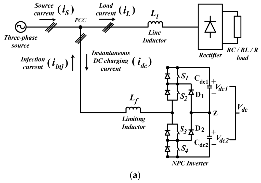
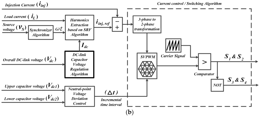
Figure 1.
The proposed three-phase three-level NPC inverter-based SAPF: (a) circuit diagram, and (b) control strategies.
This paper focuses mainly on DC-link capacitor voltage regulation algorithm. From the literature, in order to ensure proper generation of injection current , the overall DC-link voltage is set according to the following requirement [20,32,33,34,35]:
where represents the source voltage, and represents the maximum output voltage of SAPF.
Meanwhile, the minimum capacitance value for each capacitor can be determined as follows [36,37,38,39]:
where represents the injection current, and represents the maximum voltage ripple allowed on DC-link capacitors.
For the harmonics extraction algorithm, the synchronous reference frame (SRF) principle [12,31,40] is used. Meanwhile, a synchronizer is utilized to provide referencing signals to the harmonics extraction algorithm. Furthermore, voltage balancing of splitting DC-link capacitors is achieved via a neutral-point voltage deviation control algorithm [41,42,43] which ensures equal inflow and outflow of current at the neutral point Z, by adjusting the activation time of each switching device according to the instantaneous voltage across both splitting DC-link capacitors ( and ). Finally, the switching control is accomplished through a 25 kHz Space Vector PWM (SVPWM) [15,16,41,44,45] switching algorithm.
3. Harmonics Extraction Algorithm
Harmonics extraction based on the SRF algorithm as shown in Figure 2, is accomplished through a series of mathematical calculations of three-phase load current which is conducted in direct-quadrature-zero frame.
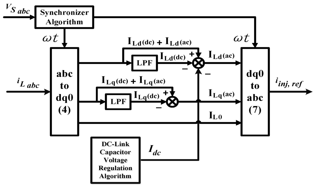
Figure 2.
Harmonics extraction based on SRF algorithm.
The measured load current in three-phase frame is transformed into its corresponding frame by means of a Park transformation given as:
where is the synchronization angle representing the angular position of synchronous reference frame which is delivered by a synchronizer.
Under influence of the nonlinear loads, the actual and components are polluted by the generated current harmonics and thus resulting in the formation of new current relationship given as:
where and represent the fundamental () and harmonics () components of load current in frame respectively. A similar relation holds for load current in frame and .
In the frame, the fundamental component of load current will appear as a signal and meanwhile the current harmonics generated by nonlinear loads which is represented by components, will appear as ripples. For the purpose of harmonics extraction, both and components are required for reference current generation. Generally, the components are obtained through indirect identification approach [46] where a tuned numerical low pass filter (LPF) is usually employed to detect the component which is then being removed from the actual load current in frame [12,31,40]. This approach can be represented as:
In the context of the SRF principle, the choice of the filter used is one of the main factors that determine the performance of the designed harmonics extraction algorithm. The filter used is a second order Butterworth-typed LPF with a cutting frequency of 10 Hz. This type of filter is recognized as the best “all-round” filter which provides fast dynamic response with acceptable filtering features [12,31,40].
Once the components ( and ) are obtained, inverse Park transformation as shown in (7) is performed to transform the components back to their corresponding three-phase harmonic current in frame, forming the required reference injection current :
4. DC-Link Capacitor Voltage Regulation Algorithm
In order to deliver better understanding on the proposed DC-link capacitor voltage regulation algorithm, and at the same time, for proper comparison, the details of the conventional algorithm utilizing the PI and FLC techniques are first presented serving as a benchmark for improvement. Next, with reference to the conventional algorithms, the proposed DC-link capacitor voltage regulation algorithm with inverted error deviation (IED) control is elaborated, highlighting the improvements made.
4.1. Conventional DC-Link Capacitor Voltage Regulation Algorithm with PI and FLC Techniques
Generally, overall DC-link voltage is regulated by controlling the real power drawn by SAPF throughout its switching operation. The voltage regulation process is said to have accomplished when the real power drawn by the SAPF is made equal to its switching losses. Therefore, in order to constantly maintain proper function of SAPF, magnitude of the generated reference current must suitably be adjusted by manipulating the magnitude of a control variable known as instantaneous DC charging current (refer to Figure 1 and Figure 2) which is generated based on the difference between overall DC-link voltage and its desired reference value, so that a precise amount of real power can be drawn by SAPF to compensate its potential losses.
As mentioned in Section 1, the PI technique is the most widely utilized technique in the area of DC-link capacitor voltage regulation. Based on this technique, the voltage error resulting from the difference between overall DC-link voltage ( + ) and its reference voltage is directly manipulated by a PI controller to approximate the magnitude . The control approach can be summarized as follows:
Figure 3a shows the control structure of conventional DC-link capacitor voltage regulation with PI technique. Meanwhile, the minimum value of design parameters used in the PI technique can be obtained as follows [29]:
where is the proportional gain, is the integrator gain, is the capacitance value of each splitting capacitor, is the damping factor fixed at 0.707, and is the angular frequency. Further adjustment and tuning are performed in heuristic manner to improve control performance.
Figure 3.
Conventional DC-link capacitor voltage regulation algorithm with (a) PI; and (b) FLC techniques.
On the other hand, the control structure of conventional DC-link capacitor voltage regulation with FLC technique is shown in Figure 3b. In this algorithm, FLC is employed to eliminate the reliance on PI controller. The FLC technique employed depends on voltage error and change of voltage error with sample time given in (12) and (13), respectively, to approximate magnitude :
Generally, FLC operation involves four processes, starting with fuzzification, followed by fuzzy rule base and inference interpretation, and end with defuzzification. During fuzzification, the formulated numerical and variables are converted into their corresponding linguistic representation, according to their respective fuzzy membership functions.
All input conditions will be processed by a fuzzy inference mechanism to generate the most appropriate fuzzified output according to the designed fuzzy rule base table which composes a collection of simple linguistic “If A and B, Then C” rules. The most commonly applied inference mechanism is known as Mamdani-style inference mechanism [19,20,21,29,47]. The generated fuzzified output is converted back to its corresponding numerical magnitude via defuzzification process. Most FLC systems use the famous centroid of area (COA) defuzzification method [19,29,47,48,49] as it provides a good average feature in determining the best output result. The fuzzy membership functions and rule base for FLC technique which are commonly applied in conventional DC-link capacitor voltage regulation algorithm are shown in Figure 4a and Table 1 respectively.
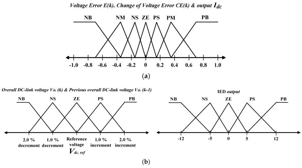
Figure 4.
Fuzzy membership functions for input and output variables used in FLC: (a) conventional algorithm with FLC technique [24,26], and (b) proposed algorithm with IED control.

Table 1.
Fuzzy rule base for the conventional algorithm with FLC technique [20,21,26,27].
4.2. Proposed DC-Link Capacitor Voltage Regulation Algorithm with IED Control
In order to precisely address all possible voltage deviations which may occur to the overall DC-link voltage during dynamic-state conditions, the IED control technique is proposed and incorporated into the main DC-link capacitor voltage regulation algorithm. Generally, magnitude will be maintained at zero when the overall DC-link voltage is successfully regulated at its desired value. However, during dynamic-state conditions, the overall DC-link voltage may deviate from its desired value and thus resulting in sudden increase (overshoot) or decrease (undershoot) of voltage error . The proposed algorithm with IED control as shown in Figure 5 is performed by generating an opposition signal (IED signal) to cancel out all deviations that occur to the voltage error . This results in formation of regulated voltage error which is treated as the desired . The control approach can be summarized as follows:
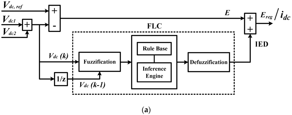
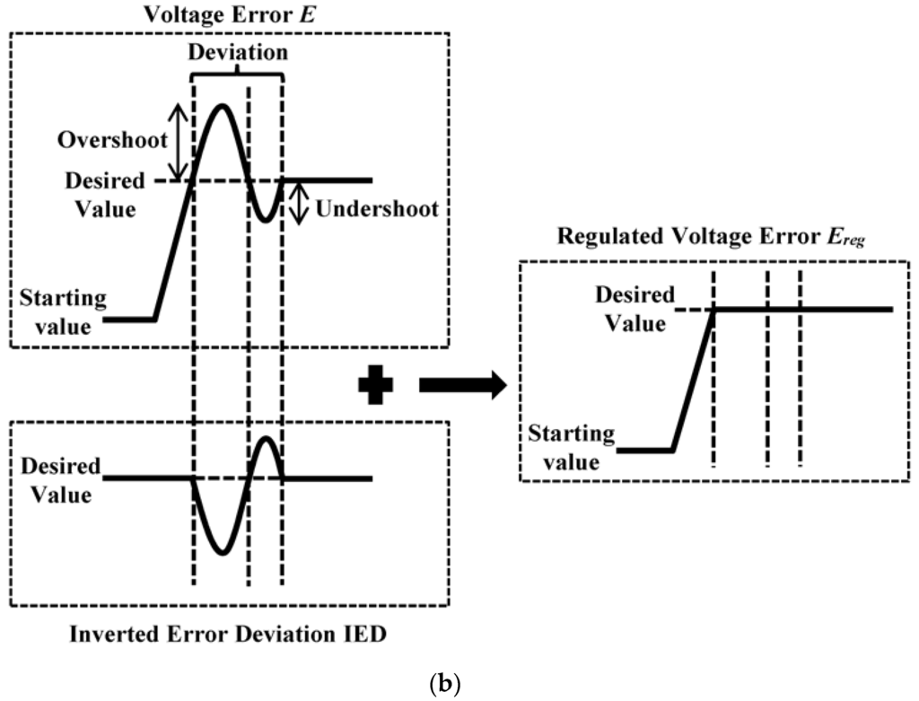
Figure 5.
Proposed DC-link capacitor voltage regulation algorithm with IED control: (a) control structure; and (b) working principle.
The incorporation of the IED control technique provides important insight into development of indirect voltage error manipulation approach, where an alternative route is formed to indirectly manipulate voltage error , focusing solely on minimizing the effects of voltage deviations (overshoot and undershoot) that occur to the overall DC-link voltage during dynamic-state conditions. In other words, the IED control technique does not disturb the normal regulation process of the overall DC-link voltage . It will only be executed in response to voltage deviations that occur after the overall DC-link voltage reaches its desired value.
In contrast to conventional algorithms which perform by processing entirely the resulted voltage error , the proposed algorithm with IED control which performs by considering only the voltage error deviations, reduces the required computational efforts and simultaneously improves dynamic performance in overall DC-link voltage regulation. At any instance, if voltage error deviation ( 0) occurs, the degree of deviation will be processed by the proposed algorithm to generate a corresponding IED for mitigating the effects of voltage error deviation. If overshoot ( 0) occurs, a corresponding negative IED will be produced to counteract the sudden increase of . Meanwhile, if undershoot ( 0) occurs, IED will be increased to a level that is most appropriate in dealing with the sudden drop of .
To ensure precise generation of IED, the FLC technique is employed. In contrast to FLC techniques applied in the conventional algorithms which perform based on and input variables, FLC technique applied in the proposed algorithm makes use of overall DC-link voltage and previous overall DC-link voltage to approximate the required IED. The membership functions and rule base for FLC technique applied in the proposed algorithm are shown in Figure 4b and Table 2, respectively. The fuzzy sets are selected according to the degree of voltage deviation which may occur to the overall DC-link voltage throughout the operation of SAPF. The selected fuzzy sets must possess certain sensitivity (level of fuzziness) which is sufficient enough to represent all the voltage deviation conditions. Low number of fuzzy sets may be insufficient to describe the characteristics of a signal. In contrast, large number of fuzzy sets provides much better results but high amount of fuzzy membership functions and rules are difficult to be developed.
Table 2.
Fuzzy rule base for the proposed algorithm with IED control.
In this work, 5 × 5 membership functions with 25 control rules are considered for the proposed algorithm. The higher number of membership functions are not considered as high usage of membership functions impose great computation burden to the controller, which undoubtedly intensify the difficulties for practical implementation. Moreover, a combination of triangular and trapezoidal membership functions is applied. These types of membership functions are famous for their simple implementation features together with minimal computational efforts [19,21,26,50].
The mapping of membership functions and control rules requires a thorough understanding of the behavior of the signal to be controlled. It is performed based on open-loop real data [29] of the overall DC-link voltage with reference to the systematic FLC design approach described in [51]. Further adjustment and tuning are performed in heuristic manner to improve control performance. With utilization of the selected membership functions and control rules in the proposed algorithm, the overall DC-link voltage can be accurately regulated.
5. Simulation Results
The three-phase three-level NPC inverter-based SAPF utilizing the proposed DC-link capacitor voltage algorithm with inverted error deviation (IED) control is tested and evaluated in MATLAB-Simulink. Simulation work is conducted under both steady-state and dynamic-state conditions which involve three types of nonlinear loads. The first nonlinear load is constructed using a three-phase uncontrolled bridge rectifier feeding 20 Ω resistor and 2200 μF capacitor connected in parallel (capacitive). The second nonlinear load is developed using similar rectifier feeding a series connected 50 Ω resistor and 50 mH inductor (inductive). The third nonlinear load is developed using similar rectifier feeding a 20 Ω resistor (resistive). Furthermore, the conventional DC-link capacitor voltage regulation algorithm with PI and FLC techniques are also tested for comparison purposes. The key specifications of the proposed SAPF and all the DC-link capacitor voltage regulation algorithms are summarized in Table 3 and Table 4, respectively.
Table 3.
Proposed parameters for SAPF.
Table 4.
Parameter specifications for each DC-link capacitor voltage regulation algorithm.
Under steady-state condition, each DC-link capacitor voltage regulation algorithm is evaluated in terms of voltage regulation accuracy and mitigation performance (THD value) of SAPF. For accuracy analysis, a new performance parameter known as percentage of accuracy (% ACC) is applied. It is defined as:
where and represent the reference and the average value of overall DC-link voltage, respectively.
Meanwhile, under dynamic-state conditions, the performance parameters involved are overshoot, undershoot, and response time. For this analysis, two dynamic-state conditions are created by changing the nonlinear loads from capacitive to inductive and inductive to resistive respectively.
5.1. Steady-State Condition
Simulation results of SAPF utilizing the proposed algorithm with IED control which includes three-phase source voltage , load current , injection current , and source current for capacitive, inductive, and resistive loads are shown in Figure 6. Meanwhile, THD values of mitigated source current resulted from SAPF utilizing each DC-link capacitor voltage regulation algorithm are recorded in Table 5. The findings clearly show that SAPF utilizing each DC-link capacitor voltage regulation algorithm has successfully removed the current harmonics generated by all nonlinear loads, resulting in THD values of far below 5%, complying with the limit set by IEEE Standard 519-2014 [52]. However, SAPF utilizing the proposed algorithm with IED control performs outstandingly by achieving the lowest THD values for all nonlinear loads. Furthermore, it can be observed that the mitigated source current is working in phase with the source voltage for all nonlinear loads, thereby leading to almost unity power factor.
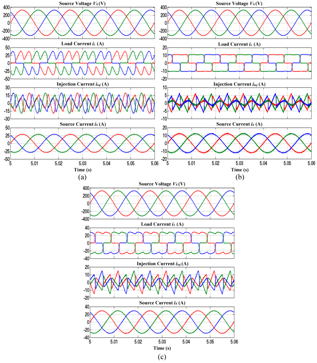
Figure 6.
Simulation results of SAPF utilizing the proposed algorithm with IED control which include three-phase source voltage , load current , injection current and source current for (a) capacitive; (b) inductive and (c) resistive loads.
Table 5.
THD values of source current in all phases resulted from SAPF utilizing each DC-link capacitor voltage regulation algorithm (Simulation Result).
On the other hand, simulation results on voltage regulation performances of each DC-link capacitor voltage regulation algorithm for capacitive, inductive and resistive loads are shown in Figure 7. Meanwhile, the corresponding % ACC values are summarized in Table 6. From the findings, it is clear that all voltage regulation algorithms have successfully regulated the overall DC-link voltage . However, they perform differently in term of accuracy. The proposed algorithm with IED control performs outstandingly by regulating the overall DC-link voltage with the highest accuracy (% ACC = 100%) for all nonlinear loads. On the other hand, the conventional algorithm with PI technique performs poorly by producing a regulated voltage of 0.25 V lower (% ACC = 99.97%), 0.05 V higher (% ACC = 99.99%), and 0.25 V higher (% ACC = 99.97%) than the desired value for capacitive, inductive and resistive loads respectively. Meanwhile, conventional algorithm with FLC technique shows the worst performance by producing a regulated voltage of 0.5 V (% ACC = 99.94%), 0.1 V (% ACC = 99.98%), and 0.5 V (% ACC = 99.94%) higher than the desired value for capacitive, inductive and resistive loads respectively. Therefore, in term of overall DC-link voltage regulation under steady-state conditions, all voltage regulation algorithms have proven to perform with high accuracy. However, the proposed algorithm with IED control performs outstandingly by achieving an accuracy of 0.01%–0.06% higher than the conventional algorithms.
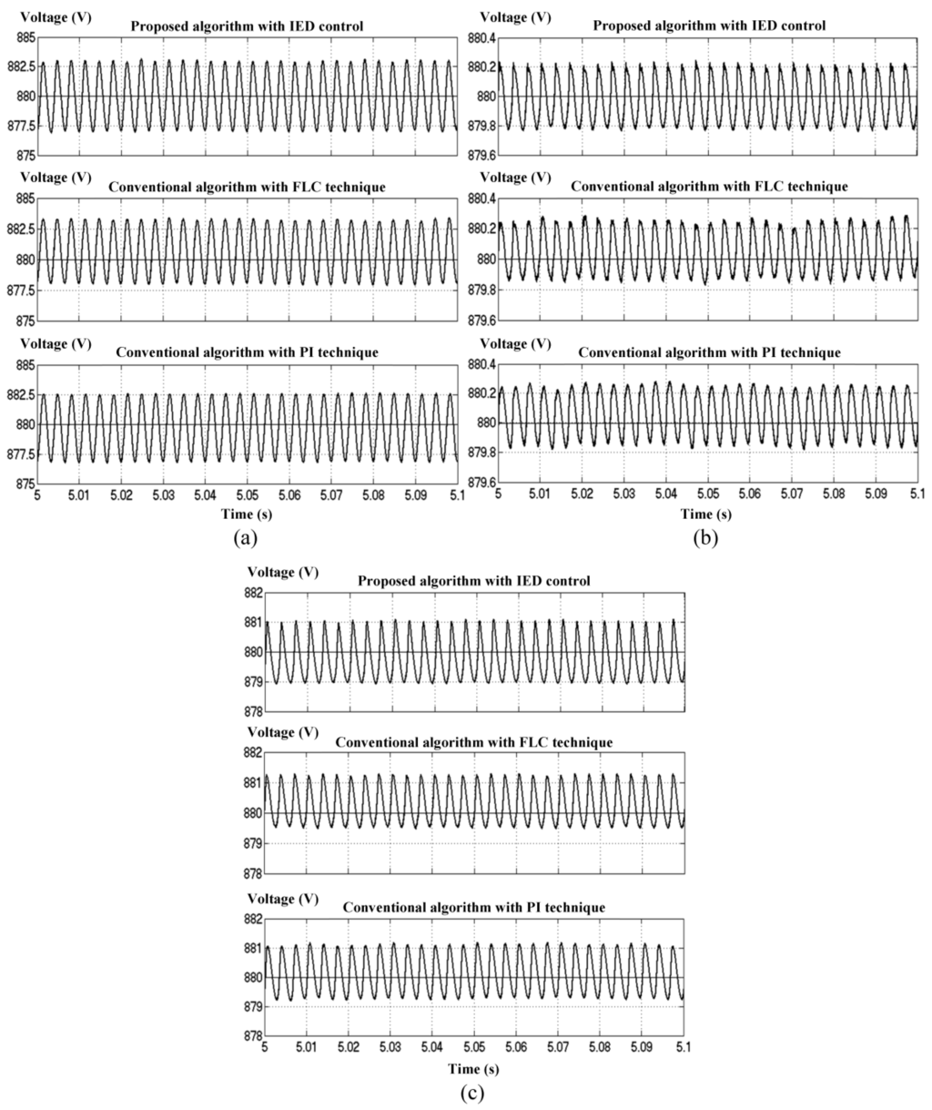
Figure 7.
Performance comparison of DC-link capacitor voltage regulation algorithms with reference voltage of 880 V for steady-state conditions of (a) capacitive; (b) inductive and (c) resistive loads.
Table 6.
Voltage regulation performance of each DC-link capacitor voltage regulation algorithm (simulation result).
5.2. Dynamic-State Condition
The responses of each DC-link capacitor voltage regulation algorithm towards dynamic-state conditions of capacitive to inductive and inductive to resistive are shown in Figure 8 and Figure 9, respectively. Meanwhile, the corresponding dynamic performances are summarized in Table 6. For capacitive to inductive, the proposed algorithm with IED control performs outstandingly with the lowest overshoot of 4 V, no undershoot, and the fastest response time of 0.020 s. Meanwhile, the conventional algorithm with FLC technique performs poorly with overshoot of 13 V, no undershoot, and response time of 0.025 s. The worst dynamic performance is shown by the conventional algorithm with PI technique which performs with largest overshoot of 35 V, undershoot of 2 V, and response time of 1.500 s. Similarly, for inductive to resistive, the proposed algorithm with IED control performs outstandingly with the lowest undershoot of 5 V, no overshoot, and the fastest response time of 0.020 s. Meanwhile, the worst dynamic performance is shown by the conventional algorithm with PI technique which performs with largest undershoot of 39 V, overshoot of 2 V, and response time of 1.500 s. Although conventional algorithm with FLC technique is observed to perform better than PI technique, it still performs with significant undershoot of 13 V, and response time of 0.025 s.
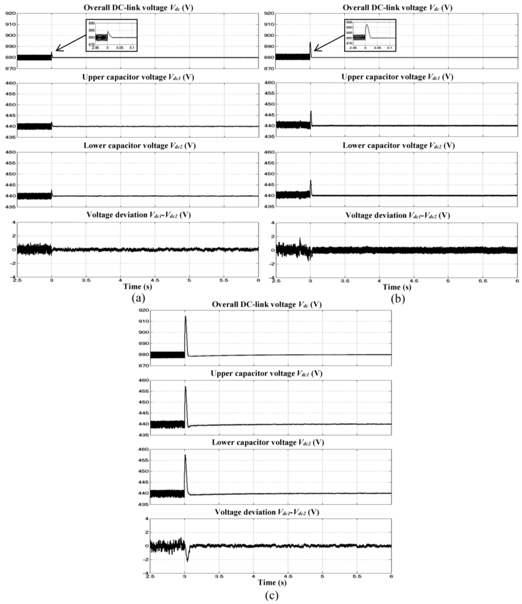
Figure 8.
Simulation results of SAPF which include overall DC-link voltage , splitting DC-link capacitor voltages ( and ) and neutral-point voltage deviation () for dynamic-state condition of capacitive to inductive load obtained using (a) the proposed algorithm with IED control; and (b) the conventional algorithm with FLC and (c) PI techniques.
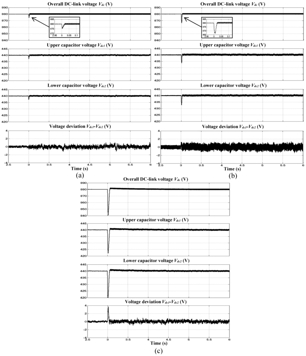
Figure 9.
Simulation results of SAPF which include overall DC-link voltage , splitting DC-link capacitor voltages ( and ) and neutral-point voltage deviation () for dynamic-state condition of inductive to resistive load obtained using (a) the proposed algorithm with IED control; and (b) the conventional algorithm with FLC and (c) PI techniques.
Moreover, it is revealed from Figure 10 and Figure 11 that the responses of mitigated source current during dynamic-state conditions are affected by the dynamic responses of DC-link capacitor voltage regulation algorithms. For instance, as shown in Figure 10c and Figure 11c, high overshoot and undershoot demonstrated by conventional algorithm with PI technique, significantly reduces and increases the magnitude of mitigated source current respectively. Additionally, under both dynamic-state conditions, its poor dynamic responses have imposed additional time delay (response time of 0.06 s) towards mitigation performance of SAPF. Meanwhile, as shown in Figure 10b and Figure 11b, the reduced overshoot and undershoot demonstrated by conventional algorithm with FLC technique still cause noticeable reduction and increment to the magnitude of mitigated source current respectively. However, the designated SAPF is able to complete its mitigation process in 0.025 s which corresponds to the response time of conventional algorithm with FLC technique. On the other hand, as demonstrated by the proposed algorithm with IED control, its lowest overshoot and undershoot, and fastest response time has significantly improve the mitigation performance of SAPF. Based on Figure 10a and Figure 11a, it is clear that after sudden nonlinear load change (time = 3 s), the mitigated source current is observed to smoothly reach its required steady-state in 0.02 s.
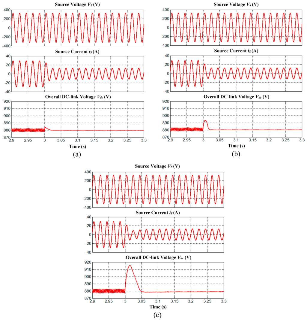
Figure 10.
Simulation results of SAPF which include source voltage (phase A), source current (phase A) and overall DC-link voltage for dynamic-state condition of capacitive to inductive load obtained using (a) the proposed algorithm with IED control; (b) the conventional algorithm with FLC and (c) PI techniques.
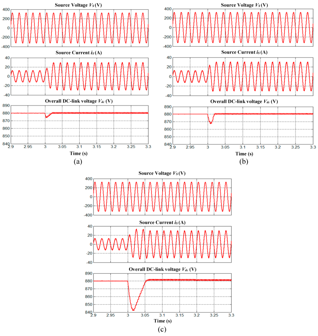
Figure 11.
Simulation results of SAPF which include source voltage (phase A), source current (phase A) and overall DC-link voltage for dynamic-state condition of inductive to resistive load obtained using (a) the proposed algorithm with IED control; (b) the conventional algorithm with FLC and (c) PI techniques.
Based on all the results obtained from simulation works, it is proven that the proposed algorithm with IED control performs outstandingly under both steady-state and dynamic-state conditions with low THD values, high accuracy, low overshoot, low undershoot, and fast response time. By utilizing the advantages of the indirect voltage error manipulation approach, the proposed algorithm gains the ability to accurately eliminate any resulting voltage error, via an alternative route without disturbing the normal operation of the regulation process. Under steady-state conditions, the resulted voltage errors appear as steady-state errors. Meanwhile, under dynamic-state conditions, the resulted voltage errors appear as overshoot and undershoot. Hence, by continuously providing an accurate IED value, the steady-state error is eliminated and the dynamic response is improved. Moreover, when the DC-link voltage of SAPF is accurately maintained at desired setpoint, injection currents can accurately be generated to cancel out the presence of current harmonics in the power system, thereby improving the mitigation performance of SAPF. On the other hand, the conventional algorithms with PI and FLC techniques perform effectively under steady-state conditions, but they are unable to track and respond fast enough to rapid changes of nonlinear loads under dynamic-state conditions. Since the conventional algorithms are designed to directly process the entire voltage error, excessive delay may be imposed to the generation of magnitude due to unnecessary computational burden and inefficient operation of PI and FLC techniques. As a result, poor dynamic performances with large overshoot, undershoot and response time are observed.
In addition, other important aspects of the three-level NPC inverter-based SAPF which include voltage balancing of splitting DC-link capacitors and neutral-point voltage deviation control are thoroughly investigated to further verify effectiveness of the proposed SAPF. Based on Figure 8 and Figure 9, it is clear that voltages across both splitting DC-link capacitors ( and ) are equally maintained as half of the overall DC-link voltage with minimal neutral-point voltage deviation and thus confirming the effectiveness neutral-point voltage deviation control algorithm applied in the proposed SAPF.
6. Experimental Verification
A laboratory prototype is developed to validate practically performance of the proposed algorithm with IED control. The experimental setup for the proposed SAPF is shown in Figure 12. For experimental testing, the supply voltage source is set at 100 Vrms, which is supplied from a programmable AC source. Meanwhile, the desired overall DC-link reference voltage is set at 220 V. Furthermore, a TMS320F28335 Digital Signal Processor (DSP) board is configured and programmed to perform all control algorithms of the SAPF and to generate the desired switching signals for the three-phase three-level NPC inverter. Similar analysis which has been performed in the simulation work is considered for experimental analysis.
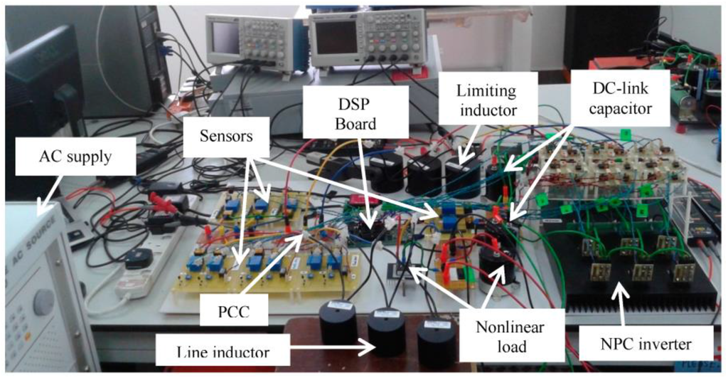
Figure 12.
Experimental setup for the proposed SAPF.
The experimental results (phase A) of SAPF utilizing the proposed algorithm with IED control which includes source voltage , load current , injection current , and source current , for capacitive, inductive and resistive loads are shown in Figure 13. Meanwhile, the resulted THD values of mitigated source current in all phases resulted from SAPF utilizing each DC-link capacitor voltage regulation algorithm are recorded in Table 7. The findings confirm that SAPF utilizing each DC-link capacitor voltage regulation algorithm has successfully removed the current harmonics generated by all nonlinear loads, resulting in THD values of below 5%. However, SAPF utilizing the proposed algorithm with IED control performs outstandingly by achieving the lowest THD values for all nonlinear loads. Moreover, the mitigated source current seems to work in phase with the source voltage and thus leading to almost unity power factor.
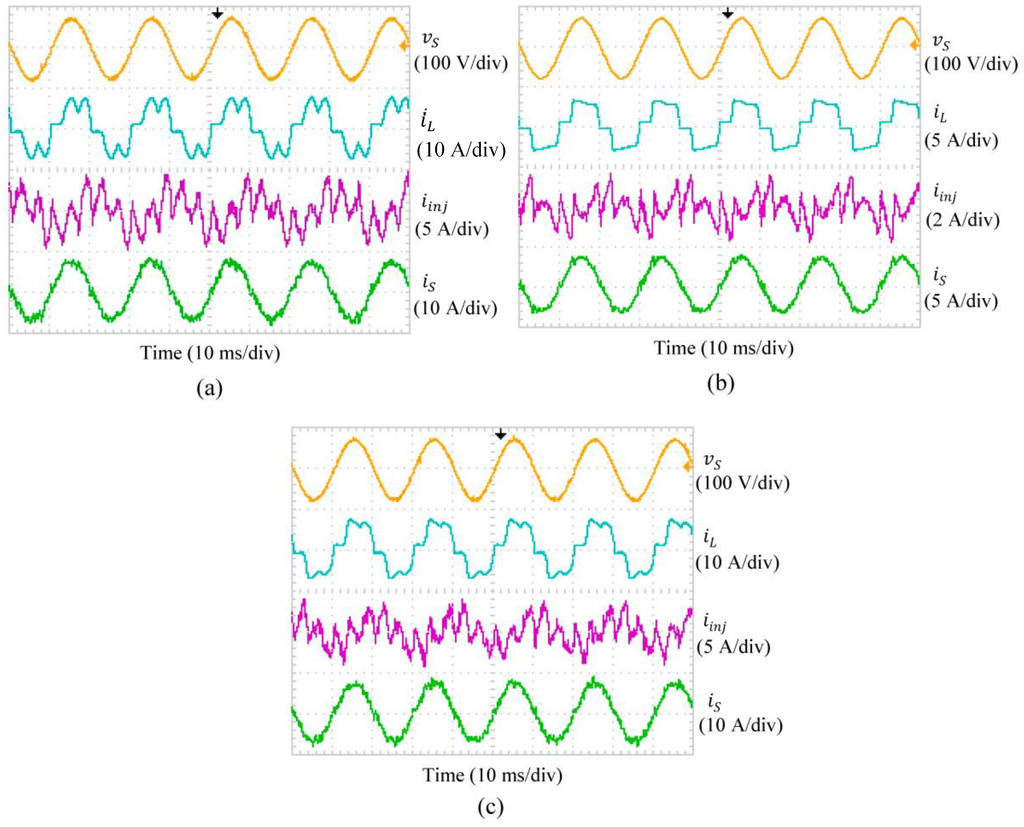
Figure 13.
Experimental results (Phase A) of SAPF utilizing the proposed algorithm with IED control which include source voltage , load current , injection current and source current for (a) capacitive; (b) inductive and (c) resistive loads.
Table 7.
THD values of source current in all phases resulted from SAPF utilizing each DC-link capacitor voltage regulation algorithm (experimental result).
On the other hand, comparative analysis in term of accuracy for each DC-link capacitor voltage regulation algorithm conducted under steady-state conditions of capacitive, inductive and resistive loads are shown in Figure 14. Meanwhile, the responses of each DC-link capacitor voltage regulation algorithm under dynamic-state conditions are shown in Figure 15. The corresponding % ACC values and dynamic performances are summarized in Table 8.
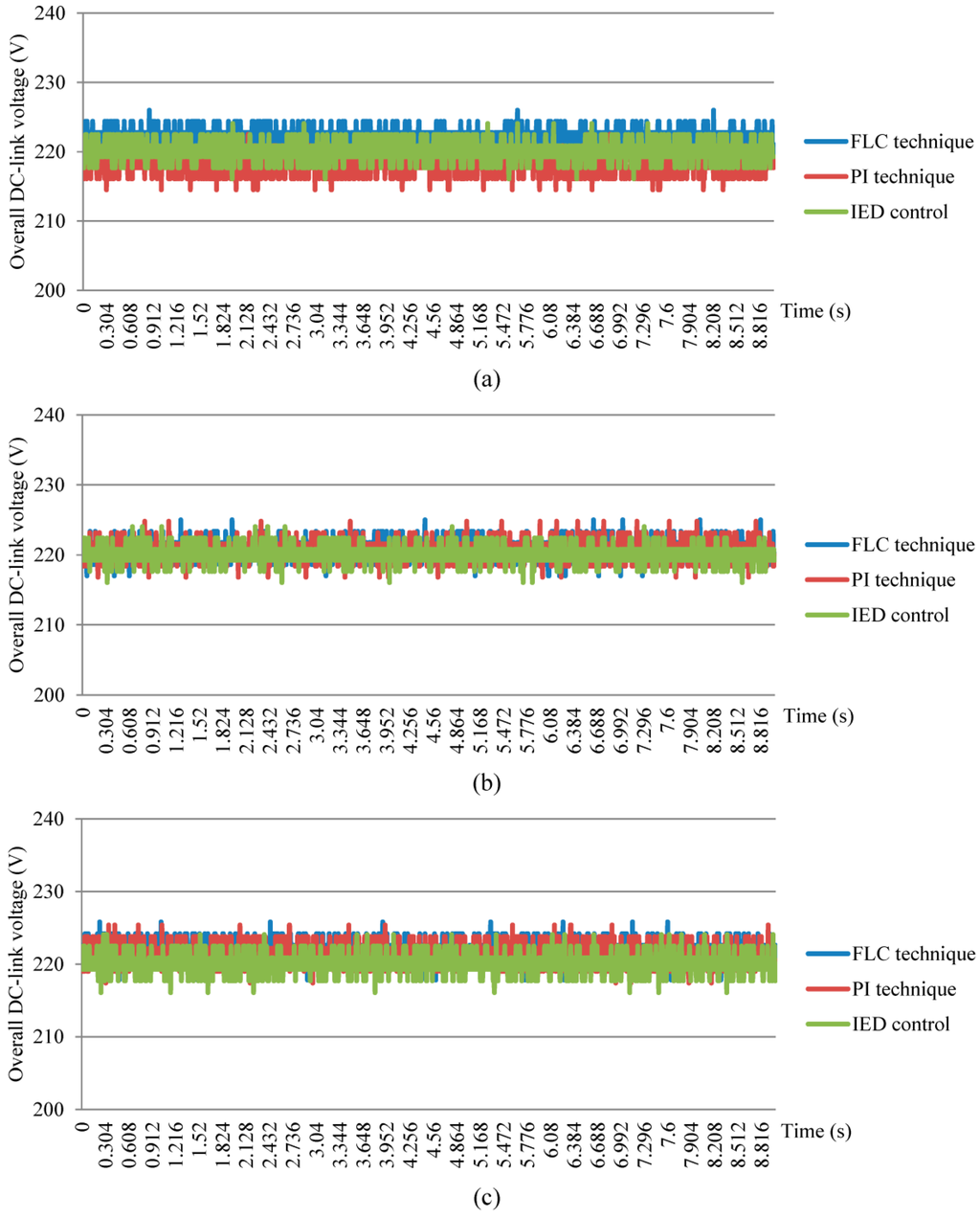
Figure 14.
Performance comparison of DC-link capacitor voltage regulation algorithms with reference voltage of 220 V for steady-state conditions of (a) capacitive; (b) inductive and (c) resistive loads.
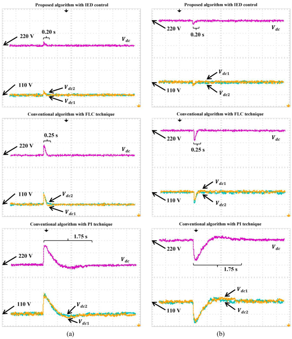
Figure 15.
Experimental results of SAPF with different DC-link capacitor voltage regulation algorithms which include overall DC-link voltage (20 V/div), and splitting DC-link capacitor voltages and (10 V/div) for dynamic-state conditions of (a) capacitive to inductive and (b) inductive to resistive loads.
Table 8.
Voltage regulation performance of each DC-link capacitor voltage regulation algorithm (experimental result).
Under steady-state conditions, it is clear that the proposed algorithm with IED control performs outstandingly by achieving the highest accuracy of 99.96%, 99.98%, and 99.96% for capacitive, inductive and resistive loads, respectively. Meanwhile, the conventional algorithm with PI technique performs poorly by producing a regulated voltage with lower accuracy of 99.31% (capacitive), 99.63% (inductive) and 99.36% (resistive). The worst performance is demonstrated by the conventional algorithm with FLC technique where the lowest accuracy of 99.09%, 99.54%, and 99.18% are recorded for capacitive, inductive and resistive loads respectively.
For dynamic-state condition of capacitive to inductive, the proposed algorithm with IED control performs outstandingly with the lowest overshoot of 6 V, no undershoot, and the fastest response time of 0.20 s. Meanwhile, the conventional algorithm with FLC technique performs poorly with overshoot of 16 V, no undershoot, and response time of 0.25 s. The worst dynamic performance is demonstrated by the conventional algorithm with PI technique which performs with largest overshoot of 32 V, undershoot of 4 V, and response time of 1.75 s. Similarly, for inductive to resistive, the best dynamic performances is demonstrated by the proposed algorithm which performs with the lowest undershoot of 6 V, no overshoot, and fastest response time of 0.20 s. Meanwhile, the conventional algorithm with PI technique shows the worst dynamic performance with the largest undershoot of 32 V, overshoot of 6 V, and response time of 1.75 s. Although the conventional algorithm with FLC technique is observed to perform better than PI technique, it still performs with significant undershoot of 16 V, and response time of 0.25 s. Furthermore, voltages across both splitting DC-link capacitors ( and ) are equally maintained as half of the overall DC-link voltage with minimal neutral-point voltage deviation (referring to Figure 15), and thus confirming effectiveness of the neutral-point voltage deviation control algorithm applied in the proposed SAPF.
Moreover, it can be observed from the analyses conducted in both simulation and experimental works, there are some discrepancies between the simulation and experimental results. It is obvious that the experimental results obtained for all control algorithms are slightly worse than the simulation results. Meanwhile, the most significant discrepancy between the simulation and experimental results is observed for the response time of the proposed algorithm with IED control and conventional algorithm with FLC technique. This is basically due to the fact that the control processes in experimental work are actually far more difficult as compared to that in simulation work. In practical reality, the control algorithms need to handle system variations resulting from dissimilar characteristic of switching devices, imbalance of DC-link capacitor due to fabrication tolerances, continuous voltage variation across the splitting DC-link capacitors, and other unexpected events that are not considered in the simulation work. Therefore, slight performance degradation and additional time delay exhibited by control algorithms are unavoidable in the experimental work. In fact, previous literature has reported on these findings [8,23,29]. Based on Table 6 and Table 8, it can be observed that additional time delays exhibited by all control algorithms in the experimental work are quite similar: proposed algorithm with IED control (0.180 s), conventional algorithm with FLC technique (0.225 s) and conventional algorithm with PI technique (0.250 s). Owing to the additional time delay, large discrepancies on response time are resulted between simulation and experimental results.
Most importantly, the experimental results obtained are in agreement with the simulation results where both simulation and experimental results have clearly proved the superiority of the proposed algorithm with IED control over the conventional algorithm with the FLC and PI techniques.
7. Conclusions
This paper has successfully demonstrated a new DC-link capacitor voltage regulation algorithm with inverted error deviation (IED) control for three-phase three-level NPC inverter-based SAPF. In this algorithm, the FLC technique is applied to systematically control the generation of IED so as to indirectly manipulate the resulting voltage error. Based on this technique, the degree of overall DC-link voltage deviation (overshoot and undershoot) is processed, and simultaneously, the most appropriate IED which contributes to reduction of overall DC-link voltage deviation is specified. In contrast to the conventional algorithms which perform by processing entirely the resulted voltage error, the proposed algorithm which performs by considering only deviations to voltage error, reduces the required computational efforts and simultaneously improves dynamic performances. Comprehensive analyses in both steady-state and dynamic-state conditions are conducted to evaluate performance of the proposed algorithm. Simulation work reveals that the proposed algorithm is able to perform with high accuracy during steady-state conditions. Moreover, utilization of the proposed algorithm has improved the mitigation performance of SAPF by achieving low THD values. On the other hand, significant improvement can be observed during dynamic-state conditions where the proposed algorithm has successfully performed with fast response time, low overshoot and low undershoot. The proposed algorithm is not limited to inverter-based SAPF with specific types of load. In fact, it is proven to work effectively under various types of nonlinear loads. Furthermore, hardware test results have confirmed effectiveness of the proposed algorithm in both steady-state and dynamic-state conditions as conducted in simulation work. Low THD values, high accuracy, low overshoot, low undershoot, and fast response time clearly show advantages of the proposed algorithm over the conventional algorithms especially in dealing with dynamic-state conditions.
Author Contributions
Yap Hoon designed and developed the main parts of the research work which includes simulation model, experimental setup, and analyses of the results obtained. Yap Hoon was also mainly responsible for manuscript preparation. Mohd Amran Mohd Radzi contributed in simulation, experimental, and manuscript preparation. Mohd Khair Hassan and Nashiren Farzilah Mailah were in charged in verifying the work and have actively contributed in finalizing the manuscript.
Conflicts of Interest
The authors declare no conflict of interest.
References
- Kale, M.; Ozdemir, E. An adaptive hysteresis band current controller for shunt active power filter. Electr. Power Syst. Res. 2005, 73, 113–119. [Google Scholar] [CrossRef]
- Dai, Y.; Dai, W. Harmonic and reactive power compensation with artificial neural network technology. In Proceedings of the 7th World Congress on Intelligent Control and Automation, Chongqing, China, 25–27 June 2008; pp. 9001–9006.
- Hoon, Y.; Radzi, M.A.M.; Hassan, M.K.; Mailah, N.F. Enhanced instantaneous power theory with average algorithm for indirect current controlled three-level inverter-based shunt active power filter under dynamic state conditions. Math. Probl. Eng. 2016, 2016, 9682512. [Google Scholar] [CrossRef]
- Akagi, H. Active harmonic filters. Proc. IEEE 2005, 93, 2128–2141. [Google Scholar] [CrossRef]
- El-Habrouk, M.; Darwish, M.K.; Mehta, P. Active power filters: A review. IEE Proc. Electr. Power Appl. 2000, 147, 403–413. [Google Scholar] [CrossRef]
- Singh, B.; Al-Haddad, K.; Chandra, A. A review of active filters for power quality improvement. IEEE Trans. Ind. Electron. 1999, 46, 960–971. [Google Scholar] [CrossRef]
- Djazia, K.; Krim, F.; Chaoui, A.; Sarra, M. Active power filtering using the zdpc method under unbalanced and distorted grid voltage conditions. Energies 2015, 8, 1584–1605. [Google Scholar] [CrossRef]
- Radzi, M.A.M.; Rahim, N.A. Neural network and bandless hysteresis approach to control switched capacitor active power filter for reduction of harmonics. IEEE Trans. Ind. Electron. 2009, 56, 1477–1484. [Google Scholar] [CrossRef]
- Kale, M.; Ozdemir, E. Harmonic and reactive power compensation with shunt active power filter under non-ideal mains voltage. Electr. Power Syst. Res. 2005, 74, 363–370. [Google Scholar] [CrossRef]
- Jain, N.; Gupta, A. Comparison between two compensation current control methods of shunt active power filter. Int. J. Eng. Res. Gen. Sci. 2014, 2, 603–615. [Google Scholar]
- Wamane, S.S.; Baviskar, J.R.; Wagh, S.R. A comparative study on compensating current generation algorithms for shunt active filter under non-linear load conditions. Int. J. Sci. Res. Publ. 2013, 3, 1–6. [Google Scholar]
- Dey, P.; Mekhilef, S. Synchronous reference frame based control technique for shunt hybrid active power filter under non-ideal voltage. In Proceedings of the IEEE Innovative Smart Grid Technologies—Asia (ISGT Asia), Kuala Lumpur, Malaysia, 2014; pp. 481–486.
- Rodríguez, J.; Lai, J.-S.; Peng, F.Z. Multilevel inverters: A survey of topologies, controls and applications. IEEE Trans. Ind. Electron. 2002, 49, 724–738. [Google Scholar] [CrossRef]
- Soto, D.; Green, T.C. A comparison of high-power converter topologies for the implementation of facts controllers. IEEE Trans. Ind. Electron. 2002, 49, 1072–1080. [Google Scholar] [CrossRef]
- Gui, S.W.; Lin, Z.J.; Huang, S.H. A varied vsvm strategy for balancing the neutral-point voltage of dc-link capacitors in three-level npc converters. Energies 2015, 8, 2032–2047. [Google Scholar] [CrossRef]
- Massoud, A.M.; Finney, S.J.; Cruden, A.J.; Williams, B.W. Three-phase, three-wire, five-level cascaded shunt active filter for power conditioning, using two different space vector modulation techniques. IEEE Trans. Ind. Electron. 2007, 22, 2349–2361. [Google Scholar] [CrossRef]
- Salim, C.; Toufik, B.M. Three-level (npc) shunt active power filter performances based on fuzzy controller for harmonic currents compensation under non-ideal voltage conditions. Int. J. Electr. Eng. Inform. 2014, 6, 342–358. [Google Scholar] [CrossRef]
- Afghoul, H.; Krim, F. Comparison between pi and fuzzy dpc control of a shunt active power filter. In Proceedings of the IEEE International Energy Conference and Exhibition (ENERGYCON), Florence, Italy, 2012; pp. 146–151.
- Suresh, Y.; Panda, A.K.; Suresh, M. Real-time implementation of adaptive fuzzy hysteresis-band current control technique for shunt active power filter. IET Power Electron. 2012, 5, 1188–1195. [Google Scholar] [CrossRef]
- Jain, S.K.; Agrawal, P.; Gupta, H.O. Fuzzy logic controlled shunt active power filter for power quality improvement. IEE Proc. Electr. Power Appl. 2002, 149, 317–328. [Google Scholar] [CrossRef]
- Karuppanan, P.; Mahapatra, K.K. Pi and fuzzy logic controllers for shunt active power filter—A report. ISA Trans. 2012, 51, 163–169. [Google Scholar] [CrossRef]
- Karuppanan, P.; Mahapatra, K.K. Pi, pid and fuzzy logic controller for reactive power and harmonic compensation. ACEEE Int. J. Electr. Power Eng. 2010, 1, 54–58. [Google Scholar]
- Zeng, F.-P.; Tan, G.-H.; Wang, J.-Z.; Ji, Y.-C. Novel single-phase five-level voltage-source inverter for the shunt active power filter. IET Power Electron. 2010, 3, 480–489. [Google Scholar] [CrossRef]
- Belaidi, R.; Haddouche, A.; Guendouz, H. Fuzzy logic controller based three-phase shunt active power filter for compensating harmonics and reactive power under unbalanced mains voltages. Energy Procedia 2012, 18, 560–570. [Google Scholar] [CrossRef]
- Mikkili, S.; Panda, A.K. Simulation and real-time implementation of shunt active filter id-iq control strategy for mitigation of harmonics with different fuzzy membership functions. IET Power Electron. 2012, 5, 1856–1872. [Google Scholar] [CrossRef]
- Mekri, F.; Mazari, B.; Machmoum, M. Control and optimization of shunt active power filter parameters by fuzzy logic. Can. J. Electr. Comput. Eng. 2006, 31, 127–134. [Google Scholar] [CrossRef]
- Gupta, U.D.; Das, P.; Hoque, M.A. A fuzzy controlled shunt active power filter for reducing current harmonics and reactive power compensation. In Proceedings of the International Conference on Electrical Engineering and Information Communication Technology (ICEEICT), Dhaka, Bangladesh, 21–23 May 2015; pp. 1–5.
- Azevedo, C.C.; Ribeiro, R.L.A.; Jacobina, C.B.; Sousa, R.M. Dc-link regulator for shunt power active filter using feed-forward control strategy. In Proceedings of the XI Brazilian Power Electronics Conference, Praiamar, Cape Verde, 11–15 September 2011; pp. 877–883.
- Zainuri, M.A.A.M.; Radzi, M.A.M.; Soh, A.C.; Mariun, N.; Rahim, N.A. Dc-link capacitor voltage control for single-phase shunt active power filter with step size error cancellation in self-charging algorithm. IET Power Electron. 2016, 9, 323–335. [Google Scholar] [CrossRef]
- Diwan, S.P.; Inamdar, H.P.; Vaidya, A.P. Simulation studies of shunt passive harmonic filters: Six pulse rectifier load power factor improvement and harmonic control. ACEEE Int. J. Electr. Power Eng. 2011, 2, 1–6. [Google Scholar]
- Marks, J.H.; Green, T.C. Predictive transient-following control of shunt and series active power filters. IEEE Trans. Power Electron. 2002, 17, 574–584. [Google Scholar] [CrossRef]
- Jain, S.K.; Agrawal, P.; Gupta, H.O. Design simulation and experimental investigations, on a shunt active power filter for harmonics, and reactive power compensation. Electr. Power Compon. Syst. 2003, 31, 671–692. [Google Scholar] [CrossRef]
- Krim, F. Parameters estimation of shunt active filter for power quality improvement. In Proceedings of the International Power Engineering and Optimization Conference (PEOCO), Shah Alam, Selangor, Malaysia, 6–7 June 2011; pp. 306–311.
- Rahman, N.A.; Radzi, M.A.M.; Mariun, N.; Soh, A.C.; Rahim, N.A. Integration of dual intelligent algorithms in shunt active power filter. In Proceedings of the IEEE Conference on Clean Energy and Technology (CEAT), Langkawi, Malaysia, 18–20 November 2013; pp. 259–264.
- Khadem, S.K.; Basu, M.; Conlon, M.F. Harmonic power compensation capacity of shunt active power filter and its relationship with design parameters. IET Power Electron. 2014, 7, 418–430. [Google Scholar] [CrossRef]
- Yao, J.; Green, T. Dc-link capacitors sizing for three-level neutral-point-clamped inverters in four-wire distributed generation systems. In Proceedings of the International Conference on Future Power Systems, Amsterdam, The Netherlands, 16–18 November 2005; pp. 1–5.
- Pou, J.; Pindado, R.; Boroyevich, D. Evaluation of the low-frequency neutral-point voltage oscillations in the three-level inverter. IEEE Trans. Ind. Electron. 2005, 52, 1582–1588. [Google Scholar] [CrossRef]
- Orfanoudakis, G.I.; Yuratich, M.A.; Sharkh, S.M. Analysis of dc-link capacitor current in three-level neutral point clamped and cascaded h-bridge inverters. IET Power Electron. 2013, 6, 1376–1389. [Google Scholar] [CrossRef]
- Ponnaluri, S.; Brickwedde, A. Generalized system design of active filters. In Proceedings of the Power Electronics Specialists Conference (PESC), Vancouver, BC, Canada, 17–22 June 2001; pp. 1414–1419.
- Ng, C.H.; Busawon, K.; Putrus, G.A.; Ran, L. Fast-individual-harmonic-extraction technique. IEE Proc. Gener. Transm. Distrib. 2005, 152, 556–562. [Google Scholar] [CrossRef]
- Bhalodi, K.H.; Agarwal, P. Space vector modulation with dc-link voltage balancing control for three-level inverters. ACEEE Int. J. Commun. 2010, 1, 14–18. [Google Scholar]
- Lee, Y.-H.; Suh, B.-S.; Hyun, D.-S. A novel pwm scheme for a three-level voltage source inverter with gto thyristors. IEEE Trans. Ind. Appl. 1996, 32, 260–268. [Google Scholar]
- Zhou, D.; Rouaud, D.G. Experimental comparisons of space vector neutral point balancing strategies for three-level topology. IEEE Trans. Power Electron. 2001, 16, 872–879. [Google Scholar] [CrossRef]
- Gupta, A.K.; Khambadkone, A.M. A space vector pwm scheme for multilevel inverters based on two-level space vector pwm. IEEE Trans. Ind. Electron. 2006, 53, 1631–1639. [Google Scholar] [CrossRef]
- Hu, H.; Yao, W.; Lu, Z. Design and implementation of three-level space vector pwm ip core for fpgas. IEEE Trans. Ind. Electron. 2007, 22, 2234–2244. [Google Scholar] [CrossRef]
- Green, T.C.; Marks, J.H. Control techniques for active power filters. IEE Proc. Electr. Power Appl. 2005, 152, 369–381. [Google Scholar] [CrossRef]
- Mikkili, S.; Panda, A.K. Types-1 and -2 fuzzy logic controllers-based shunt active filter id-iq control strategy with different fuzzy membership functions for power quality improvement using rtds hardware. IET Power Electron. 2013, 6, 818–833. [Google Scholar] [CrossRef]
- Wu, Y.; Zhang, B.; Lu, J.; Du, K.-L. Fuzzy logic and neuro-fuzzy systems: A systematic introduction. Int. J. Artif. Intell. Expert Syst. 2011, 2, 47–80. [Google Scholar]
- Naaz, S.; Alam, A.; Biswas, R. Effect of different defuzzification methods in a fuzzy based load balancing application. Int. J. Comput. Sci. Issues 2011, 8, 261–267. [Google Scholar]
- Teke, A.; Bayindir, K.; Tumay, M. Fast sag/swell detection method for fuzzy logic controlled dynamic voltage restorer. IET Gener. Transm. Distrib. 2010, 4, 1–12. [Google Scholar] [CrossRef]
- Soo, Y.Y.; Myung, J.C. Stability analysis of a fuzzy logic controller for an uncertain dynamic system. In Proceedings of the Third IEEE Conference on Fuzzy Systems, Orlando, FL, USA, 26–29 June 1994; pp. 1028–1034.
- IEEE Standard 519, IEEE Recommended Practice and Requirement for Harmonic Control in Electric Power Systems; IEEE Power and Energy Society: New York, NY, USA, 2014.
© 2016 by the authors; licensee MDPI, Basel, Switzerland. This article is an open access article distributed under the terms and conditions of the Creative Commons Attribution (CC-BY) license (http://creativecommons.org/licenses/by/4.0/).