Article

Application of Renewable Energies: Effects of Oxyhydrogen Negative Pressure Indraft on Combustion and Emission of Biobutanol/Gasoline Combined Supply Engine Under Exhaust Gas Recirculation Coupled Lean–Burn

1
National Key Laboratory of Automotive Chassis Integration and Bionics, Jilin University, Changchun 130022, China
2
College of Automotive Engineering, Jilin University, Changchun 130022, China
*
Author to whom correspondence should be addressed.
Energies 2026, 19(6), 1544; https://doi.org/10.3390/en19061544
Submission received: 17 February 2026 / Revised: 16 March 2026 / Accepted: 18 March 2026 / Published: 20 March 2026
(This article belongs to the Special Issue Advances in Carbon-Neutral Fuel High-Efficiency Clean Combustion)

Abstract

Combining biobutanol and oxyhydrogen in an SI engine can reduce fossil-fuel use and improve power, but oxyhydrogen increases NOx. Without sacrificing combustion stability, this work investigates lean–burn coupled with exhaust gas recirculation for a gasoline port injection + biobutanol direct injection + oxyhydrogen in-cylinder negative pressure indraft engine, across five oxyhydrogen flow levels, four exhaust gas recirculation ratios, and three excess air ratios. Results show that with lean–burn + exhaust gas recirculation, oxyhydrogen more effectively lowers the coefficient of variation of indicated mean effective pressure and increases indicated mean effective pressure, peak cylinder pressure, and peak heat release rate. With 16 L/min oxyhydrogen, the negative effects of 6–12% exhaust gas recirculation on CA 0–10 and CA 10–90 are mitigated for all excess air ratios, and the crank angle corresponding to peak pressure remains optimal under lean conditions when 6% ≤ exhaust gas recirculation ≤ 12%. Oxyhydrogen reduces CO and HC after exhaust gas recirculation, while lean–burn dominates CO reduction. Exhaust gas recirculation suppresses NO more than lean–burn. At 1.1 ≤ excess air ratios ≤ 1.2, the optimal exhaust gas recirculation is 12%, ensuring favorable in-cylinder conditions. Overall, lean–burn + exhaust gas recirculation effectively controls NO and maximizes thermal efficiency and renewable-fuel substitution. The optimal strategy is “oxyhydrogen = 16 L/min, exhaust gas recirculation = 12%, 1.1 ≤ excess air ratios ≤ 1.2”.

1. Introduction

Although the large-scale development and utilization of fossil fuels have long supported industrial development and energy supply, their combustion process emits a large amount of carbon dioxide, nitrogen oxides (NOx), and particulate matter, which has had a serious impact on global climate change and the atmospheric environment. The electrification of transportation and the development of low-carbon alternative fuels for internal combustion engines have become two core solutions, among which researchers have extensively conducted research on new clean fuels that can replace traditional fossil fuels [1]. In the process of relevant research, due to the individual advantages, numerous alternative fuels have caught researchers’ attention, such as ammonia [2], ethanol [3,4,5], biobutanol [6,7], biodiesel [8], hydrogen [9,10,11], etc. Considering the processing technology and manufacturing cost of renewable energy, most scholars believe that alcohol fuel is one of the alternative fuels with the most mature processing technology and the lowest manufacturing cost. The properties of biobutanol in alcohol fuel are the most similar to those of gasoline. Biobutanol is less corrosive than other alcoholic fuels. Therefore, the blending combustion of biobutanol in gasoline engines is considered to be a new hot spot of current research.

1.1. Biobutanol

The application of biobutanol in engines is widely and deeply studied; many papers show that blending the appropriate amount of biobutanol can enhance the performance of spark ignition (SI) engines. Due to the fast combustion rate and high oxygen content of biobutanol, it can shorten the combustion stage, improve power performance, and improve the stability of engine operation [12,13,14]. In terms of engine emissions, due to the positive influence of biobutanol on mixture combustion, blending biobutanol can effectually reduce carbon monoxide (CO), hydrocarbon (HC), and NOx emission [15,16,17]. Moreover, Yu et al. [18] explore the relationship between engine particle emissions and mixed biobutanol. The data in the paper suggest that the direct injection of biobutanol has a great influence on improving the accumulation mode particles. When excess air coefficient (λ) = 0.9, adding 20% biobutanol can reduce the accumulation mode particles by 52%. However, the experiment also found that the addition of biobutanol may lead to an increase in the number of nucleation mode particles. However, there are still some restrictions in the further utilization of biobutanol in engines. When too much biobutanol is added to the mixture, the cooling effect on the cylinder temperature increases, the evaporation process of the biobutanol deteriorates, the combustion process is impeded, the power of the engine is reduced, and the fuel consumption is increased [19]. Şahin et al. [20] conducts more detailed research on a gasoline engine. During the experiment, they configured three biobutanol gasoline mixed fuel fuels (2.5% n-biobutanol, 5% n-biobutanol, 7.5% n-biobutanol) according to the volume ratio of biobutanol. The experimental results show that 2.5% biobutanol can improve in-cylinder combustion, and decrease the fuel consumption and HC emission at low loads. However, as the proportion of biobutanol continued to increase, the improvement of biobutanol on engine performance was weakened. Through comparative analysis among various experimental groups, they ultimately attributed this phenomenon to the disruption of the combustion environment caused by the excessive latent heat of vaporization exhibited by biobutanol.

1.2. Oxyhydrogen

As hydrogen has the advantages of efficient combustion and being pollution free, it is considered by many scholars to be the main development direction of energy in the future, and many experimental studies have been carried out on the combustion of hydrogen in engines. The data in the paper suggest that hydrogen can enhance the dynamics of engines and significantly reduce the CO and HC emission of engines [21,22,23,24,25]. However, the utilization of hydrogen in engines remains limited due to challenges associated with storage and transportation. As a burgeoning hydrogen energy source, oxyhydrogen possesses not only the commendable combustion properties of hydrogen but also eliminates the need for storage during production and utilization Therefore, oxyhydrogen has become a research hotspot recently. Oxyhydrogen is a combustible mixture of hydrogen and oxygen, produced through electrolysis using an alkaline aqueous solution as the raw material in a specialized hydrolysis unit. In this process, the molar ratio of hydrogen to oxygen is maintained at 2:1. Additionally, it encompasses a minor quantity of active functional groups such as hydroxyl [26,27,28,29]. Zhao et al. [30] compared the performance of engines under two fuel supply modes. The data in the paper suggest that the introduction of oxyhydrogen in both modes can shorten the crank angle (CA) 0–90 and increase the peak in-cylinder pressure (Pmax) of the engine. In addition, the utilization of oxyhydrogen can enhance the stability of combustion significantly. Other researchers also found through experiments that the utilization of oxyhydrogen can improve the experimental engine thermal efficiency and decrease fuel consumption; that is to say, oxyhydrogen produces a great positive impact on improving engine economy [31,32,33]. Salek et al. [34] innovatively used oxyhydrogen to deal with excessive CO emission during engine idle. In the experiment, they introduced 0.126 L/min oxyhydrogen when the engine is idling. The experimental results showed that CO emission dropped sharply from 2303 ppm to 52 ppm, reducing it by 98%. It can be seen that oxyhydrogen has a significant influence on improving CO emission at idling. Aside from this, there is also a lot of research about engine emission during normal engine operation. The researchers found that oxyhydrogen has a faster flame velocity and wider combustion limit, which can break the bonds of fuel molecules more quickly, promote more complete combustion reaction, and thus effectually improve CO and HC emissions [35,36,37,38]. However, due to the combustion improvements by oxyhydrogen, the in-cylinder combustion temperature will be increased, and the NOx emission will be increased [39,40]. Therefore, solving the high nitric oxide (NO) emission becomes a key problem for better application of oxyhydrogen.

1.3. Lean–Burn

Lean–burn technology is an important measure to fundamentally enhance the thermal efficiency of gasoline engines and achieve low carbonization, especially in GDI engines. The key to lean–burn lies in the reduction of in-cylinder combustion temperature, thereby reducing the heat transfer loss, enhancing the thermal efficiency, and improving the engine emission level [41]. However, researchers also found that the application of lean–burn requires a more precise and flexible control policy of spray and air flow; regardless, the injection strategy of the whole fuel supply system has a significant influence on the engine performance [42]. Quader et al. [43,44,45] conducted a detailed study on the influence of air movement on the in-cylinder combustion state during lean–burn. They found that the main factors affecting the mixture stratification were the air movement form and fuel injection timing, and the vortex has a positive influence on promoting the stratification of the in-cylinder mixture. At present, lean–burn technology still has some drawbacks. When the mixture is excessively diluted, it becomes arduous for the spark plug to consistently initiate ignition and for the flame to rapidly propagate across other regions. Therefore, the duration of the combustion will be extended accordingly, and the stability of engine operation will also be damaged. In order to solve this problem, the introduction of other auxiliary fuels has become a research direction, such as hydrogen [46,47]. Yu et al. [48,49,50] experimentally investigated the combustion characteristics of a direct injection hydrogen engine under various equivalence ratios. It has been observed that the addition of hydrogen exhibits a remarkable potential in augmenting the stable initiation of flame kernels under varying λ. Furthermore, this augmentation facilitates the combustion process and significantly enhances the coefficient of variation (CoV) pertaining to engine performance.

1.4. Exhaust Gas Recirculation (EGR)

EGR technology refers to the process of reintroducing a portion of the exhaust gas emitted from the cylinder back into the intake pipe, thereby combining it with fresh air during the air exchange phase of an internal combustion engine. EGR can increase the overall heat capacity, adjust the composition of the mixture, thereby reducing the maximum combustion temperature and NOx emission, but also deteriorating the combustion environment. As the EGR ratio increases, the flame velocity decreases, the possibility of misfire is greatly increased, thus reducing engine operation stability [51,52,53]. Bogarra et al. [54] conducted a series of experimental studies on the relationship between EGR and particulate emissions from gasoline direct injection engines. The papers prove that after the input of exhaust gas, the distribution of particulate emission from gasoline engines has changed, and the number of particles has changed from the nuclear membrane state to the aggregation state. Additionally, results also indicate that the appropriate EGR ratio can improve the engine economy, but the power performance is reduced, and the engine torque is reduced. Therefore, in order to give full play to the positive effect of EGR on the engine, other methods are needed to improve the in-cylinder combustion environment after the introduction of exhaust gas.
Because oxyhydrogen has excellent physicochemical properties, it can significantly improve combustion, thus improving the performance of gasoline engine after blending biobutanol. Yet there is little research on the impact of oxyhydrogen on the performance of engines using mixed alcohol fuel. In this research, the working relationship between oxyhydrogen and alcohol fuels is studied in detail, which makes up the blank in this field, and this paper creatively proposes a basic working mode of engines, that is, gasoline port injection + biobutanol direct injection + oxyhydrogen in-cylinder negative pressure indraft (GPI + BDI + ONPI). In order to further reduce high NOx emissions after blending oxyhydrogen, this paper will use EGR technology to inhibit the generation of NOx. Moreover, the incorporation of oxyhydrogen can effectively counterbalance the adverse impact of EGR on engine performance, optimize combustion environment after use of EGR, and enhance engine operational stability. Therefore, oxyhydrogen and EGR have a good cooperative relationship. To systematically verify the above synergistic mechanism and explore the optimal control strategy of the proposed engine mode, this paper establishes a dedicated spark–ignition engine test bench equipped with a ternary fuel composite supply system, EGR system, and dSPACE-based rapid prototype control platform, and carries out a full set of controlled bench tests. At the same time, in order to further mitigate engine emissions, this paper will deeply explore the potential of coupling oxyhydrogen with exhaust gas to enhance the performance of the EGR + BDI + ONPI + GPI engine. Therefore, the results of this study not only elucidate the synergistic mechanism of oxyhydrogen, λ, and EGR in optimizing engine combustion and reducing emissions. Moreover, it provides a feasible technical route and theoretical support for the efficient, clean, and stable operation of biobutanol–gasoline hybrid engines. The proposed engine configuration and control strategy can effectively promote the practical application of renewable alcohol fuels and reduce dependence on fossil fuels.

2. Experimental Setup and Methodology

2.1. Experimental Equipment

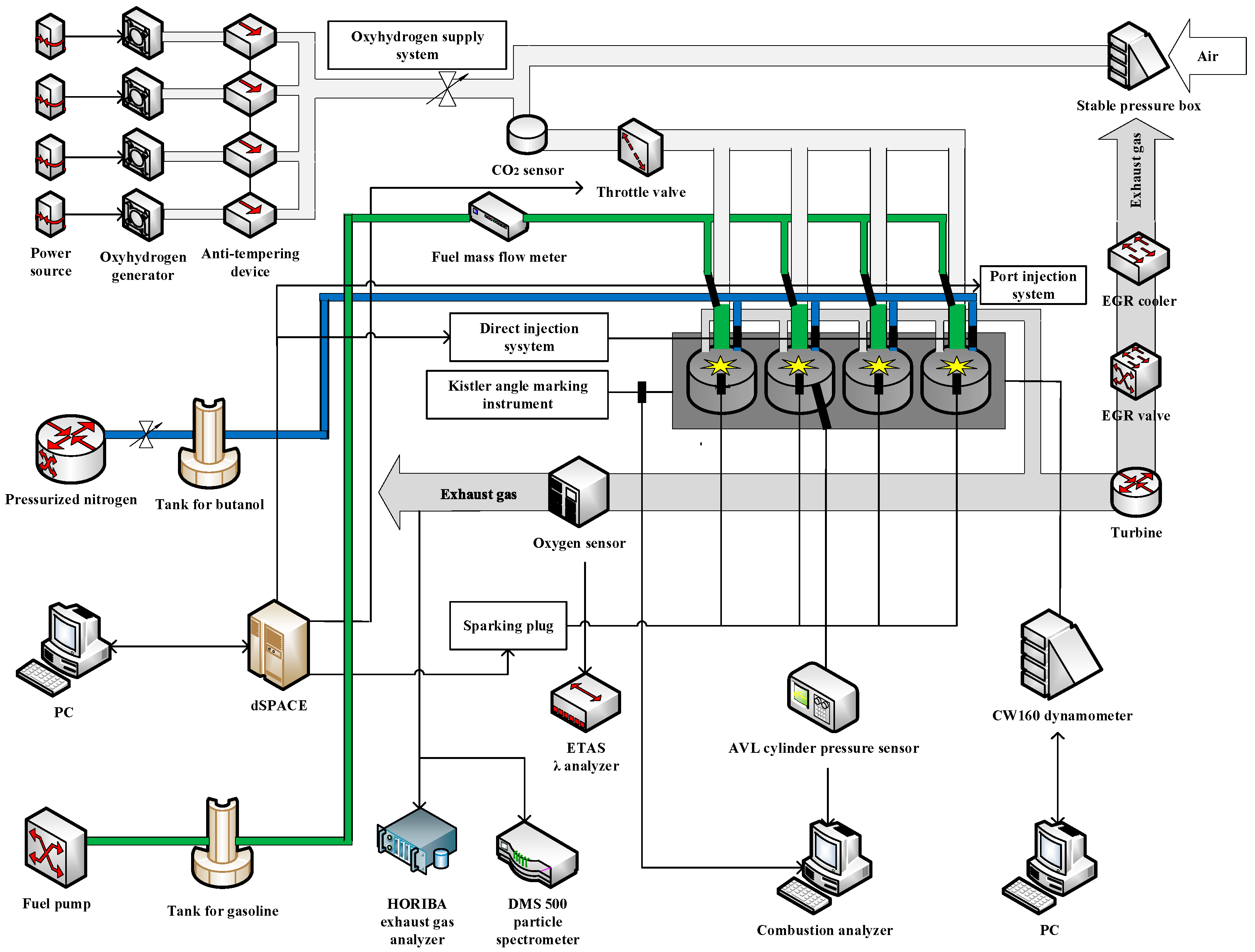
The purpose of this study is to conduct experimental research on the impact of oxyhydrogen on a four-cylinder gasoline engine, aiming to further investigate its influence. The schematic diagram illustrating the experimental set-up arrangement in this study is presented in Figure 1. The detailed data parameters of the experimental engine are presented in Table 1. This experimental engine has a composite injection system; biobutanol is injected through the in-cylinder direct injection nozzle, and gasoline is injected through the low-pressure nozzle in the inlet. In addition, we also upgraded the intake system by installing the self-built oxyhydrogen supply system and external low-pressure EGR system into the original intake system, so that oxyhydrogen and exhaust gas can enter the cylinder through the intake manifold and participate in combustion. To maintain the volumetric efficiency nearly unchanged, the throttle opening was appropriately increased when EGR was introduced. The whole oxyhydrogen supply system is mainly composed of four parts. The first part is the power supply, which provides electricity to the oxyhydrogen generator. The second part is PC, which transmits signals to the oxyhydrogen generator through radio, controlling the opening and closing of the oxyhydrogen generator and oxyhydrogen negative pressure indraft volume (ONPIv). The third part is the oxyhydrogen generator. After the oxyhydrogen generator is energized, the internal electrochemical reaction occurs, and the oxyhydrogen is produced. The fourth part is the anti-tempering device. The anti-tempering device is utilized to safeguard the oxyhydrogen generator against reverse flame propagation.
The experimental apparatus specifications are detailed in Table 2. The CW160 eddy current dynamometer (CAMA (Luoyang) Electromechanic Co., Ltd., Luoyang, China) served as the core loading unit, providing precise control over the engine while recording speed and torque values. To facilitate a comprehensive investigation into fuel blending processes and combustion effects within the cylinder, a DEWEsoft combustion analyzer is employed in this research. This apparatus enables collection and calculation of combustion data within the engine while displaying analysis results on a connected control computer. Furthermore, for exhaust emission measurements in this study, a HORIBA-MEXA584L exhaust gas analyzer is adopted due to its accurate determination capabilities for CO, HC, and NO content in exhaust gases.

2.2. Experimental Procedure

The focus of this study lies in examining the engine’s operational state within an urban environment, so the engine speed and load are respectively selected as 1500 rpm and 42 kPa. The variables in the experimental research include EGR ratio, ONPIv, and λ. The details of the test scheme are shown in Table 3. We determine the optimum injection strategy of biobutanol and gasoline through many experiments. The injection pressures of GPI and BDI are set to 0.5 MPa and 9 MPa, respectively. Additionally, the injection timing for GPI and BDI is adjusted to 340° CA before compression top dead center (BTDC) and 300° CA BTDC, correspondingly. The spark timing is kept constant throughout all test conditions to ensure comparability.
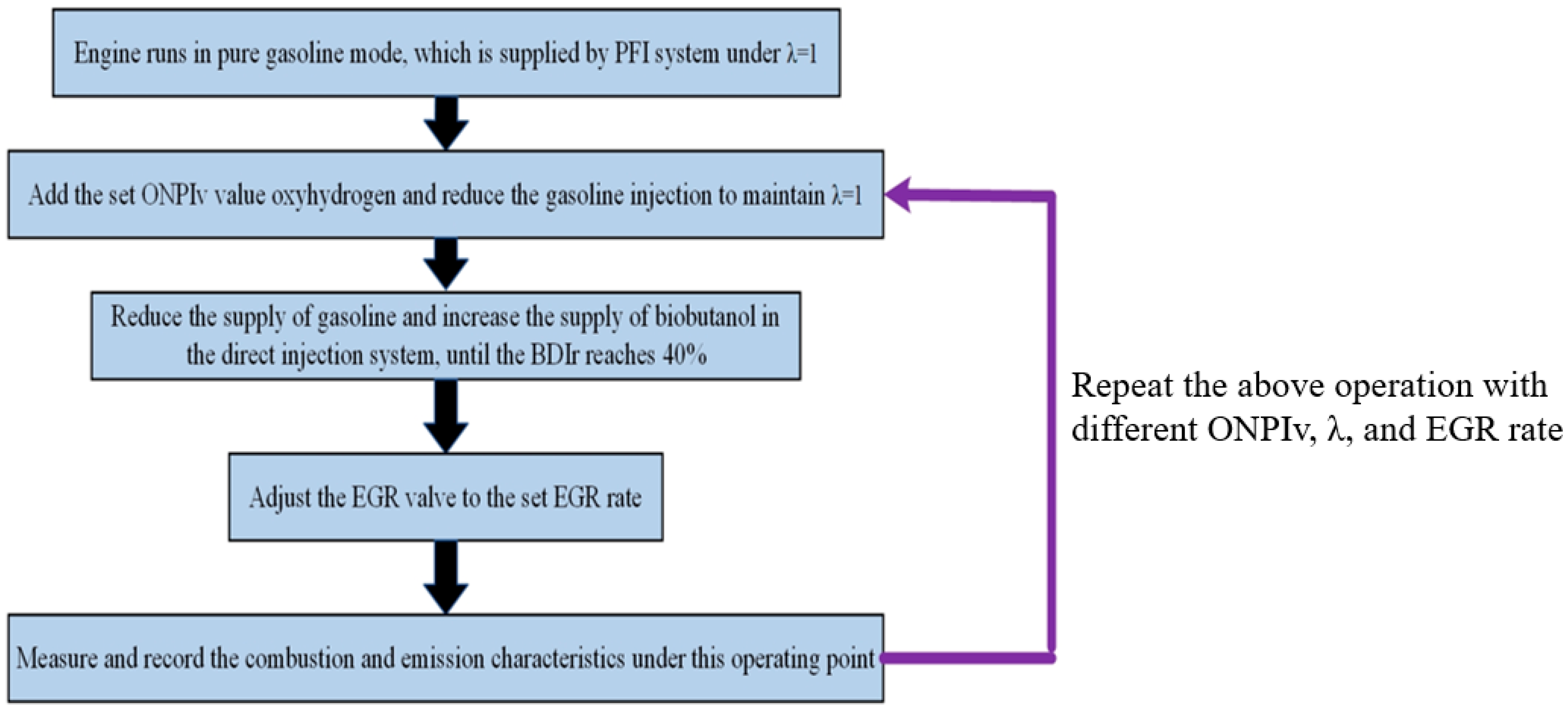
First, preheat the engine and run it in gasoline-only mode, with gasoline supplied by the PFI system. When the engine runs stably, at a certain λ, the oxyhydrogen required by the research is introduced and the gasoline supply is reduced to maintain λ unchanged. When steady-state operation was established, gasoline was progressively substituted with biobutanol in the direct injection system until the target biobutanol direct injection ratio (BDIr) of 40% was achieved. The BDIr in this article was defined as the percentage of intake air consumed by direct injection of biobutanol in the cylinder, which is the remaining effective intake air after deducting the ONPI intake air from the total intake air. In the process, λ remains unchanged. The BDIr was consistently maintained at 40% throughout the study. Figure 2 shows the specific experimental flow.

2.3. Definition of Correlated Parameters

BDIr is calculated using the following formula:
B D I r = H b i o b u t a n o l H b i o b u t a n o l + H g a s o l i n e + H o x y h y d r o g e n
where Hbiobutanol and Hgasoline represens the heat generated by biobutanol and gasoline, respectively.
Hoxyhydrogen refers to the heat generated by oxyhydrogen. However, the energy contribution of Hoxyhydrogen is negligible, so it can be ignored. The stability of engine operation is evaluated by CoV, which is defined as follows:
C o V x = σ x x ¯ × 100 %
where
x ¯ = i = 1 N x i N
σ x = i = 1 N ( x i x ¯ ) 2 N
where N is 200, and x means the indicated mean effective pressure (IMEP).
The definition formula of EGR ratio is as follows:
E G R   r a t i o = Q c o 2 · i n Q c o 2 · a i r Q c o 2 · o u t Q c o 2 · a i r × 100 %
where QCO2·in represents the volume fraction of CO2 in the air inlet port after EGR blending. QCO2·out and QCO2·air represent the volume fraction of CO2 in exhaust gas and atmosphere, respectively.

3. Results

3.1. Cylinder Pressure and Heat Release Rate (HRR)

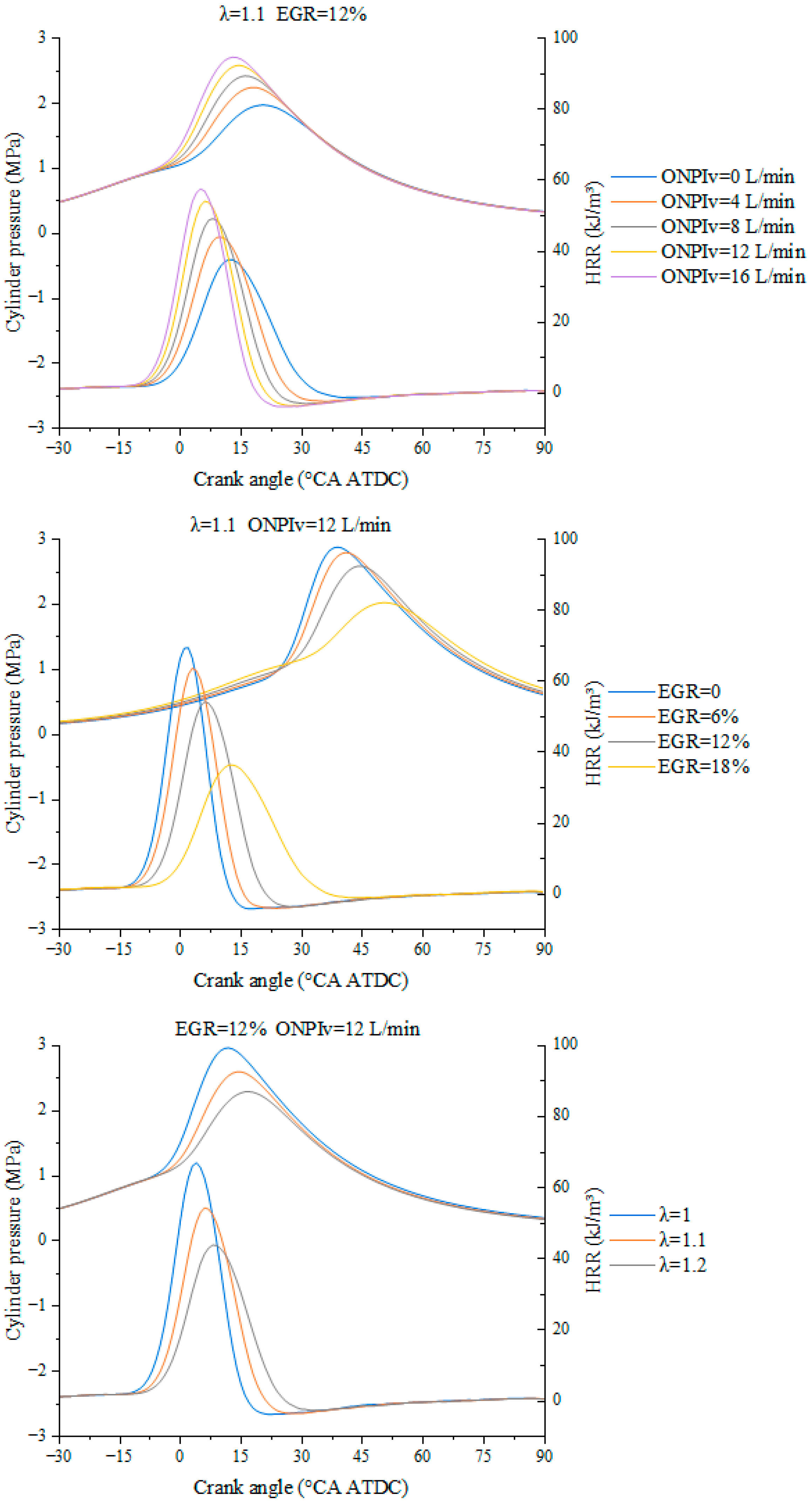
Figure 3 shows the effects of ONPIv, EGR, and λ on cylinder pressure and HRR. Under the fixed operating conditions of λ = 1.1 and EGR = 12%, as the ONPI injection flow rate increases from 0 L/min to 16 L/min, the peak pressure and peak heat release rate in the cylinder show a significant monotonic upward trend, and the combustion phase continues to advance. The active fuel injected into the intake increases the reactivity and combustible component concentration of the cylinder mixture, bringing the main combustion stage closer to the compression top dead center. More chemical energy is released in the efficient thermal power conversion zone near the top dead center, ultimately resulting in a synchronous increase in peak cylinder pressure and HRR.
Under the fixed operating conditions of λ = 1.1 and ONPIv = 12 L/min, the EGR rate is the most significant control parameter for suppressing the combustion process. As the EGR rate increases from 0 to 18%, the peak pressure and peak heat release rate in the cylinder decrease significantly, and the combustion phase is significantly delayed. The introduction of EGR reduces the oxygen concentration and fuel molecule equivalence ratio of the cylinder mixture, slowing down the flame propagation speed. Secondly, the large amount of inert components introduced by EGR, with its high heat capacity, significantly reduces the combustion temperature inside the cylinder, suppresses the combustion reaction rate, and leads to a significant delay in the combustion phase.
Under the fixed operating conditions of EGR = 12% and ONPIv = 12 L/min, as the λ increases from 1 to 1.2, the peak pressure and peak heat release rate in the cylinder show a monotonic downward trend, and the combustion phase gradually delays. When λ = 1 (theoretical air-fuel ratio), the peak pressure in the cylinder is the highest. As λ increases, the slope of the heat release rate curve decreases, and the heat release rate during the premixed combustion stage slows down. The increase in λ gradually dilutes the mixture, reduces the equivalent concentration of fuel molecules in the cylinder, decreases the reactivity of the combustible mixture, slows down the flame propagation speed, resulting in slightly prolonged ignition delay and delayed combustion phase. At the same time, the adiabatic combustion temperature of the lean mixture decreases, further suppressing the combustion reaction rate, ultimately resulting in a decrease in cylinder pressure and HRR.

3.2. Ignition Delay Period and Rapid Combustion Period (CA 0–10 and CA 10–90)

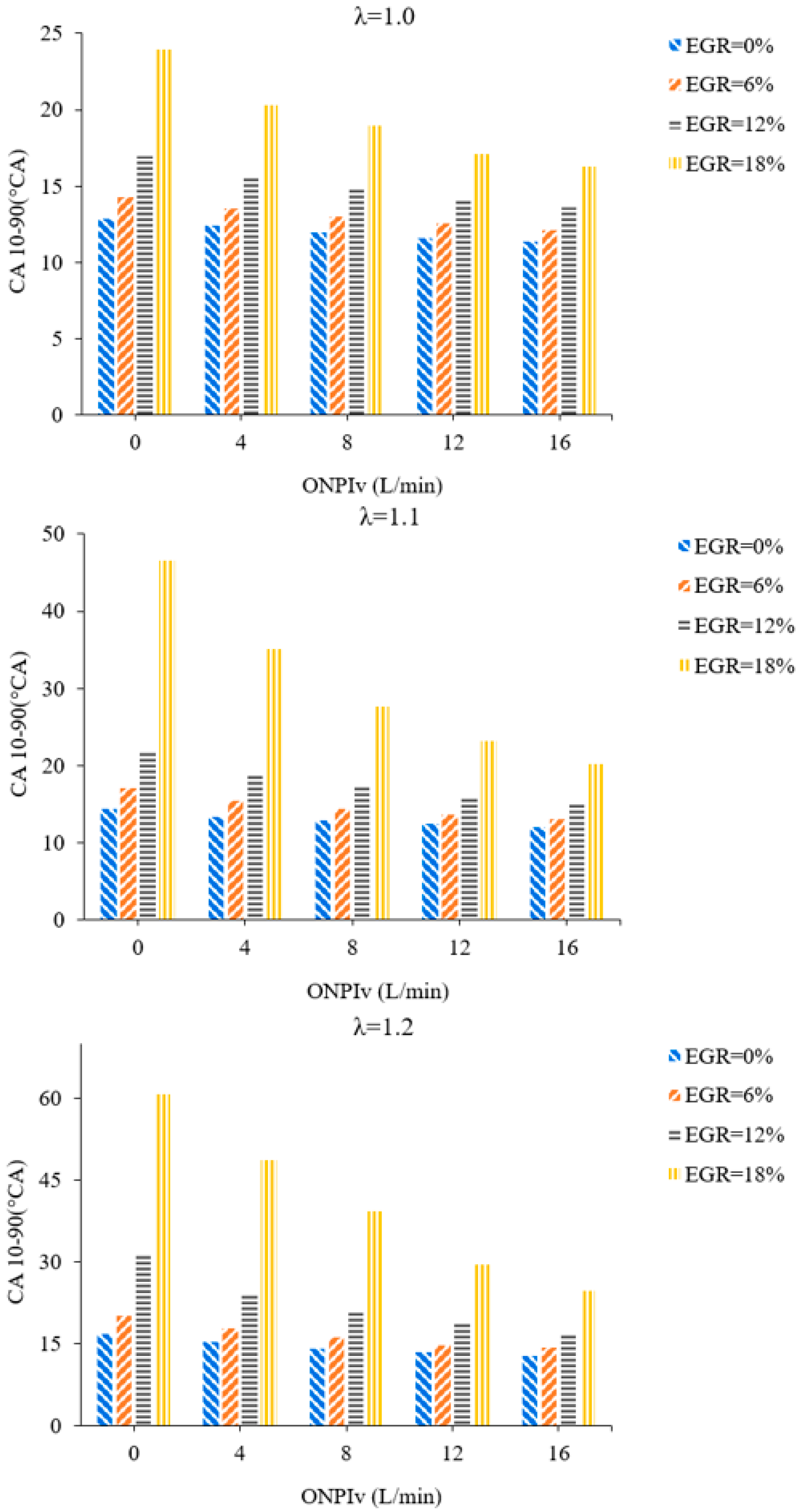
Figure 4 illustrates the change rules of CA 0–10 and CA 10–90 with ONPIv under various EGR ratios and λ. As EGR ratio increases, CA 0–10 and CA 10–90 both extend. This can be attributed to the fact that the increasing exhaust gas hinders the initiation of the flame kernel, worsens combustion environment, decreases the flame velocity, and thus extends combustion time. Meanwhile, the sensitivity of the engine without oxyhydrogen to EGR is various under various λ conditions. At λ = 1.0, 1.1, only when the EGR ratio exceeds 12%, the CA 10–90 and CA 0–10 of the original engine extend sharply. However, at λ = 1.2, when the EGR ratio exceeds 6%, the CA 10–90 and CA 0–10 prolong significantly. This is attributed to the antagonism between the positive effects of BDI and the negatory effects of EGR. The promoting influence of BDI on combustion weakens the hindering influence of EGR to a certain extent, thus improving the BDI + GPI + EGR engine’s tolerance to EGR. Nevertheless, when λ rises to 1.2, the mixture is extremely diluted and the serious deterioration of the combustion atmosphere inhibits the promotion of biobutanol on combustion. At this time, the BDI + GPI + EGR engine’s tolerance to EGR will be reduced if the resistance of EGR to combustion cannot be effectually alleviated. However, the incorporation of oxyhydrogen can be regarded as an effective approach to improve combustion characteristics of the BDI + GPI + EGR engine after blending exhaust gas, especially under a high EGR ratio.
The augmentation of λ causes a reduction in the thickness of the mixture, resulting in a decrease in both combustion temperature and the rate of chemical reaction. On the contrary, under lean–burn conditions, as ONPIv increases, CA 0–10 and CA 10–90 continuously decrease, and the larger the λ, the more obvious the trend. This suggests that the involvement of oxyhydrogen as a supplementary fuel in combustion plays a crucial role in enhancing the combustion atmosphere. In addition, when λ = 1.0, 1.1, 1.2 and EGR = 6%, 12 L/min, oxyhydrogen shortens CA 0–90 to the level below BDI + GPI mode (EGR = 0%, ONPIv = 0 L/min). The excellent combustion characteristics of oxyhydrogen, such as enhanced flame velocity and reduced ignition energy, contribute to the optimization of in-cylinder combustion atmosphere when exhaust gas participates in the process. This facilitates the ignition of flame kernel and enhances the subsequent flame propagation process, ultimately resulting in a reduced CA 0–90 duration. However, with continue augmentation of the EGR ratio, more oxyhydrogen is needed to improve the combustion. When the EGR is set to 12%, the intervention of 16 L/min oxyhydrogen is required to obtain a similar improved combustion effect. Meanwhile, when EGR ratio is increased to 18%, the CA 0–10 and CA 10–90 after blending 16 L/min oxyhydrogen are still slightly longer than the original engine (EGR = 0%, ONPIv = 0 L/min, λ = 1.0). This can be attributed to the fact that the negatory influence of an 18% EGR ratio on the propagation and development of flame is stronger than the positive effect of blending 16 L/min oxyhydrogen. In conclusion, in order to maximize the positive role of EGR and ensure the rapid flame development and propagation, the control policy of “λ < 1.2 + EGR ≤ 12% + ONPIv = 16 L/min” is the optimum cooperation of the EGR + BDI + ONPI + GPI engine as for CA 0–10. The control policy of “λ < 1.2 + EGR ≤ 6% + ONPIv = 16 L/min” is the optimum cooperation of EGR + BDI + ONPI + GPI engine as for CA 10–90.

3.3. Pmax and Crank Angle Corresponding to Pmax (APmax)

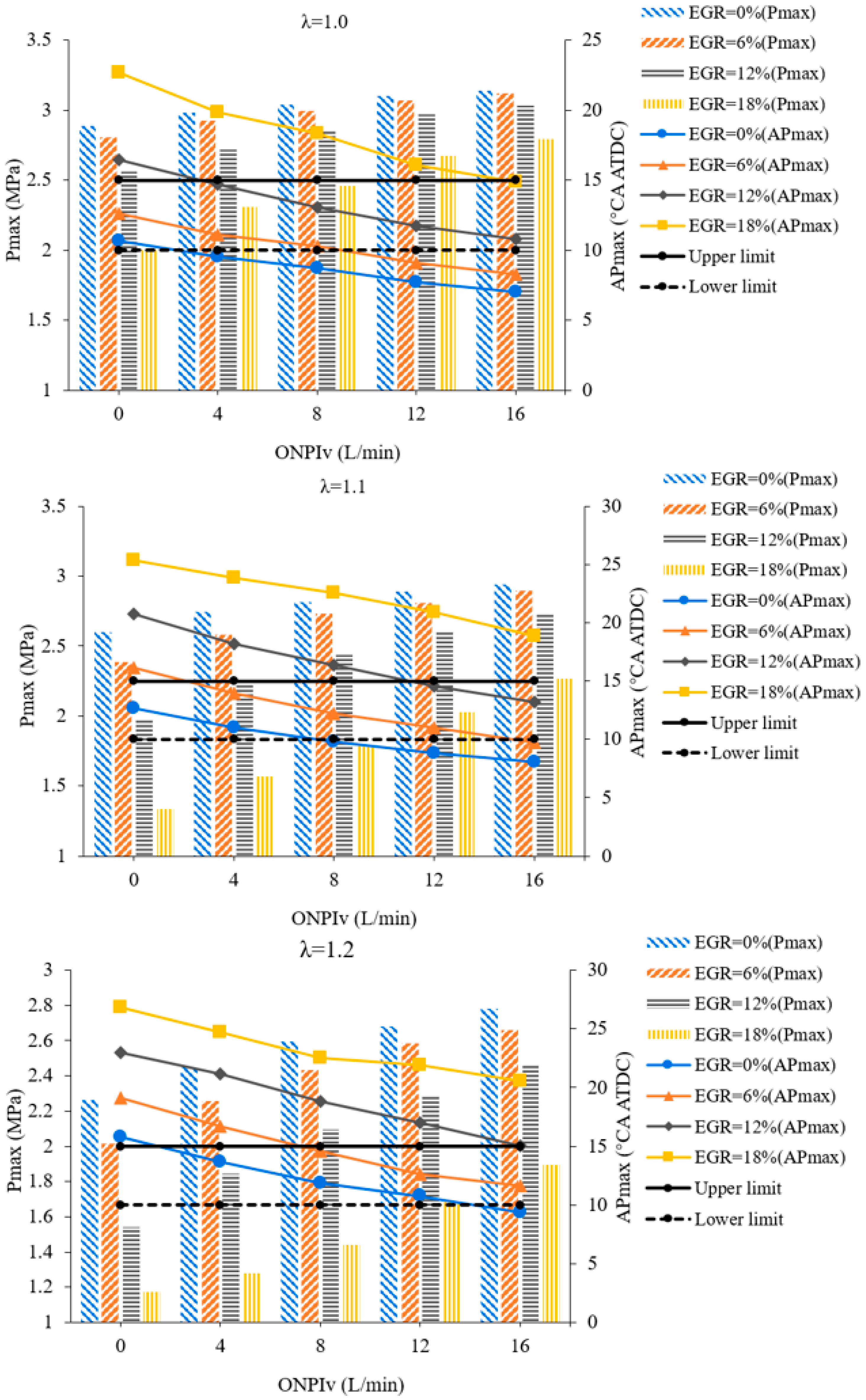
It is generally believed that 10° CA after compression top dead center (ATDC) ≤ APmax ≤ 15° CA ATDC is the best range for the engine. At this time, the engine can ensure a relatively good working condition. Figure 5 illustrates the change rules of APmax and Pmax with ONPlv at various λ and EGR ratios. As shown in Figure 5, as λ gradually increases, Pmax decreases and APmax is delayed. This is due to the reduction of the total amount of fuel participated in combustion, which reduces the heat release. Nevertheless, under three various λ conditions, as ONPIv continuously increases, Pmax increases and APmax decreases. As previously analyzed for CA 0–10 and CA 10–90, the utilization of oxyhydrogen can significantly reduce the duration of the combustion stage and enhance the constancy of volume during the combustion process, thus reducing APmax and increasing Pmax. When EGR is set to 6%, blending 8 L/min of oxyhydrogen can fully compensate for the adverse impact of exhaust gas on in-cylinder pressure. However, with the further increases of the EGR ratio, the hindrance of exhaust gas to combustion intensifies. Pmax shows an upward trend while APmax decreases. This indicates that more oxyhydrogen is needed to improve the combustion of the mixture. As shown in Figure 5, when λ = 1.0 and EGR = 12%, blending 12 L/min of oxyhydrogen can eliminate the adverse impact of EGR on cylinder pressure, and make Pmax and APmax close to the original engine; while blending 16 L/min of oxyhydrogen can increase Pmax by 5.13%, and make APmax slightly smaller. When EGR = 18% and λ = 1.0, blending 16 L/min of oxyhydrogen significantly increases Pmax and reduces APmax. However, Pmax has been still maintained the level below the original engine, and APmax exceeds than that of the original engine. It deserves the attention that APmax is in the optimum range only at “λ = 1.0 + EGR = 12% + ONPIv = 16 L/min”.
When EGR = 12% and λ = 1.1, 1.2, blending 16 L/min oxyhydrogen can increase Pmax by 4.88% and 9.04% respectively compared to the original engine, and make APmax paralleled to the original engine. This indicates that at least 16 L/min oxyhydrogen is required to make up for the deterioration of cylinder pressure caused by 12% EGR under the condition of lean–burn coupling EGR. However, when the EGR ratio increases to 18%, Pmax and APmax cannot be maintained at the original level even if blending 16 L/min oxyhydrogen. This indicates that when excessive exhaust gas is reintroduced into the cylinder, even if 16 L/min oxyhydrogen is blended, the reduce of Pmax and the increase of APmax caused by the adverse effect of EGR cannot be completely improved. On the one hand, excessive exhaust gas deteriorates the combustion environment, thereby reducing the Pmax of the engine and making it appear later. On the other hand, the hindrance of exhaust gas to combustion slows down the rate of reaction, which has an adverse impact on the evaporation and combustion of biobutanol and reduces mixture’s combustion quality. Especially at λ > 1.0, the superposition of diluted mixture and exhaust gas will have a greater negatory influence on the mixture combustion. It deserves attention that even after blending 16 L/min oxyhydrogen, APmax remains within the optimum range at EGR = 12% and λ = 1.1. However, at λ = 1.2, APmax is in the optimum range only when EGR = 6%. This shows that the optimum EGR ratio decreases with the increase of λ. To sum up, in terms of Pmax and APmax, the optimum control policy of EGR + BDI + ONPI + GPI engine under lean–burn conditions is “ONPIv = 16 L/min + EGR < 12%” and “ONPIv = 16 L/min + 6% ≤ EGR ≤ 12%” respectively.

3.4. IMEP

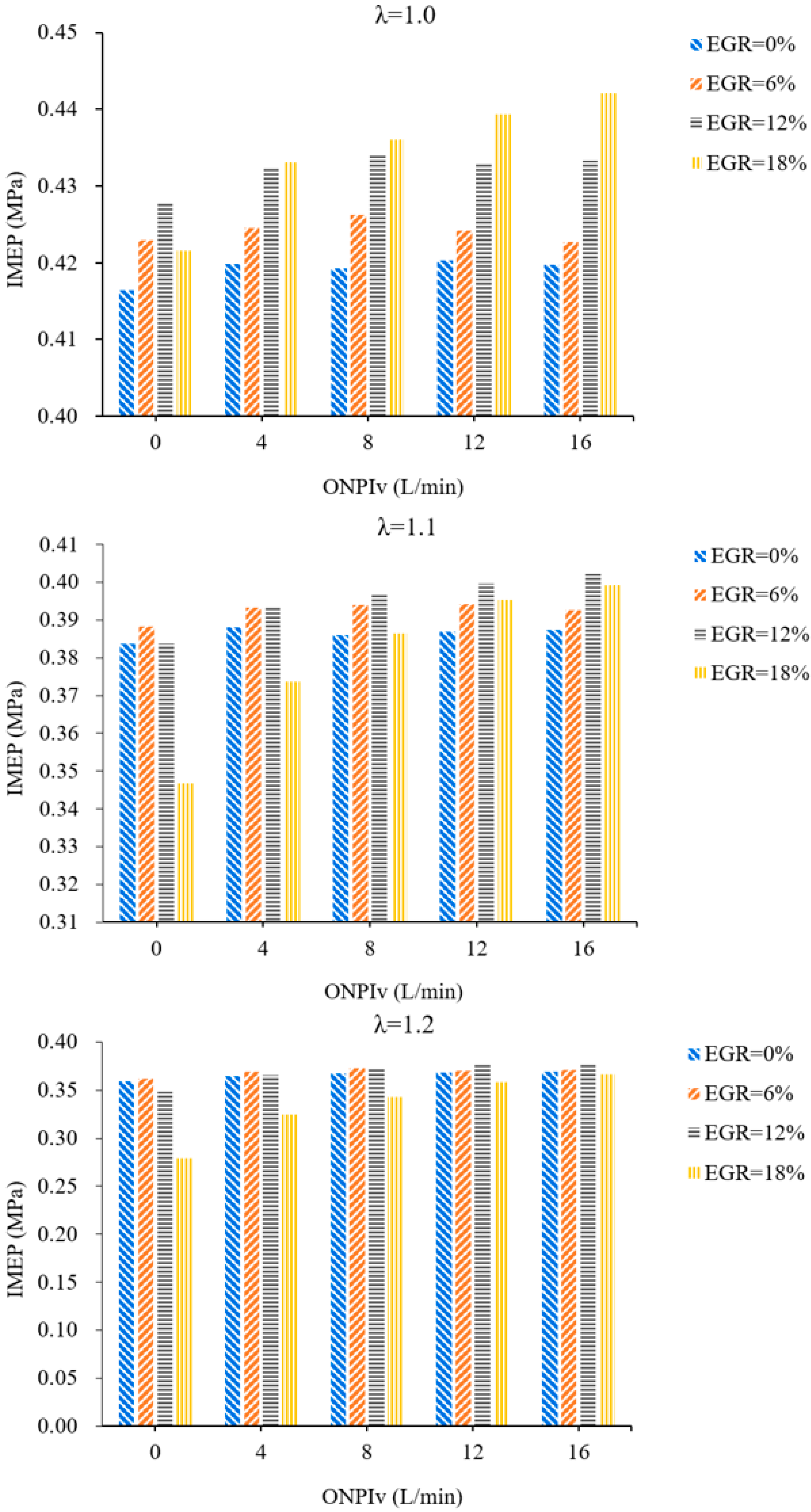
Figure 6 illustrates the change rules of IMEP with ONPIv under various EGR ratios and λ. Under λ = 1, when oxyhydrogen is not mixed, as EGR ratio increases, IMEP first rises and then reduces, and the optimum EGR ratio is 12%. The IMEP is 2.73% higher than that at EGR = 0%. This is because as EGR ratio increases, a larger throttle opening is needed to ensure sufficient air in the cylinder to keep λ at 1, thus reducing the pumping loss during the intake process and improving the IMEP. However, when the EGR ratio becomes larger and larger, more and more exhaust gas will disturb the combustion process and reduce the combustion stability. Moreover, the specific heat capacity of the mixture is positively correlated with the amount of exhaust gas, the increasing EGR ratio will lead to the lower combustion temperature, which deteriorates the evaporation and combustion of biobutanol. Therefore, when the EGR ratio exceeds 12%, the negative impact of EGR is the main factor, making IMEP lower. When oxyhydrogen is involved in combustion, as the EGR ratio increases, IMEP presents the trend of continuous increase. And the optimum EGR ratio rises from 12% to 18%. In addition, the larger the ONPIv, the stronger the influence of exhaust gas on IMEP. This means that blending oxyhydrogen can counteract the adverse impact of EGR on combustion and enable EGR to exert its ability to improve power performance. A higher ONPIv corresponds to a more pronounced improvement in IMEP through EGR. This shows that even at a large EGR ratio, blending oxyhydrogen can still ensure the stable forming of the flame kernel and the rapidly propagating flame. Moreover, the hydrogen ion (H+), oxygen ion (O2−), hydroxyl ion (OH), and hydroxyl group (·OH) all have a positive influence on the combustion of the mixture. In general, blending oxyhydrogen can improve the in-cylinder combustion atmosphere of the BDI + GPI + EGR engine, improve the engine’s tolerance to EGR, make EGR better play its advantages of reducing pumping loss, and effectually increase IMEP.
Under lean–burn conditions, IMEP increases as ONPIv increases. This is attributed to the active role of oxyhydrogen in enhancing the flame velocity of the mixture, thereby facilitating the combustion reaction and intensifying the exothermic process, ultimately leading to improved IMEP. Due to the reduction of total fuel involved in combustion, the IMEP is significantly reduced at lean–burn conditions. It is noteworthy that lean–burn can strengthen the negative impact of EGR on IMEP. Through the case study of unmixed oxyhydrogen, when the EGR ratio increases to 18%, the IMEP at lean–burn conditions drops sharply, which is 9.59% and 22.32% lower than that under EGR = 0%, respectively. The combustion environment is severely deteriorated at this stage, leading to the engine’s inability to function normally and stably. This can be attributed to the inhibitory influence of EGR on the combustion process and biobutanol evaporation. However, blending oxyhydrogen can accelerate the forming of the flame kernel and the combustion speed of the mixture, thus effectually improving the IMEP of EGR + BDI + ONPI + GPI engine under lean–burn conditions—especially when EGR = 18%, as ONPIv rises to 16 L/min, IMEP under λ = 1.1 and 1.2 respectively increases by 15.14% and 31.35% compared without oxyhydrogen. In addition, in terms of IMEP, blending oxyhydrogen can also improve the ONPI + BDI + GPI engine’s tolerance to the EGR ratio at lean–burn conditions. When ONPIv rises from 0 to 16 L/min, the optimum EGR ratio increases from 6% to 12%. At the same time, compared without EGR, the maximum IMEP at ONPIv = 16 L/min increases by 3.82% and 2.66%, respectively. However, the EGR ratio paralleled with the maximum IMEP cannot reach 18%, unlike that at λ = 1.0. This indicates that even the introduction of 16 L/min oxyhydrogen could not completely prevent the power loss caused by the EGR and lean–burn. In summary, blending oxyhydrogen enhances the power performance of the EGR + BDI + GPI engine. Although lean–burn decreases IMEP, the control policy of “λ = 1.1 + EGR = 12% + ONPIv = 16 L/min” can still maintain IMEP at the original engine level.

3.5. Coefficient of Indicated Mean Effective Pressure Variation (CoVIMEP)

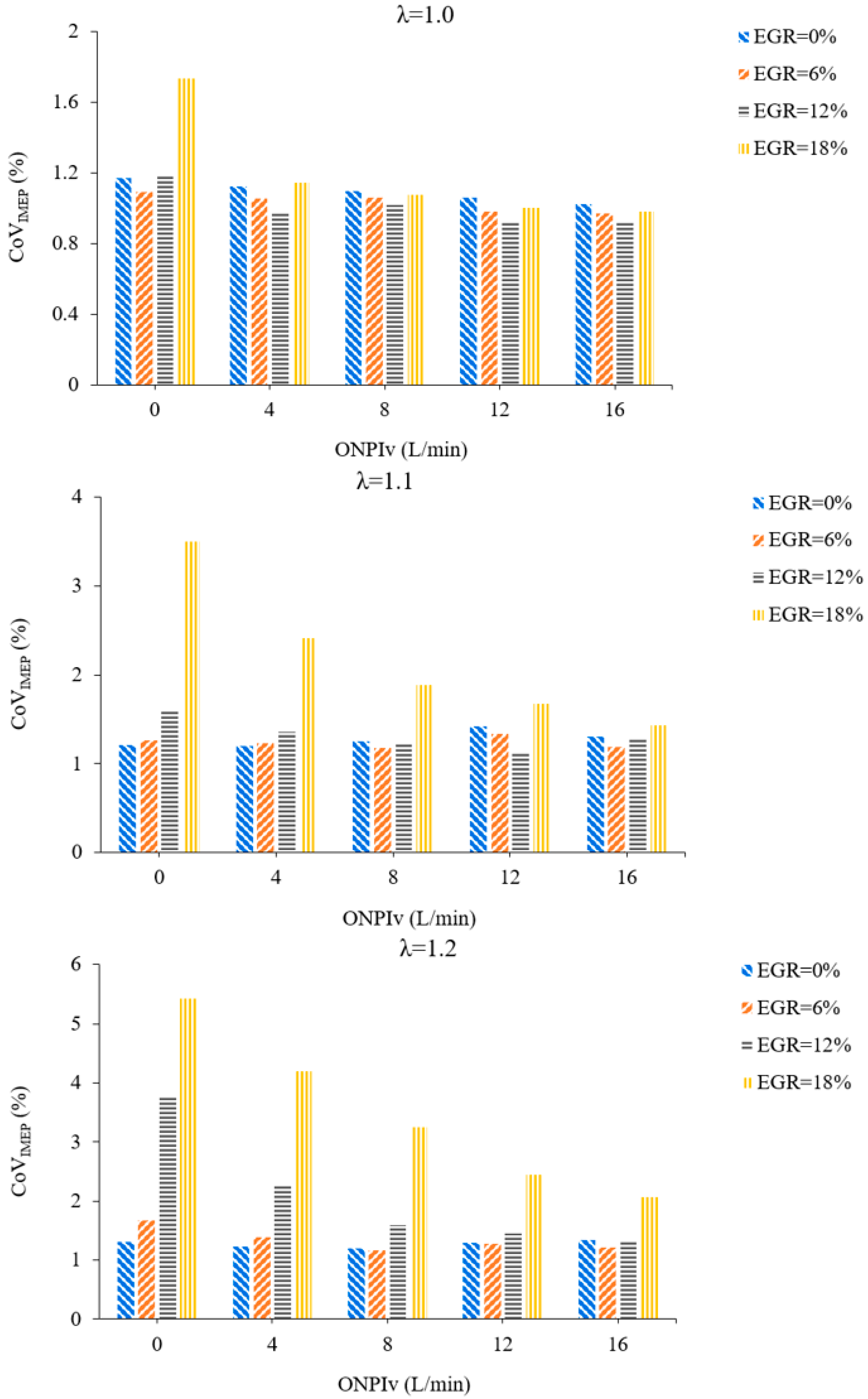
Figure 7 shows the change rules of CoVIMEP with ONPIv under various EGR ratios and λ. First of all, when λ = 1, as the EGR ratio gradually increases, CoVIMEP decreases first and then increases, but the range of change is not large, and the optimum EGR ratio increases from 6% to 12% after blending oxyhydrogen. Based on the previous analysis of IMEP, the BDI + GPI + EGR engine’s power performance can be increased by blending oxyhydrogen while still maintaining good combustion stability. However, with the increase of λ, CoVIMEP increases on the whole, which is attributed to the detrimental impact of the diluted mixture on flame kernel formation, flame propagation, and development, consequently compromising the stability of the combustion process. When λ increases to 1.2, the BDI + GPI + EGR engine without blending oxyhydrogen can only maintain a relatively low CoVIMEP when EGR ≤ 6%. Moreover, under lean–burn conditions, as the EGR ratio increases, the CoVIMEP of the BDI + GPI + EGR engine without oxyhydrogen increases sharply, and combustion stability decreases sharply. Especially when EGR = 18%, CoVIMEP of λ = 1.1, and 1.2 is 189.60% and 314.21% higher than the value of EGR = 0%, respectively. Oxyhydrogen is therefore provided as an auxiliary fuel to the BDI + GPI + EGR engine to increase combustion stability at high EGR ratios.
Under lean–burn conditions, CoVIMEP decreases continuously as ONPIv increases. According to previous studies on CA 0–90, it can be seen that oxyhydrogen has a significant effect on accelerating combustion speed and improving combustion stability. Its addition can significantly alleviate the deterioration of combustion caused by EGR, shorten the stage of continuous combustion, improving the stability of flame kernel forming, thus decreasing CoVIMEP. However, this reduction of CoVIMEP by oxyhydrogen is more obvious at a higher EGR ratio or larger λ. When EGR = 18% and ONPIv = 16 L/min, the CoVIMEP at λ = 1.0, 1.1, 1.2 is reduced by 43.34%, 59.11%, and 62.03% respectively compared with that without oxyhydrogen. This is because lean–burn and the high EGR ratio will have double the deterioration effect on in-cylinder combustion, and the variation of CoVIMEP is more sensitive to ONPIv. This suggests that the impact of oxyhydrogen on enhancing combustion stability increases in direct proportion to how diluted and unfavorable the combustion environment is. It is worth noting that CoVIMEP changes little with the increase of ONPIv when EGR ≤ 6%, most of them are maintained near the original engine level. In general, blending oxyhydrogen significantly improve the combustion stability of the BDI + GPI + EGR engine at a higher EGR ratio. As for CoVIMEP, when λ = 1.0, 1.1, EGR + BDI + ONPI + GPI engine can achieve efficient and stable combustion at “6% ≤ EGR ≤ 12% + ONPIv = 16 L/min”.

3.6. CO

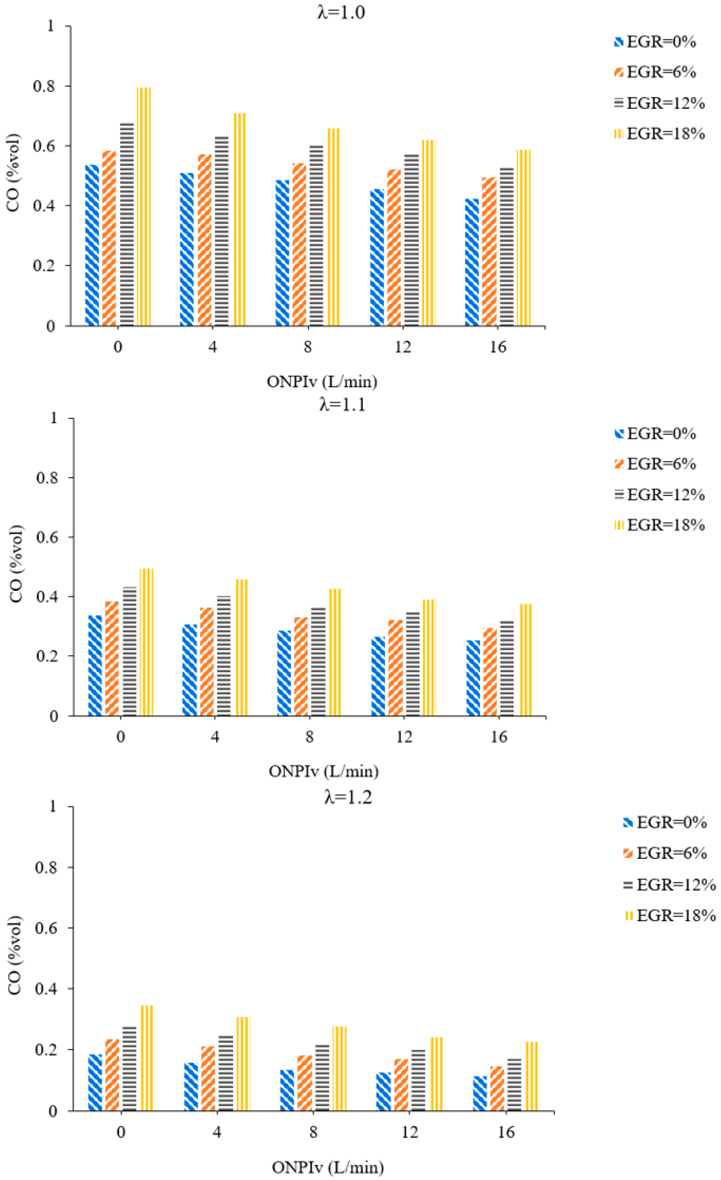
Figure 8 illustrates the change rules of CO emission with ONPIv at various λ and EGR ratios. As ONPIv gradually increases, CO emission decreases. This is because oxyhydrogen has a higher flame velocity than biobutanol and gasoline, adding oxyhydrogen as an auxiliary fuel to a cylinder causes the flame expand quickly across the entire combustion chamber when the spark plug ignites, accelerating combustion and lowering CO emission. Meanwhile, the oxyhydrogen’s active groups can facilitate the biobutanol–gasoline–air combustion interaction, so that biobutanol’s superior combustion properties can more effectually contribute to the combustion process and lower CO emission brought on by incomplete combustion. In addition, as EGR ratio increases, CO emission presents the increasing trend. On the one hand, the introduction of exhaust gas hinders combustion, causing more incomplete combustion, thus increasing CO emission; on the other hand, excessive exhaust gas raises the mixture’s heat capacity and reduces the combustion temperature, which makes it difficult for CO to oxidize later, leading to an increase in CO emission. After the introduction of EGR, the introduction of oxyhydrogen as a combustion-supporting fuel into the cylinder is an ideal solution to reduce CO emission.
When EGR = 6%, blending 12 L/min oxyhydrogen decreases CO emission to a level below that of the BDI + GPI mode. When EGR = 12%, blending 16 L/min oxyhydrogen decreases CO emission to a level below that of the BDI + GPI mode. When EGR = 18%, even if ONPIv rises to 16 L/min, the CO emission is still more than that of the BDI + GPI mode. This indicates that blending oxyhydrogen can alleviate the increasing CO emission, and when the EGR ratio continues to increase, more oxyhydrogen needs to be blended to optimize the incomplete combustion caused by exhaust gas. Meanwhile, the increase in λ leads to an elevation in the oxygen content within the cylinder, thereby facilitating further CO oxidation, and the overall level of CO emission are reduced. At lean–burn conditions, even if oxyhydrogen is not blended and EGR ratio increases to 18%, CO emission of the EGR + BDI + ONPI + GPI engine is still less than that of the original engine. This indicates that lean–burn can significantly reduce CO emission, and even its ability to reduce CO emission is stronger than that of blending oxyhydrogen. Considering the impact of ONPI, lean–burn and EGR on CO emission across all λ, it can be concluded that the optimum control policy for the EGR + BDI + ONPI + GPI engine is defined by the control policy “ONPIv = 16 L/min + EGR ≤ 12%”.

3.7. HC

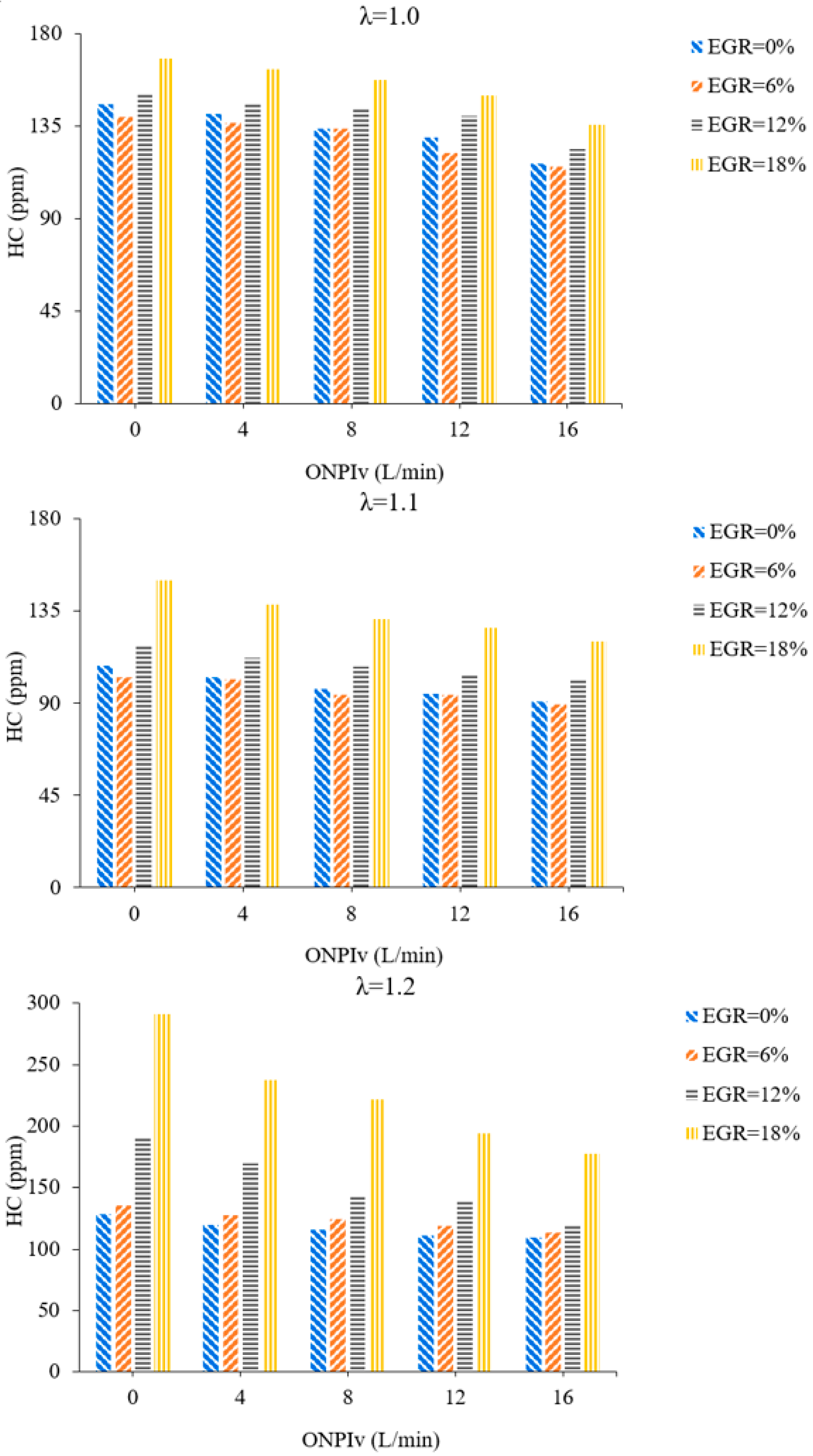
Figure 9 illustrates the change rules of HC emission with ONPIv at various EGR ratios and λ. HC emission continues to decrease as λ increases. This is because the increasing oxygen content plays a positive role in improving the combustion process. In addition, under three λ working conditions, as ONPIv gradually increases, HC emission presents a decreasing trend. On one hand, ONPI plays a crucial positive role in enhancing flame velocity and improving the combustion atmosphere, thereby mitigating HC emission resulting from misfire and incomplete combustion. On the other hand, oxyhydrogen exhibits a shorter quenching distance compared to gasoline and biobutanol, which optimizes oxidation reactions near cylinder walls and other crevices, consequently reducing HC emission influenced by quenching effects. Therefore, blending oxyhydrogen can effectually improve HC emission. When λ = 1 and 1.1, HC emission reduces slightly and then rises with the increase of EGR ratio, and gets the lowest value when EGR = 6%. When EGR = 6%, exhaust gas can preheat the mixture, which is advantageous for enhancing the thermodynamic environment and profit for further oxidation of HC, so HC emission will be slightly reduced. Nevertheless, with the continued augmentation of the EGR ratio, the retarding influence of exhaust gas on combustion is the dominant factor, which makes incomplete combustion and misfire increase, thus increasing HC emission. When λ = 1.2, with the augmentation of the EGR ratio, HC emission continues to increase. This is due to the fact that as λ rises to 1.2, the reduction in the in-cylinder mixture’s thickness not only lowers the combustion temperature but also compromises the quality of the combustion environment. Meanwhile the preheating effect of EGR on the mixture is weakened, and the retarding effect on combustion is strengthened, thus impairing the engine tolerance to EGR. Therefore, HC emission increases sharply. However, blending oxyhydrogen can improve the HC emission of the BDI + GPI + EGR engine under lean–burn conditions up to a point.
When λ = 1 and ONPIv = 16 L/min, even though the EGR ratio increases to 18%, HC emission is 136 ppm, exhibiting a reduction of 6.75% compared to the BDI + GPI mode. Therefore, in view of both maintaining low HC emission and making full use of EGR technology, the control policy of “EGR ≤ 18% + ONPIv = 16 L/min” is the best cooperation of EGR + BDI + ONPI + GPI engines at λ = 1. However, at lean–burn conditions, HC emissions are less than those of the original engine only at EGR ≤ 12% + ONPIv = 16 L/min. Meanwhile, HC emission is reduced by 6.29% and 6.83%, respectively, at λ = 1.1 and 1.2 when EGR = 12% and ONPIv = 16 L/min, compared to the original engine. It deserves attention that when the EGR ratio increases to 18%, HC emissions increase sharply. This is mainly due to the combined action of lean–burn and excess exhaust gas, which greatly reduces the catalytic conversion efficiency of HC emissions, thus affecting the efficient conversion of HC. In conclusion, in terms of HC emission, the control policy of “EGR ≤ 18% + ONPIv = 16 L/min” is the best cooperation of EGR + BDI + ONPI + GPI engines at λ = 1. The optimum cooperation of the EGR + BDI + ONPI + GPI engine at λ = 1.1, 1.2 is “6% ≤ EGR ≤ 12% + ONPIv = 16 L/min”.

3.8. NO

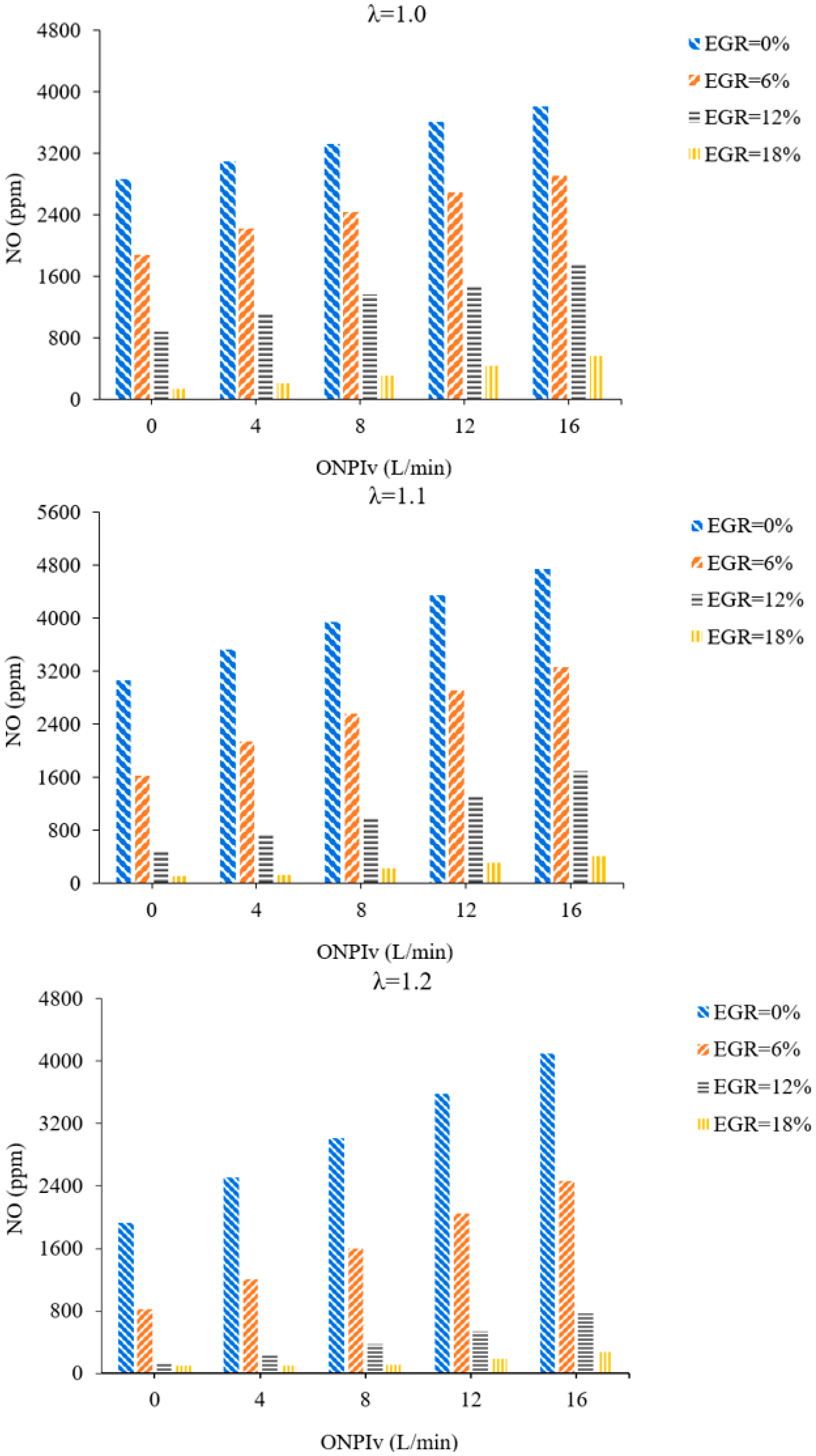
Figure 10 illustrates the change rules of NO emission with ONPIv at various λ and EGR ratios. As λ gradually increases, the NO emission presents the trend of slightly increasing first and then decreasing significantly. This is mainly because when λ increases to 1.1, a high temperature oxygen rich environment is formed in the combustion chamber, and NO emission increases slightly. However, when λ exceeds to 1.1, the diluted mixture deteriorates the in-cylinder combustion, destroys the high temperature environment, and the NO emission drop sharply. Moreover, NO emission continues to increase with the increasing ONPIv. This is because blending oxyhydrogen can promote the combustion reaction, increase combustion temperature. Therefore, the in-cylinder temperature can be kept above 1800 K for a long time, thus increasing the NO emission. At λ = 1, the NO emissions increase by 59.48 ppm for every addition of 1 L/min oxyhydrogen. At lean–burn conditions, the NO emissions increase by 119.94 ppm on average for every addition of 1 L/min oxyhydrogen. This is because at lean–burn conditions, blending oxyhydrogen will increase the oxygen content and maintain the high in-cylinder temperature for a longer time, so more NO emissions will be generated.
Moreover, as the EGR ratio gradually increases, NO emission shows the trend of significant decrease. Based on the previous research of Pmax and APmax, the increasing amount of exhaust gas deteriorates the combustion environment, which makes the combustion pressure and temperature decrease significantly, and is conducive to inhibiting the generation of NO. At λ = 1.0, when the EGR ratio increases from 0 to 18%, the NO emission decreases by 151.30 ppm on average when the EGR ratio increases by 1%. Under lean–burn conditions, the average NO emissions decrease by 133.19 ppm when the EGR ratio increases by 1%. In addition, under the condition of high EGR ratios, the increasing trend of NO emission caused by oxyhydrogen has been alleviated. This shows that in terms of NO emission, EGR has an obvious compensation effect on blending oxyhydrogen. Therefore, through EGR technology, the release of NO emission caused by mixed combustion of oxyhydrogen can be effectually inhibited. According to the previous research results, the blending of 16 L/min oxyhydrogen can significantly improve engine power and combustion characteristics of the EGR + BDI + ONPI + GPI engine. When ONPIv rises to 16 L/min, the NO emission under three types of λ working conditions are only maintained at the initial value after the EGR ratio reaches 12%. In particular, when EGR = 18% and ONPIv = 16 L/min, the NO emission of λ = 1.0, 1.1, 1.2 are 79.96%, 86.42%, and 85.63% less than those of the original engine. Taking all factors into consideration, the optimum cooperation of the EGR + BDI + ONPI + GPI engine is “1.1 ≤ λ ≤ 1.2 + EGR ≥ 12% + ONPIv = 16 L/min”.

4. Conclusions

This paper explores the cooperative interaction of lean–burn coupled EGR on the BDI + ONPI + GPI engine. The experimental variables include three λ (1.0, 1.1, 1.2), five ONPIv (0, 4, 8, 12, 16 L/min), and four EGR ratios (0%, 6%, 12%, 18%). The main conclusions are as follows:
(1)
Increasing the ONPI injection flow rate can improve the peak pressure and heat release rate inside the cylinder. An increase in EGR rate has a suppressive effect on combustion, resulting in a decrease in cylinder pressure and peak heat release rate. As λ increases, the peak cylinder pressure and heat release rate decrease, and the corresponding crankshaft angle is delayed.
(2)
Lean–burn reduces IMEP and exacerbates the negative impact of EGR. However, the introduction of oxyhydrogen has an obvious effect on IMEP improvement, especially under a high EGR ratio. Moreover, under lean–burn conditions, as the ONPIv rises from 0 to 16 L/min, the optimum EGR ratio rises from 6% to 12%. In addition, the control policy of “EGR = 12% + ONPIv = 16 L/min + λ=1.1” effectively maintains the IMEP to the original engine level.
(3)
As ONPIv increases, CA 0–10 and CA 10–90 both continuously shorten, especially under a high EGR ratio and lean–burn conditions. Under all λ, “EGR < 12% + 12 L/min ≤ ONPIv ≤ 16 L/min” can diminish ignition delay and combustion duration to a level below that of the BDI + GPI mode.
(4)
As EGR ratio increases, Pmax decreases and APmax increases, while as the ONPIv increases, Pmax and APmax show the opposite trend, which indicates that ONPI has a substantial impact on enhancing the mixture combustion after blending exhaust gas.
(5)
Oxyhydrogen significantly reduces the CoVIMEP of the BDI + GPI + EGR engine. When λ = 1.0, 1.1, 1.2 and EGR = 18%, blending 16 L/min of oxyhydrogen reduces CoVIMEP by 43.34%, 59.11%, and 62.03% compared with that without blending oxyhydrogen, respectively.
(6)
CO emissions increase with the increasing EGR ratio, while they decrease with the increasing ONPIv. For CO emission, “EGR ≤ 12% + ONPIv = 16 L/min” is the optimal control strategy for the EGR + BDI + ONPI + GPI engine.
(7)
Oxyhydrogen has a remarkable effect on reducing HC emission of the BDI + GPI + EGR engine, especially under high EGR ratio conditions. The optimum cooperation of the EGR + BDI + ONPI + GPI engine at λ = 1.1, 1.2 is “ONPIv = 16 L/min + 6% ≤ EGR ≤ 12%”.
(8)
As ONPIv gradually increases, NO emission presents the trend of obvious increase. However, the intervention of EGR can reduce the NO emission. The optimum cooperation of the EGR + BDI + ONPI + GPI engine is “1.1 ≤ λ ≤1.2 + EGR ≥ 12% + ONPIv = 16 L/min”.
(9)
In summary, based on the biobutanol/gasoline composite injection engine, ONPI and EGR can further optimize the performance of the engine. On the one hand, oxyhydrogen improves the tolerance of the engine to EGR and enables the engine to operate stably at high EGR rates. On the other hand, the integration of lean–burn and EGR can diminish the high NO emission caused by ONPI. EGR-coupled lean–burn can make the engine have excellent combustion and emission characteristics while obtaining lower NO emission.

Author Contributions

Conceptualization, J.H. and F.X.; methodology, Z.Z. (Zhe Zhao); software, Z.Z. (Ziheng Zhao); validation, Y.S., Y.L. (Yu Liu) and X.L.; formal analysis, Z.Z. (Zhe Zhao) and Z.Z. (Ziheng Zhao); investigation, B.J.; resources, Z.Z. (Zhe Zhao); data curation, Z.J. and Z.Z. (Ziheng Zhao); writing—original draft preparation, J.H. and Y.L. (Yi Lin); writing—review and editing, X.W. and H.G.; visualization, Z.Z. (Zhe Zhao); supervision, Y.L. (Yi Lin); project administration, H.G.; funding acquisition, Z.Z. (Zhe Zhao). All authors have read and agreed to the published version of the manuscript.

Funding

This work was supported by the Jilin Provincial Scientific and Technological Development Program (No. 20240101140JC), the National Natural Science Foundation of China (NSFC) (No. 52506138), the Yangtze River Delta Science and Technology Innovation Community Joint Research Plan (No. 2025ZY03010), the National Undergraduate Training Program on Innovation and Entrepreneurship (No. 202510183143).

Data Availability Statement

Data available on request due to restrictions. The data is the result figure in the article, and other content is temporarily not convenient to disclose as the related research has not yet been fully completed.

Conflicts of Interest

The authors declare no conflicts of interest.

Abbreviations

The following abbreviations are used in this manuscript:
SI Spark ignition
ONPINegative pressure indraft of oxyhydrogen
BDIDirect injection of biobutanol
GPIPort injection of gasoline
BDIrBiobutanol direct injection ratio
ONPIvOxyhydrogen negative pressure indraft volume
EGRExhaust gas recirculation
IMEPIndicated mean effective pressure
PmaxPeak in-cylinder pressure
APmaxCrank angle corresponding to Pmax
CACrank angle
BTDCBefore compression top dead center
λExcess air coefficient
ATDCAfter compression top dead center
CoVIMEPCoefficient of indicated mean effective pressure variation
NONitric oxide
NOxNitrogen oxides
COCarbon monoxide
HCHydrocarbon
HRRHeat release rate

References

  1. Feng, R.H.; Hua, Z.Y.; Zhao, Z.C.; Li, F.G.; Shu, X.; Luo, L.C.; Zhai, H.K. A comprehensive performance evaluation of a fuel-cell hybrid electric heavy-duty truck through energy flow experiment under user-defined driving test cycles. Case Stud. Therm. Eng. 2026, 80, 107819. [Google Scholar] [CrossRef] [Scilit]
  2. Huang, S.-Y.; Zhou, J.; Liu, S.-J.; Peng, H.-Y.; Yuan, X.-Q. Continuous rotating detonation engine fueled by ammonia. Energy 2022, 252, 123911. [Google Scholar] [CrossRef] [Scilit]
  3. Nakajima, S.; Saiki, R.; Goryozono, Y. Development of an Engine for Flexible Fuel Vehicles (FFV). SAE Technical Paper, 5 August 2007. [CrossRef] [Scilit]
  4. Abdel-Rahman, A.A.; Osman, M.M. Experimental investigation on varying the compression ratio of SI engine working under various ethanol–gasoline fuel blends. Int. J. Energy Res. 1997, 21, 31–40. [Google Scholar] [CrossRef]
  5. Szulczyk, K.R. Which is a better transportation fuel—Butanol or ethanol. Int. J. Energy Environ. 2010, 1, 501–512. [Google Scholar]
  6. Debnath, R.; Sastry, G.R.K.; Dash, A.; Singh, R.; Rai, R.N. An Experimental-Based Comparative Analysis of Undi Biodiesel Blends with Diesel in a DI Engine Operating with AHP Method. Energy Exergy Sustain. Clean Environ. 2022, 1, 141–151. [Google Scholar]
  7. Li, Y.; Gong, J.K.; Yuan, W.H.; Fu, J.; Zhang, B.; Li, Y.Q. Experimental investigation on combustion, performance, and emission characteristics of butanol as an oxygenate in a spark ignition engine. Adv. Mech. Eng. 2017, 9, 1687814016688848. [Google Scholar] [CrossRef] [Scilit]
  8. Roy, M.M.; Wang, W.; Alawi, M. Performance and emissions of a diesel engine fueled by biodiesel–diesel, biodiesel–diesel-additive and kerosene–biodiesel blends. Energy Convers. Manag. 2014, 84, 164–173. [Google Scholar] [CrossRef] [Scilit]
  9. Pukalskas, S.; Kriaučiūnas, D.; Rimkus, A.; Przybyła, G.; Droździel, P.; Barta, D. Effect of Hydrogen Addition on the Energetic and Ecologic Parameters of an SI Engine Fueled by Biogas. Appl. Sci. 2021, 11, 742. [Google Scholar] [CrossRef] [Scilit]
  10. Zhong, W.H.; Zhang, Y.H.; Lou, D.M.; Fang, L.; Hu, Z.Y.; Tan, P.Q. Combustion stability and emission performance of a DI hydrogen engine: The role of excess air ratio (λ) boundaries under varying operating conditions. Int. J. Hydrogen Energy 2026, 225, 154384. [Google Scholar] [CrossRef] [Scilit]
  11. Yan, F.W.; Xu, L.; Wang, Y. Application of hydrogen enriched natural gas in spark ignition IC engines: From fundamental fuel properties to engine performances and emissions. Renew. Sustain. Energy Rev. 2018, 82, 1457–1488. [Google Scholar] [CrossRef] [Scilit]
  12. Chen, Z.; Yang, F.; Xue, S.; Wu, Z.K.; Liu, J.P. Impact of higher n-butanol addition on combustion and performance of GDI engine in stoichiometric combustion. Energy Convers. Manag. 2015, 106, 385–392. [Google Scholar] [CrossRef] [Scilit]
  13. Tian, Z.; Zhen, X.D.; Wang, Y.; Liu, D.M.; Li, X.Y. Combustion and emission characteristics of n-butanol–gasoline blends in SI direct injection gasoline engine. Renew. Energy 2020, 146, 267–279. [Google Scholar] [CrossRef] [Scilit]
  14. Zhen, X.D.; Wang, Y.; Liu, D.M. Bio-butanol as a new generation of clean alternative fuel for SI (spark ignition) and CI (compression ignition) engines. Renew. Energy 2020, 147, 2494–2521. [Google Scholar] [CrossRef] [Scilit]
  15. Feng, R.H.; Yang, J.; Zhang, D.M.; Deng, B.L.; Fu, J.Q.; Liu, J.P.; Liu, X.Q. Experimental study on SI engine fuelled with butanol–gasoline blend and H2O addition. Energy Convers. Manag. 2013, 74, 192–200. [Google Scholar] [CrossRef] [Scilit]
  16. He, B.Q.; Chen, X.; Lin, C.-L.; Zhao, H. Combustion characteristics of a gasoline engine with independent intake port injection and direct injection systems for n-butanol and gasoline. Energy Convers. Manag. 2016, 124, 556–565. [Google Scholar] [CrossRef] [Scilit]
  17. Feng, D.Q.; Wei, H.Q.; Pan, M.Z.; Zhou, L.; Hua, J.X. Combustion performance of dual-injection using n-butanol direct-injection and gasoline port fuel-injection in a SI engine. Energy 2018, 160, 573–581. [Google Scholar] [CrossRef] [Scilit]
  18. Yu, X.M.; Guo, Z.Z.; He, L.; Dong, W.; Sun, P.; Shi, W.B.; Du, Y.D.; He, F.S. Effect of gasoline/n-butanol blends on gaseous and particle emission from an SI direct injection engine. Fuel 2018, 229, 1–10. [Google Scholar] [CrossRef] [Scilit]
  19. Chen, Y.J.; Lou, D.M.; Cheng, L.; Hu, Z.Y.; Tan, P.Q. Performance and Emission Characteristics of the Butanol–Gasoline Blends in an EFI Gasoline Engine. Adv. Mater. Res. 2013, 788, 709–715. [Google Scholar] [CrossRef] [Scilit]
  20. Şahin, Z.; Aksu, O.N.; Bayram, C. The effects of n-butanol/gasoline blends and 2.5% n-butanol/gasoline blend with 9% water injection into the intake air on the SIE engine performance and exhaust emission. Fuel 2021, 303, 121210. [Google Scholar] [CrossRef] [Scilit]
  21. Shang, W.W.; Yu, X.M.; Shi, W.B.; Xing, X.X.; Guo, Z.Z.; Du, Y.D.; Liu, H.Y.; Wang, S. Effect of exhaust gas recirculation and hydrogen direct injection on combustion and emission characteristics of a n-butanol SI engine. Int. J. Hydrogen Energy 2020, 45, 17961–17974. [Google Scholar] [CrossRef] [Scilit]
  22. Yu, X.M.; Du, Y.D.; Sun, P.; Liu, L.; Wu, H.M.; Zuo, X. Effects of hydrogen direct injection strategy on characteristics of lean-burn hydrogen–gasoline engines. Fuel 2017, 208, 602–611. [Google Scholar] [CrossRef] [Scilit]
  23. Su, T.; Ji, C.W.; Wang, S.F.; Cong, X.Y.; Shi, L.; Yang, J.X. Improving the lean performance of an n-butanol rotary engine by hydrogen enrichment. Energy Convers. Manag. 2018, 157, 96–102. [Google Scholar] [CrossRef] [Scilit]
  24. Ye, Y.X.; Gao, W.Z.; Li, Y.; Zhang, P.; Cao, X.D. Numerical study of the effect of injection timing on the knock combustion in a direct-injection hydrogen engine. Int. J. Hydrogen Energy 2020, 45, 27904–27919. [Google Scholar] [CrossRef] [Scilit]
  25. Yu, X.M.; Li, G.T.; Dong, W.; Shang, Z.; Guo, Z.Z.; Li, Y.N.; Li, D.C.; Zhao, Z. Numerical study on effects of hydrogen direct injection on hydrogen mixture distribution, combustion and emissions of a gasoline/hydrogen SI engine under lean burn condition. Int. J. Hydrogen Energy 2020, 45, 2341–2350. [Google Scholar] [CrossRef] [Scilit]
  26. Al-Rousan, A.A. Reduction of fuel consumption in gasoline engines by introducing HHO gas into intake manifold. Int. J. Hydrogen Energy 2010, 35, 12930–12935. [Google Scholar] [CrossRef] [Scilit]
  27. Subramanian, B.; Ismail, S. Production and use of HHO gas in IC engines. Int. J. Hydrogen Energy 2018, 43, 7140–7154. [Google Scholar] [CrossRef] [Scilit]
  28. Ismail, T.M.; Ramzy, K.; Abelwhab, M.N.; Elnaghi, B.E.; Abd El-Salam, M.; Ismail, M.I. Performance of hybrid compression ignition engine using hydroxy (HHO) from dry cell. Energy Convers. Manag. 2018, 155, 287–300. [Google Scholar] [CrossRef] [Scilit]
  29. Karagoz, Y.; Yuca, N.; Sandalci, T.; Dalkılıç, A.S. Effect of hydrogen and oxygen addition as a mixture on emission and performance characteristics of a gasoline engine. Int. J. Hydrogen Energy 2015, 40, 8750–8760. [Google Scholar] [CrossRef] [Scilit]
  30. Zhao, Z.; Huang, Y.; Yu, X.M.; Li, M.; Zhang, Z.H.; Guo, Z.Z.; Wang, T.Q.; Li, D.C. Comparative study on combustion and emission of SI engine blended with oxyhydrogen by various injection modes of gasoline. Int. J. Hydrogen Energy 2022, 47, 34273–34290. [Google Scholar] [CrossRef] [Scilit]
  31. Abhilash, R.; Gopalakrishna, K.; Venkatesh, K. Performance evaluation of an IC Engine using Oxyhydrogen as a fuel supplement. J. Sci. Ind. Res. 2015, 74, 176–179. [Google Scholar]
  32. Masjuki, H.H.; Ruhul, A.M.; Mustafi, N.N.; Kalam, M.A.; Arbab, M.I.; Rizwanul Fattah, I.M. Study of production optimization and effect of hydroxyl gas on a CI engine performance and emission fueled with biodiesel blends. Int. J. Hydrogen Energy 2016, 41, 14519–14528. [Google Scholar] [CrossRef] [Scilit]
  33. Gad, M.S.; Abdel Razek, S.M. Impact of oxyhydrogen produced from dry and wet cell electrolyzers on diesel engine performance, emission and combustion characteristics. Int. J. Hydrogen Energy 2021, 46, 22277–22291. [Google Scholar] [CrossRef] [Scilit]
  34. Salek, F.; Zamen, M.; Hosseini, S.V.; Babaie, M. Novel hybrid system of pulsed oxyhydrogen generator/TEG waste heat recovery for CO reduction of a gasoline engine. Int. J. Hydrogen Energy 2020, 45, 23576–23586. [Google Scholar] [CrossRef] [Scilit]
  35. Yilmaz, A.C.; Uludamar, E.; Aydin, K. Effect of hydroxy (HHO) gas addition on performance and exhaust emissions in compression ignition engines. Int. J. Hydrogen Energy 2010, 35, 11366–11372. [Google Scholar] [CrossRef] [Scilit]
  36. Baltacioglu, M.K.; Arat, H.T.; Ozcanli, M.; Aydin, K. Experimental comparison of pure hydrogen and oxyhydrogen (hydroxy) enriched biodiesel (B10) fuel in a commercial diesel engine. Int. J. Hydrogen Energy 2016, 41, 8347–8353. [Google Scholar] [CrossRef] [Scilit]
  37. Khan, M.B.; Kazim, A.H.; Farooq, M.; Javed, K.; Shabbir, A.; Zahid, R.; Fatima, S.; Danish, M.R.; Ali, Q.; Chaudhry, I.A.; et al. Impact of oxyhydrogen gas enrichment and high purity biodiesel on the performance of a 315 cc diesel engine. Int. J. Hydrogen Energy 2021, 46, 19663–19664. [Google Scholar] [CrossRef] [Scilit]
  38. Elgarhi, I.; El-Kassaby, M.M.; Eldrainy, Y.A. Enhancing compression ignition engine performance using biodiesel/diesel blends and oxyhydrogen gas. Int. J. Hydrogen Energy 2020, 45, 25409–25425. [Google Scholar] [CrossRef] [Scilit]
  39. Zhao, Z.; Huang, Y.; Yu, X.M.; Guo, Z.Z.; Li, M.; Wang, T.Q. Effect of brown gas (oxyhydrogen) addition on combustion and emission in gasoline engine with exhaust gas recirculation (EGR) and gasoline direct injection. J. Clean. Prod. 2022, 360, 132078. [Google Scholar] [CrossRef] [Scilit]
  40. Baltacioglu, M.K.; Kenanoglu, R.; Aydin, K. Oxyhydrogen enrichment of bio-diesohol fuel blends in a single cylinder diesel engine. Int. J. Hydrogen Energy 2019, 44, 18993–19004. [Google Scholar] [CrossRef] [Scilit]
  41. Ji, C.W.; Wang, S.F. Combustion and emission performance of a hydrogen engine at idle and lean conditions. Int. J. Energy Res. 2010, 37, 346–355. [Google Scholar] [CrossRef] [Scilit]
  42. Hardalupas, Y.; Taylor, A.; Whitelaw, J.H.; Ishii, K.; Miyano, K.; Urata, Y. Ifluence of Injection Timing on In-Cylinder Fuel Distribution in a Honda VTEC-E Engine. SAE Trans. 1995, 104, 433–455. [Google Scholar]
  43. Quader, A.A. What Limits Lean Operation in Spark Ignition Engines—Flame Initiation or Propagation? SAE Trans. 1976, 85, 2374–2387. [Google Scholar]
  44. Peters, B.D.; Quader, A.A. Wetting the appetite of spark ignition engines for lean combustion. SAE Technical Paper, 1 February 1978.
  45. Quader, A.A. The Axially-Stratified-Charge Engine. SAE Trans. 1982, 91, 479–506. [Google Scholar]
  46. Yu, X.M.; Guo, Z.Z.; He, L.; Dong, W.; Sun, P.; Du, Y.D.; Li, Z.; Yang, H.; Wang, S.; Wu, H.M. Experimental study on lean-burn characteristics of an SI engine with hydrogen/gasoline combined injection and EGR. Int. J. Hydrogen Energy 2019, 44, 13988–13998. [Google Scholar] [CrossRef] [Scilit]
  47. Yu, X.M.; Li, G.T.; Du, Y.D.; Guo, Z.Z.; Shang, Z.; He, F.S.; Shen, Q.X.; Li, D.C.; Li, Y.N. A comparative study on effects of homogeneous or stratified hydrogen on combustion and emission of a gasoline/hydrogen SI engine. Int. J. Hydrogen Energy 2019, 44, 25975–25984. [Google Scholar] [CrossRef] [Scilit]
  48. Shang, Z.; Yu, X.M.; Shi, W.B.; Huang, S.; Li, G.T.; Guo, Z.Z.; He, F.S. Numerical research on effect of hydrogen blending fractions on idling performance of an n-butanol ignition engine with hydrogen direct injection. Fuel 2019, 258, 116082. [Google Scholar] [CrossRef] [Scilit]
  49. Chen, Z.; Yu, X.M.; Shi, W.; Li, G.T.; Wang, S.; Guo, Z.Z.; Chen, A.X.; Jin, Y.T. Effects of Hydrogen Addition Ratios on Cycle-by-Cycle Changes of a Duel-Fuel Spark Ignition Engine with Ethanol Intake Port Injection and Hydrogen Direct Injection under Various Excess Air Coefficients. Energy Fuels 2020, 34, 3709–3724. [Google Scholar] [CrossRef] [Scilit]
  50. Yu, X.M.; Li, D.C.; Yang, S.L.; Sun, P.; Guo, Z.Z.; Yang, H.; Li, Y.N.; Wang, T.Q. Effects of hydrogen direct injection on combustion and emission characteristics of a hydrogen/Acetone–Biobutanol–Ethanol dual-fuel spark ignition engine under lean-burn conditions. Int. J. Hydrogen Energy 2020, 45, 34193–34203. [Google Scholar] [CrossRef] [Scilit]
  51. Su, J.; Min, X.; Li, T.; Gao, Y.; Wang, J.S. Combined effects of cooled EGR and a higher geometric compression ratio on thermal efficiency improvement of a downsized boosted spark-ignition direct-injection engine. Energy Convers. Manag. 2014, 78, 65–73. [Google Scholar] [CrossRef] [Scilit]
  52. Wei, H.Q.; Feng, D.Q.; Pan, J.Y.; Shao, A.F.; Pan, M.Z. Knock characteristics of SI engine fueled with n-biobutanol in control policy with various EGR ratios. Energy 2017, 118, 190–196. [Google Scholar] [CrossRef] [Scilit]
  53. Zhang, Z.J.; Zhang, H.Y.; Wang, T.Y.; Jia, M. Effects of tumble combined with EGR (exhaust gas recirculation) on the combustion and emission in a spark ignition engine at part loads. Energy 2014, 65, 18–24. [Google Scholar] [CrossRef] [Scilit]
  54. Bogarra, M.; Herreros, J.M.; Tsolakis, A.; York, A.P.E.; Millington, P.J.; Martos, F.J. Impact of Exhaust Gas Fuel Reforming and Exhaust Gas Recirculation on Particulate Matter Morphology in Gasoline Direct Injection Engine. J. Aerosol Sci. 2017, 103, 1–14. [Google Scholar] [CrossRef] [Scilit]
Figure 1. Experimental setup schematic diagram.
Energies 19 01544 g001
Figure 2. The specific experimental procedure.
Energies 19 01544 g002
Figure 3. Change rules of cylinder pressure and HRR at various ONPIv, EGR ratios, and λ.
Energies 19 01544 g003
Figure 4. Change rules of CA 0–10 and CA 10–90 with ONPIv at various EGR ratios and λ.
Energies 19 01544 g004
Figure 5. Change rules of APmax and Pmax with ONPlv at various λ and EGR ratios.
Energies 19 01544 g005
Figure 6. Change rules of IMEP with ONPIv at various EGR ratios and λ.
Energies 19 01544 g006
Figure 7. Change rules of CoVIMEP with ONPIv at various EGR ratios and λ.
Energies 19 01544 g007
Figure 8. Change rules of CO emission with ONPIv at various EGR ratios and λ.
Energies 19 01544 g008
Figure 9. Change rules of HC emission with ONPIv at various EGR ratios and λ.
Energies 19 01544 g009
Figure 10. Change rules of NO emission with ONPIv at various EGR ratios and λ.
Energies 19 01544 g010
Table 1. Detailed data of experimental engine.
SI Engine TypeTitle 2four-Cylinder, Water-Cooled, BDI + GDI + ONPI
Displacement2.0 L
Compression9.6:1
Stroke92.8 mm
Bore82.5 mm
Maximum power (4000 rpm)137 kW
Maximum torque (1500–4000 rpm)320 N·m
Table 2. Detailed of all testing equipment.
ParametersTypePrecisionRange
TorqueCW160≤±0.28 N·m0–600 N·m
SpeedCW160≤±1 r/min0–6000 r/min
Cylinder pressureAVL-GU13Z-24≤±0.5%0–20 MPa
Crank angleKistler-2614B≤±0.5°0–720°
Oxyhydrogen generatorQHL6/24N≤0.01 L/min0–2 L/min
COHORIBA-MEXA584L≤±0.01%0–10% vol
NOHORIBA-MEXA584L≤±1 ppm0–5000 ppm vol
HCHORIBA-MEXA584L≤±1 ppm0–20,000 ppm vol
Mass flow meterDF-2420≤±0.01 g/s0.2–82 kg/h
Table 3. Test scheme.
Test InvariantsTest Variables
n = 1500 rpmEGR ratio = 0%, 6%, 12%, 18%
MAP = 42 kPaλ = 1.0, 1.1, 1.2
GPI timing = 340° CA BTDCONPIv = 0, 4, 8, 12, 16 L/min
BDI timing = 300° CA BTDC
GPI pressure = 0.5 MPa
BDI pressure = 9 MPa
BDIr = 40%
Spark timing = 15° CA BTDC
Disclaimer/Publisher’s Note: The statements, opinions and data contained in all publications are solely those of the individual author(s) and contributor(s) and not of MDPI and/or the editor(s). MDPI and/or the editor(s) disclaim responsibility for any injury to people or property resulting from any ideas, methods, instructions or products referred to in the content.