Article

Stability Control of the DC/DC Converter in DC Microgrids Considering Negative Damping and Parameter Uncertainties

Key Laboratory of Military Special Power Supply, Communication NCO Academy of PLA, Chongqing 400035, China
*
Author to whom correspondence should be addressed.
Energies 2026, 19(3), 697; https://doi.org/10.3390/en19030697
Submission received: 15 December 2025 / Revised: 12 January 2026 / Accepted: 26 January 2026 / Published: 28 January 2026
(This article belongs to the Section F3: Power Electronics)

Abstract

To address the issue of negative damping instability easily induced by DC/DC converters under constant power load (CPL) in DC microgrids and to enhance the control robustness of the system under uncertainties such as parameter perturbations, this paper designs a controller based on the linear active disturbance rejection control (LADRC) theory. Firstly, by establishing an equivalent model of the DC microgrid with CPL, the intrinsic relationship between the equivalent incremental admittance of the hybrid load and the system damping is revealed. Subsequently, treating the nonlinear characteristics of the CPL and model parameter variations as external disturbances, the linear extended state observer (LESO) is employed to estimate and compensate for the total system disturbance in real time. This effectively eliminates the risk of negative damping instability caused by the CPL and enhances the system’s robustness against parameter variations. Then, theoretical analysis is conducted from three perspectives, the convergence of disturbance estimation error, the stability of the closed-loop system, and robustness against parameter variations, thereby ensuring the reliability of the proposed control strategy. Finally, the proposed control strategy is validated through simulations and experiments. The results confirm that, even in the presence of negative damping effects and parameter variations, the strategy can effectively maintain fast tracking and stable control of the output voltage.

1. Introduction

The rapid expansion of new power technologies—such as photovoltaic distributed generation, industrial and commercial energy storage, and electric vehicle charging infrastructure—has positioned DC microgrids as a pivotal architecture for advancing power system intelligence. Owing to their structural simplicity, flexible control, and absence of frequency and phase synchronization requirements, DC microgrids are increasingly recognized for enabling efficient integration of distributed energy resources and coordinated multi-source operation [1].
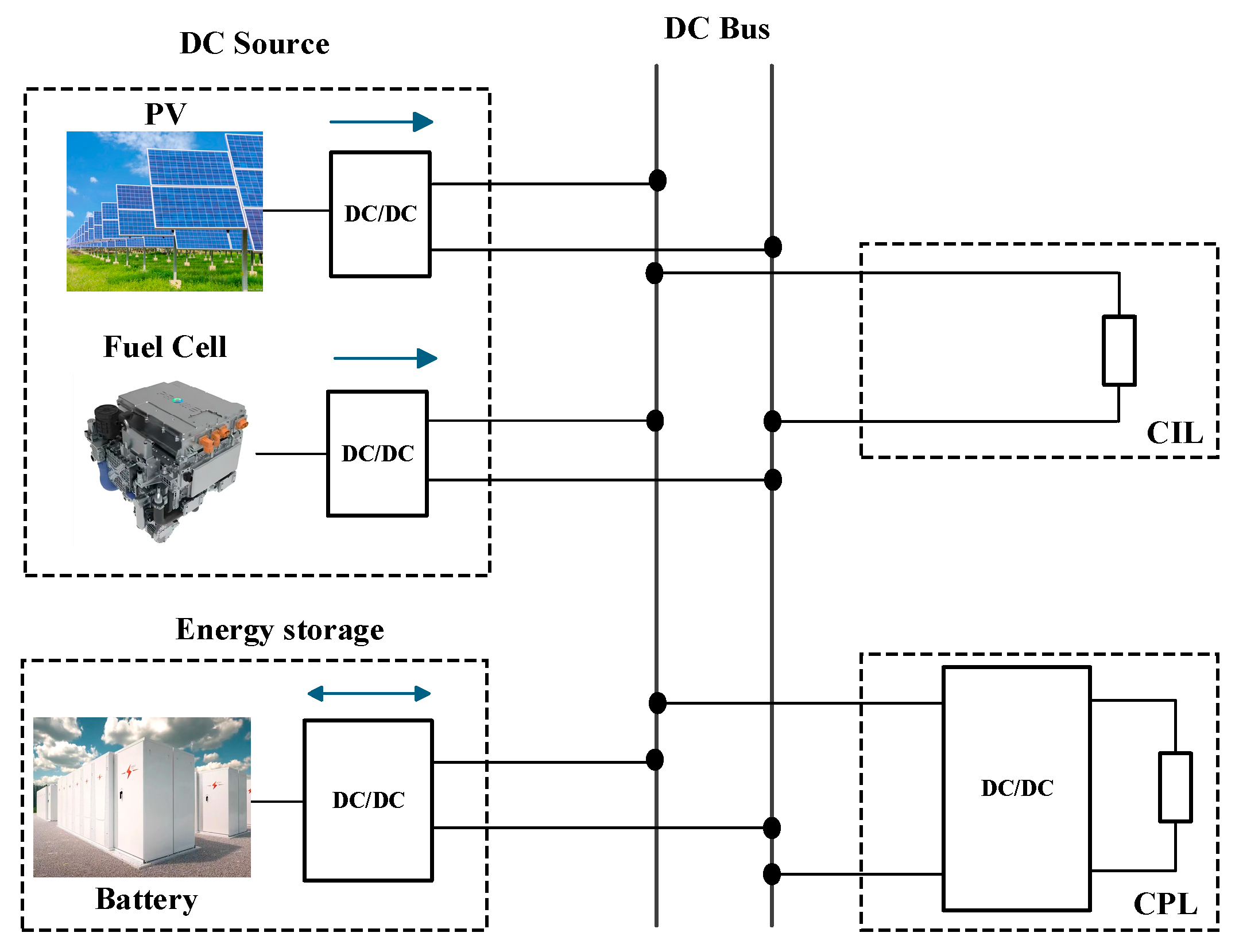
From a system architecture perspective, the DC/DC converter serves as the central power conversion unit within DC microgrids, and is widely deployed at various energy interfaces and load terminals. Its control performance is crucial to the overall stability and operational efficiency of the system. As shown in Figure 1, distributed generation units and energy storage systems connect to the DC bus via a front-end DC/DC converter, which commonly provides voltage step-up functionality. The regulated bus voltage then supplies power to the loads. Conversely, the back-end DC/DC converter commonly operates under closed-loop control to maintain a constant output voltage or current. When the load resistance remains constant, this operational mode yields a constant output power, effectively characterizing the back-end converter as a CPL [2,3]. The CPL exhibits negative impedance characteristics, which can undermine the system’s equivalent damping and compromise the dynamic stability of the DC microgrid [4,5,6].
To mitigate the stability challenge posed by the negative impedance characteristics of CPL, various stabilization approaches have been developed. These methods fall into three main categories, namely passive damping, active damping, and nonlinear control. Passive damping augments system damping through the addition of physical components such as resistors, capacitors [7,8], or LC filters [9], typically connected in series or parallel with filter elements to alleviate resonance peaks. While this method benefits from simple implementation and directly improves stability, it introduces notable drawbacks, including energy losses, increased system volume, and higher hardware costs. The active damping method synthesizes virtual impedances (e.g., virtual resistors or capacitors) through control algorithms, effectively enhancing system damping without adding physical components [10,11]. While this approach eliminates associated power losses, its effectiveness against the negative damping effect of a CPL presents a challenge, as this effect intensifies with increasing CPL power. Consequently, the active damping must be synchronously strengthened to maintain stability margins. Fixed-parameter schemes have difficulty adapting to this demand across wide operating ranges, and excessive damping can unduly slow down the system’s dynamic response [12]. To address large-signal stability challenges, researchers have begun integrating the concept of virtual impedance with nonlinear control theory. For instance, Reference [13] proposes an adaptive virtual impedance strategy, aiming to expand the stability region by dynamically adjusting damping parameters. Although this approach shows promising potential, it often relies on accurate system models and involves complex controller parameter tuning, posing challenges for ensuring global stability in practical applications. Some scholars have also applied Active Disturbance Rejection Control (ADRC) to DC/DC converters in DC microgrids, and the results show that its performance is superior to that of traditional Proportional-Integral (PI) controllers [14,15]. Furthermore, although nonlinear control methods demonstrate considerable promise in managing large disturbances, they often face two critical limitations: inadequate adaptability of control parameters and excessive sensitivity to model inaccuracies.
The LADRC presents a robust alternative by employing the LESO to estimate and compensate for the total system disturbance in real-time. This active estimation significantly reduces dependency on an accurate system model [16]. LADRC has demonstrated superior disturbance rejection capabilities in power electronics control. However, existing studies predominantly focus on systems with resistive loads or under simplified operating conditions [17,18]. Consequently, the application of LADRC in DC microgrids featuring complex hybrid loads, such as CPL, remains insufficiently explored. Key challenges, including the design of LESO parameters to balance fast dynamic response with strong robustness under the negative impedance effect of CPL, require further in-depth investigation.
In summary, the LADRC offers a robust solution to the stability issues posed by CPL and operational uncertainties in power electronic systems. Its core mechanism involves real-time estimation and cancellation of the total disturbance including the negative impedance effect of CPL via the LESO. This capability enables the LADRC to mitigate system oscillations and prevent voltage collapse under sudden load changes or parameter perturbations, substantially improving power supply reliability. Grounded in this framework, the present study formulates, implements, and validates a discrete LADRC-based control strategy for a Boost converter serving mixed loads. The work provides a comprehensive evaluation encompassing discrete-time implementation, formal stability proof, and experimental verification, confirming the controller’s capability for rapid dynamic response in large-signal stability scenarios.

2. System Modelling and Impedance Characteristic Analysis

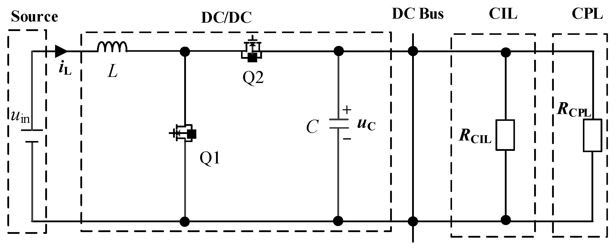
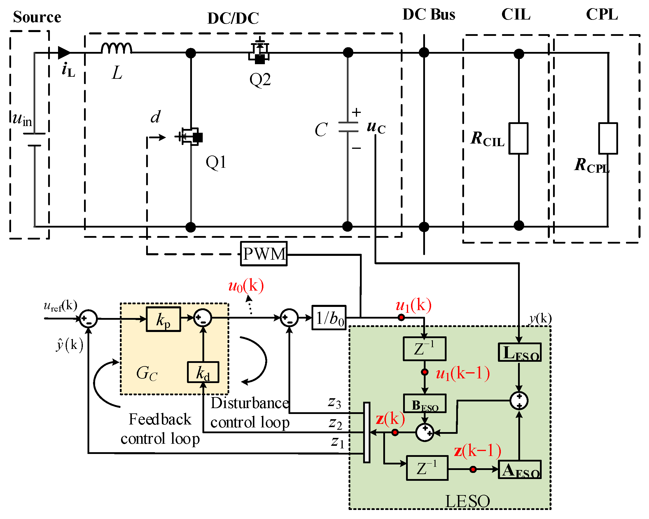
The typical DC microgrid system (Figure 1) is simplified as follows: distributed power sources are equivalent to ideal voltage sources, the closed-loop controlled back-end DC/DC converter is modeled as a CPL, and the DC bus load consists of parallel CPLs and constant impedance loads (CILs). The front-end DC/DC converter serves as the energy interaction unit between distributed sources and the DC bus, with its simplified equivalent circuit shown in Figure 2.
The key parameters illustrated in Figure 2 include the inductance (L) and capacitance (C) associated with the DC/DC converters. Q1 and Q2 represent the switching transistors. The equivalent resistances of the CIL and CPL, denoted as RCIL and RCPL, respectively, are included in the state-space averaging model as follows:
L d i L d t = u in ( 1 d ) u C C d u C d t = 1 d i L u C R CIL P CPL u C
where i L and u C are the average value of instantaneous inductor current and capacitor voltage, u i n stands for the voltage provided by the power source, and d refers to the duty ratio of the switching device.
The small-signal model of the controlled object can be derived as
L d i ^ L d t = ( 1 D ) u ^ C + U C d ^ C d u ^ C d t = 1 D i ^ L I L d ^ 1 R CIL P CPL U C 2 u ^ C
where the steady-state values of the duty ratio, inductor current, and output voltage correspond to D, IL and Uc, respectively, and the symbols d ^ , i ^ L and u ^ C signify the small-signal perturbations of these variables around the steady-state operating point.
The system transfer function, obtained via the Laplace transform of (2), is given by
u ^ C s d ^ s = U C 1 D I L L s L C s 2 + s L 1 R CIL P CPL U C 2 + 1 D 2
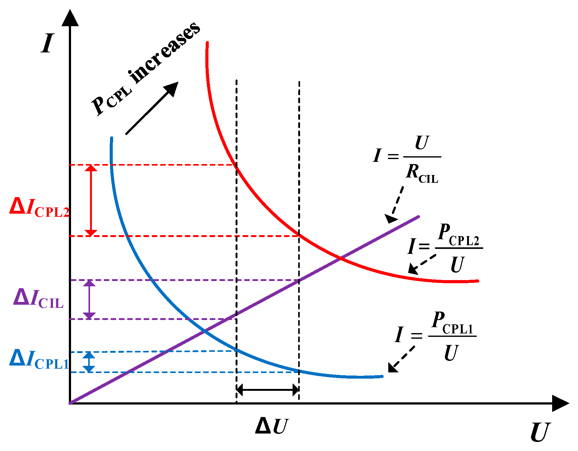
The electrical behaviors of the CIL and CPL, represented by their current-voltage (I-U) curves, are illustrated in Figure 3. When the CIL and CPL are connected in parallel to form a hybrid load, the incremental admittance of the load can be expressed as
Y eq = Y CIL + Y CPL = Δ I CIL Δ U CIL + Δ I CPL Δ U CPL = Δ I CIL Δ U + Δ I CPL Δ U
As can be seen from Figure 3, the CIL exhibits positive incremental admittance, i.e., Y CIL > 0 ; and the CPL shows negative incremental admittance, i.e., Y CPL < 0 . As the power of CPL increases (from PCPL1 to PCPL2), the incremental admittance of the hybrid load Y eq will become progressively smaller and may even turn from positive to negative.
Based on the U-I relationship of the load as shown in Figure 3, the incremental admittance Y eq in steady state can be further derived by differentiation as
Y eq = Y CIL + Y CPL = Δ I CIL Δ U CIL + Δ I CPL Δ U CPL = Δ I Δ U = 1 R CIL P CPL U C 2
Meanwhile, according to (3), it can be known that the damping ratio ζ of the controlled plant is closely related to the incremental admittance Y eq , i.e.,
ζ = Y eq 2 L C 1 1 D
The above analysis indicates that when only the CPL is connected, or when a hybrid load is connected but the power of CPL is relatively large (as shown by the red curve in Figure 3), the negative incremental admittance effect of the CPL becomes dominant. Consequently, the controlled plant exhibits negative damping characteristics ( ζ < 0 ) and negative incremental admittance ( Y eq < 0 ). In such a case, if a hybrid load disturbance causes an increase in the bus voltage Uc ( Δ U > 0 ) then the output current will decrease significantly ( Δ I < 0 ). This drop in current further increases Uc, thereby forming a positive feedback loop which ultimately leads to system instability.

3. Control Design of the DC/DC Converter in DC Microgrids Based on the LADRC

3.1. Basic Principles of LADRC

The LADRC method utilizes a LESO to actively estimate and compensate for the total disturbance affecting the system in real time, without relying on an accurate mathematical model. For an nth-order plant, its core framework is as follows:
y n = f   t ,   y ,     y ˙ ,   ,     y n 1 , u , ω + b 0 u
where y denotes the plant output and u represents the control input, b0 is the control gain, and f   is the total disturbance term.
To estimate the total disturbance, an extended state equation is introduced as
x ˙ = A x + B u + E h y = C x x = x 1     x 2 x n     x n + 1 T
where h = f ˙   denotes the change rate of the total disturbance, and x is the state vector that includes the extended state of x n + 1 = f , A, B, C, and E are coefficient matrices [19].
To achieve real-time tracking of both system states and the total disturbance, a LESO is utilized which is described by
z ˙ = A z + B u + L y y ^ y ^ = C z
where the state observation vector is z = z 1         z 2 z n         z n + 1 T , and L = β 1         β 2           β n         β n + 1 T denotes the observer gain. The system response is represented by y ^ , which is the observed output value. At steady state, z x .
To achieve active disturbance compensation for the plant, the observed value zn+1 is integrated into the control input as follows:
u = z n + 1 + u 0 b 0
Substituting (11) into (7), the differential equation form can be transformed into
y n = f t ,   y ,   y ˙ ,   ,   y n 1 ,   u ,   ω + b 0 z n + 1 + u 0 b 0 u 0
In this context, u0 represents the output of the external controller. In the design of the external controller, a linear form is typically adopted, expressed as
u 0 = k p r z 1 k d 1 z 2 k d 2 z 3 k d n 1 z n
where r denotes the reference value of the plant output.
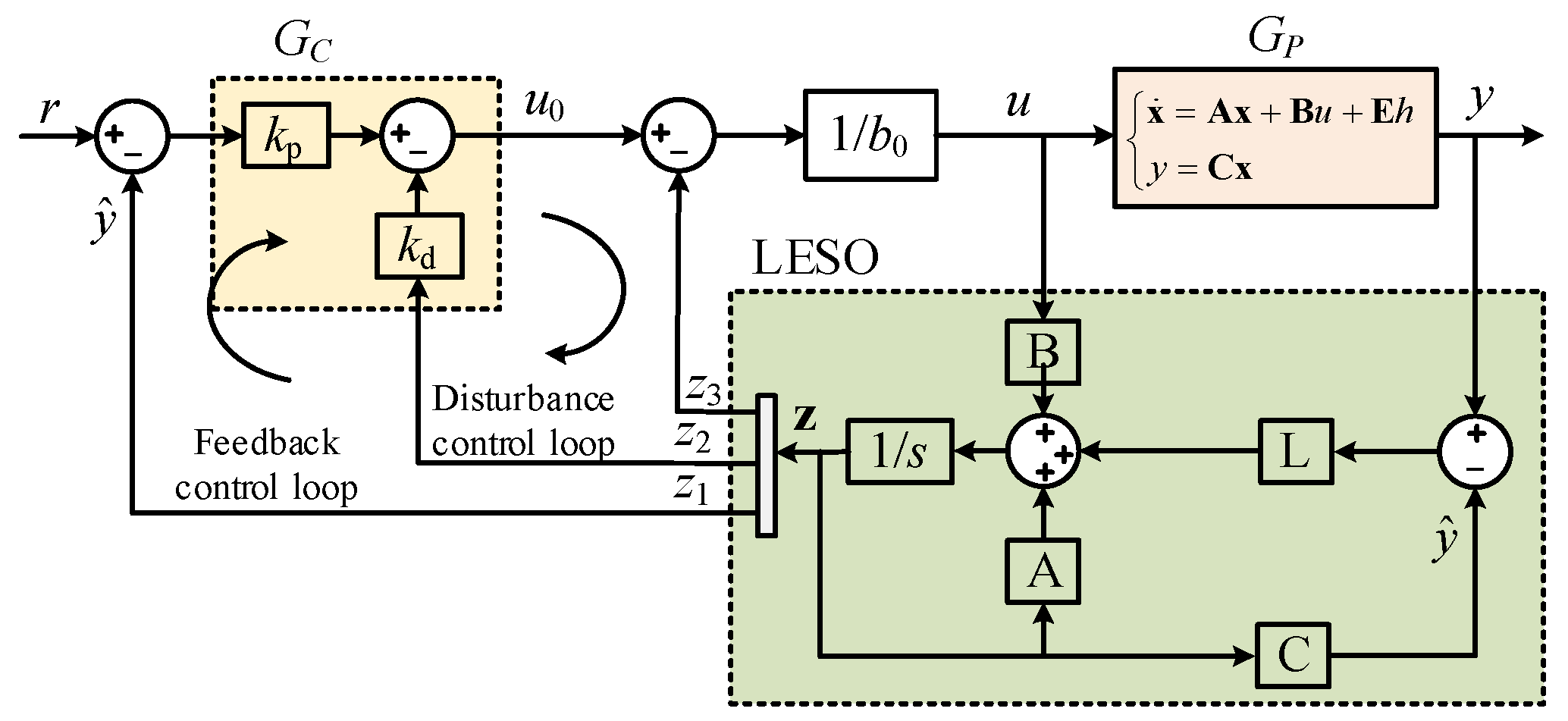
For the second-order system with n = 2, the external controller is designed as a proportional-derivative (PD) type, and the system control diagram is shown in Figure 4. The expressions for u0 and the closed-loop system transfer function G(s) are as follows
u 0 = k p r z 1 k d z 2 G s = k p / s 2 + k d s + k p
In summary, the LADRC strategy can be summarized as follows: unknown external disturbances and the internal dynamic characteristics of the system are collectively treated as a total disturbance term. A LESO is employed to estimate both the system state variables and this lumped disturbance in real time, while an active compensation mechanism is applied to eliminate its effects. In a DC microgrid, issues such as the negative damping characteristics introduced by constant power loads, as well as parameter disturbances in the main circuit inductors and capacitors, can all be incorporated into the total disturbance category for unified suppression.

3.2. Controller Strategy Design

To achieve robust operation of the Boost converter under hybrid load (CPL + CIL) conditions, a control architecture based on LADRC is proposed, as illustrated in Figure 5. To address the negative damping effect induced by the constant power load and the uncertainties in power circuit parameters, a LESO is utilized for real-time estimation, while an embedded disturbance control loop with an outer controller (GC) actively compensates for these effects. This disturbance control loop works in synergy with the feedback control loop to jointly generate PWM pulse drive signals, ultimately enabling precise control of the Boost converter.
For the overall system, the control objective is to ensure that the system output volt-age uC accurately tracks the reference voltage uref. Based on (1), it can be expressed as a second-order nonlinear system with the duty cycle d as the input, as follows:
u ¨ C = 1 C 1 L u in 1 d ( 1 d ) 2 u C i L d ˙ 1 R u ˙ C + P CPL u C 2 u ˙ C
Linearization at the steady-state operating point (uC0, iL0, d0)
b 0 = u ¨ C d = 1 C u in L + 2 1 d 0 u C 0 L
According to 1 d 0 u C 0 = u i n , then
b 0 = 1 C u in L + 2 u in L = u in L C
Construct a second-order dynamic model following the form of (7),
u ¨ C = b 0 d + f
The total disturbance f(⋅) is defined as
f = Δ f model + f CPL + f external
where fCPL represents the nonlinear term introduced by P CPL C u C 2 u ˙ C , Δ f model represents the uncertainty of model parameters, and fexternal signifies external disturbances.
The f(⋅) is extended as a new system state, that is, by defining the extended state x 3 = f . Let x 1 = u C and x 2 = u ˙ C . The original system is then transformed into a linear system as
x ˙ 1 = x 2 x ˙ 2 = x 3 + b 0 d x ˙ 3 = h
where h = f ˙ is bounded.
For this extended system, and in combination with (9), the LESO is designed as
z ˙ = A z + B d + L u C y ^ y ^ = C z
where the state observation vector is z = z 1   z 2   z 3 T , and L = β 1   β 2   β 3   T denotes the observer gain. At steady state, z x .
According to the ω0-Optimization tuning principle [20,21], combined with the pole configuration concept, the eigenvalues of the LESO can be tuned to −ω0, as follows
β 1 = 3 ω 0   , β 2 = 3 ω 0 2 , β 3 = ω 0 3
The bandwidth of the LESO is characterized by the parameter ω0. When designing L, the key principle is to keep the observer poles away from the pole distribution region of the closed-loop system, which is the core prerequisite for ensuring that the observer convergence speed is better than the system response. Normally, if the bandwidth of the closed-loop system is ωc, a commonly adopted tuning rule is to set ω0 = (3~10)ωc [22].
Based on the estimation results from the LESO, the control law is designed as follows:
u 1 = u 0 z 3 b 0
where u1 essentially represents the duty cycle d.

3.3. Discretization Process

For the extended system, the discretized LESO can be expressed as [19]
z k = A ESO z k 1 + B ESO u 1 k 1 + L ESO y k
where AESO, BESO, and CESO are defined as
A ESO = A d L c C d A d B ESO = B d L c C d B d L ESO = L c
For the extended system (n = 2), the values of Ad, Bd, and LC are
A d = 1           T s         T s 2 2 0           1           T s 0           0           1 ,     B d = b 0 T s 2 2 b 0 T s         0 ,     L c = 1 β 3 3 1 β 2 1 + β 2 T s         1 β 3 / T s 2
The output of the external controller GC can be discretized and expressed as
u 0 ( k ) = k p u ref ( k ) z 1 k d z 2
where uref represents the reference voltage.
Then the discretized control law can be derived as
u 1 k = k p u ref k k p       k d   1 z k b 0
According to (13), the control bandwidth ω c , damping ratio ξ , and response time t d of the LADRC are, respectively, given by
ω c =   k p ,       ξ = k d / 2 ω c ,           t d = 4 / ξ ω c
The damping ratio is set to 0.7. Furthermore, in order to avoid oscillation while enhancing the bandwidth of the closed-loop system, the t d is set to 20 ms. Finally, The values of ω c and ω 0 are set to
ω c = 300   rad / s ,             ω 0 = 3 ω c

4. Stability Analysis

4.1. Convergence of Disturbance Estimation Error

Based on the properties of the LESO, the system state observation vector z = z 1   z 2   z 3 T can rapidly and accurately track the system state vector x = x 1   x 2   x 3 T , and the disturbance rate h = f ˙ is bounded. Therefore, the following holds
max sup h ( t ) K , K R +
Define the estimation error matrix as
e = e 1     e 2     e 3 T = x 1 z 1     x 2 z 2     x 3 z 3 T
The error dynamic equation is
e ˙ = A e e + E h
where
A e = β 1 1 0 β 2 0 1 β 3 0 0 ,   E = 0         0         1 T
According to the observer gain designed in (21), the characteristic polynomial of matrix Ae satisfies
det s   I A e   = ( s + ω 0 ) 3
Since all poles are located at ω 0 , the matrix Ae is Hurwitz and the corresponding linear system is asymptotically stable [23].
In summary, by setting the observer bandwidth ω 0 sufficiently large, the bounded error term caused by the disturbance variation rate can be reduced, ultimately enabling the LESO to rapidly and accurately track the system state variables while achieving precise estimation of the total disturbance f , that is z 3 f .

4.2. Closed-Loop System Stability

Substituting the control law (22) into (17), then
u ¨ C = b 0 u 0 z 3 b 0 + f = u 0 z 3 + f
With accurate LESO estimation, z 3 f , then
u ¨ C u 0
From (36), through the real-time estimation and active compensation of disturbances by LADRC, the original second-order system, which contains nonlinearities and uncertainties, is effectively converted into a standard double-integrator form. Furthermore, assuming the LESO provides accurate state estimation ( z 1 u C ,     z 2 u ˙ C ). Then the closed-loop system equation is
u ¨ C + k d u ˙ C + k p u C = k p u ref
Correspondingly, the characteristic equation can be derived as
s 2 + k d s + k p = 0
By setting k p = ω c 2 ,       k d = 2 ω c ξ , all system poles can be placed in the left-half plane, thereby ensuring that the closed-loop system is asymptotically stable.
In summary, the fundamental mechanism by which LADRC overcomes negative-damping instability resides in the capability of its LESO. The LESO actively estimates and compensates in real-time for the total disturbance, which encompasses the negative impedance characteristics of CPL, model uncertainties, and external disturbances. This action effectively linearizes the system. Consequently, it prevents the rightward shift of system poles induced by negative damping, thereby enhancing the system’s stability margin and its robustness under varying operating conditions.

4.3. Analysis of Robustness to Parameter Perturbations

The nominal gain of the model is expressed by (16). When the actual inductance and capacitance values are subject to disturbances, the disturbance ratio is defined as
η L = L 1 L , η C = C 1 C
where the inductance and capacitance values of the power circuit, following parameter disturbances, are denoted as L1 and C1, respectively.
The actual control gain b1 is
b 1 = u in L 1 C 1 = u in η L η C L C
Based on (17), the corrected model with the perturbations is
u ¨ C = b 1 d + f
Then the influence of parameter deviation is explicitly separated
u ¨ C = b 0 d + f + 1 η L η C 1 b 0 d
The additional disturbance caused by parameter perturbations can be expressed as
f param = 1 η L η C 1 b 0 d
The extended state vector, which includes the total disturbance, is given by
f total = f + f param = Δ f model + f CPL + f external + f param
In summary, any variations in inductance and capacitance can be attributed to dynamic errors caused by deviations in control gain and thus be incorporated into the total disturbance. For any bounded function f(·), the LESO is capable of observing and compensating for it in real time.

5. Simulation and Experimental Results

5.1. Simulation Results

The performance and robustness of the proposed control strategy were assessed through simulations conducted on the MATLAB2020/Simulink platform based on the equivalent circuit shown in Figure 2, with the relevant parameters detailed in Table 1.
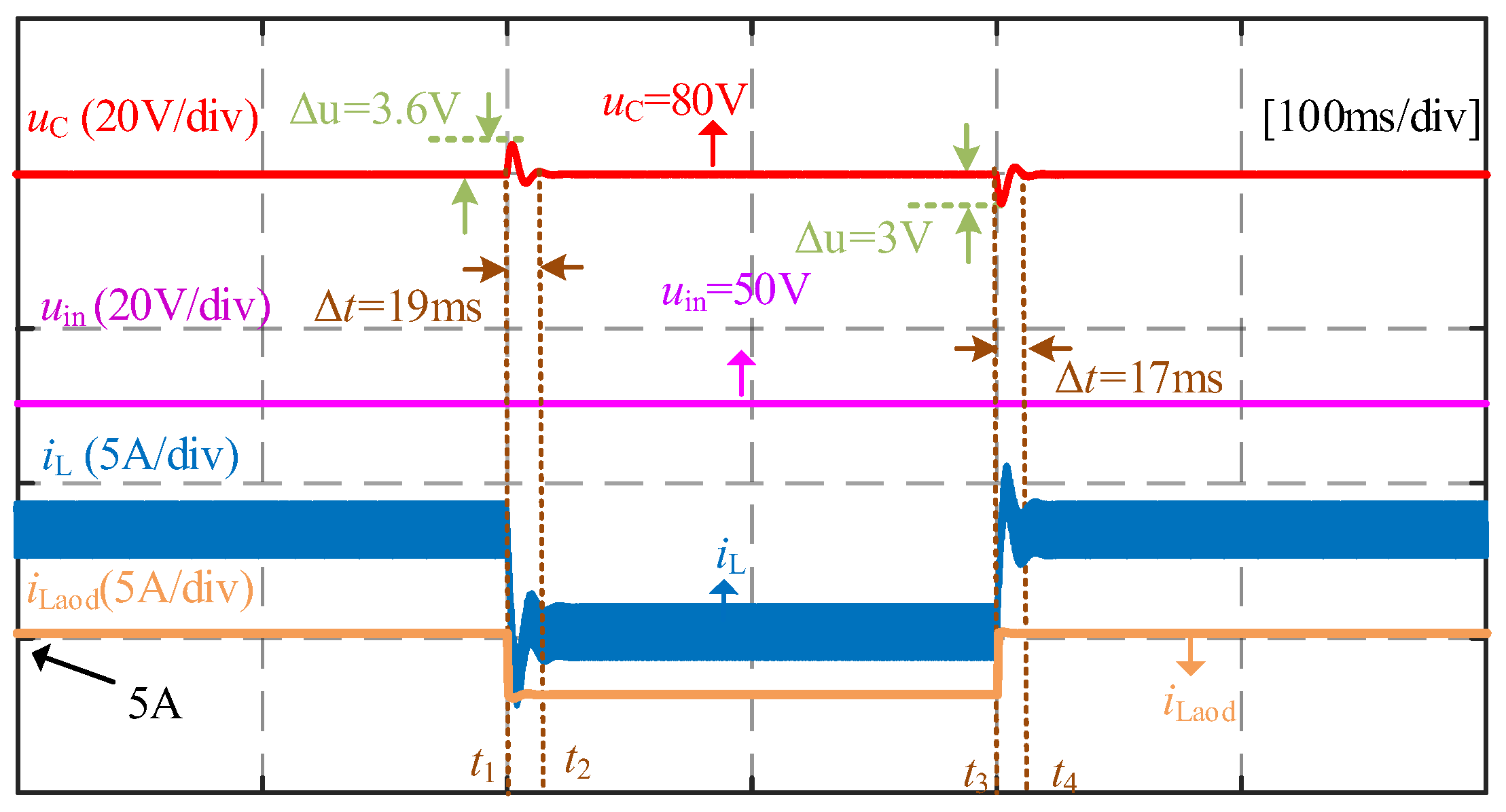
Operating Condition 1: CIL disturbance with negative-damping hybrid loads.
A stepwise disturbance test was performed to evaluate the system response under a CIL variation, with the results presented in Figure 6. The test began with a 40 Ω CIL and a 250 W CPL connected to the DC bus. The CIL was shed at t1 and subsequently reconnected at t3. The system demonstrated consistent stability across the various applied load changes. Notably, each CIL shed/load event induced a minor voltage deviation of approximately 3.6 V and was recovered within 19 ms, demonstrating the controller’s effectiveness in managing load disturbances.
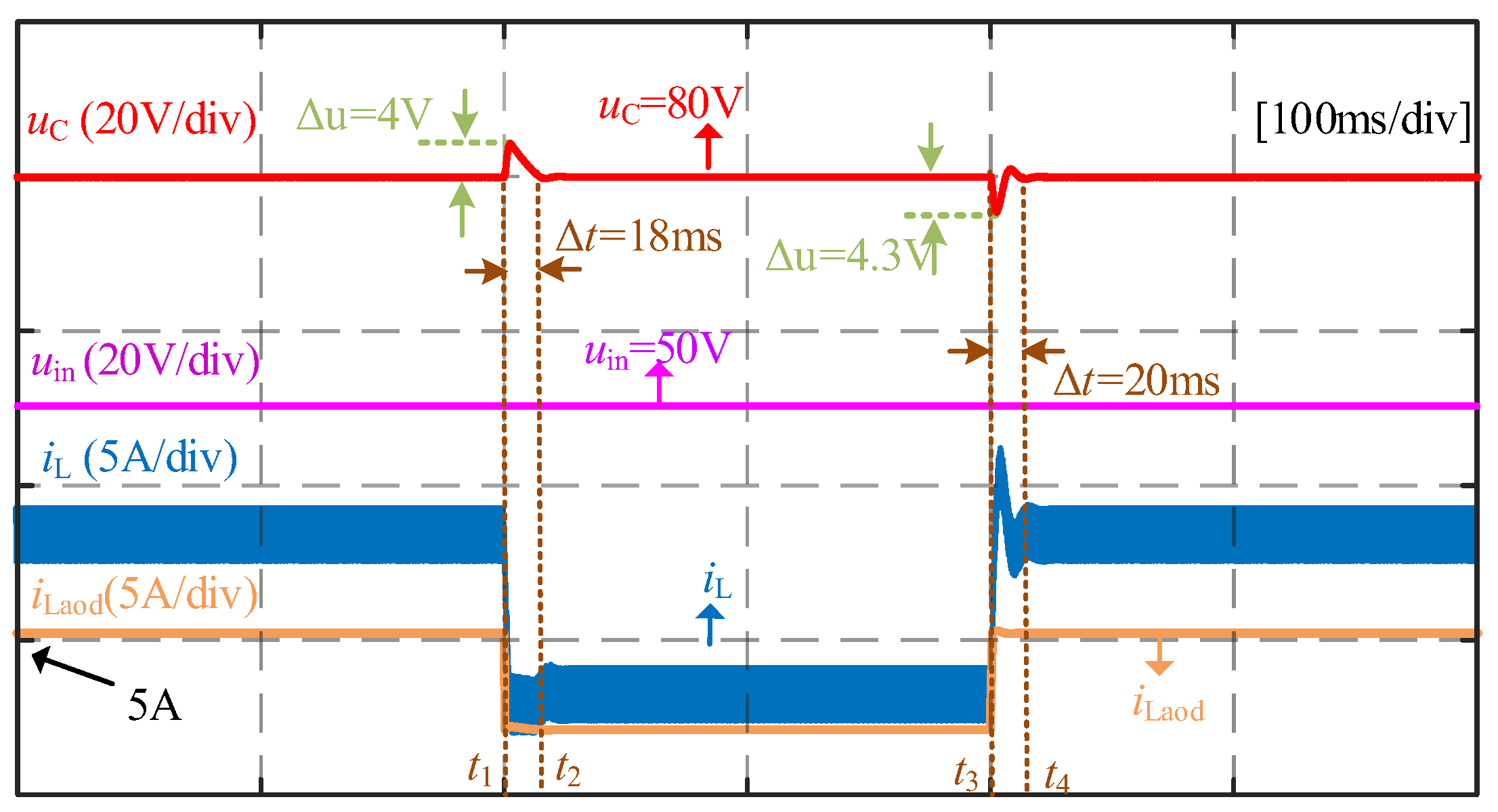
Operating Condition 2: CPL disturbance with negative-damping hybrid loads.
Initially, 40 Ω CIL and 250 W CPL were connected to the DC bus. The CPL was disconnected at t1 and reconnected CPL at t3. As illustrated in Figure 7, during the disconnection process, the DC bus voltage exhibits a deviation of ~4 V with a recovery time of 18 ms. Conversely, during the reconnection process, the voltage deviation is ~4.3 V with a recovery time of about 20 ms. Throughout the entire transient process, the DC bus voltage remains stable, with no sustained oscillations or overshoots exceeding the allowable range.
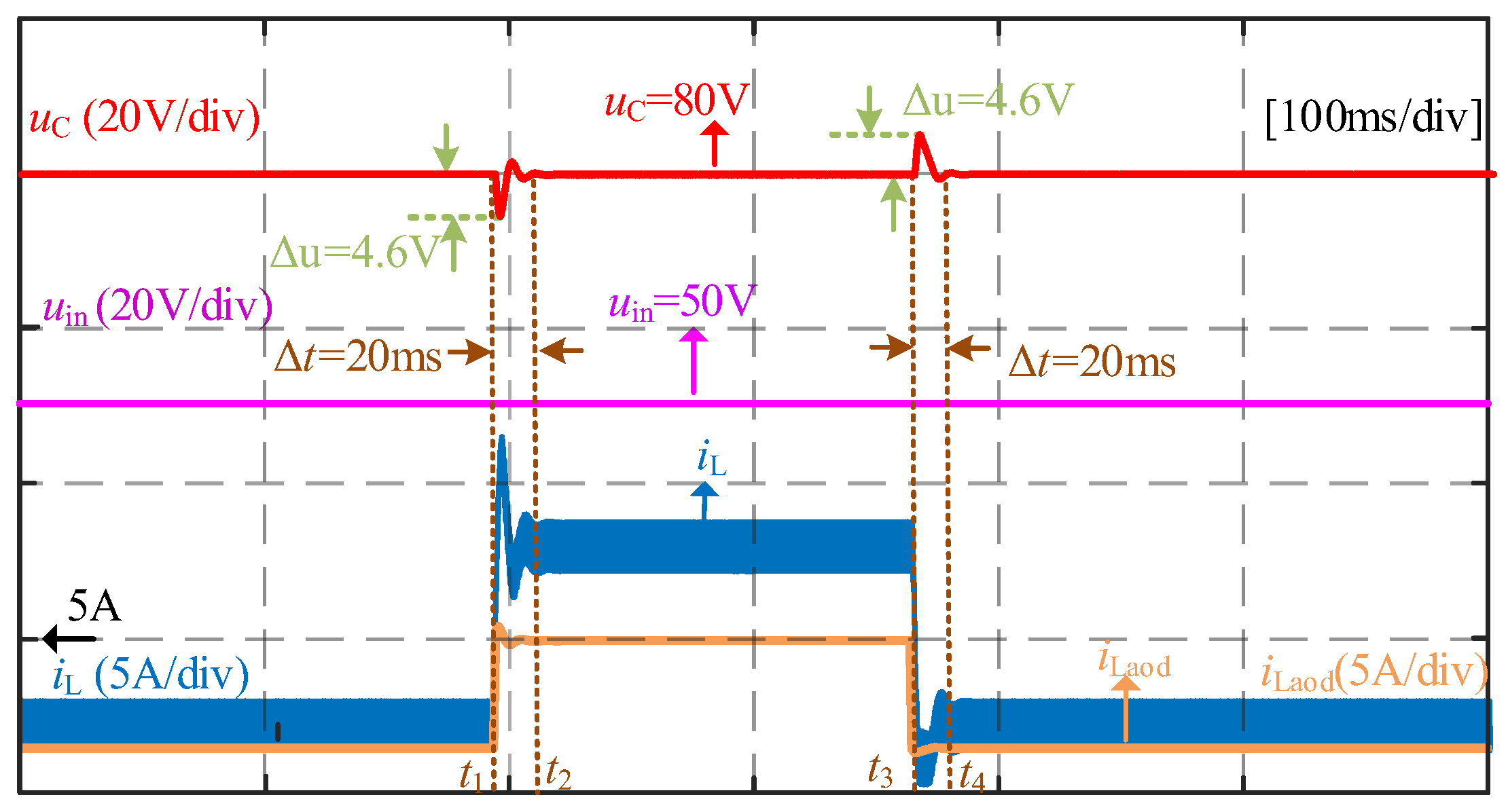
Operating Condition 3: CPL disturbance.
The system was initially configured with only a 100 W CPL connected to the DC bus, thereby also operating in a negative-damping state. At t1, the CPL was increased to 400 W (heavy-load state). At t3, the CPL was reduced back to 100 W (light-load state). Figure 8 presents the corresponding dynamic responses of the uC, uin, and iL during these load transitions, the DC bus voltage exhibits a peak deviation of approximately 4.6 V with a recovery time of 20 ms. Throughout the entire large-signal disturbance process, the system maintains stable operation without divergent oscillations or voltage collapse.
Operating Condition 4: power circuit parameter perturbation.
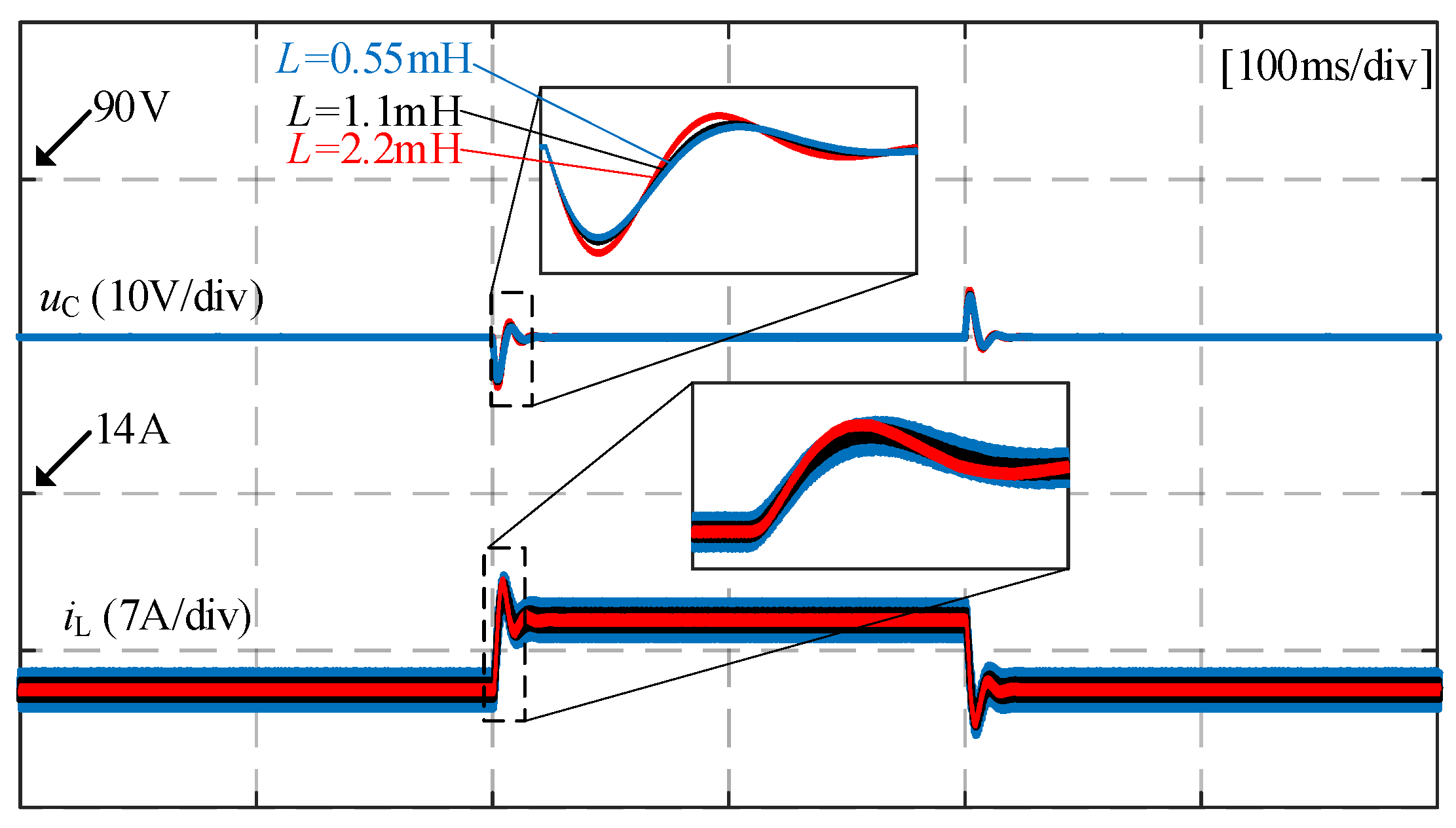
Under the initial conditions, a 40 Ω CIL and a 250 W CPL were connected to the DC bus. At t1, the CPL was stepped up to 500 W, and at t3, it was stepped down to 100 W. Figure 9 shows the dynamic response waveforms of the output voltage uC and inductor current iL for inductance values of 0.55 mH, 1.1 mH, and 2.2 mH. It can be seen that under the step disturbance of the CPL, the DC bus voltage remains stable regardless of the variation in inductance. These results demonstrate that the proposed control strategy exhibits excellent robustness against perturbations in the power circuit parameters of the system.

5.2. Experimental Results

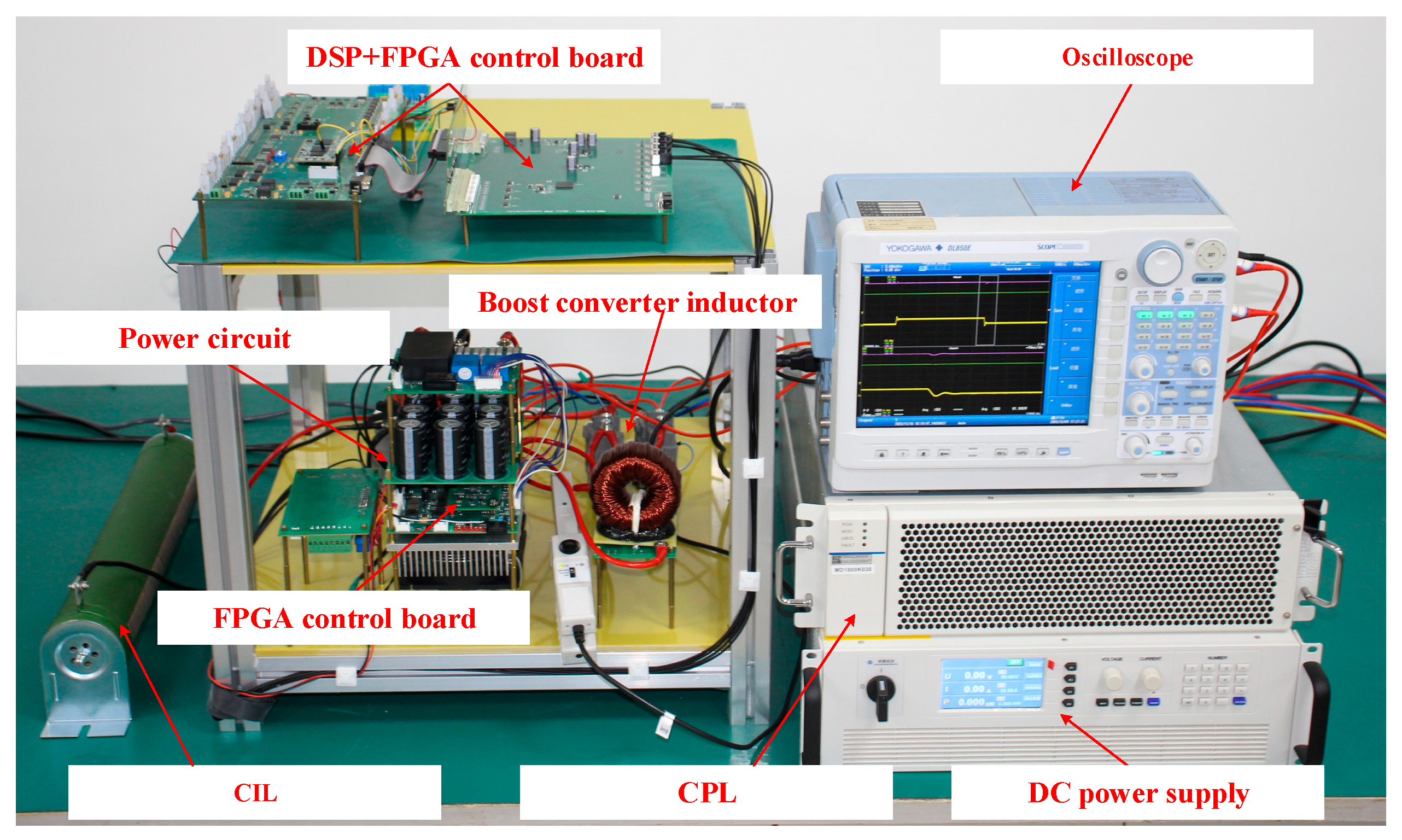
The proposed strategy was validated on a dedicated low-voltage (80 V) DC microgrid test platform. As illustrated in Figure 10, the platform configuration comprises a DC power supply, a Boost converter, a mixed load, and a control board. The control board is built around a DSP (TMS320C6748) and an FPGA (EG4S20BG256): the DSP implements the control algorithm, whereas the FPGA handles data acquisition and pulse-width modulation (PWM) signal generation. For load emulation, a resistive load simulates the CIL, and an electronic load operating in constant power mode represents the CPL. Key parameters of the experimental setup are summarized in Table 1.
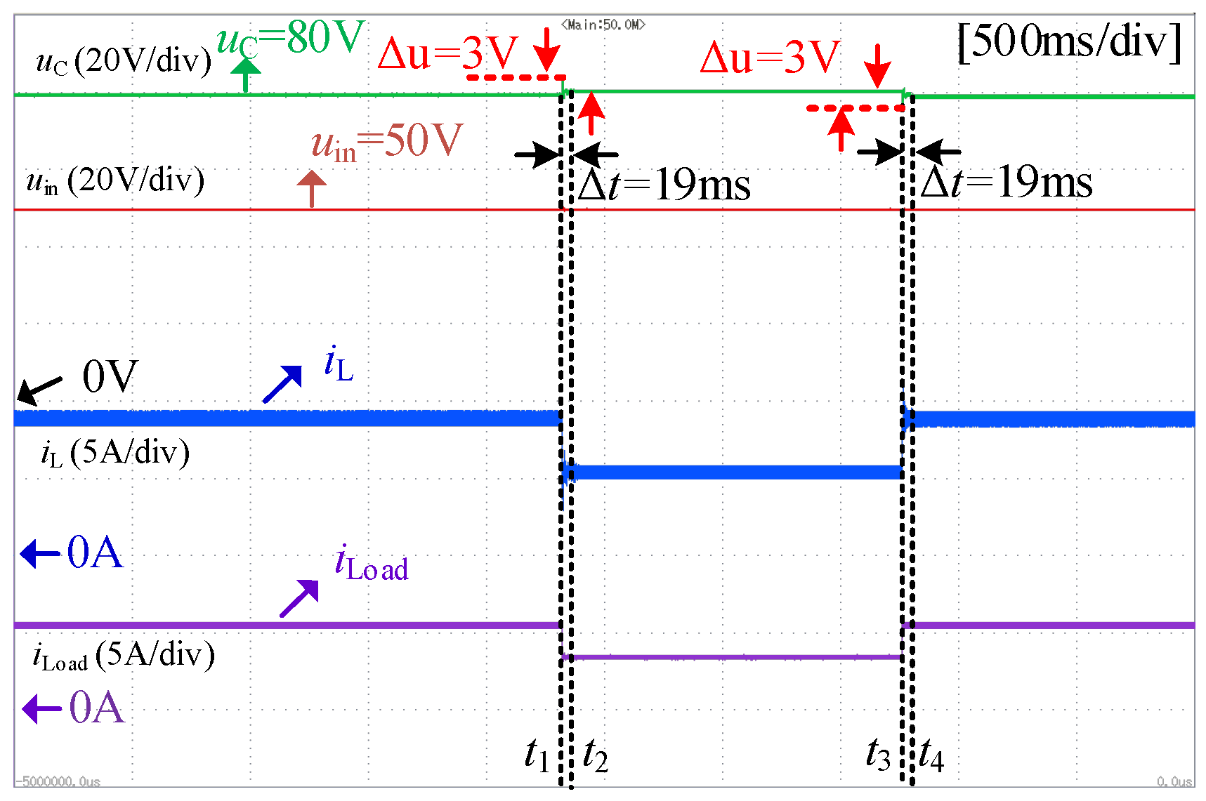
Experimental verification was conducted for Operating Condition 1. When the system was operating stably, a 40 Ω CIL and a 250 W CPL were connected to the DC bus. The CIL was disconnected at t1 and reconnected at t3. Figure 11 illustrates the dynamic response of the DC microgrid during the CIL switching transients. As clearly observed, throughout the disconnection and reconnection processes, the output voltage is maintained around the rated 80 V, with a peak deviation of approximately 3 V and a settling time of about 19 ms. No sustained oscillations or excessive deviations are observed, confirming the stable operation of the system under this test condition.
Experimental verification was carried out for Operating Condition 2, with a focus on the CPL disconnection and reconnection processes under a hybrid load. Initially, the system was operating stably with a 40 Ω CIL and a 250 W CPL connected to the DC bus. The CPL was disconnected at t1 and reconnected at t3. Figure 12 illustrates the corresponding dynamic response of the DC microgrid during these switching transients. As shown, both CPL disconnection and reconnection produce a transient peak voltage deviation of approximately 3.2 V. The output recovers to the rated 80 V within a settling time of about 20 ms in each case. Throughout the process, voltage stability is preserved without sustained oscillations or excessive overshoot.
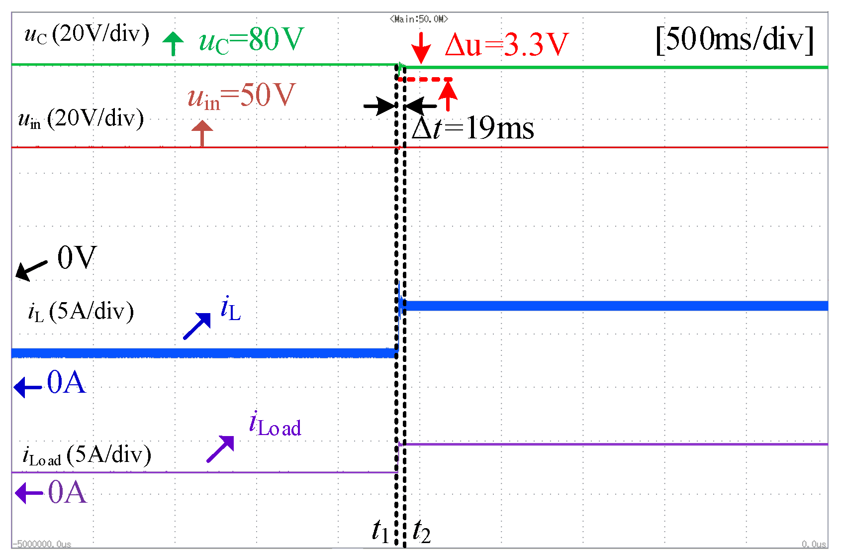
The experimental results for Operating Condition 3 are given in Figure 13. Starting with only a 150 W CPL, the load was stepped up to 350 W at t1, driving the system into a heavy-load state. Figure 13 shows that following this step change, both uC and iL settle to a new steady-state within about 19 ms, with the voltage exhibiting a transient dip of roughly 3.3 V. Throughout the large-signal disturbance, the DC bus voltage remains regulated around the rated 80 V, confirming the strategy’s fast recovery and excellent large-signal robustness.
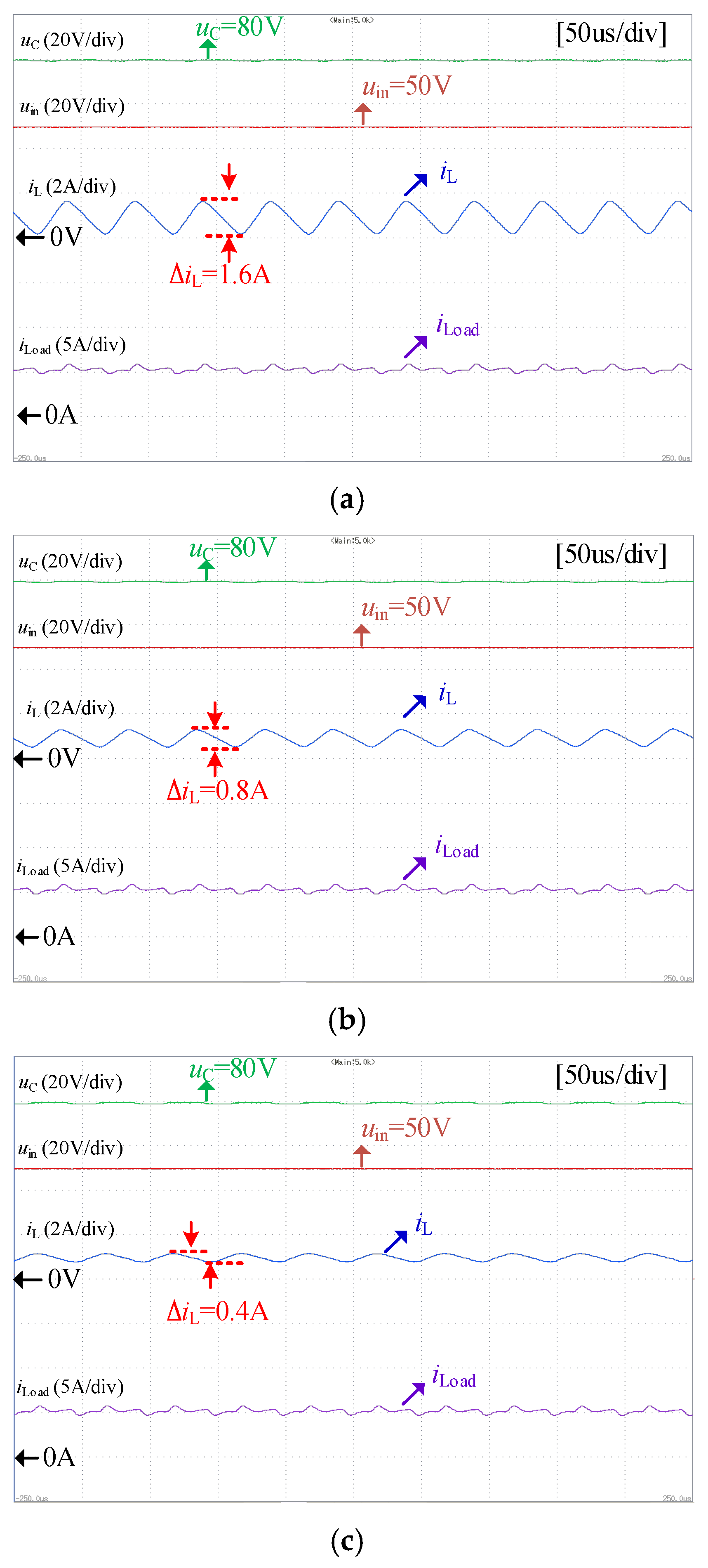
The steady-state waveforms obtained from the parameter perturbation experiments are presented in Figure 14. The tests were conducted under the following conditions: an input voltage of uin = 50 V, with the hybrid load comprising a 40 Ω CIL and a 250 W CPL, with the inductor parameter set to 0.55 mH, 1.1 mH, and 2.2 mH, respectively. The experimental results are as follows: in Figure 14a, with the inductor at 0.55 mH, the uC remains stable at 80 V and the inductor current ripple Δ i L is 1.6 A. In Figure 14b, with the inductor at the nominal value of 1.1 mH, the uC remains stable at 80 V and the Δ i L is approximately 0.8 A. In Figure 14c, when the inductor is increased to 2.2 mH, the uC remains stable at 80 V and the Δ i L decreases to 0.4 A. The system maintains stability under all operating conditions, verifying the effectiveness of the proposed control algorithm in handling parameter variations.

6. Conclusions

To achieve voltage tracking and robust control for a Boost converter supplying hybrid loads over a wide operating range, this study carries out the following work. Firstly, an equivalent circuit model of a DC microgrid incorporating a constant power load is established. This model theoretically clarifies how the equivalent incremental admittance of the hybrid load affects the system damping. Subsequently, a control strategy is designed based on the LADRC framework. Its core mechanism lies in using a LESO to observe and actively compensate for the lumped total disturbance, which includes complex disturbances such as the nonlinear characteristics of the constant power load and parameter variations. This method linearizes the controlled plant, effectively mitigating the instability issues caused by negative damping and parameter perturbations. Finally, both simulation and experimental results demonstrate that the proposed strategy exhibits excellent control performance and robustness in handling load transients and parameter uncertainties.

Author Contributions

Conceptualization, H.D. and W.W.; Methodology, H.D. and W.W.; Software, S.L. and L.J.; Validation, H.D., W.W., Y.Z., S.L. and L.J.; Formal analysis, Y.Z.; Investigation, L.J.; Data curation, S.L. and L.J.; Writing—original draft, H.D. and S.L.; Writing—review & editing, H.D., W.W. and Y.Z.; Supervision, Y.Z.; Project administration, W.W. All authors have read and agreed to the published version of the manuscript.

Funding

This research was funded by the Natural Science Foundation of China, grant Nos. CSTB2022NSCQ-MSX1396, 2024-JCJQ-JJ-0290.

Data Availability Statement

The original contributions presented in this study are included in the article. Further inquiries can be directed to the corresponding author(s).

Conflicts of Interest

The authors declare no conflict of interest.

References

  1. Xu, L.; Guerrero, J.M.; Lashab, A.; Wei, B.; Bazmohammadi, N.; Vasquez, J.C.; Abusorrah, A. A review of DC shipboard microgrids part I: Power architectures, energy storage and power converters. IEEE Trans. Power Electron. 2022, 37, 5155–5172. [Google Scholar] [CrossRef]
  2. Li, X.; Zhang, X.; Jiang, W.; Wang, J.; Wang, P.; Wu, X. A novel assorted nonlinear stabilizer for DC–DC multilevel boost converter with constant power load in DC microgrid. IEEE Trans. Power Electron. 2020, 35, 11181–11192. [Google Scholar] [CrossRef]
  3. Xu, P.; Wen, H.; Bu, Q.; Dai, L.; Zhu, Y.; Khan, S.S.; Shi, H.; Zhou, J.; Ma, J.; Hu, Y.; et al. Large-signal stability for DAB converters feeding constant power load based on state trajectory analysis. IEEE Trans. Transp. Electrif. 2024, 11, 3244–3261. [Google Scholar] [CrossRef]
  4. Hassan, M.A.; Su, C.L.; Pou, J.; Sulligoi, G.; Almakhles, D.; Bosich, D.; Guerrero, J.M. DC shipboard microgrids with constant power loads: A review of advanced nonlinear control strategies and stabilization techniques. IEEE Trans. Smart Grid 2022, 13, 3422–3438. [Google Scholar] [CrossRef]
  5. Kapat, S.; Krein, P.T. A tutorial and review discussion of modulation, control and tuning of high-performance DC–DC converters based on small-signal and large-signal approaches. IEEE Open J. Power Electron. 2020, 1, 339–371. [Google Scholar] [CrossRef]
  6. Xu, Q.; Zhang, C.; Wen, C.; Wang, P. A novel composite nonlinear controller for stabilization of constant power load in DC microgrid. IEEE Trans. Smart Grid 2019, 10, 752–761. [Google Scholar] [CrossRef]
  7. Kwasinski, A.; Onwuchekwa, C.N. Dynamic behavior and stabilization of DC microgrids with instantaneous constant-power loads. IEEE Trans. Power Electron. 2011, 26, 822–834. [Google Scholar] [CrossRef]
  8. Riccobono, A.; Santi, E. Comprehensive review of stability criteria for DC power distribution systems. IEEE Trans. Ind. Appl. 2014, 50, 3525–3535. [Google Scholar] [CrossRef]
  9. Cespedes, M.; Xing, L.; Sun, J. Constant-power load system stabilization by passive damping. IEEE Trans. Power Electron. 2011, 26, 1832–1836. [Google Scholar] [CrossRef]
  10. Liu, Z.; Xing, L.; Fang, J.; Shu, Z.; Su, H. Distributed Secondary Control for DC Microgrids with Near-Infinite Constant Power Load Accommodation. IEEE Trans. Smart Grid 2025, 16, 4451–4462. [Google Scholar] [CrossRef]
  11. Zhang, X.; Ruan, X.; Zhong, Q.-C. Improving the stability of cascaded dc/dc converter systems via shaping the input impedance of the load converter with a parallel or series virtual impedance. IEEE Trans. Ind. Electron. 2015, 62, 7499–7512. [Google Scholar] [CrossRef]
  12. Lu, X.; Sun, K.; Guerrero, J.M.; Vasquez, J.C.; Huang, L.; Wang, J. Stability enhancement based on virtual impedance for DC microgrids with constant power loads. IEEE Trans. Smart Grid 2015, 6, 2770–2783. [Google Scholar] [CrossRef]
  13. Li, Y.; Shao, Z.; Tu, Q.; Liu, J.; Tu, Z.; Li, Y. An Adaptive Virtual Impedance Control Strategy Based on Power Synchronization Control. In Proceedings of the 2024 International Conference on HVDC (HVDC), Urumqi, China, 8–9 August 2024; pp. 906–911. [Google Scholar]
  14. Zhuo, S.; Gaillard, A.; Guo, L.; Xu, L.; Paire, D.; Gao, F. Active disturbance rejection voltage control of a floating interleaved DC-DC boost converter with switch fault consideration. IEEE Trans. Power Electron. 2019, 34, 12396–12406. [Google Scholar] [CrossRef]
  15. Jin, S.; Zhuo, S.; Huangfu, Y. Design of ADRC based on improved ESO for enhanced robustness of bidirectional DC/DC converters in DC microgrid. In Proceedings of the IECON 2023—49th Annual Conference of the IEEE Industrial Electronics Society, Singapore, 16–19 October 2023; pp. 1–6. [Google Scholar]
  16. Lin, P.; Wu, Z.; Fei, Z.; Sun, X.-M. A Generalized PID Interpretation for High-Order LADRC and Cascade LADRC for Servo Systems. IEEE Trans. Ind. Electron. 2022, 69, 5207–5214. [Google Scholar] [CrossRef]
  17. Li, M.; Meng, X. A Hybrid Energy Storage Converter Control Method Based on Dual-Loop LADRC. In Proceedings of the 2024 IEEE 7th International Conference on Information Systems and Computer Aided Education (ICISCAE), Dalian, China, 27–29 September 2024; pp. 776–782. [Google Scholar]
  18. Zhao, M.; Liu, J.; Li, L. Simulation of Bidirectional DC-DC Converter Based on Improved Linear Active Disturbance Rejection Control. In Proceedings of the 2024 IEEE China International Youth Conference on Electrical Engineering (CIYCEE), Wuhan, China, 6–8 November 2024; pp. 1–6. [Google Scholar]
  19. Wen, W.; Long, S.; Zhang, Y.; Zhang, Z.; Wang, L.; Deng, H.; Li, R. Linear active disturbance rejection control for dynamic power decoupling of modular multi-active-bridge converter. In Proceedings of the 2024 6th International Conference on Energy Systems and Electrical Power (ICESEP), Wuhan, China, 21–23 June 2024; pp. 1466–1471. [Google Scholar]
  20. Gao, Z. Scaling and bandwidth-parameterization based controller tuning. In Proceedings of the 2003 American Control Conference, Denver, CO, USA, 4–6 June 2003; pp. 4989–4996. [Google Scholar]
  21. Ahmad, S.; Ali, A. Unified disturbance-estimation-based control and equivalence with IMC and PID: Case study on a dc-dc boost converter. IEEE Trans. Ind. Electron. 2021, 68, 5122–5132. [Google Scholar] [CrossRef]
  22. He, T.; Wu, Z.; Li, D.; Wang, J. A tuning method of active disturbance rejection control for a class of high-order processes. IEEE Trans. Ind. Electron. 2020, 67, 3191–3201. [Google Scholar] [CrossRef]
  23. Luo, W.; Vazquez, S.; Liu, J.; Gordillo, F.; Franquelo, L.G.; Wu, L. Control system design of a three-phase active front end using a sliding-mode observer. IEEE Trans. Syst. Man Cybern. Syst. 2020, 52, 739–748. [Google Scholar] [CrossRef]
Figure 1. Typical structure of DC microgrids.
Energies 19 00697 g001
Figure 2. The equivalent circuit diagram of the system.
Energies 19 00697 g002
Figure 3. The current–voltage characteristics of the CIL and CPL.
Energies 19 00697 g003
Figure 4. Structure diagram of the LADRC.
Energies 19 00697 g004
Figure 5. Structure of the proposed controller.
Energies 19 00697 g005
Figure 6. Simulation results with CIL shedding/loading under negative-damping hybrid loads.
Energies 19 00697 g006
Figure 7. Simulation results with CPL shedding/loading under negative-damping hybrid loads.
Energies 19 00697 g007
Figure 8. Simulation results with CPL disturbance.
Energies 19 00697 g008
Figure 9. Simulation results with parameter perturbation of the power circuit.
Energies 19 00697 g009
Figure 10. The scaled-down microgrid experimental platform.
Energies 19 00697 g010
Figure 11. Experimental results with CIL shedding/loading under negative-damping hybrid loads.
Energies 19 00697 g011
Figure 12. Experimental results with CPL shedding/loading under negative-damping hybrid loads.
Energies 19 00697 g012
Figure 13. Experimental results with CPL disturbance.
Energies 19 00697 g013
Figure 14. Experimental results with different inductors: (a) 0.55 mH, (b) 1.1 mH, (c) 2.2 mH.
Energies 19 00697 g014
Table 1. Key parameters of the test platform.
VariableSymbolValue
Input voltageuin50 V
Converter inductorL1.1 mH
Converter capacitorC840 uF
Constant impedance loadR40 Ω
Switching frequencyfs20 kHz
DC bus voltageuC80 V
Constant power loadPCPL250 W
Disclaimer/Publisher’s Note: The statements, opinions and data contained in all publications are solely those of the individual author(s) and contributor(s) and not of MDPI and/or the editor(s). MDPI and/or the editor(s) disclaim responsibility for any injury to people or property resulting from any ideas, methods, instructions or products referred to in the content.