Review

Research on Key Technologies for Microwave Wireless Power Transfer Receivers

Institute of System Engineering Academy of Military Science, Beijing 102300, China
*
Author to whom correspondence should be addressed.
Energies 2026, 19(2), 438; https://doi.org/10.3390/en19020438
Submission received: 21 November 2025 / Revised: 19 December 2025 / Accepted: 29 December 2025 / Published: 16 January 2026
(This article belongs to the Special Issue Design, Modelling and Analysis for Wireless Power Transfer Systems)

Abstract

Microwave wireless power transfer (MWPT) technology has the advantages of long distance and high transmission efficiency; therefore, MWPT has many applications in aerospace, space solar power stations (SSPSs), and so on. The receiving and fixing subsystem is the core component for gathering and converting power and it is the main part of the system. If this step is both efficient and possible, the whole system will also be efficient and its success possible. This paper mainly introduces a systematic review of the key technologies, research status, and development trends of the receiving-end part in MWPT. High-performance rectifying devices are analyzed in detail, with the use of GaN Schottky barrier diodes (GaN SBDs), in addition to rectification circuits that have good rectification and impedance matching. Additionally, it compares the advantages and disadvantages of three power synthesis architectures, including RF synthesis, DC synthesis, and hybrid subarray synthesis, and proposes a strategy for optimizing power distribution through intelligent subarray partitioning. Finally, this paper looks at future development trends in receiving-end technology, including miniaturized monolithic microwave integrated circuits (MMICs) and efficient broadband reconfigurable rectification. The research presented herein offers a systematic technical reference and theoretical foundation for enhancing the performance of the receiving ends in microwave wireless power transfer systems.

1. Introduction

In recent years, with continuous societal development, modern electronic devices have been demanding increasingly higher energy levels. Traditional cable-based energy transmission methods suffer from high costs, challenging line construction, and inconvenient maintenance, among other issues [1]. The emergence of wireless power transfer technology effectively addresses these challenges [2]. Currently, wireless power transfer technologies primarily include electromagnetic induction, electromagnetic resonance, electric field coupling, MWPT, and laser wireless power transfer [3,4,5].
MWPT excels in high-power, long-distance wireless power transfer due to its controllable beam intensity and direction, high transmission efficiency, and reduced susceptibility to atmospheric interference compared to LWPT [6]. Its application prospects are vast [7]. MWPT technology holds immense value across daily life, aerospace, military, and biomedical fields. In daily life, MWPT can replace traditional transmission cables to power remote areas where constructing transportation and power infrastructure is impractical. In aerospace, MWPT enables aircraft to break free from conventional fuel constraints, significantly extending their endurance while reducing their overall size and mass. In military applications, high-power microwave weapons remain a key focus of defense programs worldwide. In biomedicine, MWPT enables the wireless charging of auxiliary electronic devices in artificial organs, substantially extending equipment lifespan. In addition, as the core technology of the SSPS project, MWPT can provide humanity with inexhaustible clean energy and reduce dependence on non-renewable resources [8].
An MWPT system comprises a microwave transmission subsystem and a reception–rectification subsystem. The conversion efficiency of the rectification circuit within the reception subsystem is particularly critical, making performance enhancement a current research focus. To meet the requirements for long-distance transmission and high efficiency, both transmit and receive antennas feature large apertures [9]. Currently, receiving rectifier antennas predominantly adopt array configurations [10]. Their overall efficiency depends on both antenna receiving efficiency and rectifier circuit conversion efficiency. A critical factor in research on receiving rectifying antennas is the requirement for highly efficient rectifier circuits because the whole point of an amplifier is to remove nonlinearity in a circuit. Small changes in terms of power going in and load performance can have huge effects. However, on the other hand, irradiation power density from the transmitting antenna to the receiving antenna area is often non-uniform. If such unequal power is sent to the rectifier circuit, the resulting power unbalance will yield poor conversion efficiency at many points of the rectifier circuit. Contrary to this, if the load cannot match the rectifier circuit, then the rectification rate is also low [11,12].
In a word, the receiver rectifier subsystem’s performance mainly depends on the rectification circuit system and rectification antenna group it owns. Rectifier circuits are very susceptible to fluctuations in input power (i.e., the power captured by the antenna from the waves) and changes in the load’s resistance, so we cannot obtain optimal efficiency at any point. And because the receiving antenna and rectifying circuit are used in an array, but integrated together, there is no change in power efficiency; sharing a ground plane means the only way to conduct DC synthesis is in a parallel configuration. So, we can see that research on key MWPT receiver technologies is very important in theory and practice. It is important to carry out full checks and studies on advanced technologies like phased array antenna design, high-efficiency rectification conversion, and intelligent control algorithms, which can create a strong theoretical foundation and skill background for improving MWPT systems. From a theoretical point of view, the current work will enrich the theoretical system for MWPT and promote people’s understanding of the interaction between microwaves and materials, providing a reference for subsequent works. In practice, it can effectively improve the receiver’s ability to receive energy, resist interference and adapt to environmental changes and encourage more people from different fields to use MWPT technology, thereby achieving effective energy transmission and reception.
The following paper mainly introduces the key technologies of MWPT receivers. Section 2 provides an overview of the current research status of MWPT receiver technology. It lists the problems that exist in current research and then solutions to these problems. Section 3 details high-efficiency rectifier circuit technology, focusing on critical aspects such as rectifier diodes, load impedance matching design, and power synthesis. Section 4 summarizes and projects future development trends for MWPT receivers.

2. Current State of MWPT Receiver Technology Research

2.1. Typical MWPT Systems

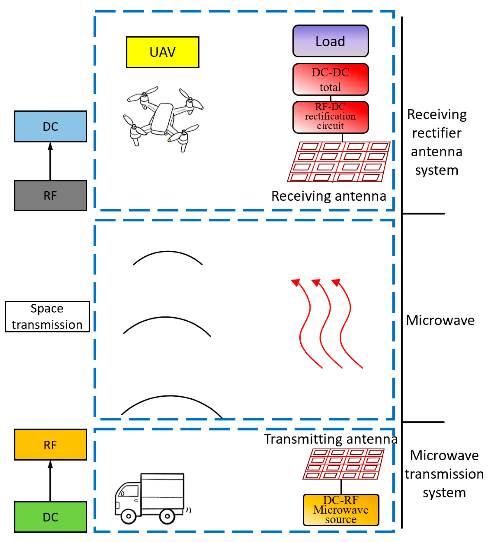
A typical ground-to-air MWPT system, as shown in Figure 1, transmits microwave energy from the ground to near-surface aircraft such as unmanned aerial vehicles (UAVs). The ground serves as the microwave wireless energy transmission device, while the underside of the UAV is equipped with a microwave-receiving rectifier device. Long-endurance UAVs can hover within a designated area. A guidance device continuously acquires the UAV’s spatial coordinates in real time and transmits them to the ground transmitter. Through beam steering control, the system adjusts the microwave transmission direction to ensure that microwave energy is always directed toward the UAV. With continuous ground-based energy supply, the UAV requires only minimal backup batteries, significantly increasing its payload capacity compared to solar-powered drones. Additionally, it eliminates the need for large-aspect-ratio wings to accommodate solar panels, offering greater aerodynamic design flexibility and simpler control strategies. Thus, MWPT technology enables truly uninterrupted mission flights for UAVs.
The efficiency of a rectifying antenna depends on two components: receiving antenna efficiency and rectifier circuit efficiency. Since antenna reception efficiency is determined by antenna performance, a well-matched antenna’s efficiency is primarily affected by dielectric loss and metal conductivity, not by the received power level. During power fluctuations, the rectifier circuit becomes the primary factor influencing efficiency.
An MWPT system is a system that allows a transmitter to provide power wirelessly to multiple nodes within a specific distance, and there are large differences in the power received by the rectifying antenna and the electromagnetic wave in MWPT systems due to the different distances, path losses, and multipath reflections between the transmitter and receiver. An antenna’s efficiency does not change for any received power. But the rectifier circuit has a diode in it, which makes it nonlinear, and so it will vary with input power. Regular rectifying circuits are only suitable for an impedance at one power point. When a change in power changes the impedance, it is called impedance mismatching, and it does not permit efficient rectification. Likewise, when we make changes in the operating frequency and load output, we see some nonlinearity changes, causing an impedance mismatch in the rectifier. This reduces efficiency. Therefore, increasing the input power, frequency and output load of a rectifier circuit will increase the efficiency of the whole wireless power transfer system.

2.2. Research Status at Home and Abroad

In recent years, domestic and foreign countries have conducted a lot of research on the receiver technology of MWPT, and a lot of work has been carried out in this field. There are many research teams and organizations that constantly study and research all aspects of this field. In doing so, they are always pushing the boundaries of tech.
Professor Mingyu Lu’s group of West Virginia University significantly influenced research worldwide. They conducted near-field wireless power delivery with phased array tech, proposed a comprehensive application framework and, after a lot of hard work, provided exact, closed-form expressions for electromagnetic radiation and the efficiency of powers [13]. This is a big deal. In terms of theory and practice, their study can provide a good basis for obtaining a deep understanding of the physical process during a near-field wireless power transmission and increase our awareness of the natural relationship between the aperture of the antenna and the borderline of the near-field region. It can be seen from their study that at 2.45 GHz, when they used phased array antennas, with a focus on 30 °FOV, they increased the power transfer by more than 25% compared to conventional single antennas. This means that at an equal transmission power, the receiver obtains more energy, thus greatly improving the performance of MWPT systems. For instance, industrial application scenarios require that the robot, machine, etc., have high energy transferring efficiency, and it is better to use phased array antenna techniques to let wireless powered robots and automated robots run forever and steadily. This reduces downtime caused by a lack of energy and enhances the production rate.
Domestically speaking, JFSLAB Hubei has dedicated a great amount of effort to the research of MWPT receiver technology and achieved considerable results. The lab used a GaN Schottky diode that they made themselves to build a 20 m long dynamic microwave power transfer system. GaN is a wide-bandgap semiconductor material that has high electron mobility, a very high breakdown electric field and excellent thermal conductivity. It is suitable for high-frequency and high-power applications. Utilizing these strengths, JFS LAB showed that wide-bandgap semiconductor devices performed better in terms of high-frequency rectification, so JFSLAB decided to charge drones at ±30-degree deflection, providing a whole new kind of wireless power to the drones. You can even use them as power banks, and they can fly and be charged, which means you can spend more time enjoying them. For example, logistic delivery drones can recharge in the air by using this kind of dynamic microwave power transfer, meaning that there is no need for frequent landings to change the batteries. This improves the speed of delivery and the operation cost is reduced. And it is also impressive that JFSLAB made a 16-unit microstrip array receiving antenna that shows good performance, capable of receiving −20 dBm in the ISM band. It can receive weak microwave signals and can also deliver power to more than one device at the same time. And this sort of function offers expansive utility to the recipient because it could be used to energize an IoT terminal, gather energy from multiple sensors and smart gadgets to enable the use of lots of devices together, and develop IoT technology.
Although MWPT receiver technology has achieved some improvements, there are still quite a lot of fundamental technical obstacles for MWPT’s practical application. This restricts the use and promotion of MWPT on a large scale.
Energy capture efficiency is an important problem. Traditional silicon-based rectifier diodes exhibit a conversion efficiency below 70% for low-input power < 10 dBm. That is to say, quite a lot of microwave energy is lost due to the poor conversion rate of power. The most fundamental issues are caused by material and structure problems of silicon materials and the diodes themselves. Moreover, the accuracy of correctly matching the receiving antenna’s impedance value has a significant effect on harvesting efficiency. When an antenna’s impedance does not match the transmission line’s impedance, this increases the reflection factor. So, some of the microwaves bounce back instead of being picked up by the antenna, which means we do not receive as much energy. For example, in a long-range wireless power transfer, there is very little microwave power at the receiver because of the range. When this happens, the silicon-type diode’s poor conversion efficiency and the impedance-matching problem render it difficult to collect energy, which is very bad for the whole system.
Additionally, inadequate adaptability to a complicated environment is a current concern. MWPT receivers are susceptible to interference in practical application environments. The most frequent form of interference is multipath fading, along with obstruction caused by objects. When microwave signals reflect, refract, scatter, etc., on obstacles before being sent, this is called multipath fading. These signals arrive at the receiver via lots of different routes. Once they get there, they begin to interfere with each other. This ends up creating a sort of irregular pattern, which has a big impact on how much power is received. Through research and testing in the field, we know that multipath fading and obstacles cause a change in the receiving power of more than 30%. It is not easy for devices that require constant energy. Let us use cities with lots of skyscrapers as an example, where microwaves encounter many reflections and blocks. This makes it difficult for the signal at the receiver to have a steady strength and phase, so it is tough to keep a steady flow of power. And on the industrial side, electromagnetic interference from sources like motors and welding machines can create, like static on your radio, electromagnetic noise that disrupts the microwave signals, meaning that the receiver does not work correctly. This means we must improve the receiving end’s dynamic response and ability to resist interference in complicated situations if we wish to use MWPT technology and make it dependable.
System integration complexity is one of the other main obstacles for existing receiver technology. Due to the development of the miniaturization and portability of electronic equipment, the demand for small MWPT receivers has become more urgent. But the major contradiction is between the need for miniaturization and the large size of high-gain antennas. In general, high-gain antennas have to be quite big to ensure they work well and point accurately at something, but there is just no room for such big antennas in little devices. For a UAV that is a very tiny size, the receiver has to capture maximum power within minimum space, and the antennas need to meet those demands, which is why we are putting so much stress on the design and installation of them. Furthermore, system integration requires parts like antennas, rectifier circuits, etc., to be connected together within a small area. With the need to ensure that they communicate well and work well together, putting these parts in place is still a huge problem. The opposite is true. The tighter its integration, the more careful we have to be about temperature. If the temperature is too hot, electronic parts will not work well and will not work as long, so we need to ensure they give off heat to keep everything working properly.

3. Key Technologies for the Receiving End

3.1. Key Technologies for Efficient Rectifier Circuits

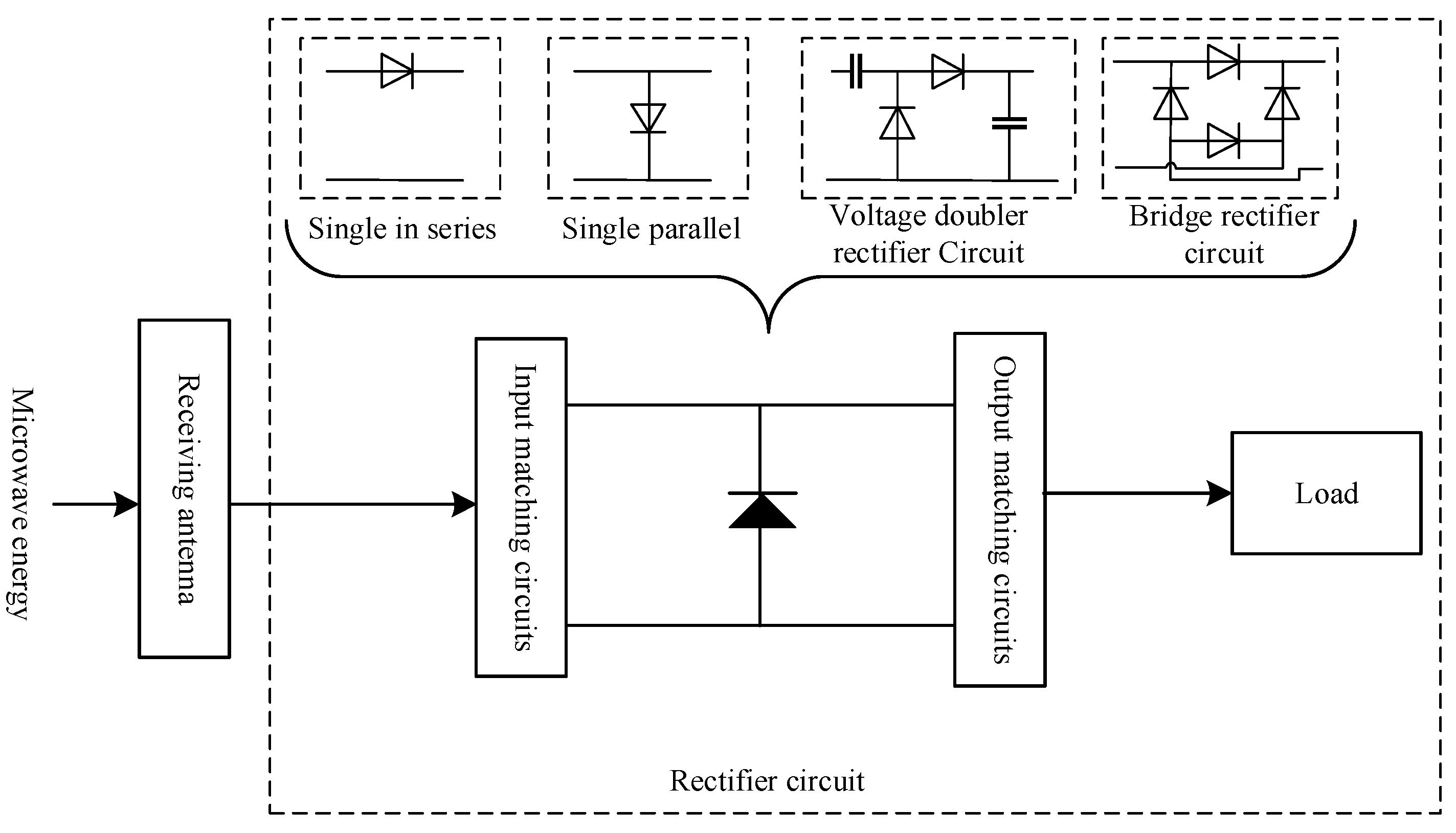
Rectifiers are circuits that take input RF energy and change it to DC energy. It is an important component of the MWPT receiver and is closely related to the efficiency of energy conversion [14]. The configuration of a rectifier circuit is shown in Figure 2, mainly including the input matching circuit, rectifying circuit, and output circuit [15].
The input matching circuit performs impedance transformation between the receiving antenna and the rectifier circuit to maximize RF power transfer to the rectifier. Simultaneously, it functions as a low-pass/band-pass filter to suppress higher-order (n ≥ 2) harmonic components generated by the rectifier, preventing these harmonic signals from being radiated by the antenna and degrading rectification efficiency. Furthermore, DC-blocking capacitors in the input matching circuit effectively transmit fundamental signals while preventing DC energy loss.
The output filter matching network typically consists of parallel capacitors or harmonic suppression networks (open-circuit or short-circuit branches). This configuration filters out fundamental and higher-order (n ≥ 2) harmonics while efficiently transferring DC energy to the load.
Table 1 compares different rectifier circuit topologies, and in practical applications, corresponding topologies can be selected according to requirements [16,17,18,19].

3.1.1. Rectifier Diodes

Rectifier diodes are a critical component of rectifier circuits, significantly determining rectification efficiency. Input power also significantly impacts rectification efficiency [20]. Insufficient input power prevents diode conduction, while excessive input power causes reverse breakdown. Therefore, rectifier diodes are typically desired to feature low forward voltage and high reverse breakdown voltage. Diodes possessing these characteristics offer a wide input power range, enabling operation at low voltages without easy breakdown under high voltages [21].
Currently, commonly used rectifier diodes employ Si and GaAs materials, belonging to first- and second-generation semiconductor materials. Due to their narrow bandgap properties, the breakdown voltage and saturation current of these devices are limited. The rectification power of a single diode is only in the range of 10–100 mW. To meet rectification needs, multiple rectifying devices are needed and they need to be arranged in parallel within a composite circuit, so the circuit has to be very large and is costly. And power combining is inevitable, resulting in the loss of some power. We need diode devices with low turn-on voltage, low junction capacitance, high current density and high breakdown voltage to overcome the problems of the high-power, high-efficiency microwave rectification of SSPSs and other high-power microwave devices. Wide-bandgap semiconductor GaN is expected to be used in the production line of microwave diodes, which may instigate a breakthrough in this field [22,23].
The GaN Schottky diode has a very small turn-on voltage of 0.3 V, so it can more easily conduct at a lower input power, and thus conduction loss is reduced. At the same time, it has a very small junction capacitance of only 0.87 pF, which means the circuit can be made as small as possible, even at a high frequency. The capacitive loss of the circuit means it can work at the highest frequency and convert energy with the highest efficiency. Taking advantage of its large band gap and high breakdown field, GaN facilitates high-power rectifier Schottky diodes. For the same power requirements, it reduces the amount of modules needed compared to GaAs and Si-based processes. It decreases cost by quite a bit [24].
Table 2 shows GaN’s energy band gap, which is over 3.1 and higher than that of Si. The electron saturation velocity of GaN is approximately 2.5 and greater than that of Si. These results enable its use in RF and power conversion [22]. GaN SBDs are regarded as the best material for improving microwave rectifier performance as they show lower losses and higher power [23].
Table 3 lists the technical specifications of rectifier diodes that have been used for wireless power transmission over the past five years. The data in Table 3 are experimentally measured results from corresponding references. It can be seen that Si SBD has lower power and a narrower bandwidth, while GaN SBD has higher power and an improved bandwidth. At the same time, it can also be seen that the rectification circuit is indeed a key factor restricting the performance of microwave wireless transmission and reception terminals, and improving its efficiency and high-efficiency power range is crucial.
However, from a cost perspective, GaN SBDs are far more expensive than Si SBDs. The cost of a single Si SBD typically ranges from a few cents to several US dollars, whereas the cost of a single GaN SBD can be as high as several hundred to several thousand US dollars. This is mainly because Si SBDs benefit from mature technologies and manufacturing processes, with large-scale mass production already achieved. In contrast, GaN SBDs face two key cost drivers: on the one hand, the substrate itself is costly, and on the other hand, production processes such as packaging are highly complex, and large-scale mass production has not yet been realized, which further increases costs. The substrate types commonly used for GaN SBDs in the RF field include GaN on SiC, GaN on Si, and GaN on GaN, with their costs roughly ranked as GaN on Si < GaN on SiC < GaN on GaN. Therefore, GaN SBDs are primarily applied in scenarios that are insensitive to cost but demand high performance, such as high-power microwave rectennas.

3.1.2. Matching Circuit

Impedance mismatch leads to energy loss. The primary reason is that when the input impedance of the rectenna is inconsistent with the load impedance, microwave signals cannot be fully transmitted to the load; instead, part of the signals are reflected back to the antenna, resulting in reflection loss. Impedance matching at the receiving end of MWPT is mainly achieved through an RF matching network, which enables conjugate matching between the input impedance of the rectenna and the load impedance, ensuring that RF energy is converted into DC energy in the rectifier circuit as much as possible. DC-DC conversion is a DC regulation stage after rectification, which can indirectly adjust the equivalent DC load impedance at the rectification end.
According to the characteristics of matching networks, they can be divided into three categories: passive fixed matching, active tunable matching, and intelligent adaptive matching. Passive fixed matching is suitable for scenarios with fixed loads and stable transmission environments; it achieves one-time matching by designing a fixed impedance transformation network with passive components. Common techniques include lumped-parameter matching network technology, distributed-parameter matching technology, and antenna structure optimization. Among these, the lumped-parameter matching network is one of the most commonly used matching methods in RF circuits. It is mainly composed of lumped components such as inductors (L) and capacitors (C), and matching for different impedances can be achieved through a reasonable selection and combination of these components. It has advantages such as a simple structure, low cost, and ease of design and debugging. In lumped-parameter matching networks, L-type, π-type, and T-type networks are the most basic topological structures [35,36].
As the operating frequency increases, the parasitic effects of lumped-parameter components become increasingly significant, greatly affecting their performance. Distributed-parameter matching technology mainly utilizes the characteristic impedance and length of transmission lines to achieve impedance transformation, which can effectively avoid the parasitic effects of lumped components and improve the performance of the matching network. Common techniques include quarter-wavelength transformers and single-stub and multi-stub matching technologies.
Optimizing the antenna structure can also make the input impedance of the antenna match the characteristic impedance of the system, reducing the loss of additional matching networks. This can be carried out, for example, by optimizing antenna dimensions and implementing feeding methods [37].
When the load changes dynamically or the transmission environment fluctuates, active tunable impedance matching must be adopted. Its principle is to adjust the network matching parameters through active components to maintain impedance matching, such as using variable reactance devices and active impedance transformation circuits.
Intelligent adaptive impedance matching technology is a future development trend. It combines sensors, algorithms, and tunable matching networks to achieve fully automatic and high-precision impedance matching, which can be realized through algorithm-based adaptive matching, conjugate matching tracking technology, distributed matching technology, etc.
A comparison of different impedance matching methods is shown in Table 4.
While impedance matching can significantly reduce reflection loss caused by impedance mismatch, it inevitably introduces new losses. The losses of passive fixed matching mainly stem from the inherent losses of components, and such losses are typically small. Active tunable matching networks rely on variable reactance devices and active control circuits to achieve dynamic adjustment, resulting in losses that are significantly greater than those of passive fixed matching. Their losses originate partly from the components themselves and partly from the additional electrical energy consumed by the active control circuits.
The losses of intelligent adaptive matching fall between the two aforementioned types. These losses primarily arise from three aspects: first, the insertion loss of the underlying tunable matching network; second, the operating loss of the impedance detection module; and third, the energy consumption of algorithm operations and the controller. Overall, the losses are relatively small, and particularly with the development of low-power chip technology, energy consumption has been further reduced.
A comparison of the losses of the three matching types is presented in Table 5. It should be pointed out that the energy loss is only a relative comparison of the three matching types.
In summary, compared with the benefits brought by impedance matching, the losses introduced by impedance matching technology can be ignored.

3.2. Key Technologies for Power Synthesis

To enhance power levels in MWPT, single rectifying antenna units are insufficient, and arraying is necessary. For instance, in 2021, researchers at Kyoto University developed lightweight rectifying antenna arrays for aerial vehicles like UAVs and HAPSs (High Altitude Platform Stations). Operating at 5.8 GHz, this rectifying antenna array achieved a conversion efficiency of 34.5% in its rectifying circuit. During a 1.08 m power transmission experiment, it supplied 1.48 W of DC power to a drone battery.
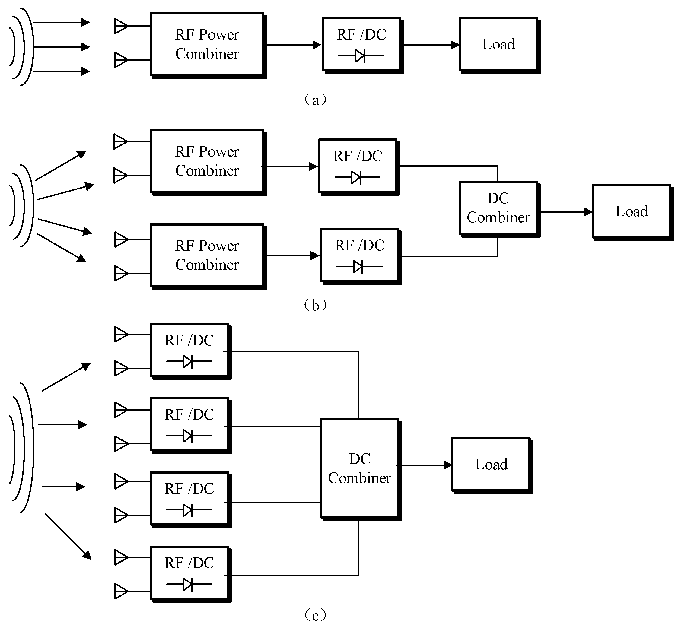
The primary array configurations encompass individual rectifier combinations, subarray combinations, and rectenna arrays, as illustrated in Figure 3. For the individual rectifier combinations, since rectifier diodes typically exhibit higher rectification efficiency at higher input powers, this scheme can harvest more energy near the main beam. For the rectenna arrays, as each rectifier circuit is in one-to-one correspondence with an antenna element, it is less sensitive to the incident wave angle. However, the individual rectifier combinations exhibit significant losses, while the rectenna arrays require a greater number of RF-DC conversion components, which increases the overall cost. Therefore, sub-array combining schemes that balance the advantages and disadvantages of the two aforementioned power combining approaches have been proposed, further optimizing the performance of the rectenna array.
RF synthesis technology first combines microwave signals received by all antenna elements via RF synthesis before unified rectification [38], as shown in Figure 3a. The advantages of this layout include fewer rectifier circuits, lower engineering complexity, and the ability to more easily match rectifier circuit power to the load. However, this layout is only suitable for low-power, small-scale receiving rectifying antenna systems. For large antenna arrays, the power divider network used for RF combining is massive, and its power loss significantly reduces the receiving efficiency of the antenna array.
The DC-combined approach involves rectifying the microwaves received by each antenna unit individually, followed by combining the DC power, as shown in Figure 3c. This method offers the advantages of eliminating power-splitting loss concerns and featuring smaller received power per antenna unit, which facilitates rectifier circuit design. However, this approach also has drawbacks. The semiconductor device that we use in microwave rectification shows quite a bit of nonlinearity, and this can be seen when the load of microwave power applied to the semiconductors changes, and the impedance also changes accordingly. This nonlinearity mostly affects the relationship between rectification efficiency and the variation in power and load, which are considered in rectifier circuit design [39]. A working rectifier circuit is most efficient at a particular power and load value. But in terms of power, the irradiation density at different parts of the receiving antenna power is not the same; generally speaking, it is stronger at the center and weaker at the edge. It is unlikely that the same amount of power will be received by every antenna at different locations if the same kind of rectifier circuit is used. Some rectifier circuits will have to function non-optimally, meaning that the receiving rectification system will have low efficiency. Using different types of rectifier circuits involves a greater variety of circuit types, increasing system complexity and design difficulty.
The antenna array is divided into several zones based on varying irradiance power densities. Within each zone, antenna elements undergo small-scale RF power combining to form subarrays of differing scales. The received power from all subarrays is then rectified individually to obtain DC power, which is finally combined, as shown in Figure 3b. By deploying smaller subarrays in high-power-density zones and larger subarrays in low-density zones, the received power across subarrays becomes balanced. This stabilizes the rectifier circuit’s input power. Combined with efficient rectifier circuit design, this approach achieves high overall efficiency for the rectifying antenna.
The array layout and subarray partitioning techniques of rectifying antennas critically influence receiver performance. Through subarray partitioning, issues such as uneven power distribution in the array and power mismatch with the rectifier circuit can be resolved, thereby improving overall rectification efficiency. In recent years, the layout technology of receiving array antennas has evolved from uniform array deployment to non-uniform array deployment and even reconfigurable intelligent surfaces (RISs). Traditional uniform subarray partitioning mostly adopts geometrically symmetric equal division methods, such as the rectangular grid equal division method, annular/circular array equal division method, etc. [40]. Non-uniform subarray partitioning is transformed into a mathematical problem of seeking the optimal solution: first, a subarray partitioning model is constructed; then, the objective function and constraint conditions are established; and finally, the optimal partitioning scheme is solved step by step through clustering and iteration. Common clustering methods include K-means clustering, Particle Swarm Optimization (PSO), and weighted clustering algorithms [41,42,43,44]. RISs regulate electromagnetic waves through low-cost controllable units, replacing traditional active arrays.
Subarray partitioning technology optimizes subarray layout and element excitation grouping to achieve equivalent radiation performance while reducing feed network complexity and antenna deployment costs. This cost-effective approach has become an effective tool for addressing phased array deployment challenges. Collective intelligence methods like matrix beamforming algorithms, genetic algorithms, and differential evolution algorithms are widely applied for element positioning and excitation optimization.
In summary, to enhance the power and efficiency of the receiving rectifier end in MWPT systems while maintaining high performance and stability, the following three approaches can be adopted.
  • Implementing load impedance matching design for rectifier circuits resolves the issue of fluctuating conversion efficiency due to load impedance variations.
  • Implementing MPPT design for the rectifier circuit can resolve the issue of conversion efficiency being affected by input power.
  • Implementing electrical isolation design for rectifying antenna arrays can address the issue of limited series-parallel configurations.

4. Research and Development Trend

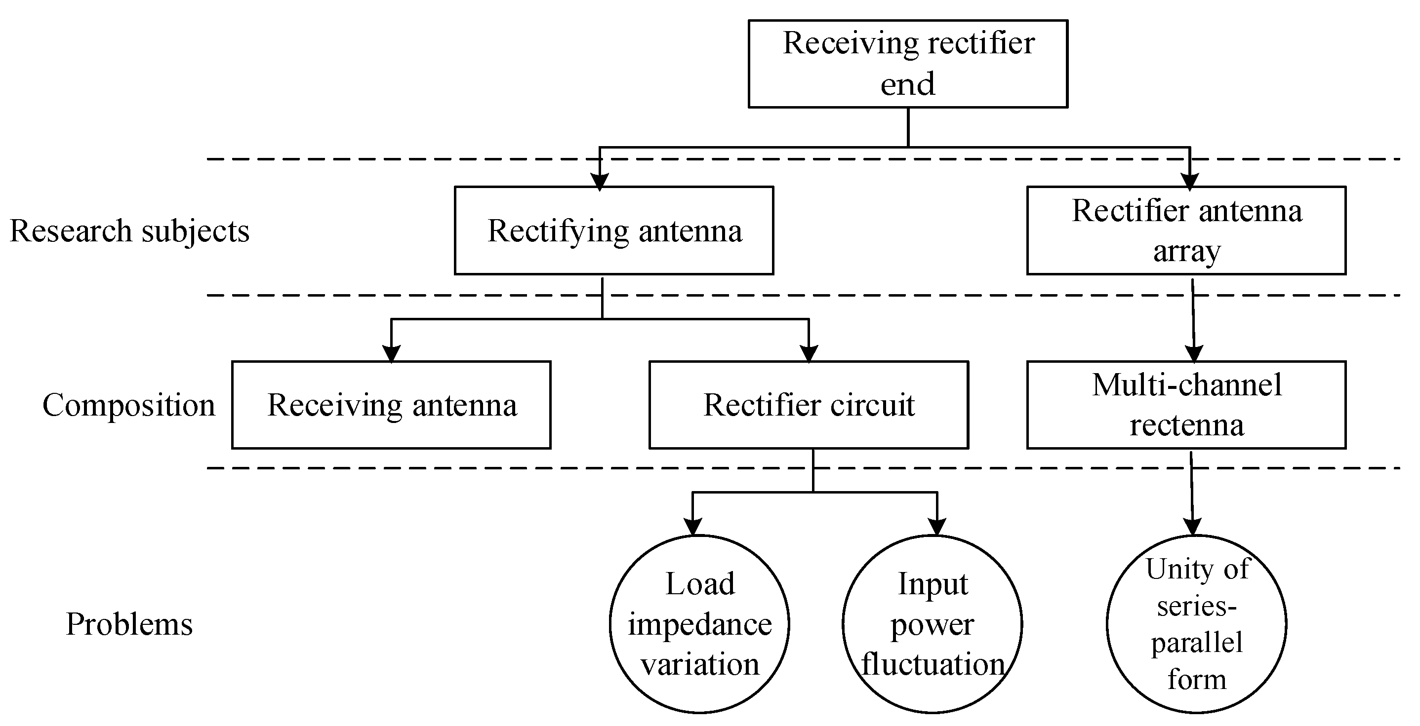
This paper primarily analyzes the structural composition, principles, current status, and key technologies of the receiving end in MWPT systems. As shown in Figure 4, research subjects for the receiving end are rectifying antennas and rectifying antenna arrays. A rectifying antenna mainly consists of a receiving antenna and a rectifying circuit, while a rectifying antenna array comprises multiple rectifying antennas. After our discussion, we can see that rectifier circuits are important for the receiver side. Currently the problem that causes difficulty in rectifier circuits lies in changes in the current and fluctuations in the input power. Rectifier antenna arrays with a single series-parallel configuration have limitations; they cannot reach the demands of high power and high efficiency. According to the above, this paper studies the main technologies that face existing issues and considers further developments such as miniature monolithic rectifier ICs and more efficient broadband rectification, which are required based on evolving needs.
1.
Miniaturized Rectifier Monolithic Microwave Integrated Circuit (MMIC) Design
For some specialized applications, there is a requirement that all modules and systems are reduced to meet specific size requirements. Therefore, investigating rectifier MMICs is quite beneficial. MMICs are the primary technology for converting RF/microwaves energy into DC energy, aiming to design an extremely high-efficient, small-sized and low-power-consuming energy harvesting system that can be applied at a high frequency. They have wide applications in wireless power transfer and the power transfer of IoT sensors, implantable medical devices, energy in space, etc.
2.
High-Efficiency Broadband Rectification
To catch a broader range of RF energy, we shall seek to procure rectifiers that feature multichannels and are adjustable for more coverage. In future work, we will increase the operational bandwidth and try switches and tunable components that allow us to switch and use different energy sources if we want to. Researching new smart algorithms, new structures, and more advanced materials will improve rectifier circuit power and efficiency and bandwidth.

5. Conclusions

MWPT has become a solution to the world’s energy problem, and its use also applies to space solar power, remote power supply, aerospace, and biomedicine. As it predominately determines the efficiency and stability of MWPT systems, the receiver is really key to the transition of MWPT systems from lab study to real-world use. This article explores MWPT research, concentrating on rectifier efficiency constraints and power synthesis consistency, which are two key snags. In a static case, the nonlinearity of standard Si/GaAs diodes is very bad, and it becomes even worse under dynamic and non-uniform antenna irradiance. But still, progress has been made: improvements in GaN-based Schottky diodes enhance the high-frequency, high-power rectification of sun power, and there are new ways to conduct activities like subarray synthesis and impedance matching, enabling MPPT to perform more efficiently with lower losses. Other challenges include the poor capture rate of low-power rectifiers, poor adaptability to the environment and the compromise between the need for miniaturization and the large size of high-gain antennas. Future work will be conducted on making Miniaturized Rectifier MMICs for smaller devices to improve reconfigurable high-efficiency broadband rectification. These advancements will enrich MWPT’s theoretical framework, facilitate its engineering and large-scale application, and advance the efficient utilization of clean energy.

Author Contributions

Conceptualization, M.R. and X.W.; validation, W.X. and L.H.; formal analysis, J.C.; investigation, K.W.; resources, J.C.; data curation, W.X.; writing—original draft preparation, M.W.; writing—review and editing, M.R.; visualization, Y.Y.; supervision, J.C.; project administration, X.W.; funding acquisition, J.C. All authors have read and agreed to the published version of the manuscript.

Funding

This research received no external funding.

Data Availability Statement

No new data were created or analyzed in this study.

Acknowledgments

We appreciate the constructive feedback from the anonymous reviewers, which greatly improved this manuscript.

Conflicts of Interest

The authors declare no conflicts of interest.

References

  1. Kawasaki, S.; Kishikawa, R.; Furuse, Y.; Nakaoka, T.; Yoshida, S.; Nishikawa, K.; Seita, H. C-band energy harvester by Si RFICs with GaN diodes for microwave power transfer. In Proceedings of the 2017 IEEE International Symposium on Radio-Frequency Integration Technology (RFIT), Seoul, Republic of Korea, 30 August–1 September 2017; pp. 147–149. [Google Scholar] [CrossRef] [Scilit]
  2. Muhammad Jibran, K.; Nida Tabassum, K. Energy Acquisition Through Wireless Power Transfer. J. Prog. Eng. Phys. Sci. 2022, 1, 23–26. [Google Scholar] [CrossRef] [Scilit]
  3. Vincent, D.; Huynh, P.S.; Patnaik, L.; Williamson, S.S. Prospects of Capacitive Wireless Power Transfer (C-WPT) for Unmanned Aerial Vehicles. In Proceedings of the 2018 IEEE PELS Workshop on Emerging Technologies: Wireless Power Transfer (Wow), Montreal, QC, Canada, 3–7 June 2018; pp. 1–5. [Google Scholar] [CrossRef] [Scilit]
  4. Zeng, Y.; Clerckx, B.; Zhang, R. Communications and Signals Design for Wireless Power Transmission. IEEE Trans. Commun. 2017, 65, 2264–2290. [Google Scholar] [CrossRef] [Scilit]
  5. Zhang, Z.; Pang, H.; Georgiadis, A.; Cecati, C. Wireless Power Transfer—An Overview. IEEE Trans. Ind. Electron. 2019, 66, 1044–1058. [Google Scholar] [CrossRef] [Scilit]
  6. Amgothu, R. Wireless Power Transmission of Solar Energy from Space to earth using microwaves. Int. J. Innov. Res. Technol. 2017, 4, 326–330. [Google Scholar]
  7. Ayir, N.; Riihonen, T.; Heino, M. Practical Waveform-to-Energy Harvesting Model and Transmit Waveform Optimization for RF Wireless Power Transfer Systems. IEEE Trans. Microw. Theory Tech. 2023, 71, 5498–5514. [Google Scholar] [CrossRef] [Scilit]
  8. Shinohara, N. History and Innovation of Wireless Power Transfer via Microwaves. IEEE J. Microw. 2021, 1, 218–228. [Google Scholar] [CrossRef] [Scilit]
  9. Ullah, M.A.; Keshavarz, R.; Abolhasan, M.; Lipman, J.; Esselle, K.P.; Shariati, N. A Review on Antenna Technologies for Ambient RF Energy Harvesting and Wireless Power Transfer: Designs, Challenges and Applications. IEEE Access 2022, 10, 17231–17267. [Google Scholar] [CrossRef] [Scilit]
  10. Dehmas, M.; Challal, M.; Arous, A.; Haif, H. A Novel Design of a Microstrip Antenna Array for Wireless Power Transfer Applications. Wirel. Pers. Commun. 2024, 134, 581–596. [Google Scholar] [CrossRef] [Scilit]
  11. Odiamenhi, M.; Jahanbakhsh Basherlou, H.; Hwang See, C.; Ojaroudi Parchin, N.; Goh, K.; Yu, H. Advancements and Challenges in Antenna Design and Rectifying Circuits for Radio Frequency Energy Harvesting. Sensors 2024, 24, 6804. [Google Scholar] [CrossRef] [Scilit]
  12. Chen, D.; Li, R.; Xu, J.; Li, D.; Fei, C.; Yang, Y. Recent progress and development of radio frequency energy harvesting devices and circuits. Nano Energy 2023, 117, 108845. [Google Scholar] [CrossRef] [Scilit]
  13. Xiao, H.; Zhang, H.; Song, W.; Wang, J.; Chen, W.; Lu, M. A High-Input Power Rectifier Circuit for 2.45-GHz Microwave Wireless Power Transmission. IEEE Trans. Ind. Electron. 2022, 69, 2896–2903. [Google Scholar] [CrossRef] [Scilit]
  14. Halimi, M.A.; Al-Naib, I.; Attia, H. Multi-Band Microwave Rectifiers for RF Energy Harvesting: A Comprehensive Review of Design Techniques and Performance Analysis. IEEE Access 2025, 13, 140061–140078. [Google Scholar] [CrossRef] [Scilit]
  15. Zhang, Z.; Gu, C.; Cheng, Z.; Xuan, X. Design a GaN HEMT-Based Broadband High-Efficiency Rectifier Using a Wideband Phase Shift Structure. IEEE Microw. Wirel. Technol. Lett. 2023, 33, 751–754. [Google Scholar] [CrossRef] [Scilit]
  16. Hashimoto, T.; Tanzawa, T. Design Space Exploration of Antenna Impedance and On-Chip Rectifier for Microwave Wireless Power Transfer. Electronics 2022, 11, 3218. [Google Scholar] [CrossRef] [Scilit]
  17. Hashimoto, T.; Nekozuka, H.; Toeda, Y.; Otani, M.; Fukuoka, Y.; Tanzawa, T. A −31.7 dBm Sensitivity 0.011 mm2 CMOS On-Chip Rectifier for Microwave Wireless Power Transfer. Electronics 2023, 12, 1400. [Google Scholar] [CrossRef] [Scilit]
  18. Tan, F.; Liu, C. Design of a High-Conversion-Efficiency X-Band Rectifier for Microwave Wireless Power Transmission. In Proceedings of the 2018 International Conference on Microwave and Millimeter Wave Technology (ICMMT), Chengdu, China, 7–11 May 2018; pp. 1–3. [Google Scholar] [CrossRef] [Scilit]
  19. Rotenberg, S.A.; Podilchak, S.K.; Re, P.D.H.; Mateo-Segura, C.; Goussetis, G.; Lee, J. Efficient Rectifier for Wireless Power Transmission Systems. IEEE Trans. Microw. Theory Tech. 2020, 68, 1921–1932. [Google Scholar] [CrossRef] [Scilit]
  20. Pu, T.; Li, X.; Wang, X.; Bu, Y.; Zhao, W.; Chen, Z.; Ao, J.P. GaN Schottky barrier diodes for microwave power transmission. In Proceedings of the 2018 IEEE MTT-S International Wireless Symposium (IWS), Chengdu, China, 6–10 May 2018; pp. 1–4. [Google Scholar] [CrossRef] [Scilit]
  21. Li, Q.X.; Li, Y.; Liu, T.; Huang, R.P.; Zhu, X.; Liu, P.B.; Wang, X.; Chen, Z.W.; You, J.; Liu, Z.C.; et al. Design and Fabrication of Milliwatt and Microwatt Microwave Rectifiers Based on Low Turn-On GaN Schottky Barrier Diodes. IEEE Microw. Wirel. Technol. Lett. 2025, 35, 444–447. [Google Scholar] [CrossRef] [Scilit]
  22. Sun, R.; Lai, J.; Chen, W.; Zhang, B. GaN Power Integration for High Frequency and High Efficiency Power Applications: A Review. IEEE Access 2020, 8, 15529–15542. [Google Scholar] [CrossRef] [Scilit]
  23. Li, Y.; Pu, T.F.; Li, X.B.; Zhong, Y.R.; Yang, L.A.; Fujiwara, S.; Kitahata, H.; Ao, J.P. GaN Schottky Barrier Diode-Based Wideband and Medium-Power Microwave Rectifier for Wireless Power Transmission. IEEE Trans. Electron Devices 2020, 67, 4123–4129. [Google Scholar] [CrossRef] [Scilit]
  24. Yu, X.; Wang, H.; Liu, Y.; Huang, P.Y.; Yen, T.J.; Hsu, S.S.H.; He, Y.; Song, C.; Huang, Y.; Zhou, J. A Custom C Band High-Power GaN-Based Rectifier for WPT Systems. In Proceedings of the 2025 IEEE Wireless Power Technology Conference and Expo (WPTCE), Rome, Italy, 3–6 June 2025; pp. 1–4. [Google Scholar] [CrossRef] [Scilit]
  25. Dang, K.; Zhang, J.; Zhou, H.; Huang, S.; Zhang, T.; Bian, Z.; Zhang, Y.; Wang, X.; Zhao, S.; Wei, K.; et al. A 5.8-GHz High-Power and High-Efficiency Rectifier Circuit with Lateral GaN Schottky Diode for Wireless Power Transfer. IEEE Trans. Power Electron. 2020, 35, 2247–2252. [Google Scholar] [CrossRef] [Scilit]
  26. He, Z.; Lin, H.; Liu, C. A Novel Class-C Rectifier with High Efficiency for Wireless Power Transmission. IEEE Microw. Wirel. Compon. Lett. 2020, 30, 1197–1200. [Google Scholar] [CrossRef] [Scilit]
  27. Chen, J.; Guo, L.; Yang, J.; Xiao, L.; Zhang, X.; Chen, L.; Yang, M. Investigation of high power and efficiency microwave power transfer system at 5.8GHz. In Proceedings of the 2021 13th International Symposium on Antennas, Propagation and EM Theory (ISAPE), Zhuhai, China, 1–4 December 2021; pp. 1–3. [Google Scholar] [CrossRef] [Scilit]
  28. Chang, M.; Xue, H.; Wu, X.; Zhang, S.; Cheng, F.; Li, L. High Power and Wide Input Power Range Rectifying Metasurface with GaN Diode. In Proceedings of the 2021 IEEE MTT-S International Microwave Workshop Series on Advanced Materials and Processes for RF and THz Applications (IMWS-AMP), Chongqing, China, 15–17 November 2021; pp. 179–181. [Google Scholar] [CrossRef] [Scilit]
  29. Yi, X.; Chen, Q.; Hao, S.; Chen, X. An efficient 5.8 GHz microwave wireless power transmission system. Int. J. RF Microw. Comput.-Aided Eng. 2022, 32, e23094. [Google Scholar] [CrossRef] [Scilit]
  30. Xu, R.; Liu, T.; Li, Y.; Huang, R.P.; Li, Q.X.; Shao, B.; Fan, X.M.; Yang, L.A. A 5.8-GHz GaN-Based Rectifier with High Power and High Efficiency. In Proceedings of the 2023 IEEE MTT-S International Wireless Symposium (IWS), Qingdao, China, 14–17 May 2023; pp. 1–3. [Google Scholar] [CrossRef] [Scilit]
  31. Nguyen, D.A.; Nam, H.; Seo, C. Design of Compact Class-F High-Efficiency Shunt-Diode Rectifier with Extended Harmonic Termination for Wireless Power Transfer. IEEE Microw. Wirel. Technol. Lett. 2023, 33, 78–81. [Google Scholar] [CrossRef] [Scilit]
  32. Li, S.; Xu, X.; Kang, X.; Lan, J.; Yue, Z.; Zhao, R.; Wu, H.; Liu, X.; Lin, X. High-Efficiency and High-Power Rectifiers Using Cost-Effective AlGaN/GaN Schottky Diode with Accurate Large-Signal Parameter Extraction. IEEE Microw. Wirel. Technol. Lett. 2024, 34, 560–563. [Google Scholar] [CrossRef] [Scilit]
  33. Cui, Y.; Dang, K.; Zhang, J.; Huo, S.; Weng, J.; Wang, Z.; Hao, Y. A 5.8-GHz High-Efficiency Inverse Class-F Rectifier Circuit with GaN Schottky Diode. In Proceedings of the 2024 9th International Conference on Integrated Circuits and Microsystems (ICICM), Wuhan, China, 25–27 October 2024; pp. 292–296. [Google Scholar] [CrossRef] [Scilit]
  34. Huang, L.; Lu, Y.L.; Li, H.L.; Wang, C.; Wei, Y.; Huang, K.M.; Qian, S.H.; Wang, C. Development of AlGaN/GaN Schottky Diodes and Rectifiers Based on Innovative Loss Model for Wireless Power Transfer. IEEE Trans. Microw. Theory Tech. 2025, 73, 6129–6138. [Google Scholar] [CrossRef] [Scilit]
  35. Wei, M.D.; Fan, C.Y.; Dietrich, F.; Negra, R. General Solution of a Rectifier Using an Inductive Matching Network. IEEE Microw. Wirel. Compon. Lett. 2020, 30, 1173–1176. [Google Scholar] [CrossRef] [Scilit]
  36. Scheder, A.; Zocher, N.; Vossiek, M. It’s a Match. IEEE Microw. Mag. 2025, 26, 119–126. [Google Scholar] [CrossRef] [Scilit]
  37. Ribeiro, H.; Matos, D.; Carvalho, N.B.; Georgiadis, A. Enhancement of RF-DC Converters Efficiency by Input Impedance Optimization. IEEE Access 2024, 12, 182708–182716. [Google Scholar] [CrossRef] [Scilit]
  38. Liu, Z.; Li, T.; Li, S.; Mi, C.C. Advancements and challenges in wireless power transfer: A comprehensive review. Nexus 2024, 1, 100014. [Google Scholar] [CrossRef] [Scilit]
  39. Woo, J.M.; Lim, W.; Bae, J.; Song, C.M.; Lee, K.J.; Yi, S.H.; Yang, Y. Extendable Array Rectenna for a Microwave Wireless Power Transfer System. IEEE Access 2021, 9, 98348–98360. [Google Scholar] [CrossRef] [Scilit]
  40. Zeng, H.; Xu, Z.; Dong, W.; Xiao, S. Phase-Only Shaped Beam Synthesis for Large-Scale Array with the Guidance of Beam Shape. IEEE Trans. Antennas Propag. 2025. [Google Scholar] [CrossRef] [Scilit]
  41. Miao, K.; Zhang, Y.; Yao, C.; Sun, H. Improved Algorithm X for Subarray Partition with Acceleration and Sidelobe Suppression. IEEE Antennas Wirel. Propag. Lett. 2022, 21, 1403–1407. [Google Scholar] [CrossRef] [Scilit]
  42. Dai, H.; Shen, W.; Ding, L.; Gong, S.; An, J. Subarray Partition Algorithms for RIS-Aided MIMO Communications. IEEE Internet Things J. 2022, 9, 16196–16208. [Google Scholar] [CrossRef] [Scilit]
  43. Chen, J.Y.; Xu, Z.H.; Xiao, S.P. Optimal Subarray Design Method for Sidelobe Cancellation of Wideband Irregular Subarrayed Array. IEEE Antennas Wirel. Propag. Lett. 2023, 22, 2793–2797. [Google Scholar] [CrossRef] [Scilit]
  44. Jiyuan, C.; Xu, Z.H.; Shunping, X. Irregular Subarray Design Strategy Based on Weighted L1 Norm Iterative Convex Optimization. IEEE Antennas Wirel. Propag. Lett. 2022, 21, 376–380. [Google Scholar] [CrossRef] [Scilit]
Figure 1. A typical ground-to-air MWPT system.
Energies 19 00438 g001
Figure 2. Rectifier circuit and its components.
Energies 19 00438 g002
Figure 3. Architectures of MWPT receiver. (a) Individual rectifier combinations; (b) subarray combinations; (c) rectenna arrays.
Energies 19 00438 g003
Figure 4. Future trends (receiving end).
Energies 19 00438 g004
Table 1. Comparison of rectifier topology structures.
Rectifier
Topologies
Number of DiodesRectification MethodOutput Voltage
Characteristics
EfficiencyPower
Capacity
Application
Single in series1half-waveLow, big fluctuationLowSmallMicro low-power devices
Single parallel1half-waveLow, big fluctuationExtremely lowSmallLoad requiring reverse voltage protection
Voltage doubler rectifier circuit2Full wave
(voltage-doubling)
High, significant fluctuationmediummediumHigh-voltage and low-current equipment
Bridge rectifier circuit4Full waveMedium to high, small fluctuationHighBigMedium to high power, stable power supply scenario
Table 2. Comparison of performance parameters for common semiconductor materials.
ParametersSiGaAs4H-SiCGaN
Band gap (eV)1.11.423.263.39
Intrinsic carrier concentration (cm−3)1.15 × 10101.5 × 1068 × 10−91.9 × 10⁻¹⁰
Relative permittivity11.813.1109
Electron mobility (cm2/(V·s))135085007002000
Electron saturation velocity (107 cm/s)1.01.02.02.5
Breakdown field Strength (MV/cm)0.30.43.03.3
Coefficient of thermal conductivity (W/(cm·K))1.50.433.3–4.51.3
Table 3. GaN SBD specifications.
Refs.Freq
(GHz)
DiodePeak EfficiencyPin
(dBm)
High-Efficiency Power RangeYear
[24]5.8GaN SBD77.4%3970% (31–40 dBm)2025
[25]5.8GaN SBD75.5%3460% (26–37 dBm)2020
[26]2.45Si SBD82.7%2570% (16–26 dBm)2020
[27]5.8GaN SBD70%3360% (27–33 dBm)2021
[28]5.8GaN SBD74%3360% (28.8–36 dBm)2021
[29]5.8Si SBD77%22.3Not Available2022
[30]5.8GaN SBD72.4%33.460% (25–35 dBm)2023
[31]2.4Si SBD82.8%1570% (4–13 dBm)2023
[32]5.8GaN SBD78.9%3170% (25–35 dBm)2024
[33]5.8GaN SBD81.9%2970% (19–33 dBm)2024
[34]5.8GaN SBD
(10 nm)
80.225.460% (17–28.5 dBm)2025
5.8GaN SBD
(20 nm)
74.42360% (17–28.5 dBm)2025
Table 4. Comparison of impedance matching methods.
Matching TypeFeatureApplicationAdvantageDisadvantage
Passive fixedSimple structure, low cost, staticFixed load, short distance, static MWPT systemLow loss and high reliabilityUnable to adapt to changes in load/environment
Active tunableDynamic adjustment, fast responseDynamic load, medium distance MWPT systemStrong adaptability and good real-time performanceHigh insertion loss and limited power capacity
Intelligent adaptiveAutomatic, high precision, closed loopLong distance, multi node, dynamic MWPT systemWide adaptability and stable efficiencyComplex structure, high cost, and complex algorithm
Table 5. A comparison of the losses of the three matching types.
Matching TypeEnergy LossCauses of Loss
Passive fixedLowOhmic and dielectric losses of passive components, conductor and dielectric losses of transmission lines
Active tunableLargeInsertion loss of variable reactance devices and additional energy consumption of active control circuits
Intelligent adaptiveMediumAdjustable network insertion loss, detection module energy consumption, controller and algorithm computation energy consumption
Disclaimer/Publisher’s Note: The statements, opinions and data contained in all publications are solely those of the individual author(s) and contributor(s) and not of MDPI and/or the editor(s). MDPI and/or the editor(s) disclaim responsibility for any injury to people or property resulting from any ideas, methods, instructions or products referred to in the content.