Article

Multibeam Hybrid Beamforming System with Reduced RF Chains for Microwave Power Transfer
Department of Electronics, Information and Communication Engineering, Konkuk University, Seoul 05029, Republic of Korea
*
Author to whom correspondence should be addressed.
Energies 2026, 19(12), 2828; https://doi.org/10.3390/en19122828
Submission received: 14 May 2026 / Revised: 8 June 2026 / Accepted: 11 June 2026 / Published: 13 June 2026
(This article belongs to the Special Issue Design, Modelling and Analysis for Wireless Power Transfer Systems)

Abstract

This paper presents a multibeam hybrid beamforming (MHBF) architecture for microwave power transfer (MPT), enabling wireless power delivery to multiple receivers with a reduced number of RF chains. The proposed architecture decouples beam control into the horizontal and vertical dimensions, where horizontal multibeams are generated in the baseband through digital precoding, while the vertical beam direction is controlled by a Butler-matrix-based analog beamformer. In particular, multibeam transmission is achieved using multi-tone signals with distinct phase weights assigned to each tone, enabling beams to be steered toward different directions, while the Butler-matrix-based analog beamformer provides vertical beam-steering capability. Compared with fully digital beamforming (DBF), MHBF enables simultaneous multibeam formation in the horizontal domain with fewer RF chains, thereby reducing hardware overhead and system complexity. To validate the proposed architecture, a 5.8 GHz prototype was designed and fabricated. The experimental results demonstrate three-beam and four-beam operation under a transmit power of 30.57 dBm, while the average received RF power in the single-beam case was 12.11 dBm at a distance of 1 m. In the three-beam and four-beam cases, average received RF power levels of 7.3 dBm and 6.1 dBm per beam were achieved, respectively. RF-to-DC conversion measurements under 430 Ω and 680 Ω load conditions further showed average PCE values of up to 38.77% and 35.05% for the three-beam and four-beam cases, respectively. These results confirm the feasibility of simultaneous multibeam wireless power delivery and its potential as an effective solution for multi-receiver operation with reduced RF-chain requirements.

1. Introduction

Wireless power transfer (WPT) has been extensively studied for a wide range of applications, including biomedical implants, Internet of Things (IoT) devices, and electric vehicle (EV) charging systems [1,2,3,4]. Among various WPT techniques, microwave power transfer (MPT) has strong potential due to its capability for long-distance energy delivery and spatial power focusing enabled by beamforming [5,6]. In practical environments, multiple receivers are spatially distributed, necessitating multibeam transmission for power delivery. Accordingly, various studies have been conducted on multibeam transmission techniques [7,8,9,10,11,12,13,14]. In refs. [7,8], Butler matrix networks and antenna arrays based on substrate integrated waveguide (SIW) structures were designed. A metamaterial-based thin planar lens antenna was proposed for multibeam operation at 28 GHz [9]. Time-division-based digital beamforming (DBF) techniques have also been investigated for power delivery through sequential beam switching [10,11]. To enable simultaneous multibeam transmission, frequency-division-based techniques using multiple frequency components have been investigated [12,13]. Moreover, a direct-digital-synthesizer-based DBF architecture has been explored for simultaneous multibeam generation at Ka-band [14]. However, these DBF architectures [12,13,14] require an RF chain for each antenna element, resulting in increased system complexity and hardware overhead. To address this limitation, hybrid beamforming (HBF), which combines digital and analog beamforming, has been introduced to employ fewer RF chains than fully digital beamforming [15]. Among HBF architectures, the partially-connected structure achieves lower system complexity than the fully connected structure by simplifying the analog beamforming network [16], while also offering higher power efficiency and maintaining comparable performance [17]. This article proposes a multibeam hybrid beamforming (MHBF) architecture for multi-receiver wireless power transmission with reduced RF chain requirements. The proposed architecture decouples beam control into horizontal and vertical dimensions, allowing independent beamforming functions to be assigned to each domain. One dimension is utilized to generate multiple beams for simultaneous power delivery, while the other dimension operates with a fixed set of beam directions in the orthogonal plane. To realize this functionality, multibeams are synthesized in the baseband via digital precoding, whereas the orthogonal beam mode control is implemented using a Butler-matrix-based analog beamformer. As a result, this architecture integrates analog beamforming with digital processing to balance flexibility and system complexity, while reducing RF chain requirements by confining digital beamforming to a single dimension. To validate the proposed approach, a 5.8 GHz prototype was designed and fabricated. The experimental results demonstrate simultaneous three-beam and four-beam RF power delivery using multi-tone continuous-wave (CW) signals. Furthermore, the multibeam radiation characteristics are evaluated by measuring the relative received RF power at a distance of 1 m, and RF-to-DC conversion measurements under different load conditions were performed to verify the rectified DC power output.
The remainder of this paper is organized as follows. Section 2 describes the proposed system architecture and signal model. Section 3 presents the design, fabrication, and RF characterization of the Butler matrix used as the vertical analog beamformer. Section 4 presents the implementation of a 5.8 GHz proof-of-concept prototype and validates the proposed architecture through multibeam radiation measurements.

2. Proposed MHBF System

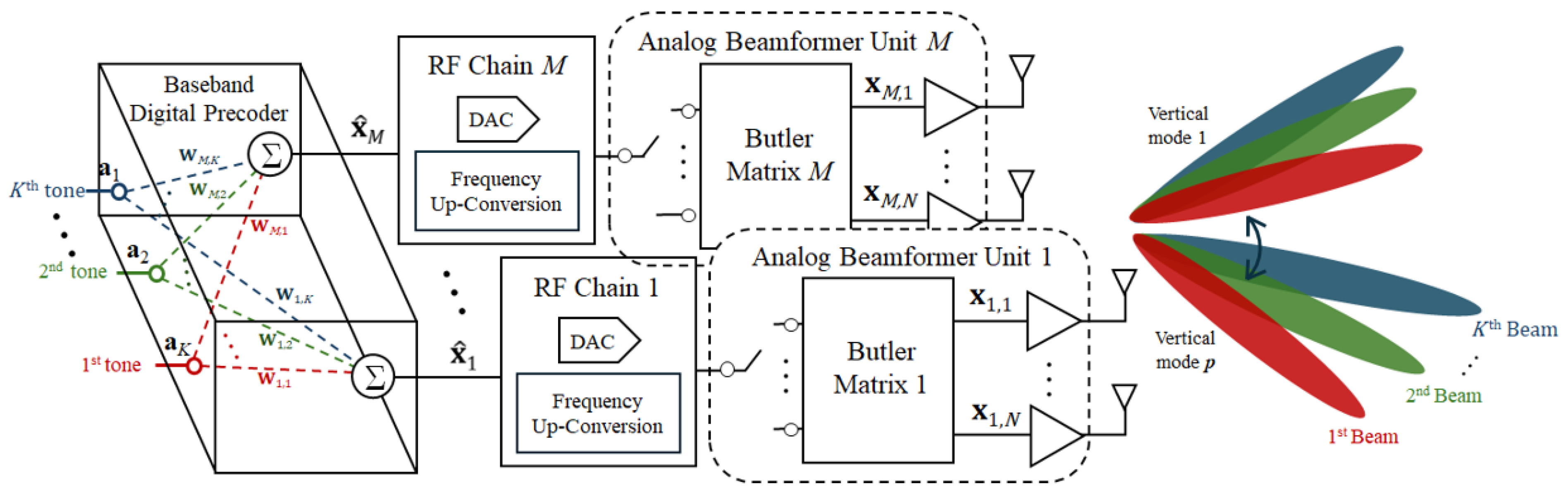
Figure 1 shows the proposed MHBF architecture, comprising a baseband digital precoder, RF chains, and Butler-matrix-based analog beamformer units, followed by power amplifiers and an antenna array. At the baseband stage, K multi-tone signals are generated, with each tone independently weighted and mapped onto the M RF chains. Distinct phase weights are assigned to the tones, allowing them to be radiated toward different horizontal directions. In the RF chains, digitally precoded baseband signals are converted from digital to analog and then upconverted to the RF band. The analog beamformer units determine the p-th vertical beam mode through the input-port selection of Butler matrices, which share a common input port. Therefore, the proposed architecture performs beam control in the horizontal and vertical directions, providing an effective architecture for two-dimensional beam control.

2.1. Signal Model and Array-Factor Decomposition

The signal model for the proposed MHBF architecture is formulated to describe the mapping onto the M × N antenna array and is presented separately for the horizontal and vertical dimensions. Using the elevation angle θ and the azimuth angle φ , the corresponding direction cosines along the horizontal and vertical dimensions are defined as
u = sin θ cos φ , v = sin θ sin φ .
Then, the array factor associated with the k-th tone and the p-th vertical beam mode can be expressed in the separable form
A F k , p ( θ , φ ) = m = 1 M e j ( m 1 ) 2 π λ d x u e j ψ m , k × n = 1 N e j ( n 1 ) 2 π λ d y v e j ψ n , p ,
where ψ m , k denotes the digital-precoding phase weight applied along the horizontal dimension for the k-th tone, and ψ n , p denotes the Butler-induced phase weight applied along the vertical dimension for the p-th Butler input-port selection. The terms associated with d x and d y represent the geometric phase progression of the M × N antenna array with inter-element spacings d x and d y , respectively. Here, λ denotes the wavelength at the carrier frequency f c under the narrowband assumption.

2.2. Horizontal Digital-Precoding Weights

To explicitly represent the multi-tone signal generation, let
a ( t ) = a 1 ( t ) a 2 ( t ) a K ( t ) T C K × 1 ,
where the k-th component denotes a tone at frequency f k , given by
a k ( t ) = e j 2 π f k t , f k = f c + k Δ f , k = 1 , , K ,
where λ c denotes the wavelength corresponding to the center frequency f c . Since the tone spacing Δ f is sufficiently small, the variation in wavelength across tones is neglected. The horizontal phase weight ψ m , k is given by
ψ m , k = 2 π λ c ( m 1 ) d x u k , m = 1 , , M ,
where u k denotes the horizontal direction cosine of the k-th tone. Based on (5), the horizontal weighting matrix W is constructed as
W = e j ψ 1 , 1 e j ψ 1 , 2 e j ψ 1 , K e j ψ 2 , 1 e j ψ 2 , 2 e j ψ 2 , K e j ψ M , 1 e j ψ M , 2 e j ψ M , K C M × K ,
where each column corresponds to the spatial weighting vector for the k-th tone, forming a beam toward the designated horizontal direction. The digitally weighted signal vector across the M RF chains is then expressed as
x ^ ( t ) = W a ( t ) C M × 1 .

2.3. Vertical Analog Beamformer Weights from Butler-Port Selection

The vertical phase weight ψ n , p is given by
ψ n , p = ( n 1 ) β p , n = 1 , , N ,
where β p denotes the per-element phase increment associated with the p-th port. For an ideal N × N Butler matrix,
β p = ( 2 p 1 ) π N , p = 1 , , N .
The corresponding vertical steering vector is given by
b ( p ) = 1 e j β p e j 2 β p e j ( N 1 ) β p T C N × 1 .

2.4. MHBF Signal Mapping

The outputs of the M RF chains are individually applied to Butler-matrix-based analog beamformer units by exciting the selected input port p while terminating the remaining unexcited ports. Applying a common port p to all analog beamformer units enforces the same vertical phase progression across all horizontal branches, which is represented by b ( p ) in (10). The resulting excitation vector for the full M N -element array is written as
x ( t ) = b ( p ) x ^ ( t ) = b ( p ) W a ( t ) C M N × 1 ,
where ⊗ denotes the Kronecker product. Equivalently, the excitation of the ( m , n ) -th antenna element is given by
x m , n ( t ) = b ( p ) n x ^ ( t ) m = e j ( n 1 ) β p k = 1 K e j ψ m , k a k ( t ) .
When K beams are transmitted simultaneously, the available power is equally divided among the beams. Since each beam is formed independently, the received power per beam is reduced by 10 log 10 ( K ) dB compared with the single-beam case.

3. Butler-Matrix Beamforming Network: Design and Measurement

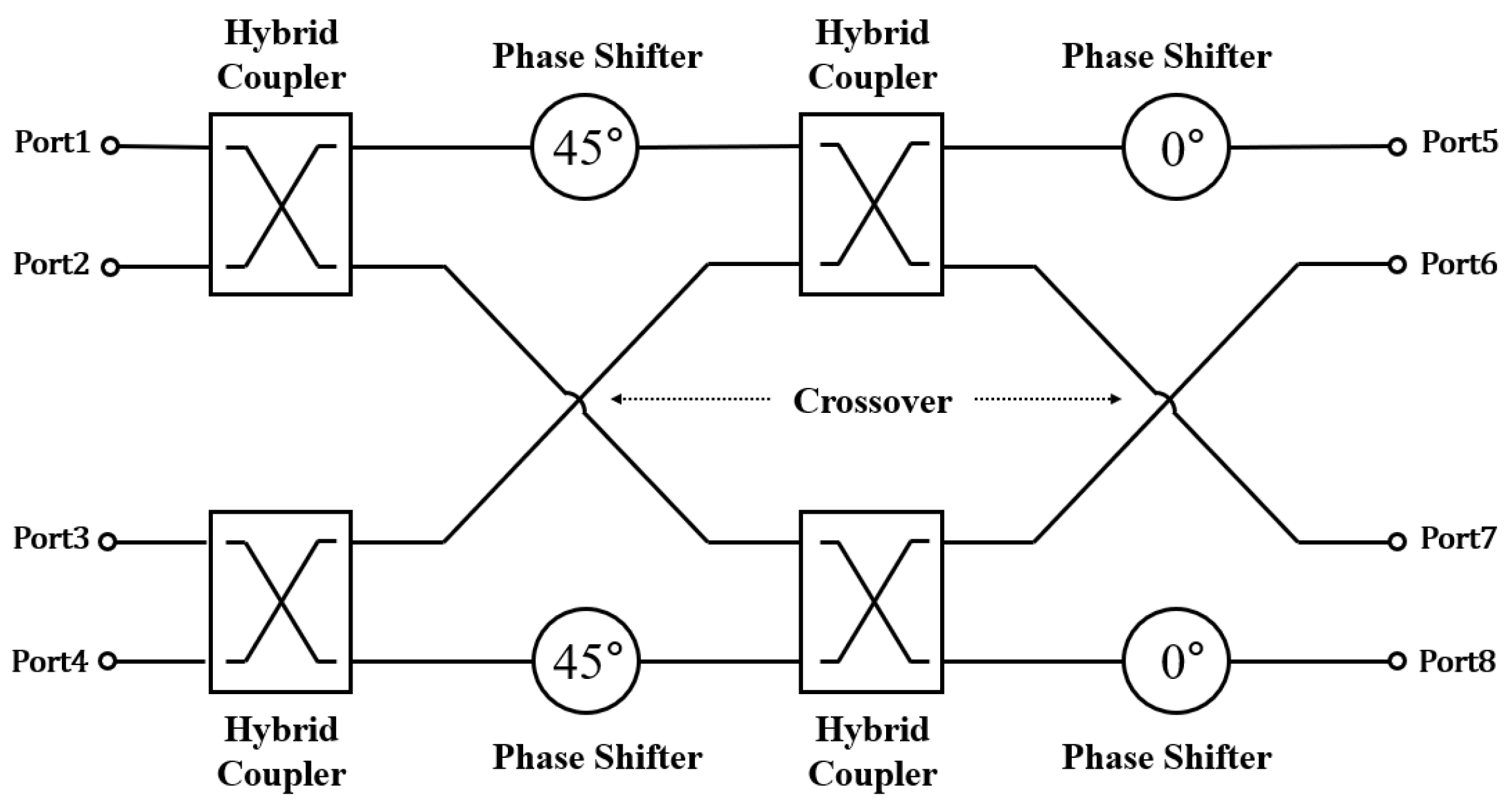
Figure 2 shows the functional block diagram of the proposed 4 × 4 Butler-matrix network used as the analog beamformer unit for the vertical dimension in the MHBF architecture. For each input-port excitation, the network produces a predetermined phase distribution across the output ports, thereby operating a fixed set of beam directions. The Butler matrix is implemented on a single printed circuit board using a Rogers RO4350B substrate with relative permittivity ε r = 3.66 , and loss tangent tan δ = 0.004 . The design process first optimizes the individual passive unit cells, including the hybrid coupler and crossover, in Ansys HFSS, and then integrates them with the required interconnecting lines and fixed phase-shift sections into the complete planar layout.

Design and Layout of the 4 × 4 Butler Matrix

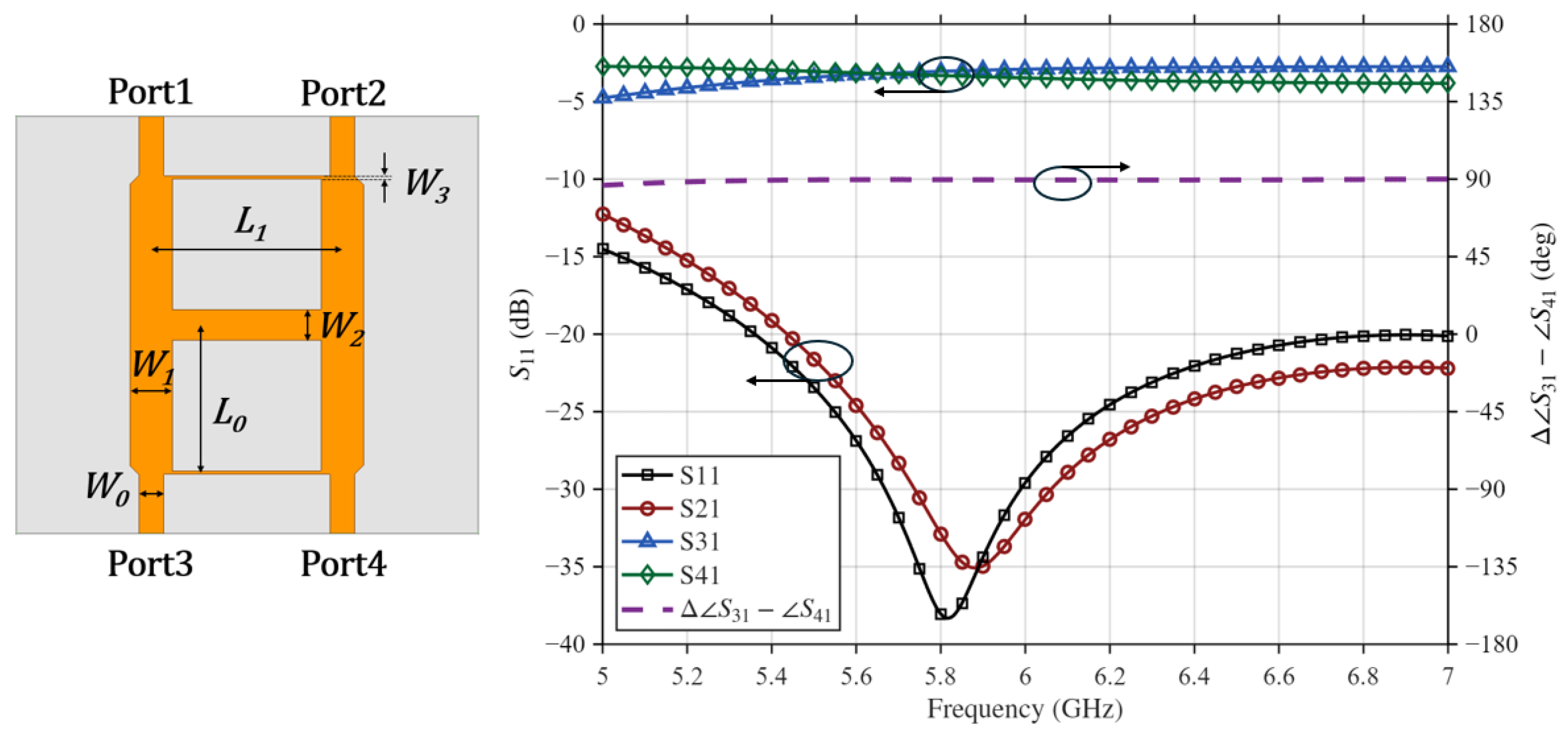
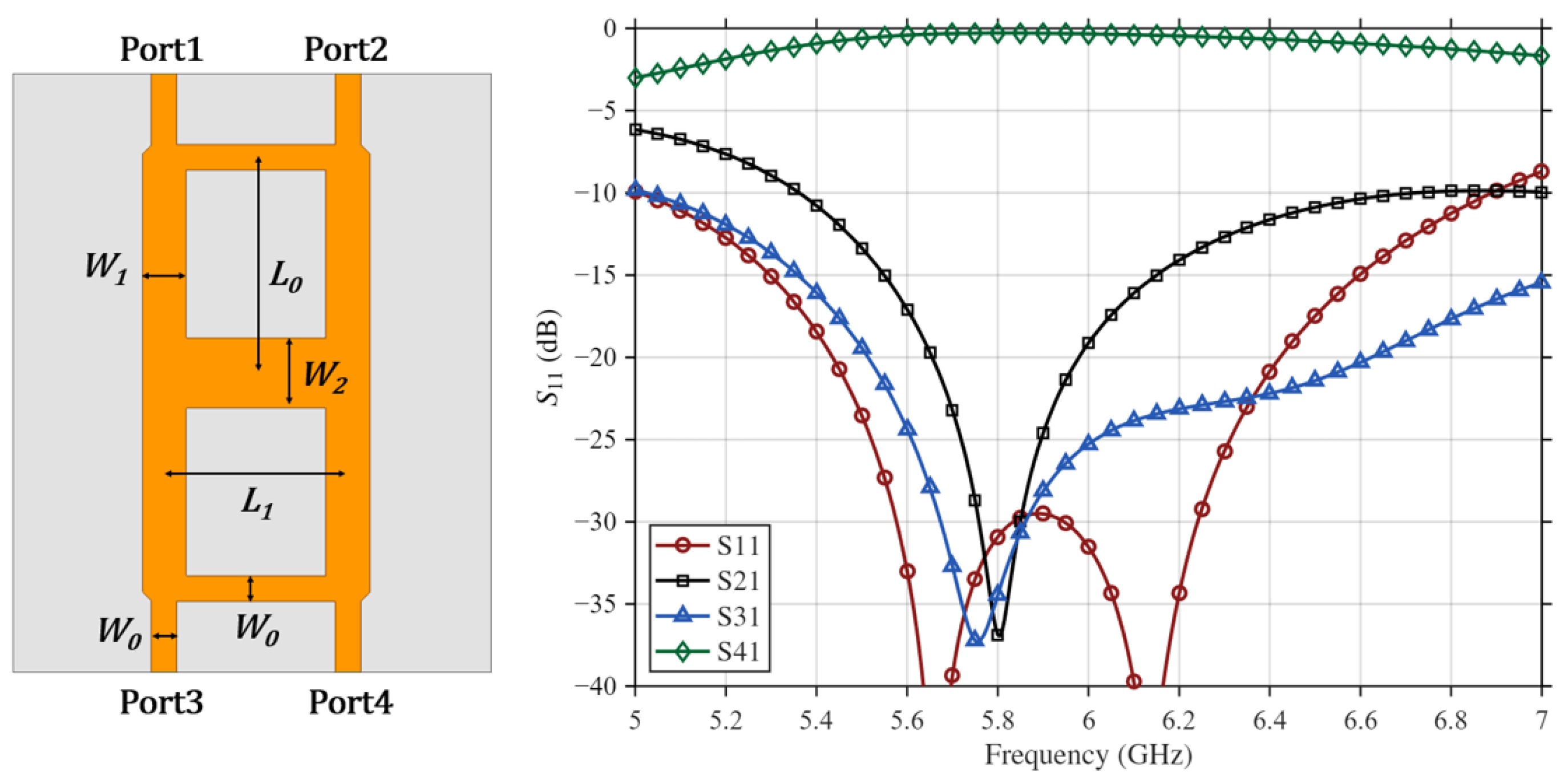
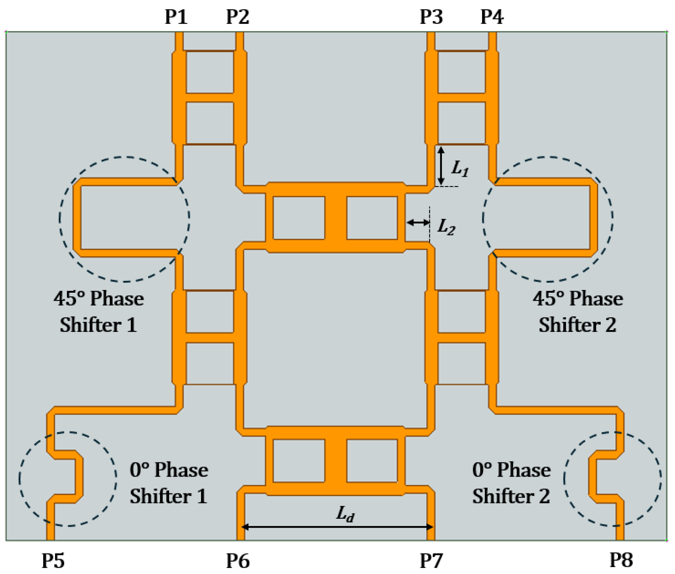
Figure 3 shows the configuration and simulated response of the hybrid coupler. Port 1 serves as the input port, Port 2 is the isolated port, and Ports 3 and 4 are the output ports. At the center frequency of 5.8 GHz, the reflection coefficient S 11 is 38 dB and the isolation represented by S 21 is 32 dB. The transmission coefficients S 31 and S 41 are approximately 3 dB, indicating equal power division. Furthermore, the phase difference between the two output ports is close to 90 , confirming proper quadrature operation. Figure 4 illustrates the configuration and simulated performance of the crossover, where Port 1 is used as the input port. At the center frequency of 5.8 GHz, the reflection coefficient S 11 is 31 dB, and the isolation characteristics represented by S 21 and S 31 are below 34 dB. In addition, the desired transmission coefficient S 41 is 0.3 dB, confirming proper crossover operation. Based on the validated unit cells, the complete 4 × 4 Butler-matrix layout is constructed, as shown in Figure 5. In this layout, Ports 1–4 serve as the input ports, and Ports 5–8 correspond to the output ports. The circuit consists of hybrid couplers, crossovers, interconnecting transmission lines, and fixed phase-shift sections required to realize the prescribed Butler phase relationships. In particular, the 45 and 0 delay-line sections are introduced to maintain the required relative phase offsets at the output ports.
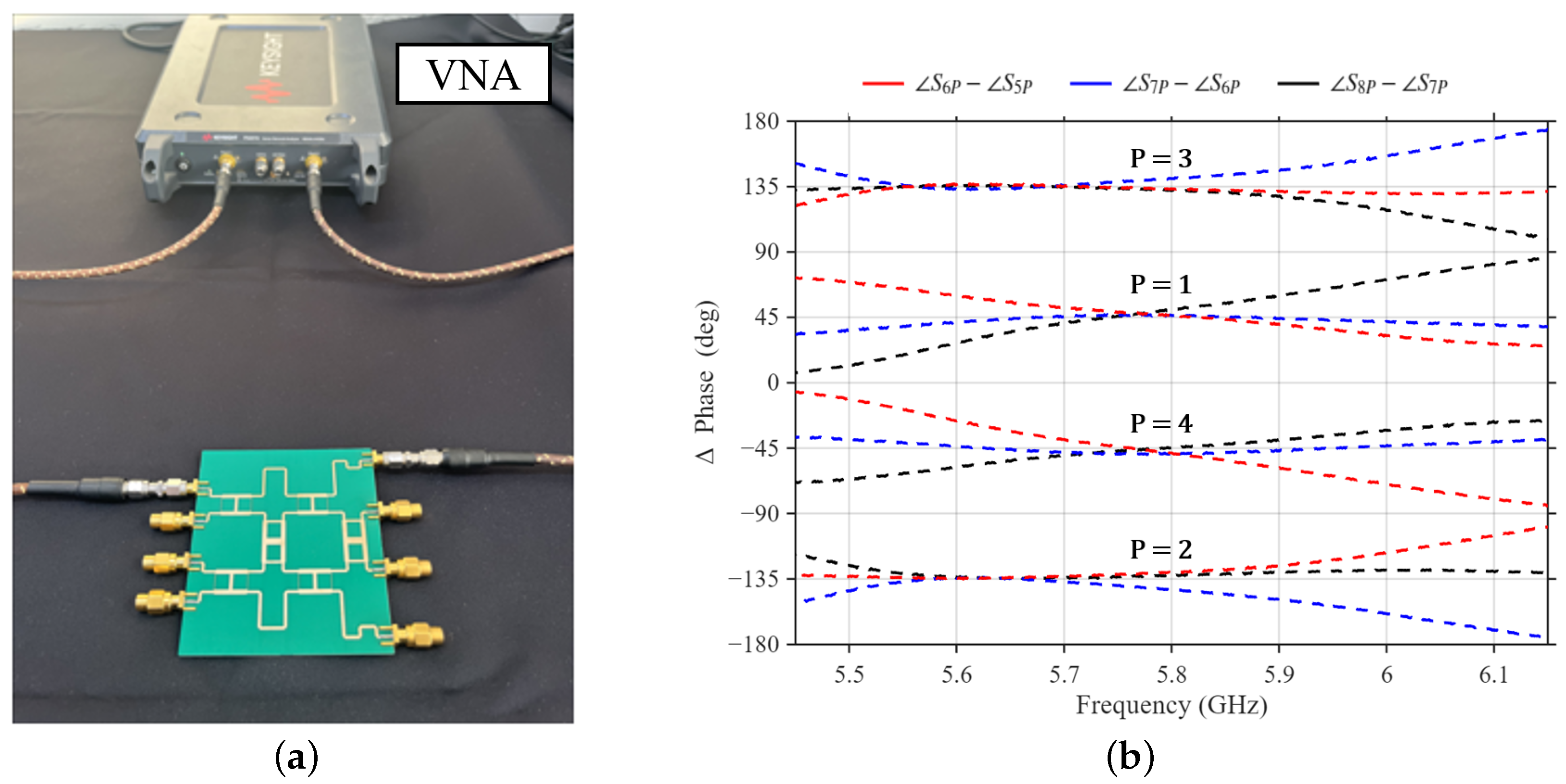
Figure 6a shows the fabricated 4 × 4 Butler matrix and the measurement setup for S-parameter characterization using a vector network analyzer (Keysight P5007A). Figure 6b presents the measured phase differences between adjacent output ports for each excited input port. The measured phase differences closely follow the nominal phase progressions of ± 45 and ± 135 over the frequency range of 5.75–5.85 GHz, with the maximum phase error remaining within 7 .
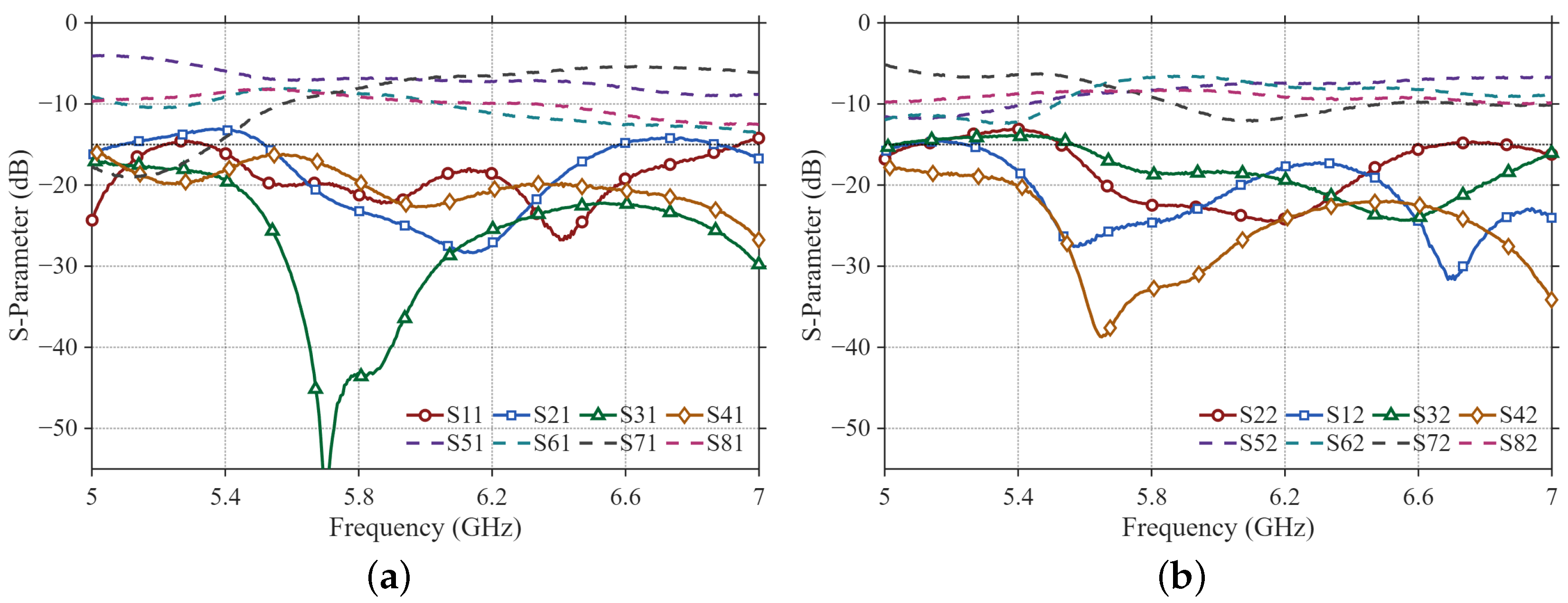
Figure 7 shows the measured S-parameters of the fabricated 4 × 4 Butler matrix for excitations at Ports 1 and 2. The fabricated Butler matrix has a symmetric port configuration, with symmetry between Ports 1 and 4 and between Ports 2 and 3. Since the S-parameter responses of the symmetric ports are similar, the measurements for Ports 1 and 2 are presented as representative results. For Port 1 excitation, the measured reflection coefficient and the coupling levels to the other input ports remain below 15 dB over the frequency range of 5.51–6.58 GHz. At 5.8 GHz, the measured reflection coefficient is 21.3 dB. The measured transmission coefficients from input Port 1 to output Ports 5–8 are 6.84 , 8.07 , 7.62 , and 8.50 dB, respectively. For Port 2 excitation, the measured reflection coefficient and the coupling levels to the other input ports remain below 15 dB over the frequency range of 5.56–6.68 GHz. At 5.8 GHz, the measured reflection coefficient is 22.5 dB. The measured transmission coefficients from input Port 2 to output Ports 5–8 are 8.31 , 6.80 , 8.81 , and 8.30 dB, respectively. These measured results confirm that the fabricated Butler matrix provides suitable input matching, isolation, and output transmission characteristics around the 5.8 GHz design frequency.

4. Prototype Implementation and Experimental Results

4.1. Prototype Configuration and Measurement Setup

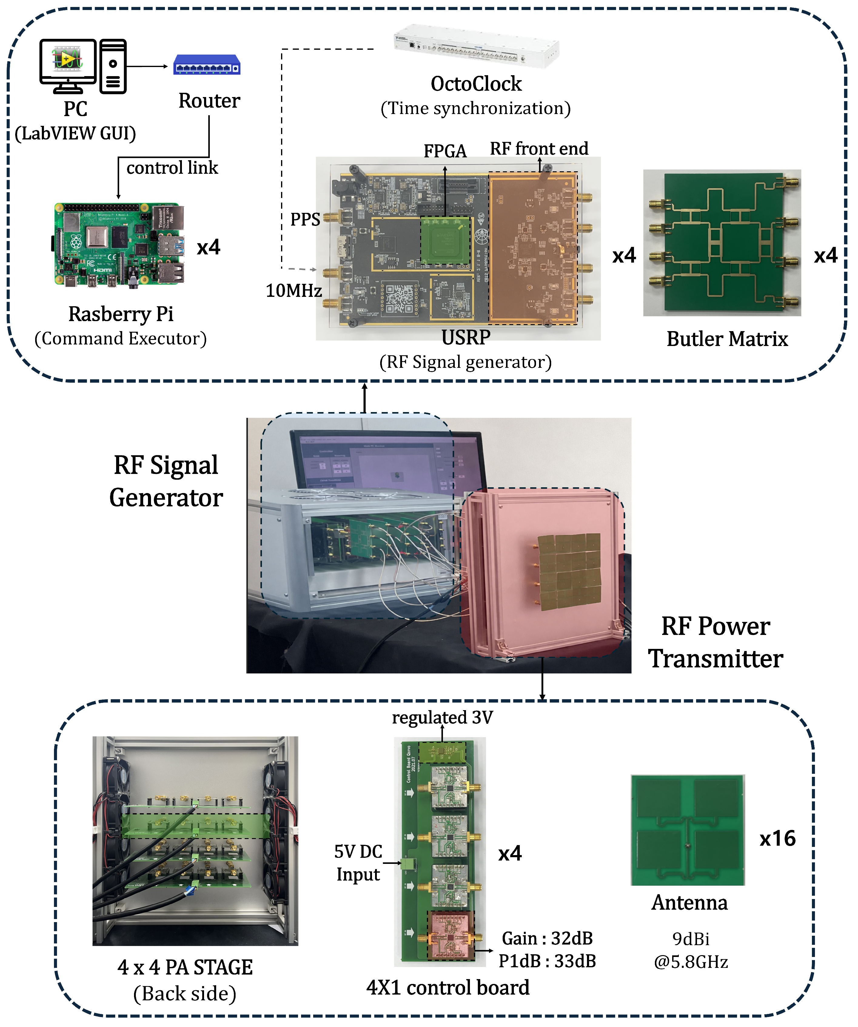
In this section, a 5.8-GHz proof-of-concept prototype of the proposed MHBF architecture was implemented and experimentally validated. Figure 8 presents the implemented prototype, where the overall system is realized using a 4 × 4 array architecture. A PC-based LabVIEW GUI is used to configure the Raspberry Pi 4 Model B microcomputers through a router. Each Raspberry Pi controls a USRP B210 unit. The USRP B210 units are employed as the software-defined radio (SDR) platform for generating digitally precoded multi-tone signals, where adjacent tones are spaced by 10 kHz. To ensure coherent transmission among the SDR channels, a 10 MHz reference signal and a pulse-per-second signal are distributed from a clock distribution module (CDA-2990) to all USRP units. The Butler matrix routes the signal to each element path, where an RF power amplifier (Qorvo QPA9501) is followed by an isolator (UIY UIYCI1522A). The power amplifier provides a gain of 32 dB and a 1 dB compression point of 33 dBm at 5.8 GHz. Patch antennas with a directivity of 9.3 dBi radiate the amplified signals, with inter-element spacings of d x = 38 mm and d y = 41 mm.
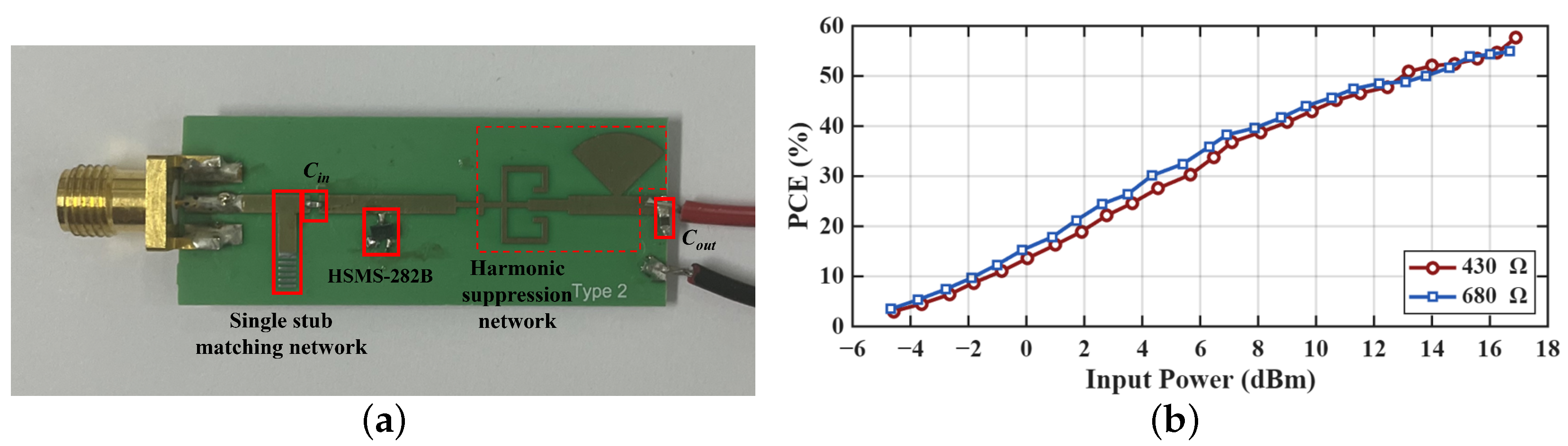
Figure 9 shows the rectifier used for the RF-to-DC conversion measurement and its measured power conversion efficiency (PCE). The rectifier structure was implemented based on the configuration reported in [18]. As shown in Figure 9a, the rectifier consists of a single-stub matching network, an HSMS-282B Schottky diode, a harmonic suppression network, and input/output capacitors. The RF-to-DC conversion characteristics were evaluated under two load conditions of 430 Ω and 680 Ω . The PCE is defined as
PCE = P DC P RF = V 0 2 R L P RF ,
where P RF is the RF input power to the rectifier, P DC is the DC output power delivered to the load, V 0 is the measured output voltage across the load resistor, and R L is the load resistance. The PCE values are expressed in percentage form in the measurement results. Figure 9b shows that the PCE depends on both the RF input power and the load resistance. At the highest RF input power, the PCE values reached 54.9% and 57.6% for the 430 Ω and 680 Ω loads, respectively.
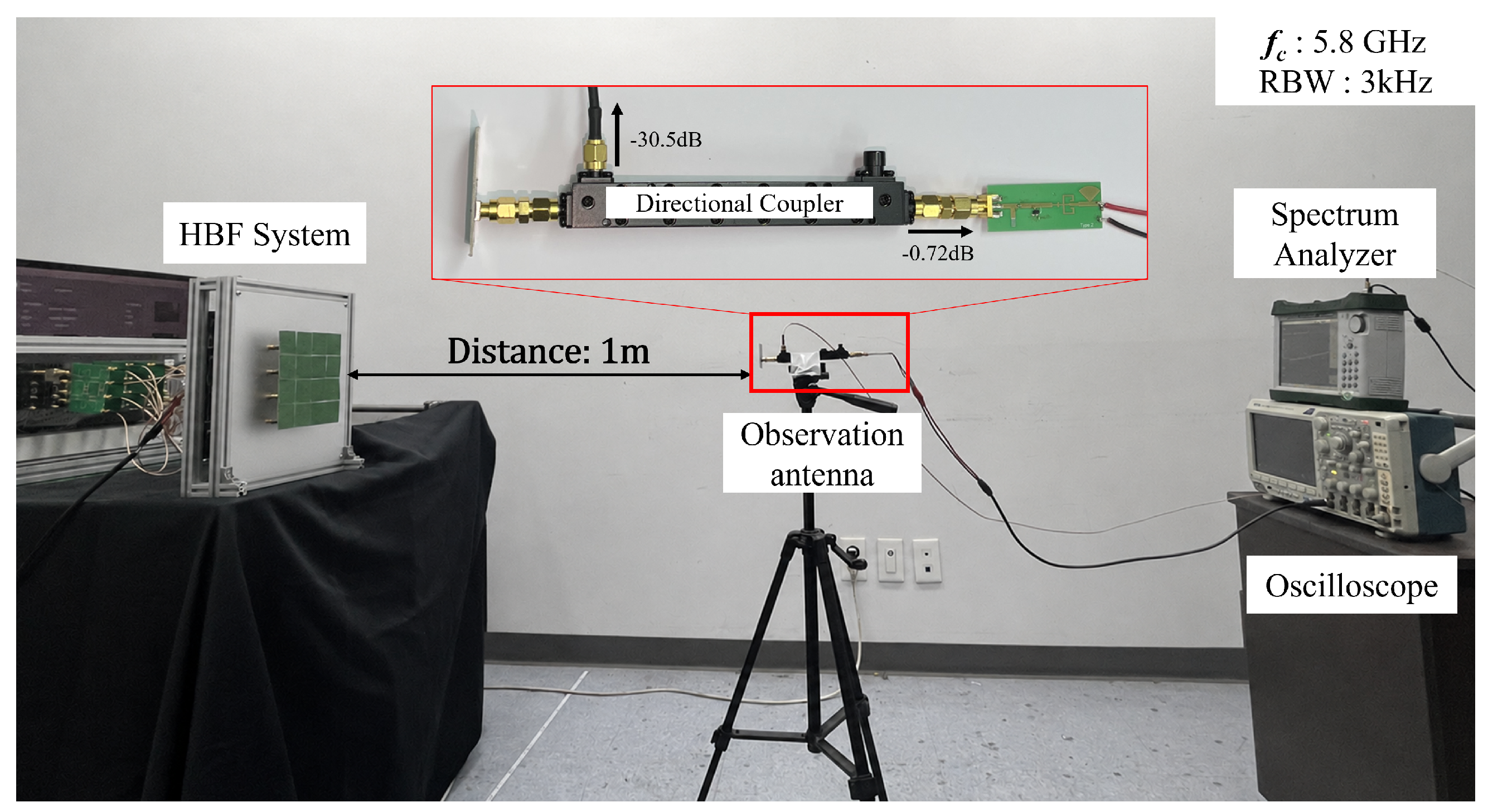
Figure 10 shows the measurement setup for evaluating the multibeam radiation pattern and power-transfer characteristics. For the measurements, the PA output power per element was set to 18.53 dBm, resulting in a total conducted transmit power of 30.57 dBm and an equivalent isotropically radiated power (EIRP) of 51.91 dBm. This power level was determined by considering the peak-to-average power ratio of the generated multitone signal to allow the PA to operate with sufficient linearity margin during multibeam transmission. On the receiver side, the RF signal received by the observation antenna was fed to a directional coupler. The coupled port, with a coupling factor of 30.5 dB, was connected to a spectrum analyzer (Anritsu MS2713E) to resolve the 10 kHz spaced tones and measure the received RF power of each tone with an resolution bandwidth (RBW) of 3 kHz. The received RF power was obtained by compensating for the coupling factor of the directional coupler. The through port of the directional coupler was connected to the rectifier, where the RF signal was delivered with an insertion loss of 0.72 dB before the rectifier input. The output voltage waveform across the load resistor was measured using an oscilloscope (Tektronix MDO3024), and the DC output power was obtained from the mean-square value of the measured voltage waveform. The RF-to-DC conversion performance was evaluated under two load conditions of 430 Ω and 680 Ω .
During the radiation-pattern measurement, the transmit array was fixed while the receiver was rotated at a distance of 1 m with an angular step of 2.5 . At each angular position, the peak received RF power of each tone was recorded, while the receive antenna was aligned to maintain the same polarization as the transmit array. This measurement procedure was used to characterize the multibeam radiation patterns generated by the proposed MHBF architecture.

4.2. Experimental Verification of Multibeam Operation

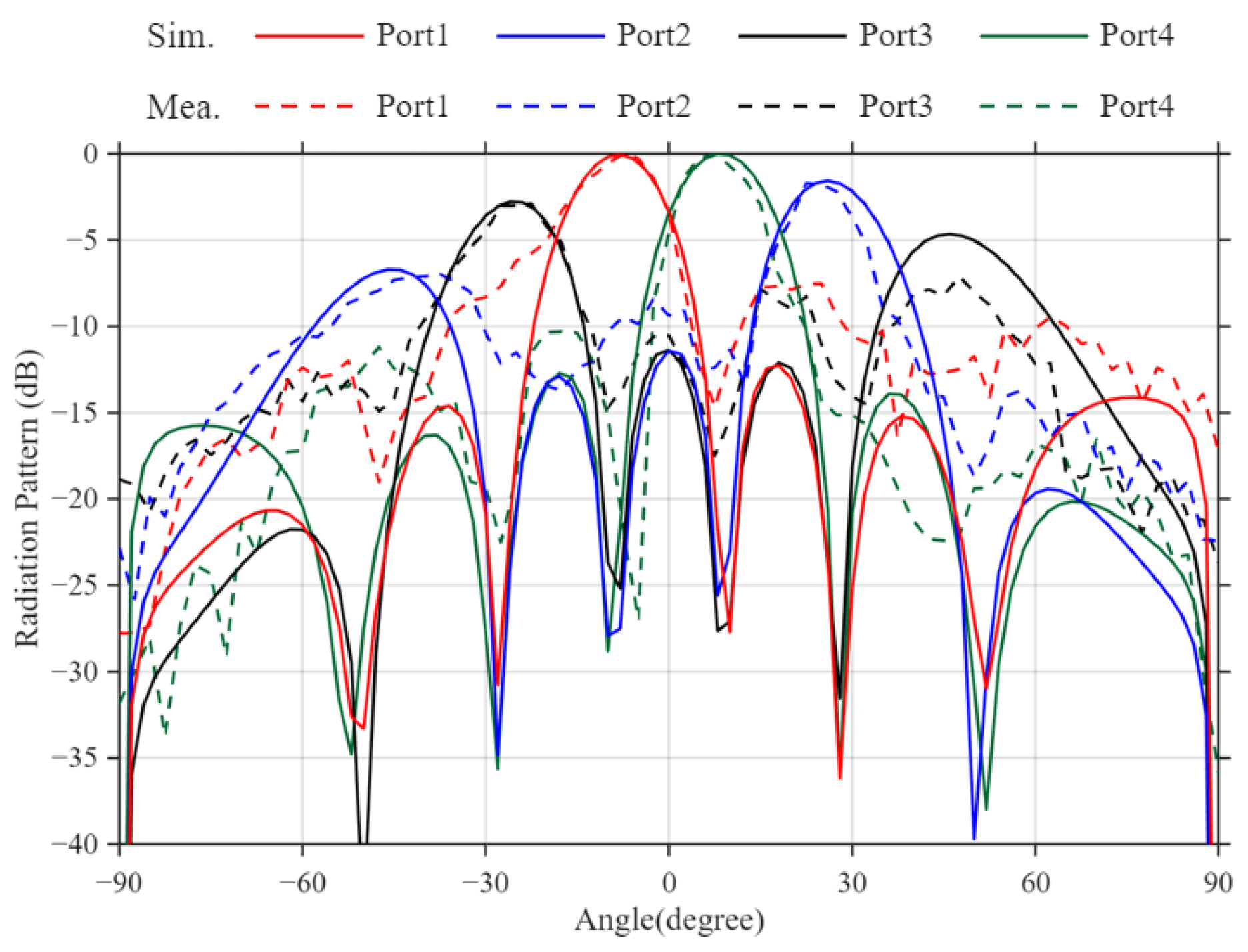
To verify the Butler matrices used for vertical analog beamforming, all four Butler matrices were excited using the same input port. The selected input port was then sequentially changed from Port 1 to Port 4 to generate four distinct single-beam cases. The corresponding simulated and measured radiation patterns are presented in Figure 11. At 5.8 GHz, the measured main-beam directions for Ports 1–4 were observed at 7.5 , 25.5 , 22.5 , and 7.5 , respectively. The measured sidelobe levels (SLLs) for Ports 1–4 were 7.52 , 5.27 , 4.19 , and 10.31 dB, respectively. The maximum differences between the simulated and measured beam directions were within 3.5 . In addition, the measured half-power beamwidths (HPBWs) were 14.9 ± 2.0 .
Table 1 summarizes the RF and rectified DC power results for the single-beam case. For Ports 1–4, the measured RF powers were 12.24, 12.22, 11.96, and 12.03 dBm, respectively, resulting in an average RF power of 12.11 dBm. After RF-to-DC conversion, the average DC powers were 8.87 dBm and 8.96 dBm under the 430 Ω and 680 Ω load conditions, respectively, with corresponding average PCE values of 47.33% and 48.41%.
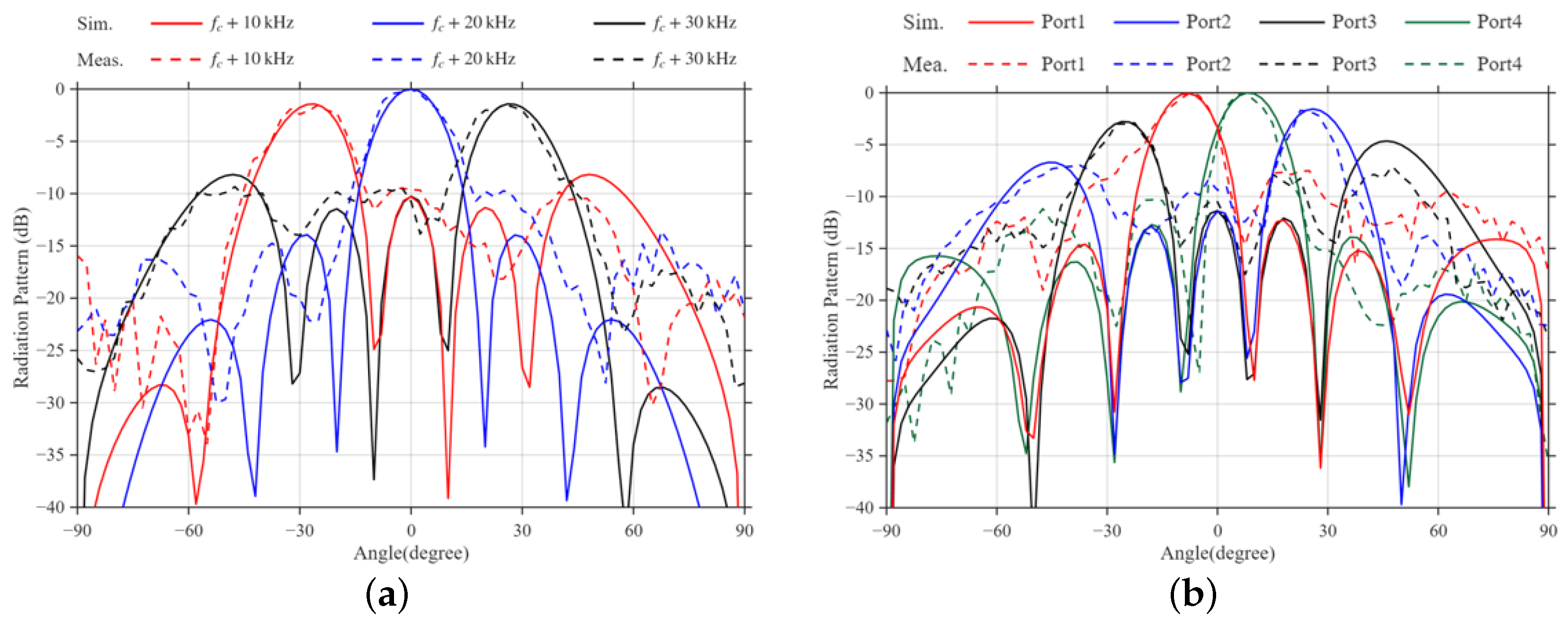
In this measurement, Port 1 was selected as the fixed Butler input port for simultaneous multibeam operation. Thus, the results validate multibeam operation under one selected Butler beam mode, while the Butler-port-dependent beam-mode control was separately verified through the single-beam measurements for Ports 1–4. Figure 12 presents the simulated and measured radiation patterns for the three-beam and four-beam cases. For the three-beam case, the measured peak responses were observed at 25 , 0 , and 25 , respectively. The measured sidelobe levels (SLLs) were 7.98 , 9.71 , and 6.90 dB, respectively. The maximum difference between the simulated and measured beam directions was within 1.0 . In addition, the measured half-power beamwidths (HPBWs) were 19.2 ± 0.7 . For the four-beam case, the measured peak responses appeared at 27.5 , 17.5 , 15 , and 27.5 , respectively. The measured SLLs were 7.99 , 8.91 , 8.71 , and 6.50 dB, respectively. The maximum difference between the simulated and measured beam directions was within 3.5 . In addition, the measured HPBWs were 18.1 ± 1.1 .
Table 2 summarizes the RF and rectified DC power results for the multibeam cases under the 430 Ω and 680 Ω load conditions. In the three-beam case, the measured RF powers were 7.18, 7.45, and 7.23 dBm, resulting in an average RF power of 7.3 dBm. After RF-to-DC conversion, the average DC powers were 2.99 dBm and 3.17 dBm for the 430 Ω and 680 Ω loads, respectively, with corresponding average PCE values of 37.18% and 38.77%. In the four-beam case, the measured RF powers were 6.02, 6.14, 6.11, and 6.08 dBm, resulting in an average RF power of 6.1 dBm. The corresponding average DC powers were 1.16 dBm and 1.53 dBm for the 430 Ω and 680 Ω loads, respectively, with average PCE values of 32.16% and 35.05%.
Compared with the average single-beam RF power, the average RF powers for the three-beam and four-beam cases are lower by approximately 4.8 dB and 6.0 dB, respectively, indicating that the available transmit power is distributed among multiple tones. A similar reduction is observed in the rectified DC output power as the number of simultaneous beams increases. Nevertheless, DC output power was obtained for both multibeam cases under the two load conditions, verifying RF-to-DC conversion in simultaneous multibeam operation and confirming the load-dependent rectifier characteristics.
Table 3 compares the proposed work with previously reported multi-transmitter systems, focusing on multibeam operation and RF chain requirements. The DBF architectures in [12,13,14] require an RF chain for each antenna element. This work proposes an MHBF architecture using fewer RF chains, where simultaneous multibeam transmission is implemented in one dimension and beam steering is enabled in the other dimension.

5. Conclusions

This paper presented an MHBF architecture for wireless power delivery to multiple receivers with a reduced number of RF chains. The proposed architecture decouples beam control into two orthogonal dimensions, enabling simultaneous multibeam formation in one dimension while controlling the beam direction in the other. Specifically, simultaneous multibeam synthesis is realized through baseband multi-tone digital precoding, whereas beam-direction control in the orthogonal dimension is achieved using a Butler-matrix-based analog beamformer. This configuration reduces the number of required RF chains compared with fully digital beamforming, thereby lowering hardware overhead and system complexity. A 5.8 GHz prototype was implemented and experimentally verified. At a distance of 1 m, the average received RF power was 12.11 dBm in the single-beam case, while average received RF power levels of 7.3 dBm and 6.1 dBm per beam were obtained for the three-beam and four-beam cases, respectively. RF-to-DC conversion measurements with 430 Ω and 680 Ω loads further confirmed rectified DC power delivery, showing average PCE values of 37.18% and 38.77% for the three-beam case and 32.16% and 35.05% for the four-beam case, respectively. These results demonstrate that the proposed architecture enables simultaneous MPT to multiple receivers with fewer RF chains.

Author Contributions

Conceptualization, M.H.; methodology, M.H.; software, M.H.; validation, M.H.; formal analysis, M.H.; investigation, M.H.; data curation, M.H.; writing—original draft preparation, M.H.; writing—review and editing, M.H., M.A. and H.K.; visualization, M.H.; supervision, H.K.; project administration, H.K.; funding acquisition, H.K. All authors have read and agreed to the published version of the manuscript.

Funding

This work was supported in part by the Institute of Information and Communications Technology Planning and Evaluation (IITP) grant funded by the Korean Government [Ministry of Science and ICT (MSIT)] under Grant RS-2024-00340504, and in part by the National Research Foundation of Korea (NRF) grant funded by the Government of the Republic of Korea [Ministry of Science and ICT (MSIT)] under Grant RS-2025-16067868.

Institutional Review Board Statement

Not applicable.

Informed Consent Statement

Not applicable.

Data Availability Statement

The data presented in this study are available from the corresponding author upon reasonable request.

Conflicts of Interest

The authors declare no conflicts of interest.

References

  1. Palazzi, V.; Correia, R.; Gu, X.; Hemour, S.; Wu, K.; Costanzo, A.; Masotti, D.; Fazzini, E.; Georgiadis, A.; Kazemi, H.; et al. Radiative Wireless Power Transfer: Where We Are and Where We Want to Go. IEEE Microw. Mag. 2023, 24, 57–79. [Google Scholar] [CrossRef] [Scilit]
  2. Liu, Z.; Li, T.; Li, S.; Mi, C.C. Advancements and Challenges in Wireless Power Transfer: A Comprehensive Review. Nexus 2024, 1, 100014. [Google Scholar] [CrossRef] [Scilit]
  3. Zhu, G.; Dong, J.; Grazian, F.; Bauer, P. A Hybrid Modulation Scheme for Efficiency Optimization and Ripple Reduction in Secondary-Side Controlled Wireless Power Transfer Systems. IEEE Trans. Transp. Electrif. 2025, 11, 6840–6853. [Google Scholar] [CrossRef] [Scilit]
  4. Zhu, G.; Zhang, S.; Deng, Z.; Wang, J.; Li, Y.; Dong, J.; Bauer, P. Extended Hybrid Modulation for Multistage Constant-Current Wireless EV Charging. IEEE Trans. Power Electron. 2025, 40, 10095–10110. [Google Scholar] [CrossRef] [Scilit]
  5. Zhu, X.; Jin, K.; Hui, Q.; Gong, W.; Mao, D. Long-Range Wireless Microwave Power Transmission: A Review of Recent Progress. IEEE J. Emerg. Sel. Top. Power Electron. 2021, 9, 4932–4946. [Google Scholar] [CrossRef] [Scilit]
  6. Shinohara, N. History and Innovation of Wireless Power Transfer via Microwaves. IEEE J. Microwaves 2021, 1, 218–228. [Google Scholar] [CrossRef] [Scilit]
  7. Qin, C.; Chen, F.C.; Xiang, K.R. A 5 × 8 Butler Matrix Based on Substrate Integrated Waveguide Technology for Millimeter-Wave Multibeam Application. IEEE Antennas Wirel. Propag. Lett. 2021, 20, 1292–1296. [Google Scholar] [CrossRef] [Scilit]
  8. Deng, J.Y.; Zhang, Y.; Lin, W. Compact Multibeam Antenna Array Facilitated by Miniaturized Slow Wave Substrate Integrated Waveguide Butler Matrix. IEEE Trans. Antennas Propag. 2024, 72, 9564–9569. [Google Scholar] [CrossRef] [Scilit]
  9. Jiang, M.; Chen, Z.N.; Zhang, Y.; Hong, W.; Xuan, X. Metamaterial-Based Thin Planar Lens Antenna for Spatial Beamforming and Multibeam Massive MIMO. IEEE Trans. Antennas Propag. 2017, 65, 464–472. [Google Scholar] [CrossRef] [Scilit]
  10. Duan, Z.; Yang, X.; Xu, Q.; Wang, L. Time-Division Multiarray Beamforming for UAV Communication. Wirel. Commun. Mob. Comput. 2022, 2022, 4089931. [Google Scholar] [CrossRef] [Scilit]
  11. Sawada, Y.; Shiraki, S.; Matsuda, T.; Hiraguri, T.; Maruta, K.; Kimura, T. Time Division Wireless Power Transfer Using Receiver Grouping. IEEE Access 2024, 12, 109930–109942. [Google Scholar] [CrossRef] [Scilit]
  12. Jiang, Y.; Liu, B.; Li, W.; Wang, X. Retro-Reflective Beamforming to Multiple Targets Based on Time-Reversal for Microwave Power Transmission. In Proceedings of the 2022 IEEE MTT-S International Wireless Symposium (IWS); IEEE: New York, NY, USA, 2022. [Google Scholar] [CrossRef] [Scilit]
  13. Wang, X.; Li, L.; Cui, T.J.; Lu, M. On Differentiation Among Pilot Signals of Multiple Mobile Targets in Retro-Reflective Beamforming for Wireless Power Transmission. Engineering 2023, 30, 55–62. [Google Scholar] [CrossRef] [Scilit]
  14. Yu, Y.; Hong, W.; Jiang, Z.H.; Zhang, H.; Guo, C. Multibeam Generation and Measurement of a DDS-Based Digital Beamforming Array Transmitter at Ka-Band. IEEE Trans. Antennas Propag. 2019, 67, 3030–3039. [Google Scholar] [CrossRef] [Scilit]
  15. Ahmed, I.; Khammari, H.; Shahid, A.; Musa, A.; Kim, K.S.; De Poorter, E.; Moerman, I. A Survey on Hybrid Beamforming Techniques in 5G: Architecture and System Model Perspectives. IEEE Commun. Surv. Tutor. 2018, 20, 3060–3097. [Google Scholar] [CrossRef] [Scilit]
  16. Zhang, J.; Yu, X.; Letaief, K.B. Hybrid Beamforming for 5G and Beyond Millimeter-Wave Systems: A Holistic View. IEEE Open J. Commun. Soc. 2020, 1, 77–91. [Google Scholar] [CrossRef] [Scilit]
  17. Song, X.; Kühne, T.; Caire, G. Fully-/Partially-Connected Hybrid Beamforming Architectures for mmWave MU-MIMO. IEEE Trans. Wirel. Commun. 2020, 19, 1754–1769. [Google Scholar] [CrossRef] [Scilit]
  18. Ahn, M.; Park, J.; An, C.; Ku, H. Multidirectional Microwave Power Transfer With Dual-Side PAPR Control for Improved Power Capability. IEEE Trans. Microw. Theory Tech. 2025, 73, 9773–9782. [Google Scholar] [CrossRef] [Scilit]
Figure 1. Proposed MHBF architecture with decoupled digital multibeam synthesis and analog beam mode control.
Energies 19 02828 g001
Figure 2. Block diagram of the 4 × 4 Butler matrix with hybrid couplers, phase shifters, and crossovers.
Energies 19 02828 g002
Figure 3. Configuration of the hybrid coupler with simulated S-parameters and phase difference between Port 3 and Port 4 ( W 0 = 1.07 , W 1 = 1.83 , W 2 = 1.32 , W 3 = 0.14 , L 0 = 6.4 , L 1 = 4.14 mm).
Energies 19 02828 g003
Figure 4. Configuration of the crossover and simulated S-parameters for Port 3 and Port 4 ( W 0 = 1.07 , W 1 = 1.83 , W 2 = 2.95 , L 0 = 8.06 , L 1 = 7.67 mm).
Energies 19 02828 g004
Figure 5. Layout of the implemented 4 × 4 Butler matrix with fixed delay-line phase shifters ( L d = 25.86 , L 1 = 3 , L 2 = 6 mm).
Energies 19 02828 g005
Figure 6. (a) Fabricated microstrip Butler matrix and VNA measurement setup for S-parameter characterization, and (b) measured output-port phase differences of the 4 × 4 Butler matrix versus frequency for each excited input port.
Energies 19 02828 g006
Figure 7. Measured S-parameters for the 4 × 4 Butler matrix: (a) Port 1 excitation and (b) Port 2 excitation.
Energies 19 02828 g007
Figure 8. Prototype implementation of the proposed multi-tone multibeam MPT transmitter.
Energies 19 02828 g008
Figure 9. Rectifier used for RF-to-DC conversion measurement: (a) rectifier structure and (b) measured PCE under different load conditions.
Energies 19 02828 g009
Figure 10. Measurement setup for multibeam radiation pattern evaluation.
Energies 19 02828 g010
Figure 11. Simulated and measured radiation patterns demonstrating vertical beam steering via the Butler-matrix-based analog beamformer unit for different input ports.
Energies 19 02828 g011
Figure 12. Simulated and measured radiation patterns with the Butler input port fixed ( p = 1 ) under multi-tone digital-precoding excitation: (a) simultaneous three-beam generation and (b) simultaneous four-beam generation.
Energies 19 02828 g012
Table 1. RF and rectified DC power results for the single-beam case.
Port P RF (dBm)430  Ω 680  Ω
P DC (dBm)PCE (%) P DC (dBm)PCE (%)
Port 112.249.0147.509.1048.54
Port 212.228.9847.479.0848.53
Port 311.968.6947.138.7948.24
Port 412.038.7747.228.8748.33
Average12.118.8747.338.9648.41
Table 2. RF and rectified DC power results for the multibeam cases.
CaseTone Frequency
( f c = 5.8  GHz)
P RF (dBm)430  Ω 680  Ω
P DC (dBm)PCE (%) P DC (dBm)PCE (%)
Three-
beam
f c + 10  kHz7.182.8636.973.0538.62
f c + 20  kHz7.453.1937.513.3639.00
f c + 30  kHz7.232.9237.073.1138.69
Average7.292.9937.183.1738.77
Four-
beam
f c + 10  kHz6.021.0531.871.4334.79
f c + 20  kHz6.141.2432.391.6135.25
f c + 30  kHz6.111.2032.261.5735.13
f c + 40  kHz6.081.1532.131.5235.02
Average6.091.1632.161.5335.05
Table 3. Comparison of Multi-transmitter Systems.
Ref[8][9][10][11][12][13][14]This Work
ArchitectureABFABFDBFDBFDBFDBFDBFHBF
MethodButler
matrix
Metamaterial
lens
Time
division
Time
division
Frequency
division
Frequency
division
Frequency
division
Frequency
division
+ Butler
matrix
Control
Dim.
1D1D1D1D1D1D1D2D
SimultaneousXXXXOOOO
Freq.
(GHz)
1528N/AN/A5.85.7524.35.8
Antenna
Array
1 × 4 1 × 7 1 × 4 1 × 8 1 × 4 1 × 4 1 × 15 4 × 4
RF
Chains
N/AN/A4844154
ApplicationCOMM.COMM.MPTMPTMPTMPTCOMM.MPT
Disclaimer/Publisher’s Note: The statements, opinions and data contained in all publications are solely those of the individual author(s) and contributor(s) and not of MDPI and/or the editor(s). MDPI and/or the editor(s) disclaim responsibility for any injury to people or property resulting from any ideas, methods, instructions or products referred to in the content.