Abstract
The asymmetric design of hairpin windings is known as a method for reducing AC losses in electric motors, especially at high frequencies. However, the design of the asymmetric winding is very critical to obtaining the best benefit regarding the efficiency and the thermal performance of the motor. Compared to the state-of-the-art in this paper, deep investigations are carried out to obtain the optimum design of the asymmetric hairpin windings while still employing a conventional manufacturing method. An analytical model is developed to speed up the investigation process, and the results of the analytical model are validated with a finite element method (FEM) model. The conclusions from the analytical investigation are considered in the design of an electric vehicle (EV) motor. The performance of the motor is studied for two different driving profiles to validate the rules of the asymmetric windings design and check the degree of dependency of the design of asymmetric windings on the application. It is proved that using asymmetric design reduces motor losses and improves thermal performance.
1. Introduction
Hairpin windings in AC electric motors have a lot of advantages that lead to an improvement in the performance of electric machines. Compared to the traditional round stranded wires, it is characterized by a higher fill factor [1], higher torque and power density [2], better heat dissipation capability [3], shorter-end windings, which lead to a compact structure, lower DC copper losses due to the greater cross-section area, and the possibility of large-scale automatic production [4].
One of the main problems related to hairpin windings is the uneven current density distribution and high AC losses, especially at high frequencies, resulting from the skin effect and proximity effect [5]. These AC losses cause a decrease in the output power under high-speed (high-frequency) operation [6]. Also, the AC losses cause a difference in value between the DC resistance and the AC resistance of the conductor. As a result, the ratio of the AC resistance to the DC resistance, which is called the resistance factor, can be used to judge the AC losses [7].
Several approaches have been used in order to mitigate the effect of the eddy current losses in hairpin windings. One of the simplest approaches is leaving a space near the slot opening, which is not practical from the point of view of compact design [8]. For the best use of the space near the slot opening, it is advised that using a water jacket inside the slot provides a better cooling option compared to using a housing water jacket [9]. Using this technique, the cooling fluid becomes so close to the conductors and can directly cool them. From all the possible arrangements for the slot water jacket, it is proved that using the water jacket near the slot opening gives the best performance [10]. In this case, the slot water jacket near the slot opening helps partly in the cooling down process of the rotor. Consequently, this decreases the AC losses, reduces the need for high-temperature insulation material, increases the power density, improves the performance of the motor, and increases the efficiency. The challenge related to this method is the reduction in the fill factor [9].
Another approach is increasing the number of conductors per slot [11]. This leads to fewer losses, especially at high frequencies. However, it results in a less robust structure because of the increased number of welded points [12].
Another is using a different material for the winding. As usual, the use of copper for its low resistivity provides high efficiency for traditional winding, as it decreases the DC losses. The strands of the conventional winding mitigate AC losses, which is not the condition of using hairpin winding. As a solution, using a material with higher resistivity would result in the mitigation of AC losses, but it increases the DC losses. A compromise must be fulfilled to keep the same performance or improve it [13]. In [14], it is found that the dimensions of the slot and the construction of the machine affect the level of benefit from using aluminum as an alternative to copper. As a result, care must be taken during the design and manufacturing to use aluminum as a sustainable alternative [15].
Another effective approach is using parallel paths by dividing the conductors near the slot opening in sub-conductors and applying transposition [2]. Conventional hairpin windings are compared to hairpin windings with parallel paths, and it is proved that the use of parallel paths, also called segmented hairpin windings, provides more uniform current density distribution, which leads to lower losses [16]. However, this method also leads to a high number of welded points.
Another approach is using asymmetric conductors with a lower cross-section area near the slot opening and a bigger cross-section area near the yoke [17]. Using an asymmetric hairpin winding reduces the losses at high frequencies and increases the peak output power [18], but the effect over the whole range of operation needs to be investigated as there is a crossover frequency. For any frequency lower than this frequency, the asymmetric bar winding performance will result in more losses than the symmetric bar winding. In [18], a genetic algorithm is used to find the optimum height of each conductor to minimize the losses, which results in various heights for each conductor. The problem related to this idea is the difficulty of manufacturing and the difficulty of application of the winding rules, which will be only applicable using 3D printing [19]. In [20], a height reduction of 20% is proposed to be the best option to offer fewer losses around base speed. However, it is not the best option for other speeds. Also, the investigation was applied to the case of 4 layers per slot and for one machine with specific dimensions.
In this paper, a deeper investigation is carried out for windings that consist of hairpins with two different geometries in the same slots. This ensures conventional manufacturing of hairpins in contrast to the [18,19], which need 3D-printed windings. This paper, compared to previous work from the literature, investigates how to choose the percentage of height reduction and check the validity of the concept for different dimensions, different numbers of layers per slot, and different applications. The investigation is fulfilled using a modified analytical model to obtain a fast indication of the loss’s tendency. The results of the analytical model are validated using finite element (FE) analysis. The analytical model is developed to avoid the problem of long consumed time by the FE simulation to calculate the results at only one frequency. The same approach of using asymmetric hairpin winding is applied to an interior permanent magnet (IPM) EV motor to consider all the phenomena within the machine, such as saturation and the effect of the PM field. To check the validity of the analytical model, the conclusions of the analytical model are considered in the design of the full motor. A thermal study is carried out to investigate the effect of using asymmetric winding on the reduction in the losses and the hotspot temperature of the motor over two different drive cycles.
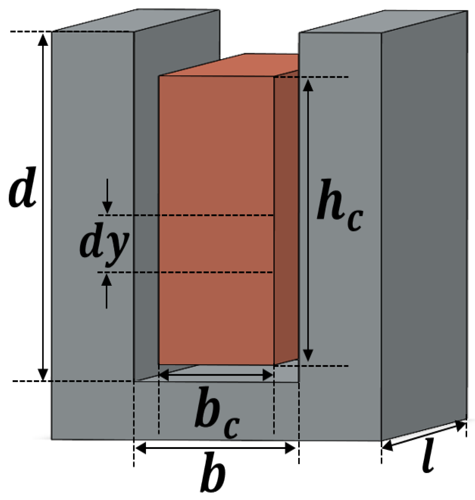
2. Basic Analytical Model
The AC losses become a dominant cause of losses at high frequencies due to the presence of skin effect and proximity effect. The analytical model can efficiently calculate losses over a wide range of frequencies. Figure 1 shows an example of one conductor in an open slot, but the same calculations are extended to include several numbers of conductors within the slot and with different sizes. The difference between the value of the AC losses and the value of the DC losses is an indication of the effect of increasing the frequency on the performance of the motor. The resistance factor is a good measure to judge AC losses. It is a unitless factor that is the ratio between the AC losses and the DC losses [7]:
where are the AC power losses (W) at any specific frequency and DC power losses (W) at frequency zero, respectively. are the AC resistance () and DC resistance (), respectively. The DC power can be expressed as follows:
where is the current passing through the conductor (A), is the electric conductivity (S/m), is the length of the conductor (m), is the width of the conductor (m), is the height of the conductor (m) and is the slot depth (m) as shown in Figure 1. The AC power can be expressed as follows:
where is the current density ( and is the complex conjugate of the current density. can have the following expression:
where are integration constants that are determined by the boundary conditions, and is identified as the depth of penetration that can be expressed using the following expression:
where is the permeability of vacuum, and is the angular frequency (rad/s). is the width of the slot (m). Using (1)–(3) the resistance factor can be identified as follows [16]:
After substitution from (4)–(6) into (7), the resistance factor can be expressed as follows:
Figure 1.
One slot with one conductor.
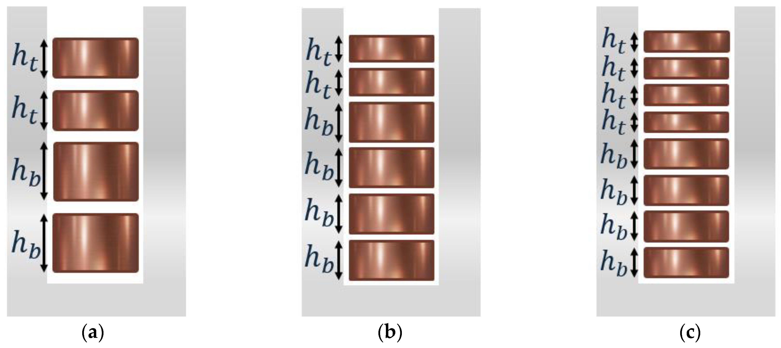
3. Principles of Asymmetric Hairpin Winding
The AC losses are maximum in the layer near the slot opening and decrease in the layers on the way to the yoke. For symmetric hairpin winding with total number of layers per slot (, all the layers have the same height . Reducing the conductor height near the slot opening would result in a reduction in the AC losses in these conductors. The previous procedure would decrease the power losses of the motor. The condition for asymmetric hairpin windings is that a number of layers will have reduced height and a number of layers will have increased height . The number of hairpins with reduced height is chosen according to a rule and two objectives. The rule is keeping the same fill factor of the slot, so the width of the conductors will not be changed, but the change will be only with the heights, ensuring the same total cross-sectional area of the conducting material as follows:
The two objectives are reducing the losses in the windings and keeping manufacturing complexity at a minimum [20].
According to [20], the heights of the hairpins that are near the slot opening will be decreased by and the height of the rest of the hairpins will be increased by . Figure 2 shows how the principles of asymmetric hairpin windings would be applied when the slot contains different numbers of layers. The equations for the top and bottom layers that are used to apply asymmetric hairpin winding are listed in Table 1, which shows the rules that apply to each number of layers per slot.
Figure 2.
Asymmetric hairpin winding for: (a) four layers, ; (b) six layers, ; (c) eight layers, .
Table 1.
Application of asymmetric hairpins for different numbers of layers.
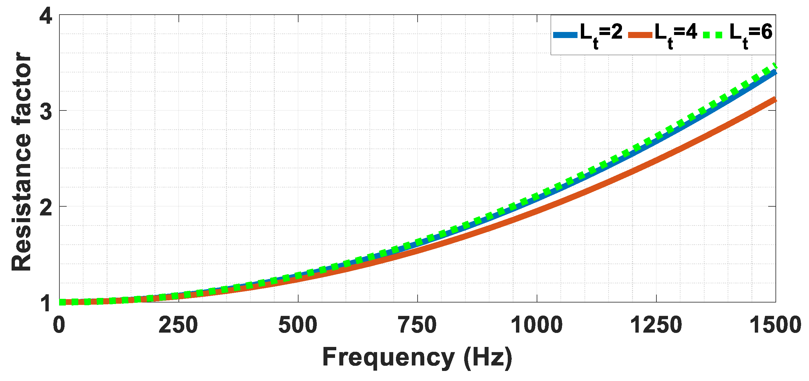
4. Analytical Investigation for Each Number of Layers
Several investigations are needed to find the optimum height reduction for each number of layers per slot. They are introduced in this section.
4.1. Assumptions for the Computation of Optimal Height for Each Layer Group
The AC power losses and the resistance factor are calculated analytically for three cases of the number of layers under different values of height reduction to choose the best value. The total cross-sectional area within the slot is the same for all the cases; the layers within the slot are assigned to the same phase, which is the worst-case condition from the point of view of losses, and the same current density is guaranteed for all cases [21]. So, the DC power losses will be the same in all cases. For 4-layer winding, 150 A will be passed in the winding; for 6-layer winding, 100 A will be passed, and for 8-layer winding, 75 A will be passed. Note that the resistance factor is not affected by the value of the current, but the power losses are affected as in (3) and (7). The basic parameters of conductor width and slot width for all cases of number of layers are introduced in Table 2.
Table 2.
Base Parameters for All Cases.
4.2. The Optimum Height for Each Number of Layers
4.2.1. Four Layers per Slot
The values of and for each value of are calculated according to the equations of Table 1. The power losses per slot ( for a 4-layer winding are shown in Figure 3a. The results of the analytical model are validated at several points with the finite element method (FEM) using Ansys Maxwell. 2022. The third curve for each case of is the interpolation (Intrpl) of the FEM results. Different values of height reduction are introduced in Figure 3b. It can be noticed that the increase in leads to a decrease in the resistance factor at high frequencies. However, there is a crossover frequency. Below this frequency, the increase in leads to an increase in the power losses, which leads to an increase in From the curves of and , it can be observed that for frequencies > 730 Hz, results in lower values of . While for frequencies < 730 Hz, results in higher values of than in the case of as shown in Figure 4a. The same can be observed in Figure 4b for and at . Which means that for operation below , the use of asymmetric winding with results in more losses.
Figure 3.
Four-layer winding at different values of height reduction (: (a) power losses per slot (analytical results and FEM validation); (b) resistance factor .
Figure 4.
Zoom in to show the crossover frequency for (a) and ; (b) and .
The reduction in the loss while using asymmetric windings can be analytically interpreted as in Figure 5 for a frequency of . The blue curve in Figure 5a shows the tendency of the current density distribution to nonuniformity towards the slot opening because of the increasing effect of skin and proximity effect. Where the leakage flux around the bottom part of the slot is higher than the leakage flux around the top of the slot, as the first passes easily through the iron. The use of the reduced height () for the two top layers results in a reduction in the current uneven distribution, which leads to a reduction in the losses as in (3). The reduction in the value of the resistance factor for the two top layers results in a reduction in the resistance factor for the slot, as in Figure 5b.
Figure 5.
Physical effect of using asymmetric hairpin winding: (a) current density distribution in the slot; (b) resistance factor for each layer.
A certain value of for each frequency results in minimum losses. The power losses for symmetric design ( at , height reduction for minimum losses (, the minimum power losses ( at , and the percentage decrease in losses (% at for some values of frequency are introduced in Table 3. It is proved that there is no specific value of that will result in the same percentage decrease in losses for the whole frequency range. The percentage change in losses over the whole frequency range for some values of compared to the symmetric is shown in Figure 6. The positive value of the percentage means a decrease in the losses. The choice of according to this result will depend on the application. If the motor will be used in a race car when very high speeds and high frequencies are required all the time, then higher values of will be the best choice. If the motor will be used within a normal city car, then lower values of will result in a good decrease in losses over the whole frequency range. The negative value of the percentage decrease in losses means that at this frequency, results in an increase in the losses, so care must be taken in the determination of , otherwise choosing for a city car will increase the losses.
Table 3.
Minimum Power Losses at Optimum Height Reduction for Each Value of Frequency for 4-Layer Winding.
Figure 6.
Percentage change in power losses for each value of height reduction ( for 4-layer winding.
4.2.2. Six Layers per Slot
The same analysis that is performed for a 4-layer winding will be repeated in this section for a 6-layer winding to investigate the effect of the number of layers on losses. The values of and for each value of are calculated according to the equations of Table 1, but should be chosen first to decrease the losses. Therefore, the comparison between the two values of is presented in Figure 7a for and . It can be noticed that the use of two top layers with reduced height results in minor losses. To generalize the rule, the same comparison is performed for different dimensions with increased height and decreased width, as shown in Figure 7b, and the same conclusion is obtained. The equations related to from Table 1 are used. The analytically calculated for each case of over the range of operating frequency from 0 to 1500 Hz is shown in Figure 8. It can be noted that after , the decrease in the losses is not noticeable at high frequencies, but on the contrary, the losses are increased at low frequencies.
Figure 7.
Power losses per slot for 6-layer winding for for two different dimensions: (a) ; (b) .
Figure 8.
Resistance factor for 6-layer winding at different values of height reduction (.
For each frequency, there is a specific percentage of height reduction at which the power losses become minimal, as described in Table 4. The value of that causes minimum losses at one specific frequency will not cause minimum losses for the other frequencies. This is the same as concluded for 4-layer winding, but with lower values for here and lower impact on the power losses decrease. Some values of are chosen, and the effect of each value over the whole frequency range is studied as shown in Figure 9. The positive sign of the percentage means a decrease in the losses, and the negative sign means an increase. For a specific , the decrease in losses for 6-layer winding is lower than for 4-layer winding. Also, the frequency at which the losses start to increase is higher for 6-layer winding. This means that a high value of has a negative impact on the losses for low frequencies. To choose a specific value of for the design, two factors must be considered: the value of the loss reduction and the targeted application.
Table 4.
Minimum Power Losses at Optimum Height Reduction for Each Value of Frequency for 6-Layer Winding.
Figure 9.
Percentage change in power losses for each value of height reduction ( for 6-layer winding.
4.2.3. Eight Layers per Slot
As previously carried out for 4-layer and 6-layer windings, the same study is carried out for 8-layer windings. It is found from Figure 10 that reducing the height of the top 4 layers of the 8-layer winding results in fewer losses. The equations related to from Table 1 are used for the calculations of and . The analytically calculated for each case of is shown in Figure 11a. The percentage change in power losses for some values of is shown in Figure 11b. It can be noticed that increasing the number of layers per slot results in a shift of the curves of the percentage decrease in the losses to the right. This means more frequencies under an increase in the losses.
Figure 10.
Resistance factor for 8-layer winding for at height reduction of .
Figure 11.
Eight-layer winding at different values of height reduction (: (a) resistance factor ; (b) percentage change in power losses.
From the comparison of the three cases of the number of layers, decreases with the increase in the number of layers. This results in a decrease in as shown in Figure 12. It can be concluded that the lower the number of layers per slot, the higher the value of that should be chosen to guarantee a decrease in the losses over the whole frequency range. It can be observed that using 4-layer winding with leads to close or lower values of compared to 6-layer winding. That results in a decrease in the losses with a reduction in the welded points, leading to higher reliability.
Figure 12.
Resistance factor for various numbers of layers winding at: (a) ; (b) ; (c) ; (d) .
5. Parametric Study of All the Dimensions and the Effect on Height Reduction
In this section, a parametric study of all the dimensions with the effect on height reduction is carried out. The width of the slot , the width of the conductor and the height of the conductor are changed. The analysis is introduced for a 4-layer winding, but it is the same for a 6-layer and 8-layer winding.
5.1. Changing Conductor and Slot Width
Only and are changed in Table 5, but all the other parameters are still the same. Decreasing the conductor width to slot width ratio leads to a decrease in as shown in Figure 13a. In general, increasing the conductor width while keeping the same current leads to a decrease in the power losses starting from DC power losses because of increasing the area of the conductor. In this analysis the slot width is changed as well. The percentage decrease in losses is calculated at and for each width value as shown in Figure 13b. Despite the difference in the widths, the percentage decrease in losses is so close for each height reduction. It can be found that the percentage decrease in the losses is approximately independent of the current density.
Table 5.
The Changed Values of and .
Figure 13.
For various values of and : (a) resistance factor at ; (b) percentage decrease in power losses at and .
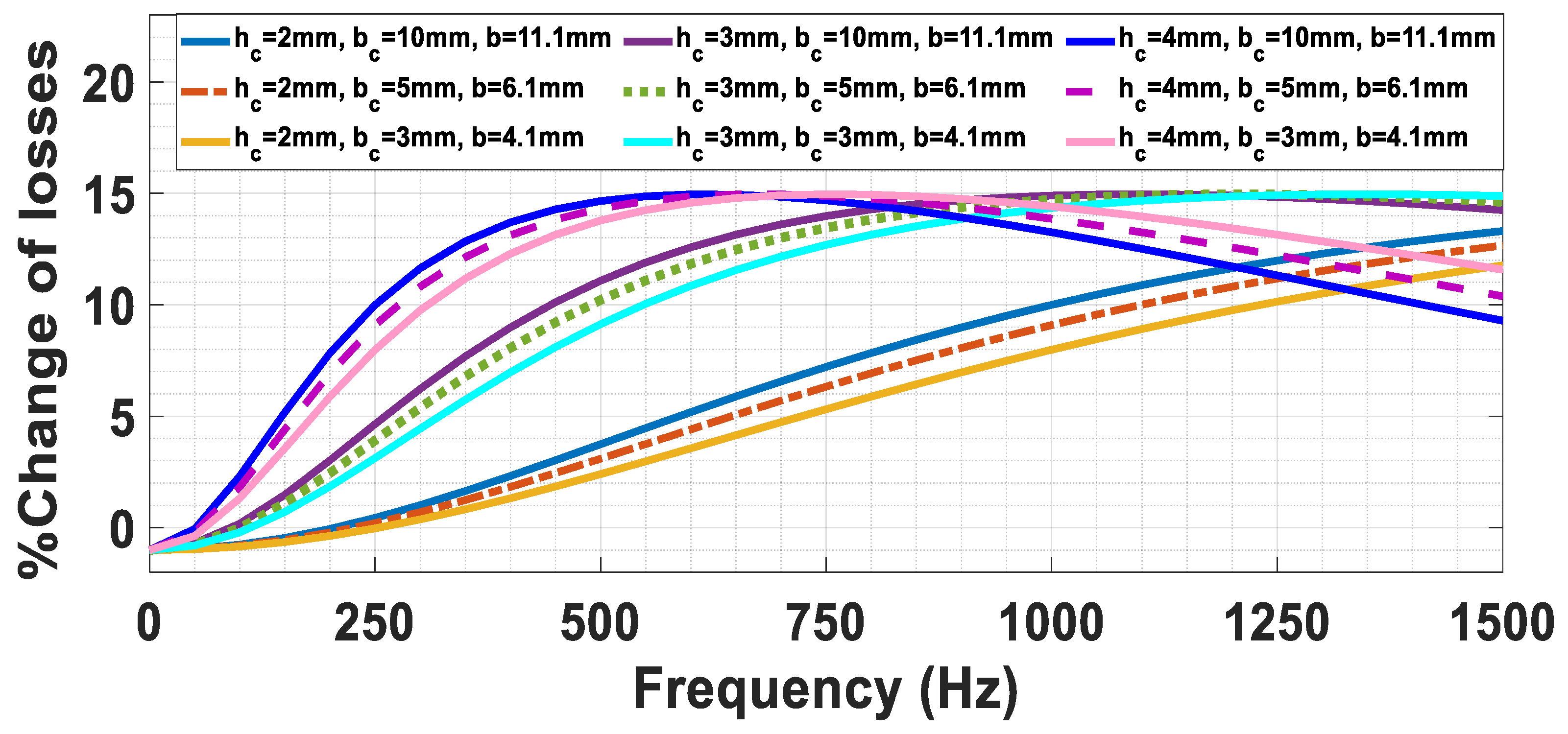
5.2. Changing Conductor Height and Width and Slot Width
In this investigation, the , and form Figure 1 are changed. The initial DC power losses are kept the same for each case by changing the current. As shown in Figure 14, the change in the height results in a major difference in the power losses. The percentage decrease in losses differs massively because of the change in the value of the height as shown in Figure 15. It can be concluded that the change in the width has a minor effect on the percentage decrease in the losses, while changing the height has the major effect. Also, for all the widths and heights for a specific value of , there is a maximum value of percentage reduction in losses that they all reach but at different frequencies.
Figure 14.
Resistance factor for various values of , and at : (a) ; (b) ; (c) ; (d) .
Figure 15.
Percentage decrease in power losses for various values of , and at height reduction .
5.3. Changing All Dimensions but with the Same Conductor Cross-Sectional Area
In this section, and are changed. The current is the same, and the cross-sectional area of each conductor is kept the same by changing the as declared in Table 6. From Figure 16, it is concluded that the small value of the ratio results in lower losses, especially at high frequencies.
Table 6.
The Changed Values of and Keeping the Same Conductor Cross Section Area.
Figure 16.
Resistance factor . for various values of , and , keeping the same conductor cross area.
5.4. Changing the Conductor Dimensions with Respect to the Slot Dimensions
In this section, is changed while keeping and the same for all the cases. As shown in Figure 17, decreases with the reduction in the . The lower AC losses are obtained at a low value of . The low value of for the same conductor height means a lower fill factor, which means losing one of the most important advantages of hairpin winding. As a result, the conclusions that come from these curves cannot be followed to make the best use of the volume of the machine.
Figure 17.
Resistance factor for various values of , keeping the same .
The following conclusions can be obtained from the previous investigations that can be taken as design rules for the motor with asymmetric hairpin winding:
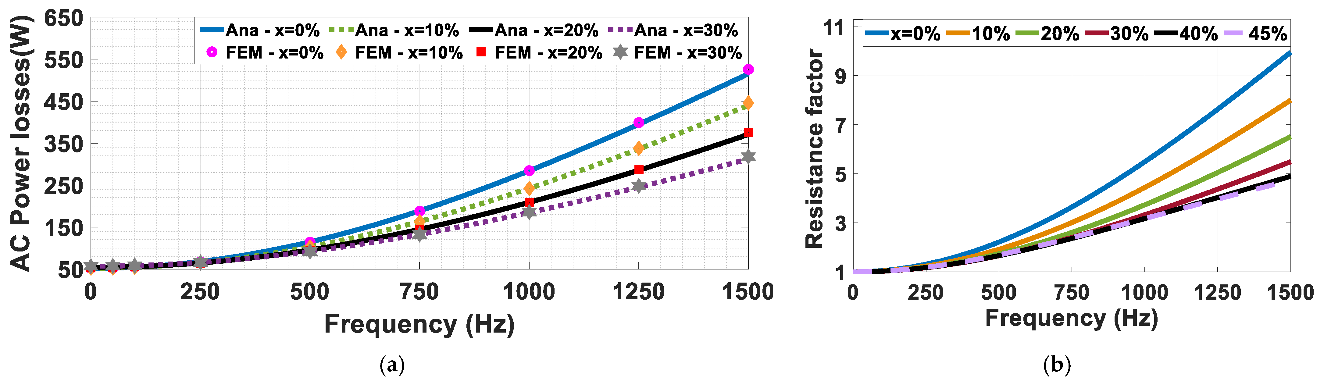
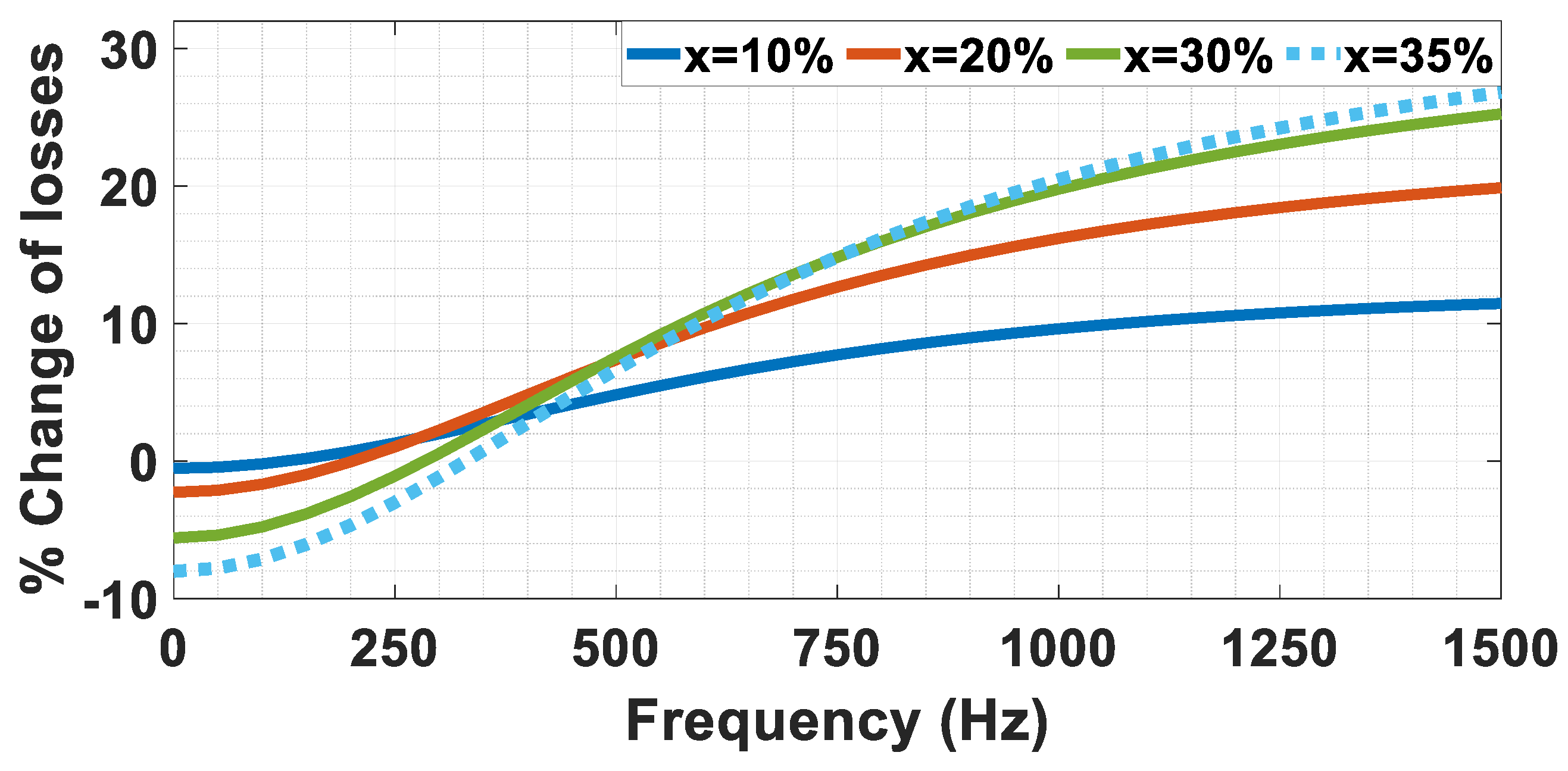
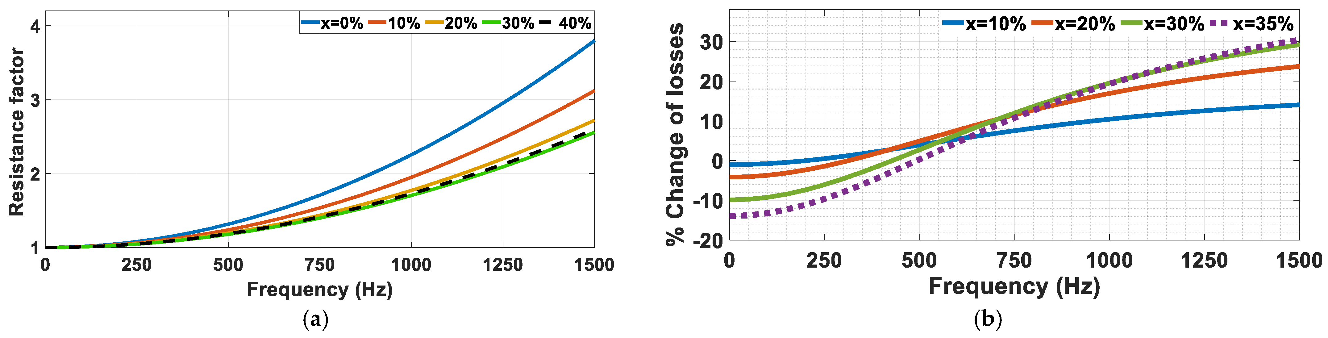
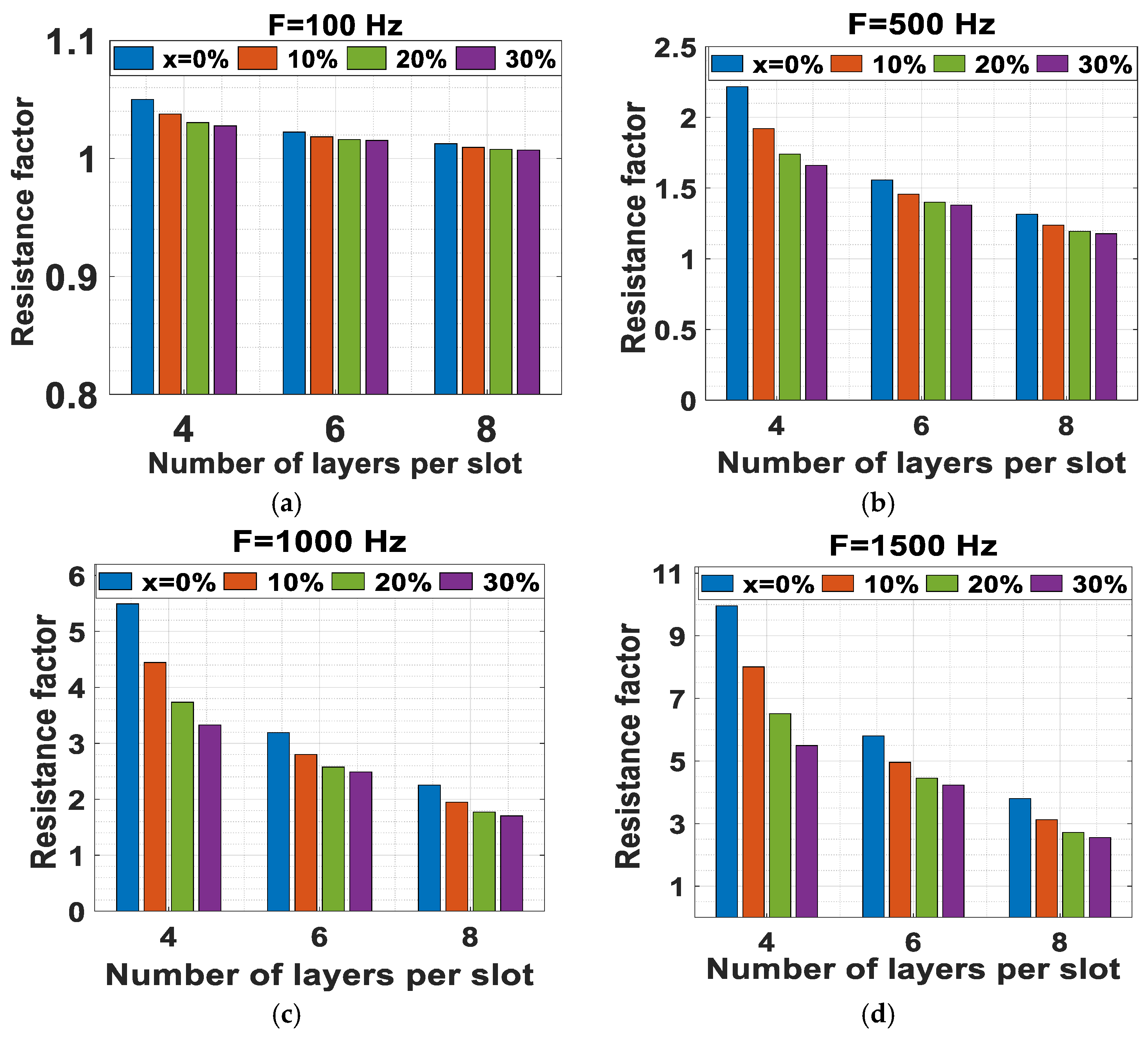
- The increase in the percentage of height reduction results in a decrease in power losses, especially at high frequencies, while it has a minor reverse effect at low frequencies.
- The lower the number of layers, the higher the value of that is required to achieve lower losses, as the change in the conductor height has a major effect on the percentage decrease in losses.
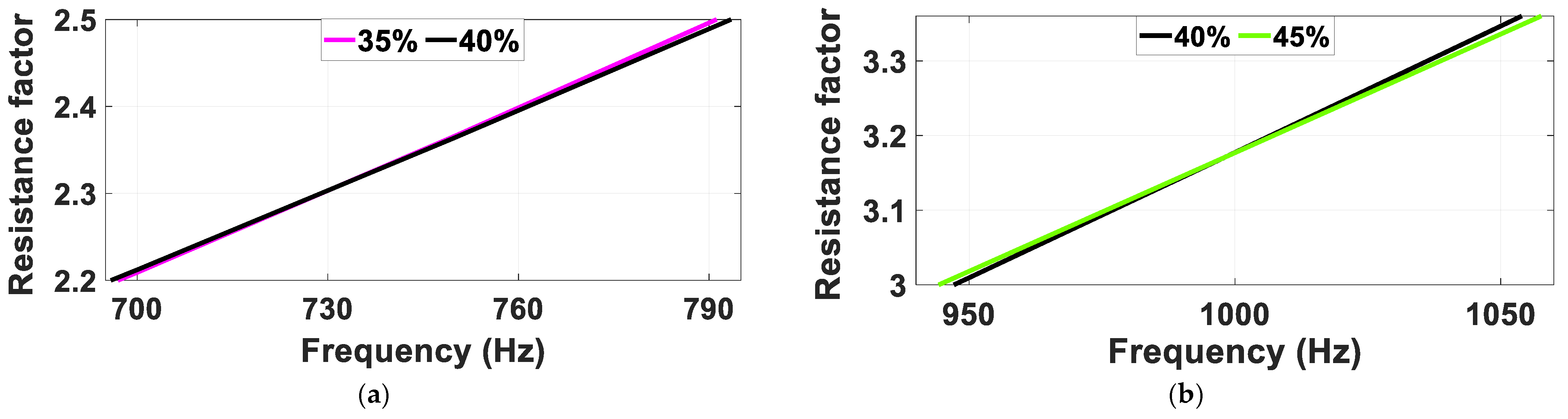
- It is found that a value of results in a decrease in the losses over the whole frequency range.
- For race car applications, can be chosen to have a high value () as higher speeds are required through the whole period of the driving cycle.
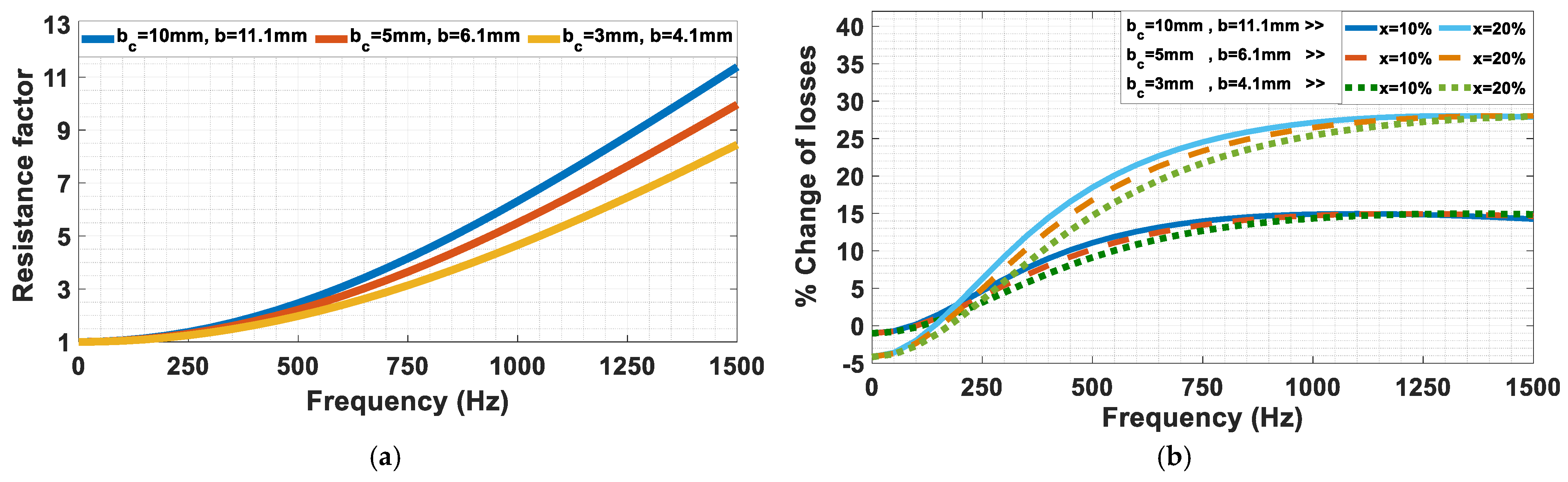
- The percentage decrease in the losses is approximately independent of the conductor width or the current density for a specific value of .
- The lower the ratio , the lower the losses, especially at high frequencies.
- The lower the ratio of , the lower the losses, but this is at the account of the fill factor.
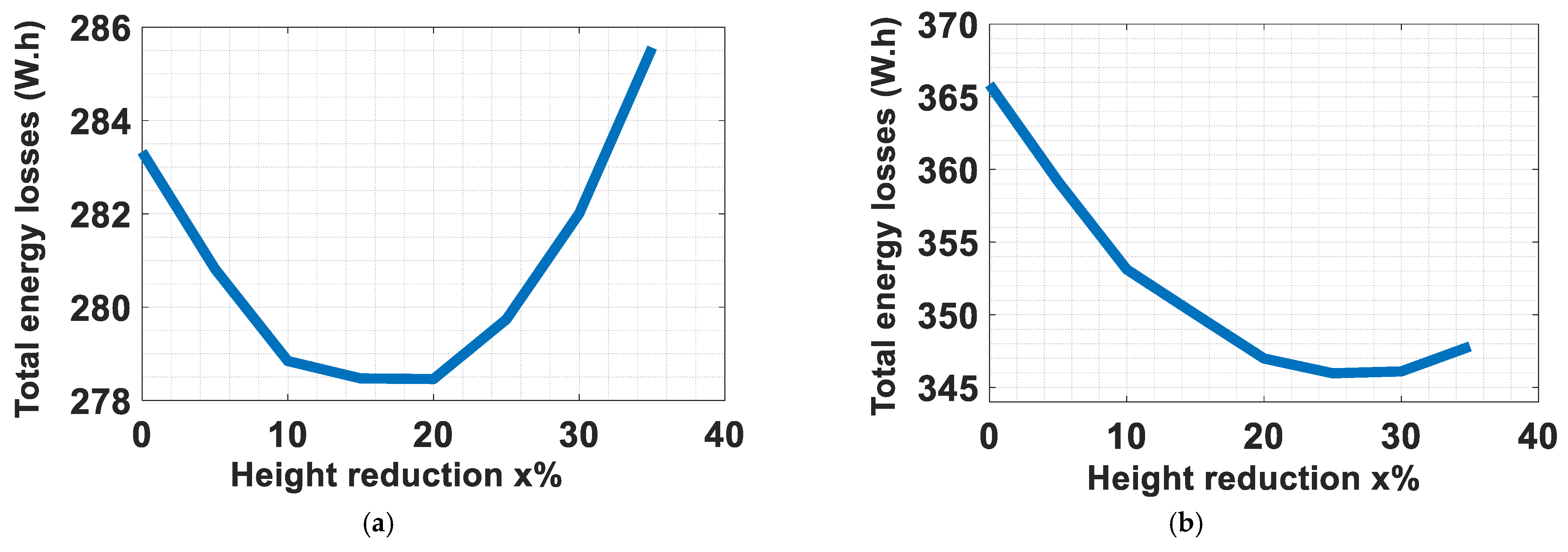
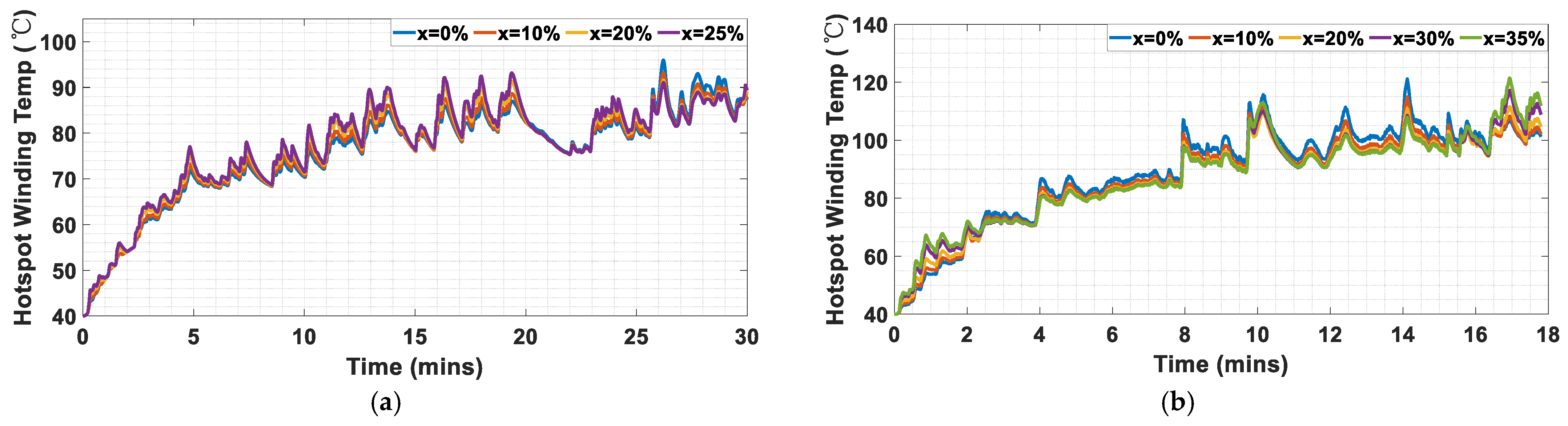
6. Thermal Impact of Asymmetric Windings: Electric Vehicle Motor Case Study
The previous rules come from the analytical investigation for one slot. That is why a full simulation for a full motor is important to validate the conclusions of the analytical model and to include all the phenomena and nonlinearities related to motor operation. To illustrate the effect of asymmetric hairpin windings, we implemented them for a specific case study: a 150 kW, 16-pole interior permanent magnet (IPM) EV motor as follows:
- A 6-layer winding is chosen that leads to intermediate welding points.
- With a slot depth ), a conductor height ) is practical from the point of view of the losses and the value of .
- A high value of is chosen to guarantee a better fill factor.
- A low value of is chosen to decrease the losses as much as possible.
A 3D steady-state thermal model of the motor is carried out using MotorCAD.2023.1.2. The simulation is operated for different operating points of speed and load when the ambient temperature is 40 °C. The motor is cooled using a spiral-type housing water jacket. Additionally, a 50/50 Ethylene Glycol + Water (EGW) Mix is used as a coolant with thermal conductivity of and a pressure of 2441 Pa. The flow rate of the coolant is from the front of the motor to the end. The cross-sectional area of the spiral channel is with a total length of . In Figure 18, the asymmetric hairpin winding is used with different values of height reduction, and the effect on the temperature of the coils is presented. The motor at this simulated operating point has full load torque and a speed of 15,000 rpm, which is related to a frequency of 2000 Hz. It can be noticed that the use of asymmetric winding results in a decrease in the temperature, especially at the hotspot near the slot opening. The temperature decrease is observable until . For , the temperature starts to increase.
Figure 18.
The temperature decreases with asymmetric winding at 2000 Hz: (a) ; (b) ; (c) ; (d) ; (e) .
In Figure 19, the speed of the motor is halved to 7500 rpm—corresponding to a frequency of 1000 Hz—and operates again at full load. The use of an asymmetric winding also results in a decrease in the winding temperature till . The temperature decrease is less spectacular than at 2000 Hz.
Figure 19.
The temperature decreases with asymmetric winding at 1000 Hz: (a) ; (b) ; (c) .
For low frequencies such as 100 Hz (750 rpm), the use of asymmetric windings is not very useful. Figure 20 shows that asymmetric windings result in a minor increase in the winding temperature. However, there will be no negative impact on insulation health as the temperature is generally low, so this effect can be neglected.
Figure 20.
The temperature minorly increases with asymmetric winding at 100 Hz: (a) ; (b) ; (c) .
The asymmetric winding results in a decrease in the AC power losses and the resistance factor, mostly at high frequency, as shown in Figure 21.
Figure 21.
Resistance factor for the EV motor (MotorCAD simulation).
These results, which take into account all the nonlinearities within a machine, validate the conclusions of the analytical investigation, as there is no specific that is suitable for all frequency ranges.
All the previous results are carried out for one specific operating point. However, it is important to study the effect of using the asymmetric hairpin winding for a drive cycle, as the choice of the value of is application-related. Two different drive cycles are studied to investigate the effect of the application on the choice of the value of : the WLTP class 3 drive cycle, which represents the common vehicles driven in Europe, and the Artemis Motorway 150 drive cycle, which represents vehicles always on the highway, are shown in Figure 22.
Figure 22.
The drive cycles: (a) WLTP class 3; (b) Artemis Motorway 150.
The total power loss, which is the difference between the input power and the output power, over the whole drive cycle is shown in Figure 23 for the two types of drive cycles. It can be observed that the motor of a car moving with the WLTP class 3 drive cycle requires a lower value of for the design of the asymmetric winding. Subsequently, using another drive cycle with very low values of speed (frequencies), such as in very crowded cities, requires a lower value of . The save in energy for over a distance of 12,000 km for the WLTP class 3 drive cycle, when is used, is 971 W·h, while the save in energy over the same distance for the Artemis Motorway 150 drive cycle, when is used, is 4160 W·h. That is why using asymmetric winding with applications that require high speed (high frequency), such as race cars, is more efficient.
Figure 23.
Total power losses over the whole drive cycle for different : (a) WLTP class 3; (b) Artemis Motorway 150.
From the thermal point of view, a transient simulation is carried out to present the temperatures over the drive cycles. The hottest spot of the motor is the winding, especially the top layer near the slot opening. The hotspot winding temperatures over the whole two drive cycles for different values of are shown in Figure 24. A zoom-in shown in Figure 25 is focused on the period of the highest temperature, which has the highest thermal stress on the winding insulation over long-term operation. Specifically, for Artemis Motorway 150 in Figure 25b, the temperature decrease is about . The temperature decreases with the increase of until a certain limit. These results comply with the results of the total power losses.
Figure 24.
Hotspot winding temperature over the whole drive cycle for different : (a) WLTP class 3; (b) Artemis Motorway 150.
Figure 25.
A zoom-in of Figure 24 to show the effect of on the hotspot temperature: (a) WLTP class 3; (b) Artemis Motorway 150.
A general conclusion of the previous results for this specific case study is that a value of can give good results for both drive cycles, but this is under the condition that the maximum speed is translated to high frequency. Otherwise, if the motor can work at very high speeds with a low operating frequency due to a low number of poles, this value of cannot be guaranteed to give the best values.
As a result, some factors should be considered before the choice of the optimum value of as follows:
- The design of the motor decides the ratio between the speed and the frequency.
- The design of the gear system decides the ratio between the EV speed and the motor speed.
- In which application is the EV used? City car, highway truck, race car, etc.
7. Conclusions
Great benefits regarding motor losses and thermal stress can be obtained by using optimally designed asymmetric hairpin winding. It is advised to use a low number of layers with a high value of height reduction to obtain lower losses and higher reliability with lower welded points. The design of asymmetric winding is application-dependent. That is why the application (which decides the majority of motor speeds over the drive cycle), the gear system, and the relation between the speed and the frequency of the motor are three important factors to be considered for the design of the asymmetric winding. These factors are all translated into the operating frequency of the motor. It is advised that any value of height reduction less than 10% will be suitable for most applications and will result in good loss reduction. For applications that require a high-frequency motor operation, such as a specific case of the Artemis Motorway 150 drive cycle, a height reduction of 25% will guarantee optimum loss reduction and a temperature decrease at the hotspot of about 13 °C. Therefore, it is advised to use asymmetric winding for electric race cars. It is proved that using the asymmetric hairpin winding decreases the hotspot temperature, which protects the insulation of the winding over long-term operation. Experimental validation is applicable after the manufacturing process of hairpin winding with three different heights for two motors with the same dimensions.
Author Contributions
Conceptualization, S.M.I., M.N.I. and P.S.; methodology, S.M.I. and P.S.; software, S.M.I. and P.S.; validation, S.M.I. and P.S.; writing—original draft preparation, S.M.I.; writing—review and editing, S.M.I., M.N.I. and P.S.; visualization, M.N.I., E.M.R. and P.S.; supervision, M.N.I., E.M.R. and P.S. All authors have read and agreed to the published version of the manuscript.
Funding
This research was funded by the Special Research Fund of Ghent University, Belgium (BOF 01W00222).
Data Availability Statement
The contributions presented in the study are included in the article.
Conflicts of Interest
The authors declare no conflicts of interest.
References
- Zhao, Y.; Li, D.; Pei, T.; Qu, R. Overview of the rectangular wire windings AC electrical machine. CES Trans. Electr. Mach. Syst. 2019, 3, 160–169. [Google Scholar] [CrossRef]
- Pastura, M.; Notari, R.; Nuzzo, S.; Barater, D.; Franceschini, G. AC losses analysis and design guidelines for hairpin windings with segmented conductors. IEEE Trans. Transp. Electrif. 2023, 10, 33–41. [Google Scholar] [CrossRef]
- Ghahfarokhi, P.S.; Kallaste, A.; Podgornovs, A.; Cardoso, A.J.M.; Belahcen, A.; Vaimann, T. AC Loss Analysis Approaches for Hairpin Winding Configuration: Analytical, Hybrid Model, and FEA. In Proceedings of the 2023 IEEE 17th International Conference on Compatibility, Power Electronics and Power Engineering (CPE-POWERENG), Tallinn, Estonia, 14–16 June 2023; IEEE: Piscataway, NJ, USA, 2023; pp. 1–4. [Google Scholar]
- Nuzzo, S.; Barater, D.; Gerada, C.; Vai, P. Hairpin windings: An opportunity for next-generation e-motors in transportation. IEEE Ind. Electron. Mag. 2021, 16, 52–59. [Google Scholar] [CrossRef]
- Mellor, P.H.; Wrobel, R.; McNeill, N. Investigation of proximity losses in a high speed brushless permanent magnet motor. In Proceedings of the Conference Record of the 2006 IEEE Industry Applications Conference Forty-First IAS Annual Meeting, Tampa, FL, USA, 8–12 October 2006; IEEE: Piscataway, NJ, USA, 2006; pp. 1514–1518. [Google Scholar]
- Popescu, M.; Goss, J.; Staton, D.A.; Hawkins, D.; Chong, Y.C.; Boglietti, A. Electrical vehicles—Practical solutions for power traction motor systems. IEEE Trans. Ind. Appl. 2018, 54, 2751–2762. [Google Scholar] [CrossRef]
- Jokinen, T.; Hrabovcova, V.; Pyrhonen, J. Design of Rotating Electrical Machines; John Wiley & Sons: Hoboken, NJ, USA, 2013. [Google Scholar]
- Du-Bar, C.; Wallmark, O. Eddy current losses in a hairpin winding for an automotive application. In Proceedings of the 2018 XIII International Conference on Electrical Machines (ICEM), Alexandroupoli, Greece, 3–6 September 2018; IEEE: Piscataway, NJ, USA, 2018; pp. 710–716. [Google Scholar]
- Schiefer, M.; Doppelbauer, M. Indirect slot cooling for high-power-density machines with concentrated winding. In Proceedings of the 2015 IEEE International Electric Machines & Drives Conference (IEMDC), Coeur d’Alene, ID, USA, 10–13 May 2015; IEEE: Piscataway, NJ, USA, 2015; pp. 1820–1825. [Google Scholar]
- Venturini, G.; Volpe, G.; Villani, M.; Popescu, M. Investigation of cooling solutions for hairpin winding in traction application. In Proceedings of the 2020 International Conference on Electrical Machines (ICEM), Gothenburg, Sweden, 23–26 August 2020; IEEE: Piscataway, NJ, USA, 2020; pp. 1573–1578. [Google Scholar]
- Berardi, G.; Bianchi, N. Design guideline of an AC hairpin winding. In Proceedings of the 2018 XIII International Conference on Electrical Machines (ICEM), Alexandroupoli, Greece, 3–6 September 2018; IEEE: Piscataway, NJ, USA, 2018; pp. 2444–2450. [Google Scholar]
- Ghahfarokhi, P.S.; Podgornovs, A.; Cardoso, A.J.M.; Kallaste, A.; Belahcen, A.; Vaimann, T. Hairpin windings manufacturing, design, and ac losses analysis approaches for electric vehicle motors. In Proceedings of the 2021 11th International Electric Drives Production Conference (EDPC), Erlangen, Germany, 7–9 December 2021; IEEE: Piscataway, NJ, USA, 2021; pp. 1–7. [Google Scholar]
- Petrelli, G.; Cui, M.; Zou, T.; Sala, G.; La Rocca, A.; Barater, D.; Franceschini, G.; Gerada, D.; Degano, M.; Gerada, C. Comparison of aluminium and copper conductors in hairpin winding design for high power density traction motors. In Proceedings of the 2022 International Conference on Electrical Machines (ICEM), Valencia, Spain, 5–8 September 2022; IEEE: Piscataway, NJ, USA, 2022; pp. 1635–1641. [Google Scholar]
- Pastura, M.; Barater, D.; Nuzzo, S.; Franceschini, G. Investigation of resistivity impact on ac losses in hairpin conductors. In Proceedings of the IECON 2021–47th Annual Conference of the IEEE Industrial Electronics Society, Toronto, ON, Canada, 13–16 October 2021; IEEE: Piscataway, NJ, USA, 2021; pp. 1–6. [Google Scholar]
- Acquaviva, A.; Diana, M.; Raghuraman, B.; Petersson, L.; Nategh, S. Sustainability aspects of electrical machines for e-mobility applications part ii: Aluminium hairpin vs. copper hairpin. In Proceedings of the IECON 2021–47th Annual Conference of the IEEE Industrial Electronics Society, Toronto, ON, Canada, 13–16 October 2021; IEEE: Piscataway, NJ, USA, 2021; pp. 1–6. [Google Scholar]
- Arzillo, A.; Nuzzo, S.; Braglia, P.; Franceschini, G.; Barater, D.; Gerada, D.; Gerada, C. An analytical approach for the design of innovative hairpin winding layouts. In Proceedings of the 2020 International Conference on Electrical Machines (ICEM), Gothenburg, Sweden, 23–26 August 2020; IEEE: Piscataway, NJ, USA, 2020; pp. 1534–1539. [Google Scholar]
- Arzillo, A.; Braglia, P.; Nuzzo, S.; Barater, D.; Franceschini, G.; Gerada, D.; Gerada, C. Challenges and future opportunities of hairpin technologies. In Proceedings of the 2020 IEEE 29th International Symposium on Industrial Electronics (ISIE), Delft, The Netherlands, 17–19 June 2020; IEEE: Piscataway, NJ, USA, 2020; pp. 277–282. [Google Scholar]
- Notari, R.; Pastura, M.; Nuzzo, S.; Barater, D.; Franceschini, G.; Gerada, C. AC losses reduction in Hairpin Windings produced via Additive Manufacturing. In Proceedings of the 2022 International Conference on Electrical Machines (ICEM), Valencia, Spain, 5–8 September 2022; IEEE: Piscataway, NJ, USA, 2022; pp. 1144–1149. [Google Scholar]
- Lizarribar, B.; Prieto, B.; Selema, A.; Ibrahim, M.N.; Sergeant, P.; Artetxe, G.; Martínez-Iturralde, M. Multiphysics topology optimization of aluminium and copper conductors for automotive electrical machines. In IEEE Transactions on Transportation Electrification; IEEE: Piscataway, NJ, USA, 2024. [Google Scholar]
- Islam, M.S.; Husain, I.; Ahmed, A.; Sathyan, A. Asymmetric bar winding for high-speed traction electric machines. IEEE Trans. Transp. Electrif. 2019, 6, 3–15. [Google Scholar] [CrossRef]
- He, C.; Beura, C.P.; Tenbohlen, S. Investigation of partial discharge activity in the slot of a hairpin-wound stator. In Proceedings of the 2020 International Symposium on Electrical Insulating Materials (ISEIM), Tokyo, Japan, 13–17 September 2020; IEEE: Piscataway, NJ, USA, 2020; pp. 565–568. [Google Scholar]
Disclaimer/Publisher’s Note: The statements, opinions and data contained in all publications are solely those of the individual author(s) and contributor(s) and not of MDPI and/or the editor(s). MDPI and/or the editor(s) disclaim responsibility for any injury to people or property resulting from any ideas, methods, instructions or products referred to in the content. |
© 2024 by the authors. Licensee MDPI, Basel, Switzerland. This article is an open access article distributed under the terms and conditions of the Creative Commons Attribution (CC BY) license (https://creativecommons.org/licenses/by/4.0/).