Abstract
The green energy transition threatens stability of the power grid due to associated reduction in grid synchronous inertia. Primary frequency control (PFC) can compensate for the challenge; however, sufficient procurement of primary frequency capacity could depend on more extensive employment of demand-side loads for PFC. Ventilation fans in particular present a promising class of such loads because of ubiquity of variable-frequency drives and relatively slow thermal and ventilation dynamics of indoor spaces. This research proposes a novel method for PFC by an air handling unit: the open loop control is shown to have favorable dynamic characteristics, and its impact on indoor climate is shown to be tolerable. This study suggests that the largely unused primary frequency capacity of ventilation fans could be exploited to provide primary frequency response for low inertia power grids.
1. Introduction
Increasing penetration of inverter-connected variable renewable energy sources and decrease in fossil-fuel powered turbine-generated electricity production threaten performance and stability of the power grid due to a reduction in grid synchronous inertia. Generators and loads—asynchronous included—can compensate for the reduced inertia by providing primary frequency response (PFR). Resources providing PFR adjust their energy production or consumption in proportion to grid frequency deviation from nominal frequency. Traditionally the response has been provided by generators; however, aforementioned trends in power systems challenge the response capacity of generators, and hence demand-side PFR is becoming increasingly attractive. Heating, ventilation and air conditioning (HVAC) loads provide potentially valuable resources for provision of PFR as they constitute a significant proportion of global energy demand [1]. Further, buildings provide buffers (e.g., thermal mass of a building) between control actions and quantities of interest, such as indoor air temperature and carbon dioxide concentration [2]; however, these quantities must satisfy certain minimum requirements that are typically set nationally.
Variable-frequency drive (VFD) controlled induction motors constitute a promising class of primary frequency control (PFC) capable HVAC loads: VFDs enable precise and fast control of motor speed and consequently of instantaneous active power. Ventilation fans in particular present a promising case study because they account for a significant part of the energy consumption of an air handling unit (AHU), which in turn is a major energy consumer in a commercial HVAC installation. The robustness of modern induction motors suggests that continuous fan speed adjustment is unlikely to markedly impact the lifetime of the equipment; however, the impact on indoor climate and air quality ought to be considered. Implementing PFC should also be economically viable—something challenging in retrofit scenarios.
Rules and regulations concerning PFR vary considerably between different synchronous areas, and thus any investigation pertaining to PFC must be either generic or focused on a particular synchronous area. The Nordic synchronous area presents an interesting case study because new technical requirements [3], enforced since September 2023, are considerably more stringent and involved than the currently enforced requirements. Specifically, new frequency domain dynamic requirements are introduced as an addition to the current stationary and time domain dynamic requirements, among other modifications and additions.
PFR procurement—by transmission system operators (TSOs)—in the Nordic synchronous area is implemented by a market-based mechanism [4]. There are markets for fast frequency reserves (FFR), frequency containment reserves for disturbances (FCR-D) and frequency containment reserves for normal operation (FCR-N). PFR provided by FCR-D and FCR-N may be procured either yearly or day-ahead. PFR provider must pre-qualify a frequency containment reserve before it is allowed to bid capacity in the marginal pricing markets. PFR capacity quantifies how much a reserve is prepared to alter its instantaneous active power in response to a measured grid frequency deviation from nominal frequency (50 in the Nordic countries). Each bid consists of capacity, price and period (the hour during which PFR is provided if the bid is accepted).
This research aims to evaluate the applicability of PFC with VFD controlled ventilation fans (induction motors). The research questions are:
- What kind of PFC design ensures sufficient dynamic response?
- What is an economically viable PFC implementation?
- What is the estimated impact on indoor climate?
FCR-N market is studied because it has the best profit potential [5] and is by far the most energy intensive type of primary frequency reserve; thus, posing a greater challenge for indoor climate. The main contributions are:
- A novel design for PFC by ventilation fans of an AHU.
- Assessment of the impact of PFC on indoor climate.
In particular, an open loop control is implemented, pre-qualified in accordance with the new requirements, and lastly, assessed for ventilation efficiency based on specific fan power (SFP) consideration. Exemplary intervals of historical grid frequency data [6], made available by Finland’s TSO Fingrid, are utilized in the assessment. The research is conducted on an AHU installed in a HVAC laboratory located at Myllypuro campus of Metropolia University of Applied Sciences in Helsinki, Finland.
The current body of research does not adequately consider PFR dynamics despite continually increasing importance of power grid dynamics in the modern low inertia grid. Further, previous research has focused on the direct impact of PFR on quantities such as indoor air temperature and humidity. This is an important consideration too, which however does not generalize well since such results are often highly dependent on the ventilated zone. Thus, this article aims to fill a research gap by focusing on PFR dynamics of PFC provided by an AHU and introducing SFP as a more general measure of ventilation efficiency, and consequentially indoor air quality, to demonstrate potential feasibility of PFC with an AHU.
This article article expands on our extended abstract [7], and is structured as follows. Section 2 reviews previous research on PFR provided by AHUs. Section 3 first introduces the new Nordic technical requirements for PFR. Then, the laboratory installed AHU and the implemented control are described. Section 4 then analyzes the results from pre-qualification and tests performed with historical grid frequency data. Next, Section 5 proceeds with a discussion of the relevance of this article and future research directions. Finally, Section 6 concludes the article.
2. Related Work
Several studies have investigated PFC with an AHU or an aggregate of AHUs; however, to the best of the authors’ knowledge, no research validates the control in accordance with the new Nordic technical requirements for PFR. In general, most previous work does not consider frequency domain dynamic impact on the power grid.
Rominger et al. pre-qualify an aggregate of AHUs for PFR provision (FCR-N) in Germany [8]. Each VFD is controlled in closed loop by a PID controller for instantaneous active power, and the response is validated against time domain dynamic requirements, which are assessed by a step test sequence (synthetic frequency steps are injected to the controller reference).
Beil et al. investigate secondary frequency control (SFC) using the ventilation fans in the AHUs of a variable air volume (VAV) system [9]. They identify three strategies for frequency regulation: direct fan speed, static pressure setpoint and thermostat setpoint control. Control of thermostat setpoint suffers from substantial delay and inaccuracy, and hence, is not applicable for PFC. Static pressure setpoint control is considerably faster due to small time constants of the involved gas dynamics; however, it still introduces additional latency and inaccuracy compared to direct fan speed control. Thus, direct fan speed control appears most promising for fast and accurate control necessitated by the new Nordic requirements.
Zhao et al. identify similar control strategies [10] and additionally propose a supervisory HVAC control method to manage capacity limitations and interdependencies in a HVAC system. Maasoumy et al. and Adetola et al. implement frequency regulation by static pressure setpoint control and show that the impact on indoor air temperature is negligible with a capacity of 15–20% [11,12]. Adetola et al. note that static pressure setpoint has a response time of 4–6 , which could negatively impact dynamic stability of PFC.
Lin et al. study SFC using ventilation fans of a single commercial air handling unit [13,14]. The closed loop control is shown to pass the technical requirements of the independent system operator of Pennsylvania-New Jersey-Maryland Interconnection (PJM). Moreover, they also consider dynamic response in frequency domain, but the control is not directly applicable to PFC—where stricter dynamic requirements are enforced—since frequency measurement is band-pass filtered. The authors also remark that active power measurement noise is not negligible. In general, VFDs tend to have notable active power measurement noise, indicative of potential challenges in closed loop active power control due to increased latency and consequential degradation of PFR dynamics as a result of low-pass filtering.
Hao et al. propose that 15% of the fan power in an AHU at the University of Florida is usable for frequency regulation [15]. They assume the fan power is independent of the VAV boxes and the chiller, justifying the assumption by the low frequency dynamics of the ventilated zones and the chiller (in comparison to PJM’s regulation signal). However, they remark that large reserve capacity can violate the assumption. The authors model the building thermal dynamics and the fan power by linear models, the latter derived from affinity (fan) laws by linearization. The model is then employed in an optimal control problem formulation (linear-quadratic regulator).
MacDonald et al. retrofit a VFD to a heat pump supply fan and implement SFC in accordance with PJMs requirements [16]. A linear model is constructed for mapping VFD frequency to active power. Active power is then controlled in open loop for provision of SFC. They suggest the linear model—as opposed to an exponential model as hinted by affinity laws—is sufficient due to narrow control band.
Härkönen et al. assess the impact of load shedding on air quality of an occupied classroom [17]. They conduct experiments where total power of the ventilation fans is reduced for a set time period. They suggest that up to 60% of the ventilation power of an educational building could be allocated for frequency regulation. In another study they assess the economic potential of various primary frequency markets in Finland based on historical data [5]. One of the main challenges identified is the high investment cost relative to market returns, suggesting that economic viability is a key consideration in PFC implementation.
Keskar et al. investigate whether participation in ancillary services affects the energy efficiency of commercial buildings [18]. Their investigation shows the need for a careful assessment of the overall impact of a building participating in ancillary services. Lu et al. make similar conclusions: they note that frequency regulation capacity is an important parameter affecting the overall energy efficiency of a HVAC system [19]. MacDonald et al. criticize round-trip efficiency as a metric to assess energy efficiency of demand response resources [20]. They propose an extension to the metric of additional energy consumption. It should be noted that such metric is related to SFP in the context of this article.
The new Nordic requirements have not yet been extensively researched in any discipline. Mäkinen et al. pre-qualify a simulated aggregate of a battery energy storage system and a hydropower plant [21]. They show the conventional hydropower plant is unable to fulfill the new requirements on its own. Their findings indicate that a conventional hydropower plant alone is unable to meet the new requirements. This is significant, as hydropower plants previously accounted for the largest share of primary frequency capacity in Finland before the introduction of the new technical requirements. This suggests a potential shift in the participants providing primary frequency capacity (PFC) in Finland and other Nordic countries.
3. Materials and Methods
This research employs an experimental design to investigate the research questions stated in Section 1. Namely, the proposed open loop control is implemented by custom designed software for a laboratory installed AHU. Impact of the PFC on indoor climate is assessed based on air flow measurements from the AHU, and the dynamic stability and performance of the PFC, from the power grid point of view, is evaluated based on the new Nordic requirements, which involve an empirical linearization of the PFR.
This section first introduces the new Nordic technical requirements for FCR-N. Then Section 3.2 describes the AHU and related systems in the HVAC laboratory at Myllypuro campus of Metropolia. Finally, Section 3.3 presents the open loop control.
3.1. FCR-N Technical Requirements
The document [3] prepared by European Network of Transmission System Operators for Electricity (ENTSO-E) specifies requirements for PFC steady state response; dynamic linearity, performance and stability; provision from aggregated resources; and measurement devices, among others. This article does not focus on aggregation; however, it shall be noted that any resource fulfilling all requirements by itself is categorized as a stand-alone unit, which can be pre-qualified independently as in this study. Requirements for both FCR-D and FCR-N are established in the document; however, in this article only requirements for FCR-N are considered. Frequency domain dynamic requirements for FCR-D and FCR-N are equivalent in principle but assume different first order linear power grid models. FCR-D also has additional time domain dynamic requirements and activates within a different grid frequency range.
FCR-N stationary requirement specifies the mandatory target for (steady state) PFR as a function of grid frequency. The requirement is depicted in Figure 1. Capacity activation (on the vertical axis) is defined as normalized active power response, that is, response scaled by the amount of procured PFR capacity and shifted by a possibly time-varying baseline which accounts for any active power not accountable to PFC. By definition, positive capacity activation is a response which up-regulates grid frequency (attempts to recover the grid from an under-frequency disturbance). Thus, positive activation of a demand-side resource corresponds to a decrease in active power.
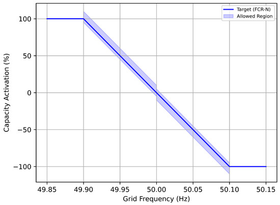
Figure 1.
FCR-N stationary requirement; blue graph and the shaded blue area depict, respectively, the mandatory target response and the allowed region for steady state activation of PFR.
A notable characteristic of the stationary requirement is the symmetrical target response about the nominal frequency. Mathematically, the mandatory target for active power P is defined by a sum of two terms
where is grid frequency deviation from the nominal value clamped between and ; and is the procured PFR capacity, which is a constant for each one-hour interval of PFC [3].
Steady state activation of PFR is assessed by a step and a linearity test. In the step test a synthetic grid frequency signal, consisting of steps from to , from to and from back to , is injected to a reserve system either directly to a frequency measuring device or in software. The active power measurements are recorded for validation. In the linearity test sequential 20 steps are injected so that linearity—in accordance with the stationary requirement depicted in Figure 1—is validated for the full range of feasible capacity activations.
The dynamic requirements for PFR are validated by a set of sine sweep tests. In each sine sweep test a synthetic sinusoidal grid frequency signal with a specified time period (10 , 15 , 25 , 40 , 50 , 60 , 70 , 90 , 150 and 300 ) and amplitude of is injected to the reserve system and the active power measurements are recorded for validation. The response of a linear time-invariant system (LTI) to a sinusoidal input is also sinusoidal. In accordance with the stationary requirement a FCR-N is approximately linear. Thus, sinusoidal least squares fit is performed in order to determine frequency response (gain and phase shift) for each input frequency. The frequency response data are represented by complex numbers. The set of input frequencies and frequency response data define an empirical frequency function
where is the input frequency in unit of radians per second.
Fingrid specifies analytic first order transfer function model of the power grid. Dynamic stability is assessed by application of Nyquist’s stability criterion to the open loop model constructed from and . Qualitatively, the Nyquist’s criterion states that a negative feedback LTI system is stable if the corresponding open loop system has sufficiently small gain at input frequencies for which the phase shift is close to 180° (otherwise the system would effectively suffer from destabilizing positive feedback at the specific input frequency). Dynamic performance is sufficient if the closed loop gain of the negative feedback model constructed from and is below a predefined upper bound. Dynamic linearity requirement is specified in terms of normalized root mean square error of the sinusoidal least squares fit [3].
The analytic first order transfer function model for dynamic stability assessment is defined by (for FCR-N)
where is the Laplace variable [3]. It is noteworthy that a pure delay of approximately results in failure of the requirement. Of course, a real reserve system does not introduce pure delay; however, the value provided here can still serve as a guide during implementation.
3.2. Case Study: HVAC Laboratory
Figure 2 shows a picture of the stand-alone AHU installed in the HVAC laboratory at the Myllypuro campus of Metropolia. Figure 3 is a simplified schematic of the AHU and other interconnected components. The unit consists of supply, return and recirculation air ducts with associated dampers. The supply and return ducts contain air filters and VFD controlled three-phase squirrel cage induction motors rated at which are attached to centrifugal fans. The supply duct also has heating and cooling coils.
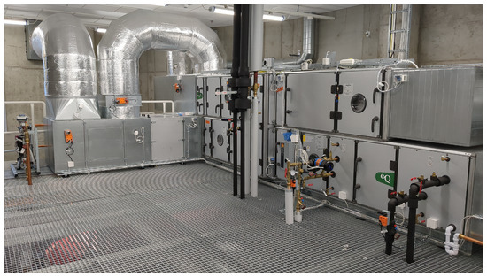
Figure 2.
The air handling unit located in the HVAC laboratory at Myllypuro campus of Metropolia.
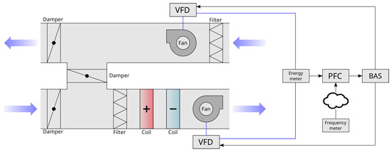
Figure 3.
Schematic of the air handling unit in the HVAC laboratory at Myllypuro. It is desirable to stream the frequency measurement over a network to improve economic viability of an aggregated reserve. PFC can be alternatively implemented in the BAS.
The VFDs (VLT HVAC Drive FC 102 by Danfoss [22]) implement two internal motor control modes: open loop control (V/f control) and closed loop control with configurable PID controller parameters and external reference (analog or digital over Modbus RTU). Both modes implement programmable motor ramp rate limiters. In this research the VFDs are configured to operate in the open loop control mode. Thus, PFC must be implemented by altering motor speed setpoint based on grid frequency measurement. This choice facilitates implementation since the setpoint can usually be controlled via a building automation system (BAS) instead of directly interfacing with the VFD—a factor favorable for economic viability.
Unfortunately, providing PFC by altering fan speed setpoint via a BAS, as opposed to directly interfacing with a VFD, comes with a compromise: delay is introduced by the BAS and any additional communication links. Delay in closed loop active power control can degrade performance and stability. Smaller controller gains are generally needed to alleviate the degradation; however, dynamic performance and stability of PFR, from the power grid point of view, can suffer as a consequence. Further, variations in the loop delay—for example due to BAS communication link congestion—could destabilize the control of an already pre-qualified reserve resource. Thus, a certain degree of robustness, at the expense of PFR dynamics, would be required from the closed loop control. Open loop active power control, which is implemented in this research, does not suffer from the challenges associated with closed loop active power control.
The right-hand side of Figure 3 shows components external to the AHU that are part of the reserve system. In this research, software generated synthetic frequency signals are injected into the reserve during pre-qualification tests and operational test runs are carried out against historical frequency data for reproducibility. Hence, real-time frequency measurement is not utilized for demonstrating the PFC. A three-phase energy meter (EM24 by Carlo Gavazzi [23]) is installed on premises to measure supply and exhaust fan instantaneous active power in isolation of other electric loads. The VFDs also measure active power but the accuracy and precision are slightly worse. However, the open loop control selected in this article is not critically affected by reduced measurement accuracy and precision since measurements are not fed back to the controller so VFD provided measurements could be utilized (for data logging as required by the TSOs) to improve economic viability. Lastly, the PFC block in Figure 3 implements the open loop control, data acquisition and logging. The implementation is executed on a Linux-based operating system running on Raspberry Pi Compute Module-based EN61131–2 compliant Internet of Things gateway (RevPi Connect by Kunbus [24]).
A simple quantitative way of assessing the impact of PFC on indoor climate is by consideration of specific fan power (SFP). In general, SFP quantifies the required power to circulate a given amount of air through a fan system, such as an AHU. Various definitions exist so it is important to explicitly state the definition assumed in this article. Namely, the SFP of the AHU is calculated by the formula
where N is the number of measurements, P is an active power measurement, and and are, respectively, measurements of supply and exhaust air flow rate. That is, the ratio of fan energy consumption to circulated air is calculated for both supply and exhaust fans, and SFP is then defined as the worse (greater value) of the two.
3.3. Open-Loop Control
The relation between fan speed and fan power is approximated by the affinity laws. Specifically, fan power is approximately proportional to the third power of fan speed. However, VFDs introduce losses, and thus a more accurate relation between fan speed and incoming power is obtained by a general cubic function. The method of least-squares provides a straightforward approach for estimating parameters of the cubic function; however, the standard non-recursive least-squares used in this study does not take into account variations in the HVAC system. For example, control of VAV dampers has an impact on the fan speed-power relation.
In the absence of significant variations in the system curve—which characterizes the degree of obstruction to air flow in a HVAC system—the speed-power mapping can be predetermined by incrementally increasing fan speed in steps and recording average power over a short time interval. Figure 4 shows a plot of the mapping constructed for the ventilation fans of the case study. The function is inverted in order to compute target speed as a function of target active power which in turn is a function of reserve baseline, maintained reserve capacity and real-time frequency measurement (see Equation (2)).

Figure 4.
Least-squares cubic speed-power mapping (blue line) for the combined supply and exhaust fans of the AHU at Myllypuro campus. Red markers indicate the average power during a short interval of constant fan speed.
VFDs frequently implement a configurable motor ramp rate limiter, which has the important function of reducing magnitude of motor acceleration caused by frequent setpoint changes, potentially improving occupant comfort (e.g., less noise) and increasing both the VFD and the motor lifetime. Decreasing the ramp rate, however, comes with a crucial compromise: significant phase shift is introduced which degrades PFR dynamic stability. Ramp rate limit can be decreased until the stability criterion is close to not being satisfied. In this study the ramp rate was set to by an iterative process.
4. Results
This section first shows the results of the pre-qualification tests. Then the outcome of several PFC test runs against exemplary intervals of historical grid frequency data are explored; calculated SFP for each interval of PFC is compared to a benchmark value. PFC baseline is held constant at 1600 in each test, and PFC capacity is varied (400 , 600 , 800 ). In validation of the dynamic requirements, sine tests with periods of 60 , 70 , 90 , 150 and 300 are not included since the proposed method trivially fulfills the requirements at low frequencies.
4.1. Pre-Qualification
Figure 5 shows results from validation of the stationary linearity (capacity of 600 ). Smoothed steady state PFR activation remains within the allowed region shown in Figure 1. Figure 6 shows an example of a sine sweep test (time period of 50 ).
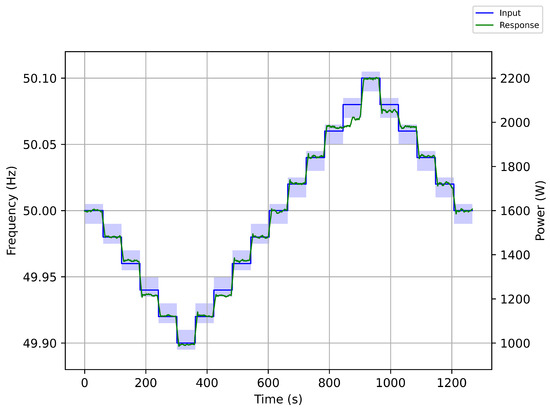
Figure 5.
FCR-N pre-qualification linearity test result. Blue graph shows the injected synthetic grid frequency (left-hand axis), and green graph shows combined instantaneous active power of the fans filtered as per Fingrid’s requirements (right-hand axis). The shaded blue area depicts the allowed region.
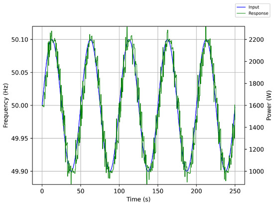
Figure 6.
FCR-N pre-qualification sine test result. Blue graph shows the injected synthetic grid frequency (left-hand axis), and green graph shows combined instantaneous active power of the fans (right-hand axis).
Figure 7 and Figure 8 show results from the sine sweep tests. Each marker corresponds to a specific sine sweep test (input frequency). However, it should be noted that the requirement must be satisfied for interpolated values as well. Dynamic performance criterion is satisfied by a large margin for all input frequencies; the performance is slightly worse at high input frequencies as expected due to the motor ramp rate limiter. The black circle in Figure 8 depicts the stability margin: the open loop (constructed from and , which are defined by Equations (2) and (3) frequency response must remain outside the circle for all input frequencies. Larger reserve capacity reduces gain but increases phase shift so that the criterion is not satisfied with a reserve capacity of 800 . Decreasing the motor ramp rate would be necessary for the particular value of reserve capacity. Table 1 shows extracted data from the sine sweep tests (capacity of 600 ). Notably, normalized root mean square error of the sinusoidal fits are less than one (dynamic linearity requirement) by a significant margin of 0.678 or more although nonlinear ramp rate limiting is adapted.
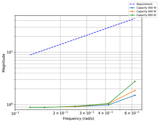
Figure 7.
Closed loop gain of the system constructed from and for varying reserve capacities.
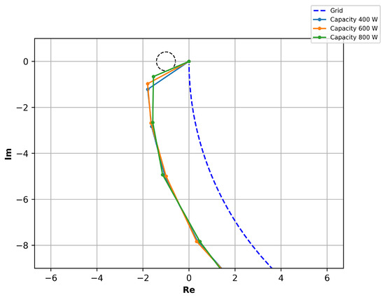
Figure 8.
Nyquist’s plot for the open loop system constructed from and for varying reserve capacities.

Table 1.
Data extracted from sine sweep tests (reserve capacity is 600).
4.2. Historical Data
Figure 9 shows an exemplary interval of PFC against historical frequency data with reserve capacity set to 600 . Table 2 lists the calculated SFP values for various 15-min intervals of historical frequency data. The 15-min intervals are chosen such that mean frequency is within from nominal frequency and the variance is the highest of the year 2022. The criteria enable fair comparison because long term frequency is remarkably close to nominal value of 50 . Higher than normal variance is chosen so that the results are representative of the worst-case scenario. Calculated SFP for a constant power corresponding to reserve baseline (1600 ) is 2.04856 kPa. The results indicate that ventilation efficiency; and consequently, indoor climate is not markedly impacted by PFC.
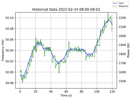
Figure 9.
Exemplary interval of PFC against historical frequency data (24 February 2022).
Table 2.
PFC test runs against historical grid frequency data collected and processed by Fingrid.
5. Discussion
The green energy transition threatens performance and stability of the power grid due to associated reduction in grid synchronous inertia. Generators and loads can compensate for the reduced inertia by providing PFR. However, recent trends in power systems challenge the response capacity of generators, and hence demand-side PFR is becoming increasingly attractive. Ventilation fans in particular present a promising class of demand-side loads capable of PFR, because of their ubiquity in modern HVAC installations, relatively large power consumption, excellent controllability by modern VFDs and inherent flexibility attributable to relatively slow thermal and ventilation dynamics of indoor spaces.
Unfortunately, PFR provision by ventilation fans of an AHU poses several challenges: PFR must have dynamically acceptable impact on the power grid, must have tolerable impact on indoor climate and should be economically viable to implement. This research focused on the Nordic synchronous area where stringent new technical requirements—including frequency domain dynamic requirements—have been recently established. The PFC method proposed in this article for a stand-alone unit consisting in an AHU is shown to pre-qualify according to the technical requirements. Further, it is shown that the proposed PFC design has tolerable impact on ventilation efficiency, and consequently, indoor climate. Finally, the open loop control could be implemented by interfacing with a BAS rather than directly with an AHU (VFDs) which positively affects economic viability.
Indoor climate could be assessed in a multitude of methods; for example, PFC could be performed while an occupied zone is measured for CO2 concentration. However; CO2 is only one of many compounds that can cause occupant discomfort [25] so a more thorough study would involve human subjects who provide information about perceived impact of PFC on air quality, noise levels etc. Unfortunately, obtaining trustworthy results from such a study would require a large cohort, and would not necessarily generalize to different HVAC installations. Hence, this article conducted an analysis based on SFP for assessment of the impact of PFC on indoor climate.
In contrast to previous research, this article provided several novel contributions. Rominger et al. do not investigate dynamic performance or stability of the control [8]. PID control (for active power) can effectively eliminate steady state error in the response; however, performant and stable PID control requires low delay in the feedback loop—a requirement which may incur additional implementation costs. The authors include a brief assessment of the impact of PFC on air supply based on a distribution of historical grid frequency data. However, given the presently relatively low valuation of PFR capacity it is worthwhile to assess ventilation efficiency based on measurements of active power and air flow in order to account for any inefficiencies caused by frequent changes in fan speed.
The approach taken by Hao et al. has the benefit of improving setpoint temperature tracking [15]; however, it is questionable whether such approach could be adapted for PFC fulfilling the new Nordic technical requirements without significantly reducing the temperature tracking performance (by adjustment of linear-quadratic regulator weights). Both Hao et al. and MacDonald et al. consider linearized model for fan power. A linear model is not suitable for the case study investigated in this research as indicated by the pre-qualification requirements presented in Section 3.
The primary limitations of this study should be reiterated. The open loop control described in this research requires a mapping from fan speed to fan power. Such mapping was deduced by the least-squares method prior to PFR provision. Therefore, variations, such as those caused by VAV dampers, in the HVAC system cannot be accounted for during PFC. Furthermore, impact on indoor climate was analyzed based on an investigation of the impact of PFR on ventilation efficiency. The assessment utilized historical grid frequency data with high variance and near-nominal average value. This choice guarantees good estimate of long-term impact on ventilation efficiency due to annual average frequency being very close to the nominal frequency; however, persistent frequency disturbances, which temporarily impact indoor climate, were not in the focus of this study. As stated in Section 3.1, aggregation is necessary for provision of PFR by AHUs so an aggregation strategy could aim to mitigate risks concerning lengthy under-frequency disturbances (resulting in lowered ventilation rate). However, such strategies were not in the focus of this research.
Future research could investigate PFC methods in VAV systems with interdependent variables and significantly varying HVAC system curves. Methods for estimating reserve baseline and controlling ventilation fans in such a way that PFC does not affect the baseline (since baseline ought to only account for active power not part of PFR) are crucial. In a broader context aggregation is also an important consideration: motor ramp rate limits could be significantly reduced to potentially improve occupant comfort and equipment lifetime if fast-reacting resources (e.g., a battery) were aggregated with ventilation fans. The open loop control method used in this study could be extended to an adaptive implementation by an online least-squares method such as the recursive least-squares (RLS). Finally, dynamic characteristics of PFC provided by closed loop active power control requires further research.
6. Conclusions
This research proposed a method for PFC by an AHU. The implementation was pre-qualified in accordance with the new Nordic requirements for PFC, which introduce stringent frequency domain dynamic requirements. Despite its excellent dynamic performance, the PFC was shown to have reasonable dynamic stability and tolerable impact on indoor climate. Further, the proposed open loop control simplifies implementation which is a crucial factor for economic viability.
This article has thus contributed to the green energy transition by showing that an AHU of a commercial HVAC system can participate in fast and dynamically favorable power grid balancing by providing PFR, which is becoming increasingly important form of frequency response in the modern low inertia power grid. Furthermore, overall energy efficiency is, in addition to enabling green forms of energy production, of paramount importance for the green energy transition. Thus, the acceptable impact of the proposed PFC design with an AHU on indoor air climate is a promising finding since a sizable portion of global energy consumption is attributed to HVAC systems and specifically AHUs.
Author Contributions
Conceptualization, N.K. and M.H.; methodology, N.K.; software, N.K.; validation, N.K.; formal analysis, N.K.; investigation, N.K.; resources, N.K. and M.H.; data curation, N.K.; writing—original draft preparation, N.K., M.H. and S.S.; writing—review and editing, N.K., M.H. and S.S.; visualization, N.K.; supervision, S.S. and V.V.; project administration, H.I. and J.K.; funding acquisition, H.I., J.K. and M.H. All authors have read and agreed to the published version of the manuscript.
Funding
This research was funded by the Promotion Center for Electrical Engineering and Energy Efficiency (STEK ry) grant KITSI.
Data Availability Statement
Data are contained within the article.
Acknowledgments
The authors thank Metropolia University of Applied Sciences for providing excellent support and a laboratory environment for the case study.
Conflicts of Interest
The authors declare no conflict of interest.
Abbreviations
The following abbreviations are used in this manuscript:
| AHU | Air handling unit |
| BAS | Building automation system |
| FCR | Frequency containment reserve |
| FCR-D | Frequency containment reserve for disturbances |
| FCR-N | Frequency containment reserve for normal operation |
| FFR | Fast frequency reserve |
| HVAC | Heating, ventilation and air conditioning |
| PFC | Primary frequency control |
| PFR | Primary frequency response |
| RLS | Recursive least squares |
| SFC | Secondary frequency control |
| SFP | Specific fan power |
| VAV | Variable air volume |
| VFD | Variable-frequency drive |
References
- Ahmad, M.W.; Mourshed, M.; Yuce, B.; Rezgui, Y. Computational intelligence techniques for HVAC systems: A review. Build. Simul. 2016, 9, 359–398. [Google Scholar] [CrossRef]
- Maddalena, R.L.; Mendell, M.J.; Eliseeva, K.; Eliseeva, K.; Chan, W.R.; Sullivan, D.P.; Russell, M.L.; Satish, U.; Fisk, W.J. Effects of ventilation rate per person and per floor area on perceived air quality, sick building syndrome symptoms, and decision-making. Indoor Air 2015, 25, 362–370. [Google Scholar] [CrossRef] [PubMed]
- Technical Requirements for Frequency Containment Reserve Provision in the Nordic Synchronous Area. Available online: https://www.fingrid.fi/globalassets/dokumentit/fi/sahkomarkkinat/reservit/technical-requirements-for-frequency-containment-reserve-provision-in-the-nordic-synchronous-area.pdf (accessed on 17 May 2024).
- Terms and Conditions for Providers of Frequency Containment Reserves (FCR). Available online: https://www.fingrid.fi/globalassets/dokumentit/en/electricity-market/reserves/terms-and-conditions-for-providers-of-frequency-containment-reserves-fcr-id-391152.pdf (accessed on 17 May 2024).
- Härkönen, K.; Hannola, L.; Lassila, J.; Luoranen, M. Assessing the electric demand-side management potential of Helsinki’s public service building stock in ancillary markets. Sustain. Cities Soc. 2022, 76, 103460. [Google Scholar] [CrossRef]
- Frequency—Historical Data. Available online: https://data.fingrid.fi/en/datasets/339 (accessed on 17 May 2024).
- Karhula, N.; Sierla, S.; Ihasalo, H.; Ketomäki, J.; Huotari, M.; Vyatkin, V. Primary frequency control with an air handling unit. In Proceedings of the Seminar at Automaatiopäivät—Automation Days 2023, Helsinki, Finland, 28–29 March 2023. [Google Scholar]
- Rominger, J.; Kern, F.; Schmeck, H. Provision of frequency containment reserve with an aggregate of air handling units. Comput. Sci.-Res. Dev. 2018, 33, 215–221. [Google Scholar] [CrossRef]
- Beil, I.; Hiskens, I.; Backhaus, S. Frequency Regulation From Commercial Building HVAC Demand Response. Proc. IEEE 2016, 104, 745–757. [Google Scholar] [CrossRef]
- Zhao, P.; Henze, G.; Plamp, S.; Cushing, V. Evaluation of commercial building HVAC systems as frequency regulation providers. Energy Build. 2013, 67, 225–235. [Google Scholar] [CrossRef]
- Maasoumy, M.; Ortiz, J.; Sangiovanni-Vincentelli, A. Flexibility of Commercial Building HVAC Fan as Ancillary Service for Smart Grid. In Proceedings of the Green Energy and Systems Conference, Long Beach, CA, USA, 25 November 2013. [Google Scholar]
- Adetola, V.; Lin, F.; Yuan, S.; Reeve, H. Building Flexibility Estimation and Control for Grid Ancillary Services. In Proceedings of the International High Performance Buildings Conference, Indianapolis, IN, USA, 9–12 July 2018. [Google Scholar]
- Lin, Y.; Barooah, P.; Meyn, S.; Middelkoop, T. Experimental Evaluation of Frequency Regulation From Commercial Building HVAC Systems. IEEE Trans. Smart Grid 2015, 6, 776–783. [Google Scholar] [CrossRef]
- Lin, Y.; Barooah, P.; Meyn, S.; Middelkoop, T. Demand side frequency regulation from commercial building HVAC systems: An experimental study. In Proceedings of the American Control Conference (ACC), Chicago, IL, USA, 1–3 July 2015. [Google Scholar]
- Hao, H.; Middelkoop, T.; Barooah, P.; Meyn, S. How demand response from commercial buildings will provide the regulation needs of the grid. In Proceedings of the Allerton Conference on Communication, Control, and Computing (Allerton), Monticello, IL, USA, 1–5 October 2012. [Google Scholar]
- MacDonald, J.; Kiliccote, S.; Boch, J.; Chen, J.; Nawy, R. Commercial Building Loads Providing Ancillary Services in PJM. In Proceedings of the ACEEE Summer Study on Energy Efficiency in Buildings, Pacific Grove, CA, USA, 17–22 August 2014. [Google Scholar]
- Härkönen, K.; Hannola, L.; Lassila, J.; Luoranen, M. Assessment of the Electric Demand Management Potential of Educational Buildings’ Mechanical Ventilation Systems. Energies 2023, 16, 85. [Google Scholar] [CrossRef]
- Keskar, A.; Anderson, D.; Johnson, J.; Hiskens, I.; Mathieu, J. Do commercial buildings become less efficient when they provide grid ancillary services? Energy Effic. 2020, 13, 487–501. [Google Scholar] [CrossRef]
- Lu, X.; Adetola, V.; O’Neill, Z. What are the impacts on the HVAC system when it provides frequency regulation? Energy Build. 2021, 243, 110995. [Google Scholar] [CrossRef]
- MacDonald, J.; Vrettos, E.; Callaway, D. A Critical Exploration of the Efficiency Impacts of Demand Response from HVAC in Commercial Buildings. Proc. IEEE 2020, 108, 1623–1639. [Google Scholar] [CrossRef]
- Mäkinen, T.; Leinonen, A.; Ovaskainen, M. Modelling and benefits of combined operation of hydropower unit and battery energy storage system on grid primary frequency control. In Proceedings of the IEEE International Conference on Environment and Electrical Engineering and IEEE International Conference on Industrial and Commercial Power Systems Europe (EEEIC/ICPS Europe), Madrid, Spain, 9–12 June 2020. [Google Scholar]
- Enhanced VLT HVAC Drive FC 102. Available online: https://www.danfoss.com/en-us/products/dds/low-voltage-drives/vlt-drives/vlt-hvac-drive-fc-102/ (accessed on 30 April 2023).
- EM24DINAV23XE1PFB—Carlo Gavazzi. Available online: https://gavazzi.se/produkter/em24dinav23xe1pfb/ (accessed on 30 April 2023).
- RevPi Connect Base Module—Industrial Raspberry Pi. Available online: https://revolutionpi.com/revpi-connect/ (accessed on 30 April 2023).
- Mannan, M.; Al-Ghamdi, S. Indoor Air Quality in Buildings: A Comprehensive Review on the Factors Influencing Air Pollution in Residential and Commercial Structure. Int. J. Environ. Res. Public Health 2021, 18, 3276. [Google Scholar] [CrossRef] [PubMed]
Disclaimer/Publisher’s Note: The statements, opinions and data contained in all publications are solely those of the individual author(s) and contributor(s) and not of MDPI and/or the editor(s). MDPI and/or the editor(s) disclaim responsibility for any injury to people or property resulting from any ideas, methods, instructions or products referred to in the content. |
© 2024 by the authors. Licensee MDPI, Basel, Switzerland. This article is an open access article distributed under the terms and conditions of the Creative Commons Attribution (CC BY) license (https://creativecommons.org/licenses/by/4.0/).