1. Introduction
Energy consumption in the global building sector has dramatically increased due to population growth and rapid urbanization. The global growth rate of electricity in buildings is about 2.5% per year, while the current global electricity use in the building sector is around 30% of the total final energy consumption and over 55% of the global electricity demand [
1]. Accordingly, a significant rise in sustainable buildings has been noticed. Solar photovoltaics (PV) are among the most widely used renewable energy sources in buildings due to their zero operating noise and very low and ease-in maintenance [
2,
3]. However, PV systems heavily rely on energy storage systems (ESSs) to overcome their irregular power production nature. The most commonly adopted ESSs are electro-chemical batteries, due to their impact on the overall building energy management system (EMS) performance [
4].
The need for energy flexibility in sustainable buildings is highly needed to reach an optimal power share between different distributed energy systems (DERs) in different operation conditions [
5]. PV systems typically generate power according to the Maximum Power Point Tracking (MPPT) algorithm, which is usually implemented on all commercial PV inverters. Except for the curtailment function, PV inverters are commonly not controllable, and their operation point depends solely on weather conditions. In contrast to PV, ESSs can add high flexibility to the building local network. This may serve to provide a load peak shaving function [
6] or primary frequency regulation function [
7] or both [
8]. ESSs can be integrated into the DC bus along with the PV system; in this case, the exchanged ESS power depends solely on the DC voltage regulation. However, AC-linked architecture has recently been preferred by many manufacturers due to some advantages, such as the ability to control the ESS independently from the PV system and to participate in grid frequency regulation [
9]. In a residential building, the power demand side is mainly linked to the AC side of the energy hybrid system, with which the grid utility is also associated. A typical scenario is that the algebraic difference between PV generation and power demand is to be covered by a power combination of the ESS and the grid utility. In island mode, the ESS works as an energy buffer, trying to recover the PV surplus power, or as a secondary power source in higher peak demands; in this case, ESS is no longer controllable and can only be disconnected as a protection action in case of overcharging or over-discharging scenarios.
When it comes to EMS implementation, BEMS low-level controllers, such as programmable logic controllers (PLC), can host basic algorithms based on IF-THEN statements. Those algorithms operate the energy system based on predefined conditions. Such methods may not be able to drive the hybrid energy system optimally, as the control setpoints are selected manually. Recently, novel BEMS architectures have been aiming to push building owners or facility managers away from manually determining the different operational setpoints and give this mission to a higher supervisory layer, either using edge computing [
10] or cloud computing technologies [
11].
Fuzzy logic (FL) is a computing technique that can deal with information arising from computational perception and cognition, that is, information that is uncertain, imprecise, vague, partially true, or without sharp boundaries [
12]. In energy management, the power of FL is its ability to act as an online decision-making tool that covers an infinity of operation conditions, e.g., whether the battery should be charged or discharged at a certain condition and at what rate. In this regard, fuzzy set theory offers a good resolution as a mathematical approach designed to model the vagueness and imprecision of a human cognitive process. In the case of energy systems, various FL-based approaches have been proposed and validated [
13]. An intelligent multi-objective EMS for a microgrid is proposed and simulated in [
14], in which FL is responsible for battery operation scheduling. The proposed method accomplished 1.35% and 5.76% cost savings and 2.96% and 6.1% of lower emissions compared to the heuristic flowchart and the conventional opportunity charging approaches, respectively. A similar approach is suggested and validated in [
15] for the management of stand-alone wind turbines, which are PV/hydrogen/ESS hybrid systems. A total cost savings of 13% was achieved over a control state-based EMS in simulation. It has been noted in previous works that all FL-based EMS approaches take actions on the controllable energy generators/buffers in real time, either in stand-alone or grid-connected modes separately. Up to now, no FL approach has been designed to deal with both operation modes simultaneously. It has also been noticed that the most common way to validate FL approaches, as an EMS, was in the digital simulation stage only [
16,
17]. The authors of [
18] validated a similar method for the energy management of a PV/Diesel generator/ESS hybrid ship based on experimental data issued from a BEMS; however, no real implementation was carried out. Moreover, to date, integration into an existing BEMS has not yet been investigated or validated.
This article addresses and validates a systematic approach to implementing a fuzzy EMS into a BEMS using edge computing technology. Along with the ESS charging and discharging control, the proposed FL-based energy manager uses the connectivity to the main grid utility as an additional control action. Therefore, the implemented fuzzy rules are designed with regard to the system constraints associated with both operation modes: grid-connected and island modes. The proposed method is hosted on an edge device, which is a Windows Personal Computer (PC), with which the communication with the BEMS low-level controller was established using a serial communication protocol. The remainder of this paper is organized into three main sections:
Section 2 describes the proposed FL algorithm for PV/ESS management. In
Section 3, the experimental validation setup is clarified, while
Section 4 provides some results and discussions.
2. Materials and Methods
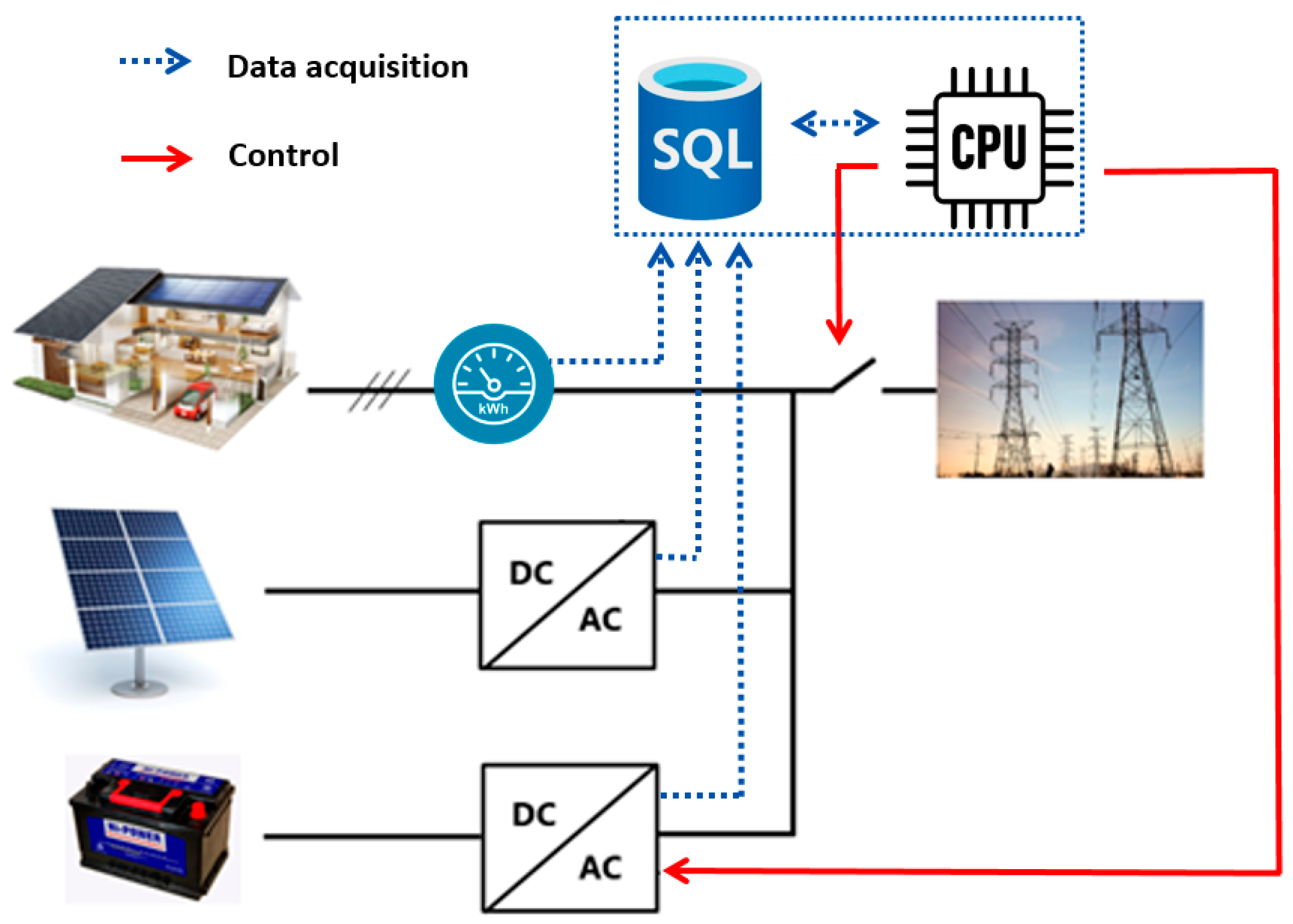
The proposed EMS is based on continuously performing control actions each cycle time after taking new measurement data. PV power supply data are collected, via Modbus protocol, from the PV inverter; batteries’ status data (SOC, voltage and current) and voltage/power data from DC and AC sides are collected with a similar protocol from the ESS inverter/charger, while power consumption data are collected from the energy meter. Collected data are stored in a local database after being processed by a PLC. Starting from this point, Sugeno fuzzy rules are responsible for finding out, in real time, the optimal values for the decision variables, which are the ESS current setpoint to be sent to the ESS inverter/charger and the connection/disconnection command to be sent to the main grid relay. A simplified diagram of the hybrid energy system, showing the role of the proposed EMS, is presented in
Figure 1 (PLC and many other data processing auxiliaries are not displayed here for simplification).
2.1. Power Balance Equation
The power flow equation is formulated as below:
where
PL is the electric load power;
is the supplied PV power;
and
are the batteries bank voltage and current, respectively;
is the exchanged grid power;
is the grid relay (
); and
and
are the efficiency of PV and the batteries bank system, respectively, including the power converters’ efficiencies.
2.2. Battery State of Charge Equation
ESS SOC is a key parameter that should be supervised continuously, and it is determined with the equation formulated below:
where
SOC(
t) is the actual battery SOC at time t in (%);
SOC(
t0) is the initial SOC at time
t0 in (%);
C is the battery nominal capacity in (Ah); and
IB is the battery charge/discharge current in (A), which is obtained using Equation (3).
where
PB is the algebraic value of the batteries’ power. To reduce the algorithm complexity,
is chosen as constant all the time (48 V).
2.3. Fuzzy Logic Control Structure
As mentioned previously, the suggested FL energy manager uses real-time status data from the building local network to optimally adjust the power flow. In this article, three data inputs are required to build up optimal EMS decision variables:
With this control framework, the power flow in the network, the energy storage constraints, and the energy cost hare considered by taking an infinity of possible operation scenarios, which is the fundamental advantage of using the fuzzy logic approach in this study.
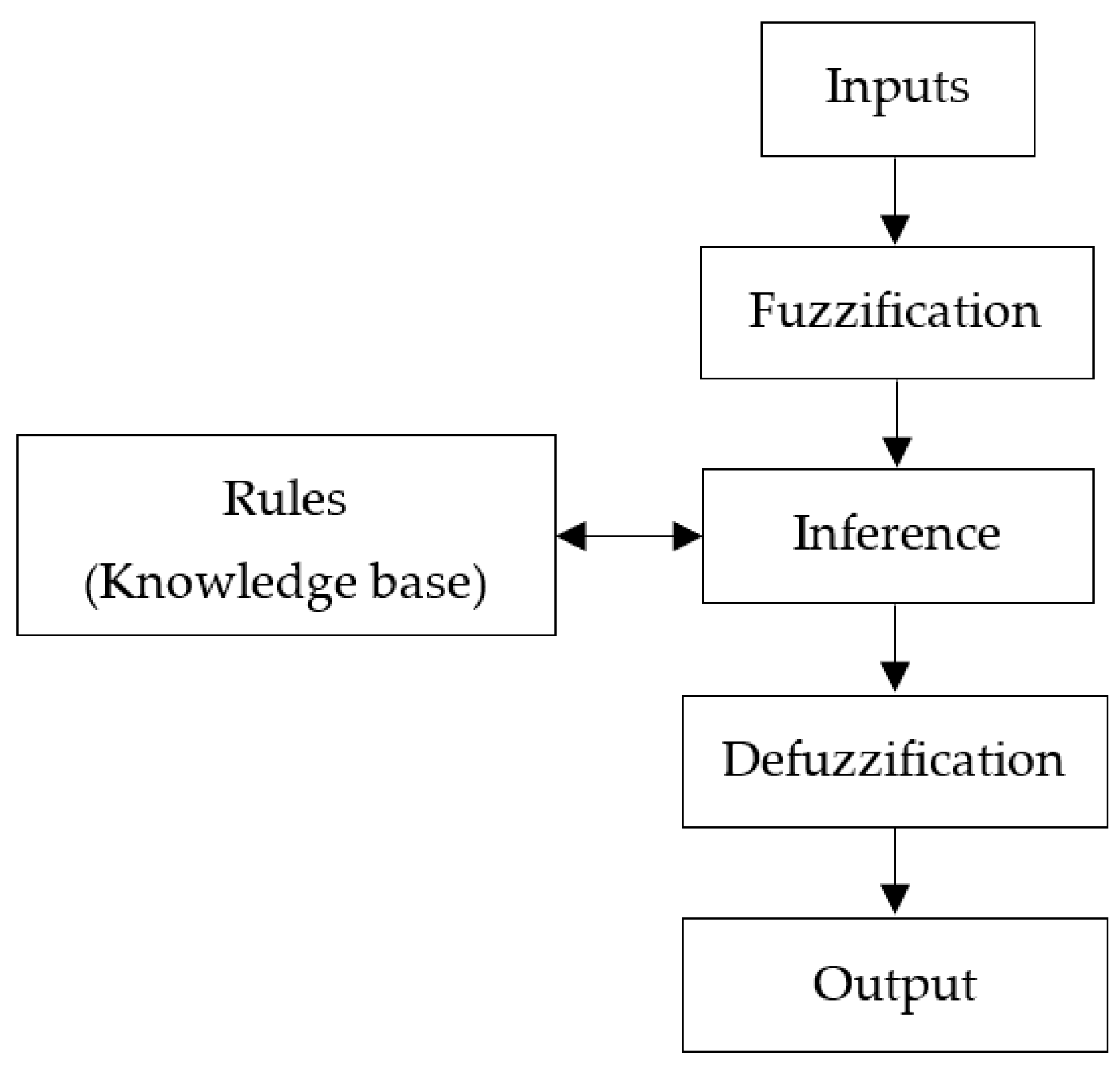
The structure of fuzzy logic signal processing stages is summarized in
Figure 2. The purpose of fuzzification is to encode to precision input values into fuzzy linguistic values. The measurement values are always crisp in general. Therefore, they have to be translated to proper terms of the corresponding linguistic variables, and this process is called fuzzification or coding input. Fuzzy inference is a method that interprets the values in the input variables and, based on some set of rules, assigns values to the output. In fuzzy logic, the truth of any statement becomes a matter of a degree between 0 and 1. Defuzzification is the process of obtaining a single number from the output of the aggregated fuzzy set. It is used to transfer fuzzy inference results into a crisp output. In other words, defuzzification is realized by a decision-making algorithm that selects the best crisp value based on a fuzzy set.
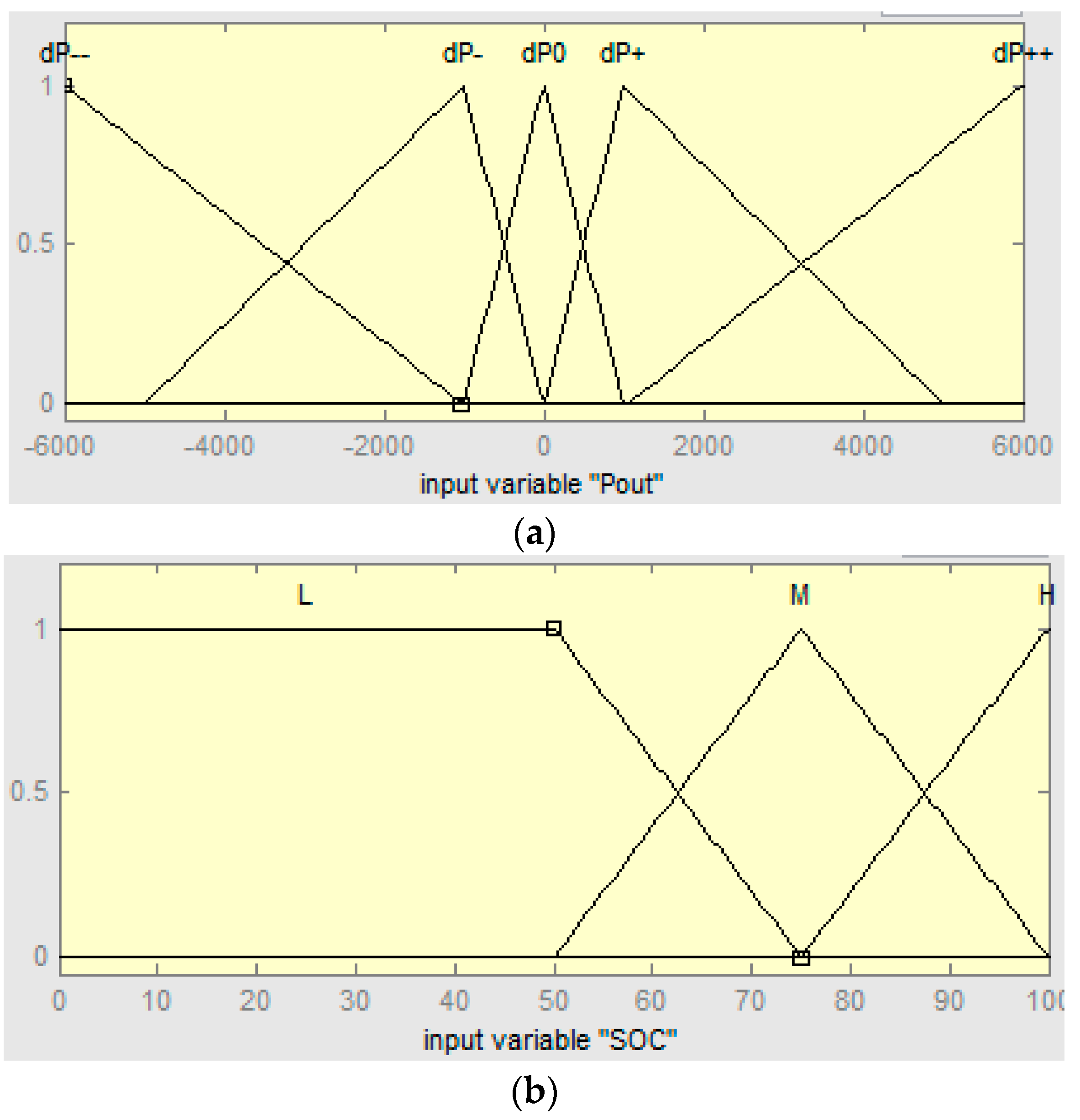
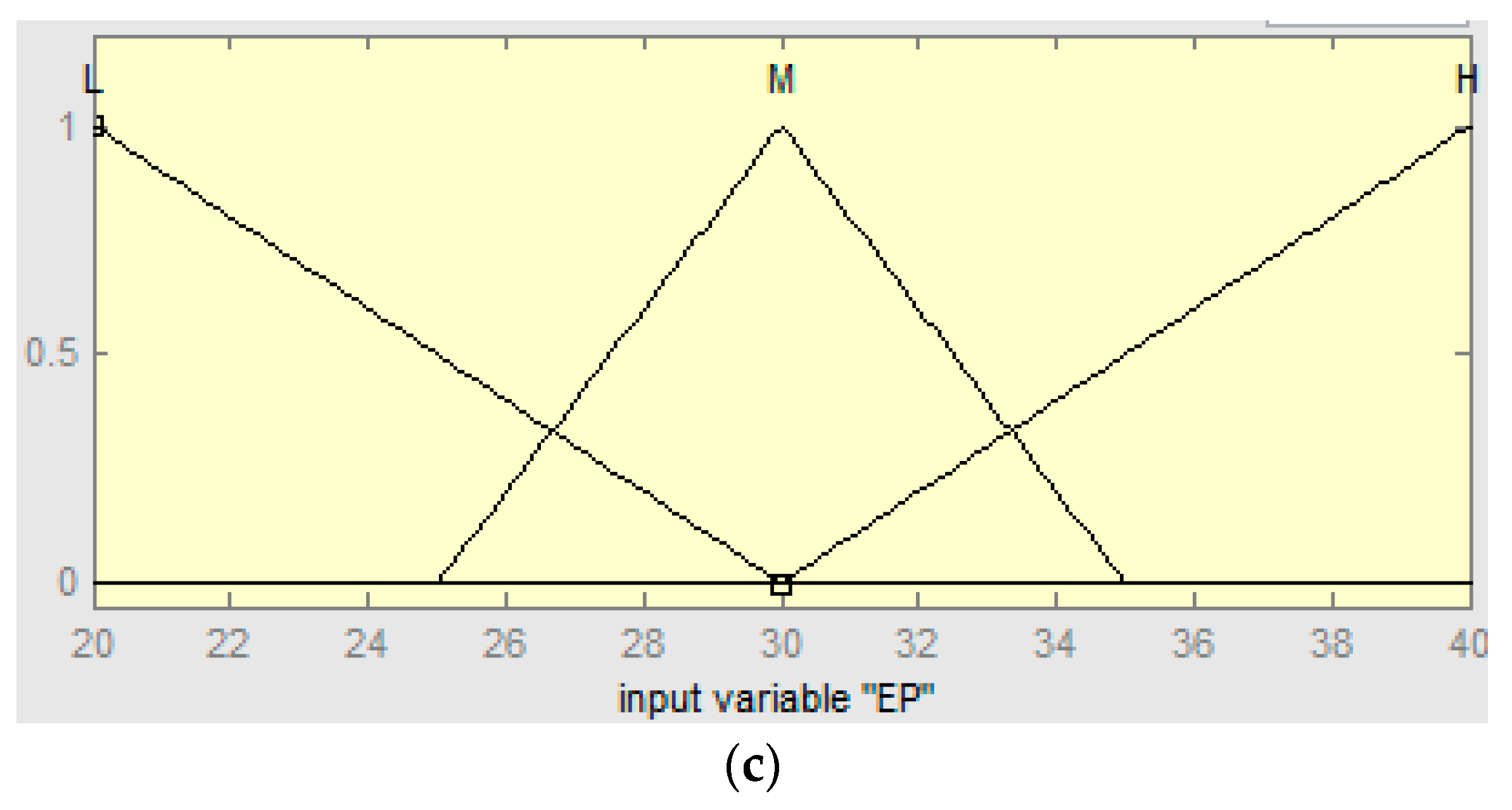
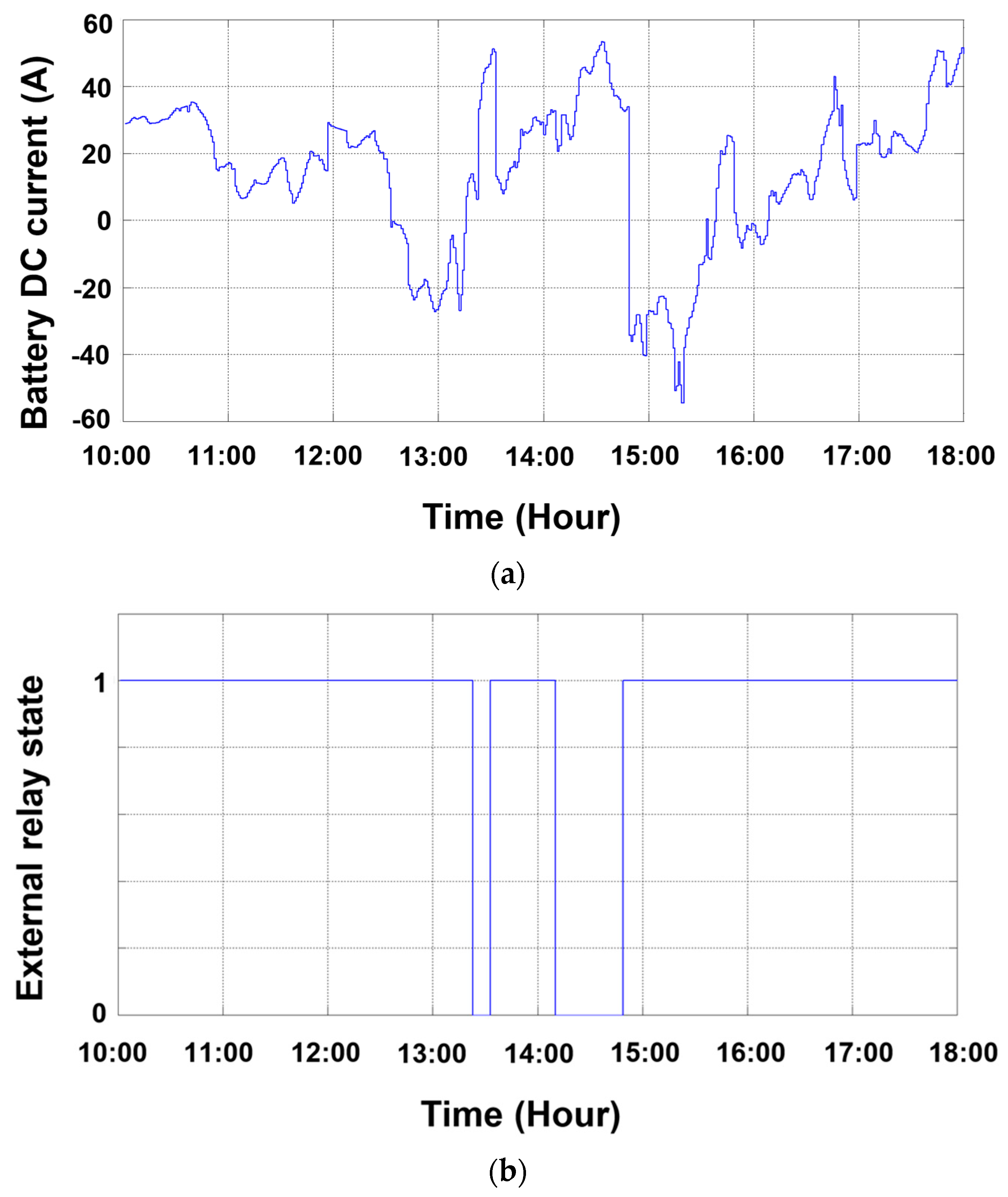
Different triangle and trapezoidal membership functions are chosen to interpret the input variables. Based on the fuzzy rules, the controller can adjust the power flow in the building’s local network using two parameters: the ESS current, which is controlled by the inverter/charging, and the external grid relay.
Figure 3 shows a simplified structure of the proposed fuzzy controller, while
Figure 4 displays the number and types of fuzzy membership functions of the input/output variables.
The fuzzy rules are designed for the following purposes:
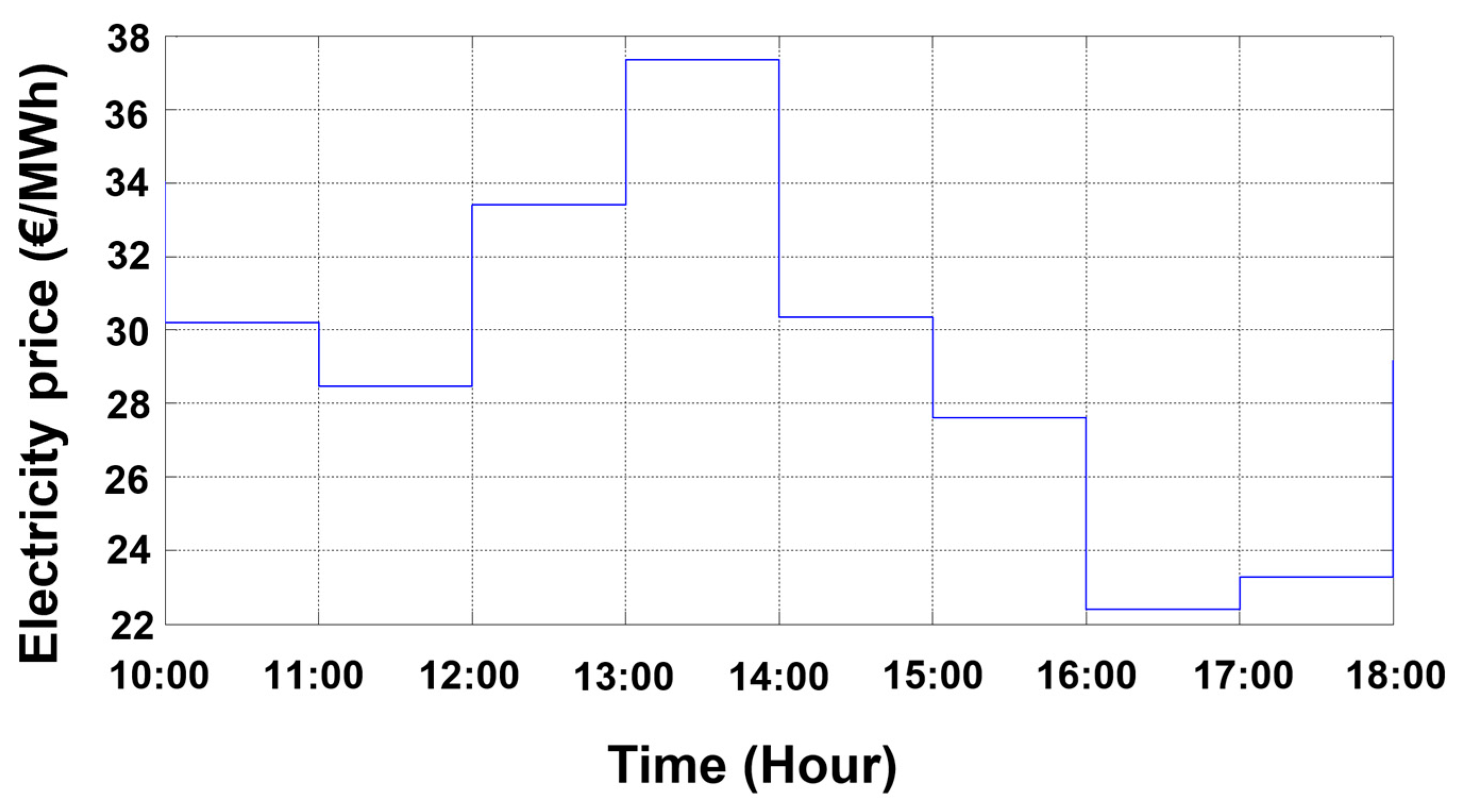
Decreasing the cost of energy imported from the grid utility taking into consideration the hourly electricity price.
Maximizing the PV power share.
Charging the batteries from the grid when the electricity price is low and from the excess PV power when it is high; the latter option is feasible by opening the external relay.
Inject more power to the public grid when the electricity price is high.
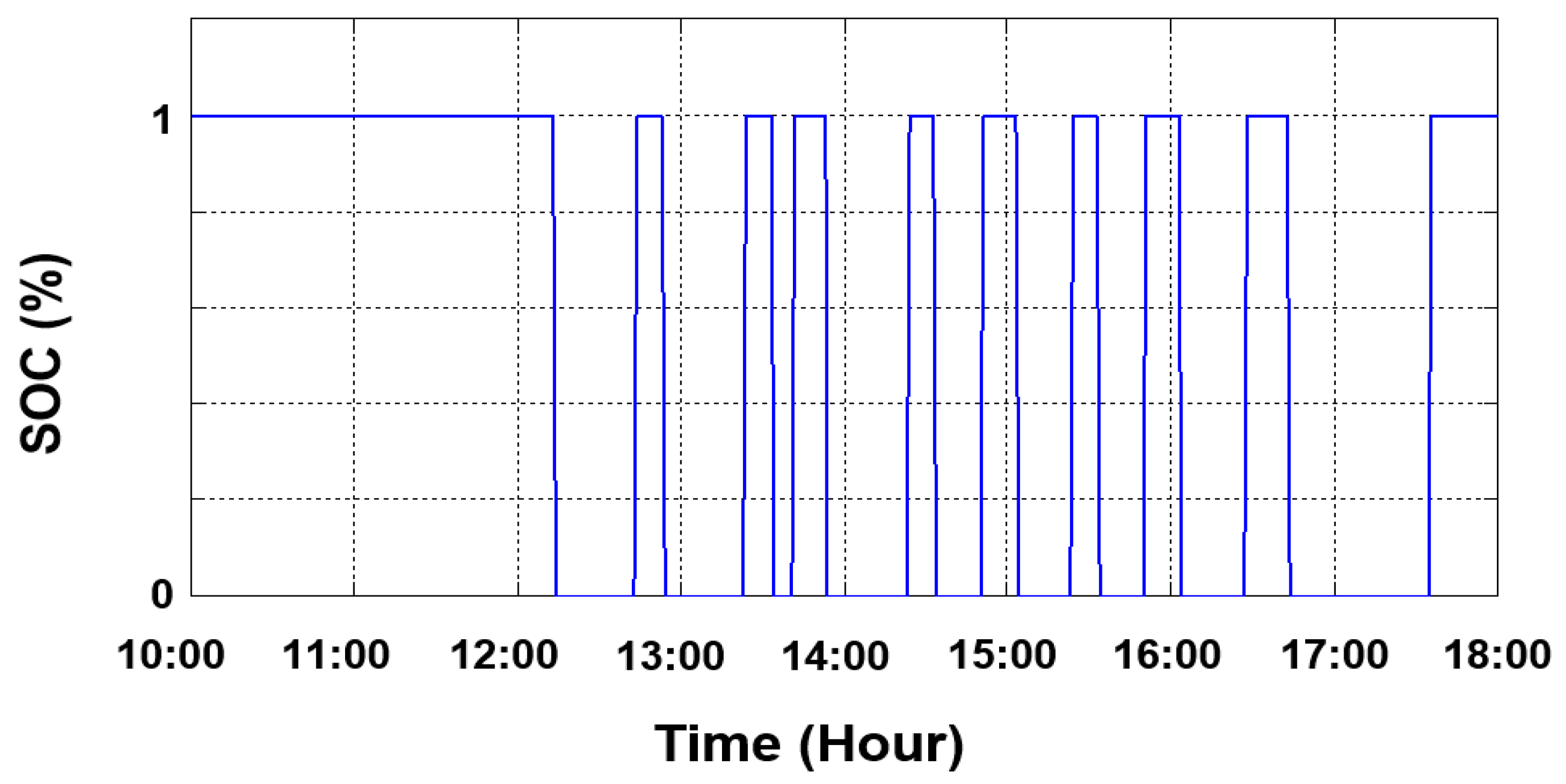
Keep SOC between the two upper and lower allowable limits.
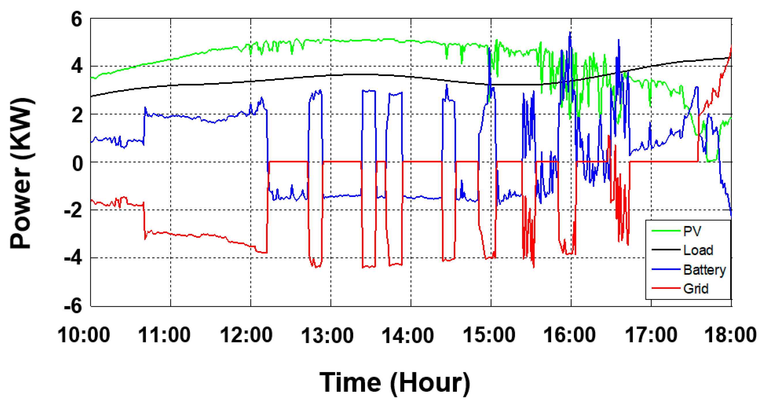
Maximize the use of PV power for load supply, especially when the power price is high.
Operate the microgrid independently of the electrical grid as much as the system constraints allow.
In this context, 45 rules are created to manage and monitor the power flow in the building hybrid system, including 18 rules for ESS charging mode, 18 rules for grid feeding mode, and 9 rules for island mode, as listed in
Appendix A (
Table A1). Maximizing self-consumption is targeted because the energy selling prices are always lower than the purchasing ones; therefore, it is valuable to benefit from the local renewable energies rather than selling them to the grid utility owner. For this purpose, the microgrid islanding mode is mainly targeted. Physically, this is possible thanks to an electric relay called “grid external relay,” which is already integrated in the ESS inverter/charger. This relay can connect the whole building’s local network to the grid utility as well as disconnect it.
Indeed, islanding the building microgrid can lead to serious damages to the building’s electric equipment in some situations, e.g., if a significant amount of extra PV power is locally supplied, this can lead to batteries overcharging in low power demand. Similarly, higher power demands cause an over-discharging scenario in the case of low PV supply. Luckily, power converter manufacturers for PV and battery systems are now taking these situations into consideration, i.e., the ESS inverter/charger is equipped with a frequency/voltage control mechanism that regulates the power fed to the local network according to the evolution of frequency and voltage at the connection point.
To show the FL energy manager response for different operation situations,
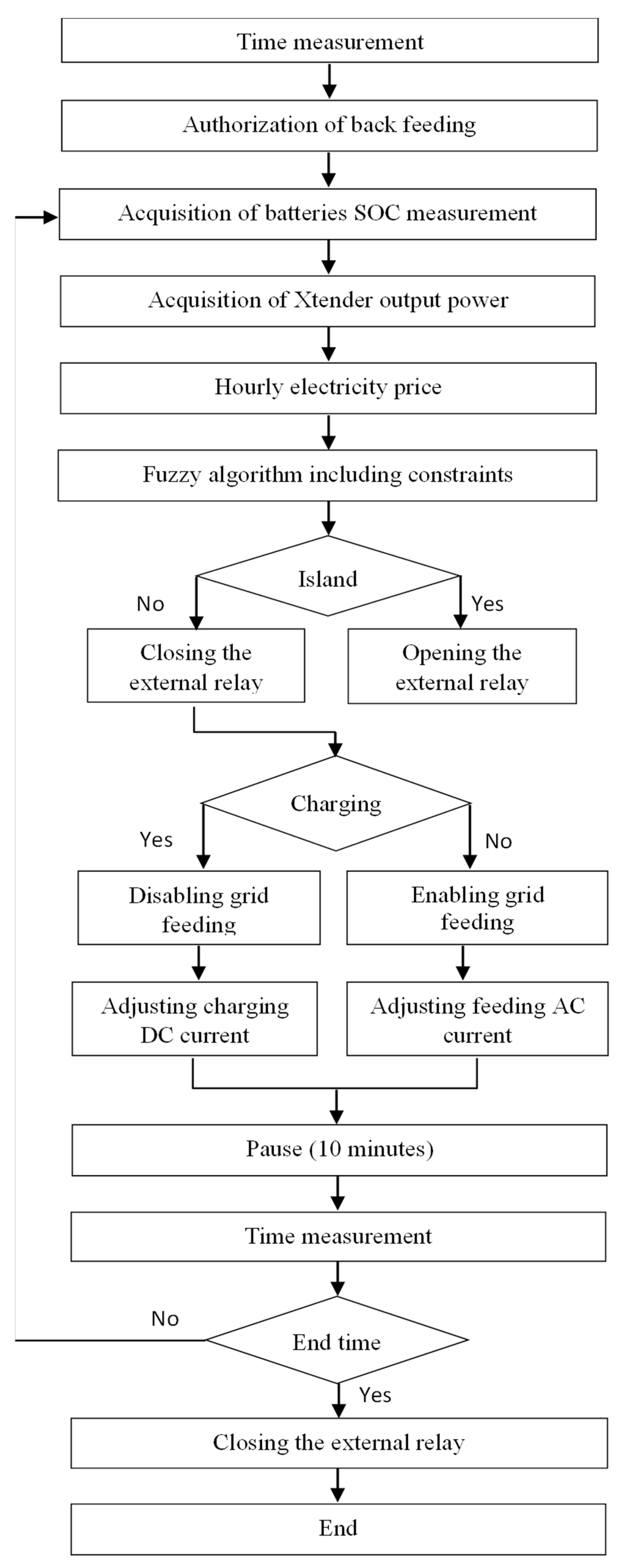
Figure 5 displays the fuzzy surfaces generated based on the created rules and the variables membership functions. It is worth mentioning that the proposed FL energy manager cannot deliver exact Boolean values for the output R, which corresponds to the external grid relay command. Therefore, a rounding function is added at the corresponding output to fix this issue. The different command actions, which should be sent from the edge controller to the ESS inverter/charger using the FL algorithm, are displayed within the flowchart
Figure A1 in
Appendix B.
2.4. Constraints
The ESS operation limits are highly crucial when designing the fuzzy rules; in this context, two important parameters are to be considered when performing the control: the maximum operational power of the inverter/charger and the upper/lower limits of
SOC, which are formulated in (4) and (5), respectively.
where
s the maximum allowed power supported by the ESS inverter/charger;
SOCmin and
SOCmax are the predefined minimum and maximum limits of ESS SOC, respectively; and ∆
T is the cycling control time.
Note that, in island mode, the fuzzy controller is no longer able to control ESS current; in this case, the ESS operational point depends solely on the power balance in the local microgrid between PV generation and power demands. However, in island mode, the ESS current should be kept supervised during the cycling control time ∆T to satisfy the constraints in (4) and (5).
2.5. Baseline Method (Rule-Based EMS)
Rule-based EMS is a simple method that offers a real-time evaluation of the energy system’s performance using pre-defined conditions (rules). In this study, a rule-based ESS management system based on real-time evaluation of SOC is developed. It defines the operation mode of the hybrid system according to the SOC level. The island mode is active only if the ESS constraints, formulated in (4) and (5), are satisfied. The flowchart of the proposed rule-based EMS is shown in
Figure 6.
Rule-based EMS is an efficient approach when it comes to cost-effective implementation. The rules are designed to focus mainly on ESS SOC variation. Operating ESS between predefined upper and lower limits offers various advantages. The lower limit protects ESS from deep undercharging scenarios, which increases the batteries’ life, and it also offers an energy backup in case any unexpected energy needs occur. The upper limit is to protect the batteries from overcharging issues, such as corrosion on the positive plates and excessive temperatures; the upper limit also ensures the energy recovery capacity of any sudden extra PV supply, particularly in island mode. The control commands used to ensure the targeted performance are the same as those used in the previous FL approach (external grid relay and ESS current). Rule-based methods can be performed online without requiring much computing time, which makes them suitable for real-time EMS.
3. Validation System Description
In this section, more details about the experimental setup and the implementation steps are given. The tests were carried out on the smart grid prototype of the Institute of Energy Systems Technologies (INES) at Offenburg University. This prototype makes it possible to demonstrate control and management policies using real industrial hardware, which makes the results replicable in any other application.
3.1. System Components
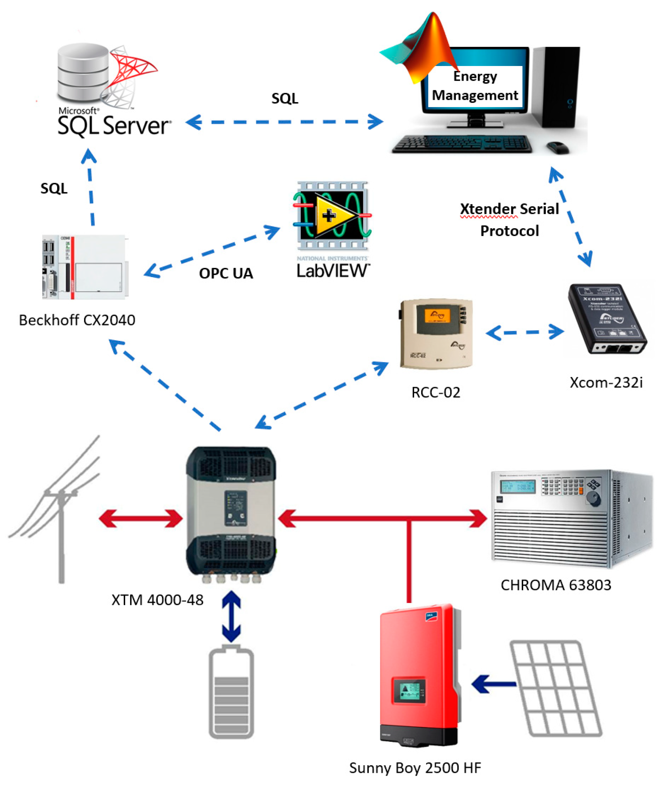
The experimental setup consists of three single-phase STUDER XTM 4000-48 Xtender inverter/charger devices in parallel to form a three-phase converter. This latter will control the exchange of power between 4.5 KW lead-acid batteries and the local building microgrid. The inverter/charger can also connect the whole hybrid system to the grid utility, or it can disconnect it to operate it as an island microgrid, as explained previously. The 6.3 KWp PV system is connected to the AC bus of the local network via three Sunny Boy 2500 HF inverters; these inverters are controlled to supply the maximum available power. The different system parameters are listed in
Table 1.
ESS SOC data feedback is essential for the EMS algorithm; data are measured permanently via a battery status processor (BSP) device that offers real-time measurements of all battery parameters (SOC, voltage, current, and temperature). PV and load powers are other required signals that are collected via transmitters and treated by means of BECKHOFF CX2040 PLC. To simulate a residential building’s power demand, three CHROMA 63,803 programmable loads are connected to the local network to form a three-phase load system. Those loads are controlled, remotely, to follow a real residential building power demand profile. All data are stored in real time in a local database. PLC communicates also with Labview software, version 14.0.0, which serves as a Human–Machine Interface (HMI) system, via Open Platform Communications United Architecture (OPC UA) to provide real-time data visualization and a user–system interaction tool.
The system was initially designed so the ESS current setpoint is to be generated continuously by PLC using a classical IF-THEN EMS algorithm (rule-based). Since our target is to apply a FL-based EMS, as explained earlier, a Windows PC, serving as an edge device, is responsible on generating the ESS current setpoint using a MATLAB code as a high-level programming language. At each cycle time, the system status data are queried from the database using MATLAB and Structured Query Language (SQL). Here, the FL algorithm can take over and map the system input data to the optimal outputs. In this case, PLC is bypassed when performing the control, and the edge device directly controls the ESS inverter/charger using a specific communication protocol called “Xtender Serial Protocol”. For this purpose, Xcom-232i is needed as a communication module. The corresponding control parameter to be written (ESS current) is defined in the Remote Control Center RCC-02, which has a direct control action on the inverter/charger. The complete experimental system is represented in
Figure 7. This process is being repeated continuously each control cycle time until the algorithm-stopping criteria are reached. Regarding the system dynamics, the chosen cycling time for the experiments is fixed at 10 min.
3.2. PC—Xtender Communication Protocol
The Xtender Serial Protocol is the communication path between Xcom-232i and the edge device (PC), which acts as a master, and the ESS power converter, which acts as a slave device. This protocol is highly similar to the industrial Modbus RTU; it consists of exchanging data frames composed of a header of 14 bytes, followed by a variable number of data bytes and 2 bytes of checksum. To facilitate the implementation of the protocol, a command line tool is used to communicate directly with the RCC-02, via Xcom-232i. As an example, to force the batteries to be charged with 12 A, the following command line statement can be built using the Windows command prompt:
Where write_property is the “Write” function; dst_addr = 101 is the device destination address, in this case, 101 for Xtender inverter/charger; object_id = 1138 is the “charging current” parameter ID; and value = 12.0 is the charging current value in Ampere.
To not overstate the content of this article, more information on the structure of the command lines, and on Xtender Serial Protocol in general, can be found in the documentation section of the manufacturer’s website. Combining the command line tool with a high-level programming language, like MATLAB, facilitates the conception of advanced EMS algorithms by simply calling predefined functions, such as “evalfis” for the Sugeno fuzzy inference system.
One advantage of the fuzzy EMS is that it can be considered as an online control procedure, i.e., the system status data evaluation and control actions are performed in real time. Therefore, no significant calculation time is needed. This makes it a very suitable approach when the computational efficacy is targeted. However, the time delay related to the data acquisition through industrial communication protocols, like the one explained earlier, may not be negligible!
5. Conclusions
This article addresses and validates an advanced edge-driven EMS approach. The technical feasibility of the implementation into an existing BEMS is mainly highlighted. For this, the fuzzy EMS algorithm was validated on two different climatic conditions. Thanks to the fuzzy data processing structure, an infinity of operation situations were considered during the control process. The efficacy of islanding the building microgrid as a control command was also demonstrated. The main features of the edge-driven fuzzy energy manager are as follows:
An infinity of operation conditions can be considered during the evaluation of the system status data before performing control.
Smooth control of ESS SOC.
The ability to add various data inputs with less complexity compared to rule-based EMS approaches.
Thanks to the edge communication interface, EMS commands can be sent via a low-level controller (PLC), which needs some additional software configurations, or directly to power converters without the need for any BEMS modifications. This last option is recommended only during the commissioning or test phase.
Thanks to the high hardware resources of the edge device, a high-level programming language, combined with industrial communication protocols, makes it possible to implement advanced EMS algorithms in BEMS.
In future work, the edge-driven EMS is to be cascaded on top of an eventual Supervisory Control and Data Acquisition (SCADA) system. Within this architecture, edge-driven EMS will act as a management system that monitors an entire energy network including different DERs. The communication in this situation should be performed through the low-level control for more consistency and to take advantage of the security policies that have already been implemented.
