Abstract
In this paper, an inductive power transfer (IPT) system without compensation elements is presented for small house appliances. The proposed system’s transmitter side is an independent induction heating cooktop. IPT can be achieved when the kettle with the receiving coils is placed on the transmitter coil. The coils are designed with a high coupling coefficient. The magnetic system model consisting of aligned transmitter and receiver coils is created in the Maxwell program. In the created model, the analysis depends on the air gap and frequency, which are the variables that affect the wireless power transfer. The electronic circuit simulation uses the coil model to examine the system’s dynamic behavior. The design of the transmitter/receiver coils of the IPT system is made with a cylindrical coil with a diameter of 145 mm, taking into account that it is compatible with the dimensions of the existing kettle and induction heating cooktops coil. A half-bridge series resonant converter circuit is used to adjust the power transferred to the load. To verify the simulation results and test the designed system, an experimental circuit using a 2200 W kettle is carried out. In the experiments, the air gap between the coils is kept constant at 7 mm, and measurements are taken for different powers. Experimental results confirm the magnetic model and simulation results. As a result, wireless power transfer is realized in a wide range without loss of performance in the kettle. System efficiency is greater than the 90% specified in the Ki cordless kitchen standard, and the harmonic currents drawn from the mains are lower than the values determined by the IEC 61000-3-2 standard.
1. Introduction
Today, wireless power transfer (WPT) technology is used in many applications, from low-power charged toothbrushes to high-powered electric vehicles, such as home electronics, biomedical devices, and portable smart devices [1,2,3,4,5]. The essential benefit that WPT systems provide to the user is that they can save the products from cable clutter and use them in a mobile way. They are dependable since they do not have electrical contact, making them a good solution for environments at risk from water and dust [6,7,8]. On the other hand, they have high cost, low efficiency, and high heating compared to cable systems.
WPT is carried out with three different methods such as radio frequency (RF), magnetic resonance (MR), and inductive coupling (IC) [9,10,11]. Inductive power transfer (IPT), one of the IC technologies, stands out as the least harmful method to health among the WPT methods. In this method, magnetic field coupling is used to transfer electrical power between the transmitter and receiver coils. The transfer distance (airgap) or coil misalignment has a significant impact on the transferred power. As the air gap between the coupling coils increases, the leakage inductance increases and the mutual inductance decreases [12]. Therefore, high-value current must be passed through the transmitter circuit to transfer a certain amount of power. Due to this high-value current, the losses in the system increase and the efficiency of the system decreases [13]. Therefore, the coils must be aligned vertically and horizontally and must also have the highest quality factor possible. When compared to RF technology, the transmission distance is shorter since a wave’s magnetic field weakens faster than its electric field [14]. Although the transmission distance is short, the transmitted power is up to 10 kW.
Studies are conducted in a variety of domains, such as magnetic stage, electronic circuit topology, control technique, and load sensing, because IPT is a large topic that depends on many distinct aspects [15]. The magnetic field lines between the transmitter and receiver coils in the IPT system must be steered with the minimum leakage possible. Therefore, aluminum plates are used in coil design with a size equivalent to the coil diameter. To achieve proper field orientation, the ferrite rods positioned between the coil windings and the aluminum plate must be carefully optimized. Ref. [16] has ensured that the power transferred to the receiver was realized at the desired efficiency.
The most critical parameter in the compatibility of the topologies used in IPT technology with the system is the energy requirement that is constantly stored and transferred. Other parameters used in topology selection are switching frequency, output power, and power density [17,18,19,20,21]. Generally, half-bridge (HB) and full-bridge (FB) topologies are preferred depending on the power transferred in the circuit. The semiconductor device selection is made depending on the switching frequency. Table 1 shows the application areas where WPT technology is used and the topology and semiconductor switch types used, depending on the switching frequency (fSW) and output power (POUT) [22].

Table 1.
Application areas, topologies and semiconductor power devices.
Resonant compensation must be utilized to get over the inherently poor coupling and the associated high leakage inductance to transmit power effectively and efficiently. In IPT systems, fundamental compensation networks, such as series–series (SS), series–parallel (SP), parallel–series (PS), and parallel–parallel (PP), have been applied extensively. Capacitors are employed on both sides of an SS compensation topology to reduce leakage inductance and increase power transfer efficiency in the presence of a relatively high air gap and leakage inductance [13].
The main application areas of IPT technology in consumer electronics are wireless small household appliances (SHA) and wireless personal care products [23,24]. Some of these applications have designs that include batteries. Especially in wireless SHAs, some disadvantages occur because of battery usage, such as weight, safety, and durability. In addition, the power of the devices in the wireless SHA varies widely. Battery usage in high-power products is impossible because of the increase in size and weight. For this reason, to provide WPT in all applications, a system design with a transmitter and receivers compatible with this transmitter should be made [25].
The Wireless Power Consortium (WPC) was founded in 2008 to develop a global standard for inductive charging technology. WPC develops many standards related to this technology. The Ki cordless kitchen standard is derived from the Qi standard used for wireless charging mobile devices. This standard is essential in producing safer, smarter, and more helpful kitchen appliances [26]. It ensures that products from different manufacturers can work together safely. It identifies transmitters and versatile cookers (rice cookers, toasters, blenders, coffee makers, air fryers, etc.) that wirelessly transmit up to 2200 W of power to smart wireless kitchen appliances and make them work without the clutter of wires. These small appliances are operated by placing them on adapted induction heating (IH) cooktops or transmitters located on a nonmetallic counter surface, stove, or under the kitchen countertops [27].
IPT and IH applications work according to the principle of applying the high-frequency alternating current obtained with the help of the converter to the planar coil. This similarity enables the development of applications covering IPT and IH features and the emergence of new products [28]. Today, induction cookers are placed under the kitchen table to expand the kitchen working area, obtain free work surfaces, and ensure easy cleaning. The IH cooktops used in this new generation of kitchens are built on the combined use of IH and WPT technologies. In these systems, the design of the magnetic system that is compatible with IH and provides WPT is important [29].
The kitchen applications of WPT in the literature are summarized in Table 2. In these studies, an IH cooktop or a separate transmitter system was used as the transmitter stage.
Table 2.
Literature survey on WPT small home appliances.
In [19], a fixed-output power WPT system with an SS compensation circuit used under kitchen countertops is proposed for kitchen appliances. Constant power transfer was obtained with a control method that depends only on the primary parameters. SS compensation is compact, but a power of 500 W transferred to the output is low for cooking. The efficiency of the system in which the FB topology is used varies between 79.0% and 95.0%.
The system’s performance was investigated using different compensation topologies techniques on the transmitter floor placed under the kitchen countertops [23]. A new PP compensation circuit is proposed to reduce electromagnetic interference (EMI). Theoretically, although the design was made for a working power of 2400 W, results were obtained from a 60 W application circuit.
In the study conducted in [30], the efficiency of the WPT system was increased by using an LCCL impedance matching circuit in Class E topology. In the system where LED light, stove, and fruit blender are used as load, 72 W of power is transferred to the output with 81.76% efficiency.
A wireless IH rice cooker with S-CCC compensation topology is presented in [31]. To obtain a constant output power, the HB topology with an additional PFC stage at the input is used. The transmitter side can work as a standalone induction cooker. The extra coil and compensation capacities between the transmitter and receiver coils provide power regulation. The system is difficult to implement, complex to control, costly, and heavy.
In [32], an additional receiver coil transfers 2200 W of power to the pan with the IH cooktop placed under the countertops. This way, the distance between the hob and the pan can increase. Series compensation capacitors use identical coils on the transmit and receive sides. Power and power factor values were examined based on distance, frequency, and quality factor. In the case of using an additional coil on the transmitter coil of the IH cooktop, the system performance increased compared to the case of not using the coil.
A new control method in the WPT system is presented to control the output power in [33]. A 200 W water heater is used as a load in the system where an SP compensation circuit is used in coils energized with FB topology. Thanks to the control method, constant power is transferred to the output even in case of a misalignment of the coils.
A typical kitchen appliance may use nearly 2.4 kW of power while operating normally [23]. However, as seen in Table 2, the studies except [31,32] were carried out at low power. Compensation elements are used in all studies to eliminate the negative effects of leakage inductances. As a result, the cost and volume of the systems have increased, and the controls have become more complex. They are also designed for constant operating power or a narrow power range.
This article proposes an IPT system to solve the above-mentioned research gaps. Thanks to the tightly coupled coils designed, power can be transferred to the load in a wide range and efficiently without compensation elements. There is no need for an additional transmitter stage as the proposed system can work in harmony with countertop induction cookers used in homes, as shown in Figure 1. Therefore, space and cost savings are achieved.
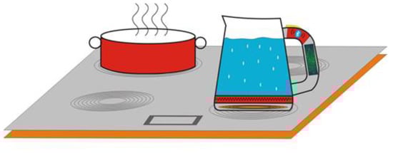
Figure 1.
IH cooktop and WPT kettle.
The main contributions of the proposed system are listed below.
- Power transfer is provided without using a compensation component. (In this way, the size of the small household appliance does not increase, and the cost is low as the desired operation is achieved with the least number of elements.)
- The system is capable of using the existing IH cooktop as a transmitter stage. (Eliminates the need for an additional transmitter stage.)
- A wide range of power is provided to the load, from 10% to 100% of its rated power. (Power transfer can be provided to high-power SHAs such as kettles, hot pots, rice cookers, toasters, etc.)
The paper is organized as follows. The basic structure and the efficiency expression of the wireless power transmission system and the basic working principle of the power converter used in the transmitter stage are given in Section 2. The “design criteria” of the proposed system are described in Section 3. First, the magnetic system is designed according to the criteria. The parameter changes of the coil are examined for different operating conditions. Second, the power converter components are determined. The control algorithm and fundamental principles are outlined in Section 4. The dynamic simulation model created to examine the operation of the proposed system and the results obtained from the model are given in Section 5. Experimental validation of the proposed system is presented in Section 6. Finally, the conclusions are offered in Section 7.
2. Principles of IPT
The system basically consists of three parts: the magnetic stage where the transmitter (primary) and receiver (secondary) coils are located, the load, and a power source. The general block diagram of the IPT system is given in Figure 2.
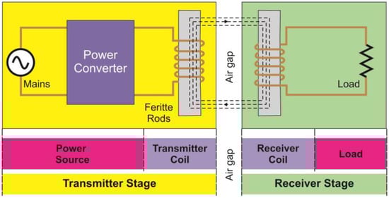
Figure 2.
Schematic of IPT system.
IPT is based on the principle that the magnetic field created by the alternating current applied to the transmitter coil windings induces voltage and current flows in the windings of the receiver coil. For a continuously changing current to pass through the transmitter winding, AC mains voltage is converted to DC voltage with an AC–DC converter. The DC–AC converter topology converts the DC voltage to high-frequency AC voltage. The magnetic field transfers the generated high-frequency voltage to the receiving coil. The voltage induced in the receiving coil causes a current to flow through the coil depending on the load [23,34,35].
The simplified electrical equivalent circuit diagram of the IPT system is given in Figure 3. The transmitter and receiver coils are shown as inductance where LTX is the transmitter coil inductance, RTX is the transmitter coil resistance, LRX is the receiver coil inductance, RRX is the receiver coil resistance, M is the mutual inductance, is the transmitter coil current, is the receiver coil current, RL is the load resistance, and represents the voltage between the transmitter coil terminals.
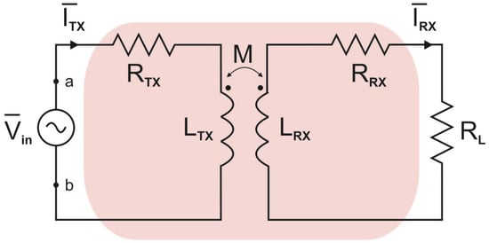
Figure 3.
Simplified electrical equivalent circuit of WPT.
During power transfer, some energy loss occurs because of the resistance in the system. Equation (8) shows the efficiency (η) of the IPT system. ω is the angular frequency. From the electrical equivalent circuit model, the steady-state equations at the transmitter and receiver side are:
From Equation (2), the receiver coil current is:
Substituting Equation (3) into Equation (1) gives:
Total impedance (Zin) seen from the input is given by:
From Equation (5), the reflected impedance (Zref) at the transmitter side is given by:
From Equation (3), the ratio of the transmit and receive coil currents is:
From Equations (5) and (7), efficiency is given by:
where Re{Zin} is the real part of the total impedance, as seen from the input.
As seen from Equation (8), the system’s efficiency depends on the transmitter and receiver coil parameters, load, and M, regardless of ITX and Vin. Inductance appears to be associated with the amount of energy transferred between the receiver and transmitter coils depending on the M between the coils. M can be calculated using the equation given in Equation (9) [36].
where La and Lc indicate self and leakage inductance, respectively. La value is measured from the transmitter coil terminals when the receiver coil terminals are open circuits. Lc is measured from the terminals of these short-circuited coils.
The transmitter and receiver coils are magnetically interconnected by coupling factor k and is between 0 < k < 1. M and La values are used to calculate the coupling factor of the coils. If the windings of the transmitter and receiver coils are identical, LTX = LRX = La. In this case, k can be calculated from Equation (10). As the value of k approaches 1, M will also increase. Thus, higher power transfer to the output is provided.
The circuit diagram of the HB series resonant converter used to apply high-frequency voltage to the transmitter coil is given in Figure 4.
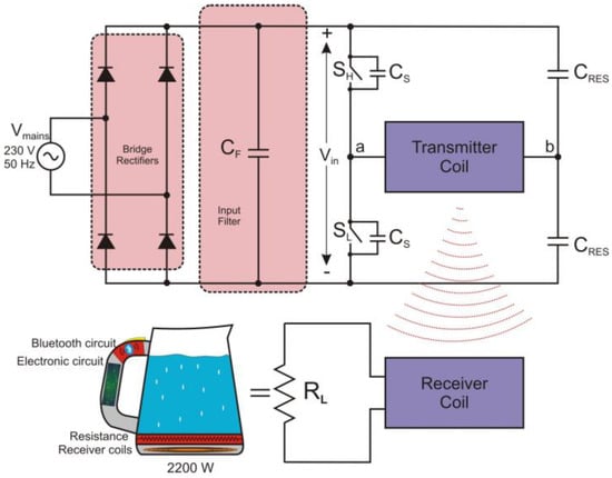
Figure 4.
HB series resonant circuit in IPT system.
DC input voltage is obtained by rectifying and filtering the AC mains voltage (Vmains) with a bridge rectifier. SH and SL are the high-side and low-side power switches, respectively, Cs is the snubber capacitor, and CRES indicates the resonant capacitor. Resonance inductance (LRES) is equal to the inductance at the transmitter terminals. The system’s resonance frequency (fRES) is given in Equation (11), depending on CRES and LRES.
As the switching frequency of the converter fSW approaches the resonant frequency fRES, the current waveform of the coil becomes sinusoidal. In this case, maximum power is transferred to the output. When the system is considered lossless, the input power is equal to the output power. As given in [37], accepting that the system operates at the resonant frequency, the maximum coil current is 4.44 times the mains’ effective current and two times the coil effective current.
In the circuit, a dead time (td) is left between the control signals of the high-side and low-side switches for safety. When the switch is turned off, the coil current starts to pass through the Cs. This process ends when the voltages of the turned-on and turned-off switches reach 0 V and Vin, respectively. After the snubber capacitors are charged/discharged, the coil current starts to pass through the diode. In this case, the charge/discharge time (tc) of Cs is calculated by Equation (12).
To provide zero-voltage switching (ZVS), one of the soft switching methods to minimize switching losses, td must be greater than tc [38].
3. Design Criteria of the System
In SHA’s adaptation of the WPT system, it is not desirable for the new system to change user habits. Therefore, the design must be made considering the operation of the corded electric kettle. The criteria required to operate the existing 2200 W kettle with WPT technology are listed below.
- Changes to be made to the product should not change its characteristics;
- Must be able to operate in a wide AC main voltage range;
- It should be highly efficient according to Ki cordless kitchen standards;
- Must be able to transfer the maximum power value specified in Ki cordless kitchen standards;
- It should also provide low-power transfers during the keep warm function;
- The coupling coefficient between the transmit and receive coils must be high;
- Coil diameters must be compatible with the base diameter of the existing kettle and IH cooktop coils.
4. Design
The proposed system is designed in two parts: magnetic system and power circuit design.
4.1. Magnetic System Design
In the magnetic system design, the inductance value of the coil (LTX = LRX = La), coil diameter, coil height, coil current effective value, coil switching frequency, coil maximum operating temperature, and minimum–maximum air gap are determined [21]. Coil diameters and inductance values depend on the geometry. The effective value of the current affects the current density, that is, the current value passing through 1 mm2. Depending on the current density, the number of wires to be used in the litz wire can be increased, and the cooling design of the coil can be made. Since the frequency affects the penetration depth, the penetration depth should be considered when selecting the wire diameter used in the litz wire. The maximum operating temperature value is important for predicting whether the ferrites used will be saturated. The leakage inductance value and the transferred power change depending on the air gap. The prototype and system design determine the minimum air gap, and the system efficiency determines the maximum value.
In this study, a design will be made in case the transmitter and receiver coils are aligned with each other horizontally and vertically and the number of turns is the same. The system can be considered a transformer with a conversion ratio of 1:1. The coil diameter should not enlarge the dimensions of the product. The surface area should be designed as small as possible so that it does not take up too much space on the counter. The coils were chosen as a 145 mm diameter cylindrical coil used in the existing IH cooktops, considering the dimensions of the existing kettle. The magnetic system is designed to consist of vertically aligned, air-gapped transmitter and receiver coils with a diameter of 145 mm. Litz wire is used in coil windings. The magnetic system is modeled in Maxwell software. The coil specifications used in the model are given in Table 3. Figure 5 shows the model formed by mutually locating the windings of the coils and perfectly aligning the ferrite rods with each other.
Table 3.
Coil Parameters.
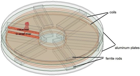
Figure 5.
IPT coil model.
Coil analysis was done by varying the air gap values between the coils. The minimum air gap is 4 mm because of design limitations. The values of self-inductance, mutual inductance, leakage inductance, and coupling factor were determined for the air gap values from 4–8 mm. Using these values, the graphs in Figure 6, Figure 7, Figure 8 and Figure 9 were obtained. The graphs show that the leakage inductance increases with the distance between the coils, and the mutual inductance, self-inductance, and coupling factor decrease. The coils were created according to the parameter values determined in the design and given in Table 3. The realized coils were connected to the prototype device and the measurements were taken.
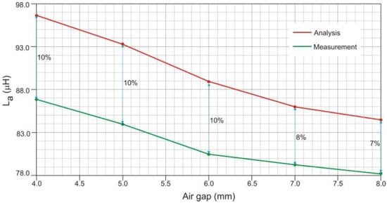
Figure 6.
Self-inductance vs. air gap.
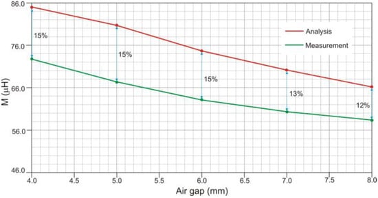
Figure 7.
Mutual inductance vs. air gap.
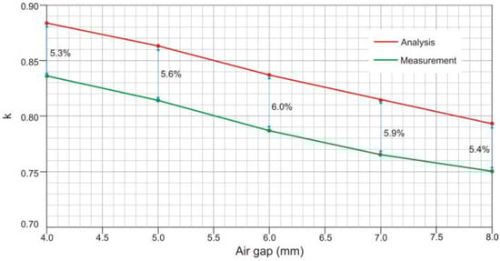
Figure 8.
Coupling factor vs. air gap.
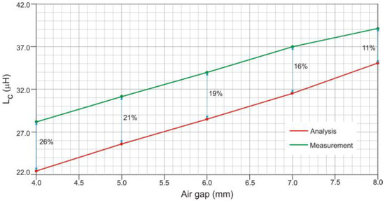
Figure 9.
Leakage inductance vs. air gap.
The values of self-inductance, mutual inductance, and leakage inductance were measured by a Hioki IM3536 LCR meter. These measurements were made for different distances of the air gap between the coils. The measurement results and the % value of the difference between them are added to Figure 6, Figure 7, Figure 8 and Figure 9. Although there are some differences from prototyping, the air-gap-to-inductance relationship is consistent in testing and analysis. As the air gap increases, the self and mutual inductance decreases and the leakage inductance increases.
4.2. Power Circuit and Control Design
In an IPT system, the transmitter coil will be energized with a resonant converter. The designed transmitter coil inductance will be used as the resonance inductance. Since the resonance frequency of the designed SHA is also planned to be used in IH cooktops, it has been chosen to be equal to the cooktop resonance frequency. The resonance frequency and coil inductance are used to determine the resonance capacitors. For the system to operate in the inductive region, the switching frequency of the converter should be chosen higher than the resonance frequency. It should also be greater than 20 kHz, which is the upper limit of the frequency that the human ear can hear. The maximum value of the frequency is determined according to the minimum value of the power to be transferred.
The values obtained from the coil analyzes were used in the power circuit design calculations. By the circuit design criteria, a power circuit design has been made in which WPT is performed. To determine the circuit elements, the maximum input power, the minimum value of the mains voltage, and the resonance frequency are the required values.
It should be able to provide power up to 2200 W, operate in 230 V/50 Hz mains, and tolerate voltage drops in the mains up to 200 V without loss of performance. In addition, it should be able to continue working with a decrease or increase in power up to the minimum and maximum values of 150 V and 260 V, respectively, of the mains voltage.
A 23 kHz resonance frequency value was selected in accordance with the criteria specified in the design. The resonance capacitor value was calculated according to the resonance frequency and transmitter inductance value. The values obtained as a result of the calculation are given in Table 4. The semiconductor device was selected according to the circuit current and voltage values during the maximum power transfer to the output. The FGW40N65WE IGBT semiconductor power device with reverse current diode with resistance values of 650 V and 40 A was selected. To keep the switching losses in the selected IGBTs to a minimum, the ZVS condition must be met. For this reason, the sum of the turn-off delay and fall time during the turn-off process of the IGBT must be smaller than td.
Table 4.
Half-Bridge Series Resonant Converter Design Parameters.
The control of the proposed system consists of two separate parts for the transmitting and receiving stages. However, these stages are not independent of each other. The basic control flow chart is given in Figure 10. As seen from the flow chart, first, it is necessary to wake up the product on the primary side and initiate a low power flow. This way, the communication and control circuit on the secondary side will wake up and start the communication with the primary side. Likewise, this awakening on the secondary side will indicate to the user that the system is ready and that the desired temperature value can be entered. In line with the user request entered through the interface, an evaluation will be made at the receiver part, and the necessary power demand will be made from the transmitter part. It will stop working in the case of no power demand. In addition, the system needs to switch to standby after a certain period when it is detected that it is not working to reduce power consumption, especially in small household appliances. Therefore, depending on the usage situation, waking the system or keeping it in sleep mode should be added to the control.
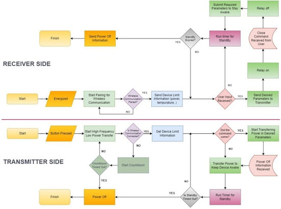
Figure 10.
Operating flow chart of WPT system designed for kettle.
In the proposed system, the circuits in the transmitter and receiver parts operate as slave and master, respectively. The control circuit with a simple microprocessor is built into the kettle handle. The resistance value of the NTC (negative temperature coefficient) element in the water tank is detected with the help of the auxiliary circuit. The microprocessor calculates the temperature value corresponding to the resistance value. After the measurement and calculation, the temperature value of the water is determined. While the temperature value is displayed on the screen on the kettle handle, it also provides interaction with the user. In addition, thanks to this screen and selection buttons, the user can enter the desired temperature value. The desired and current state is stored in the microprocessor here. In the system’s design, the time to reach the demanded temperature value and the power required can be calculated. According to the results, the kettle requests power from the transmitter stage. The microprocessor used here has a wireless communication feature. This calculated power requirement is transmitted to the transmitter side using Bluetooth low energy (BLE). Thus, the system can wake up with a low power requirement at the first energizing. The current reading circuit detects the transmitted power on the receiving coil. This value is compared with the demanded power, and the necessary calibration is undertaken.
The transmitter part manages all the necessary processes to control the resonance circuit and keeps the system’s security under control. It processes the system and limits information at the time of first start-up from the kettle, and the desired power is expected. This power information is monitored at regular intervals and sends the current status to the kettle as a response. Since the kettle is de-energized when it is removed from its place, it cannot demand power from the transmitter side. Thus, in addition to the load-sensing algorithm on the transmitter side, power transmission is interrupted because no signal is sent from the kettle.
At the transmitter side, the peak value of the current is used in power control. When the transmitting side is energized, it detects the zero crossing of the grid and synchronizes. High-frequency PWM (pulse width modulation) drive signals are applied to IGBTs when power demand is received. The HB resonant converter must be applied with a certain dead time between the signals of the high-side and low-side IGBTs. The system starts to operate at the highest frequency with a fixed duty ratio. Then, since the mains’ zero crossing points and frequency are known, the transmitter coil current is read in a certain range in the peak region of the mains voltage. The read and reference values are compared, and PI (proportional–integral) control is applied. In this control, the frequency of the IGBT drive signal is gradually reduced to reach the reference value. The coil current and, accordingly, the transferred power begin to increase. The frequency of the drive signal is changed only at the zero crossing points of the grid. In this way, the peak values on the switch are kept lower by changing the driving signal at the point where the peak value of the coil current is the lowest.
5. System Simulations
The circuit is set up in Simplorer to perform the full simulation of the system. To obtain the dynamic circuit model, the coils’ magnetic model created in Maxwell was transferred to the simulation as a component. The simulation circuit is given in Figure 11. The dynamic model makes it possible to model the power and efficiency in accordance with the air gap and frequency change. To verify the operation of the system, the dynamic model of the circuit was established in ANSYS Simplorer, and the circuit simulation was carried out. The simulation results are given for a fixed operating point, 30 kHz switching frequency, and 7 mm air gap. Figure 12 shows the transmitter and receiver coil currents. The magnetic field created by the current flowing through the transmitting coil induced a voltage on the receiver coil because of a coupling factor. Although the kettle is a resistive characteristic, it also has an inductive component. For this reason, a small phase delay occurs in the current. Figure 13 shows the voltage at the terminals of the transmitter coil and the current waveforms passing through the coil. Here, the inverse of the coil current is seen. There is a phase difference between voltage and current because of the inductive component. Input and transmitted power waveforms are given in Figure 14. There is a slight power difference because of losses in the semiconductor elements and the magnetic circuit. As can be seen from the waveforms, WPT is being performed successfully.
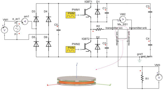
Figure 11.
WPT circuit Simplorer simulation model.
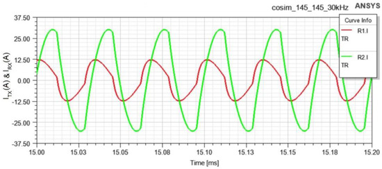
Figure 12.
Current waveforms of transmitter (green) and receiver (red) coils.
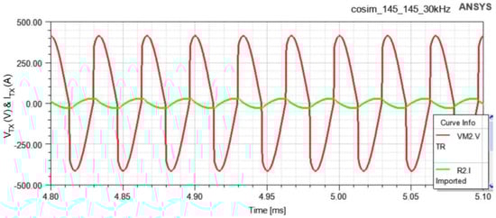
Figure 13.
Voltage (red) and current (green) waveform of the transmitter coil.
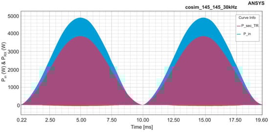
Figure 14.
Transmitter (blue) and receiver (red) coil powers.
6. Experimental Results
Before adopting the kettle to WPT, measurements were made to determine the device’s load characteristics and power values. In Figure 15 and Figure 16, the experimental test setup created for the direct connection of the device to the mains and the measurements taken is given, respectively. In Figure 15, current and voltage measurements are made from the mains by pulling out the ends of the kettle resistance. Ports are placed under a box for security purposes. An oscilloscope and a power analyzer were used for measurements. Mains current and voltage waveforms were measured with the oscilloscope. Then, using the math function of the oscilloscope, the current and voltage values are instantly multiplied to obtain the power variation from the mains. It can be seen from Figure 16 that if the water heater is connected to the 220 V mains, it draws 9.22 A from the mains and the transferred power is approximately 2050 W.
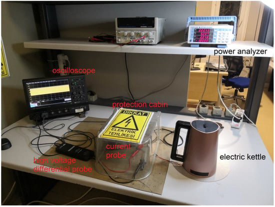
Figure 15.
Test setup for direct connection of electric kettle to the mains.
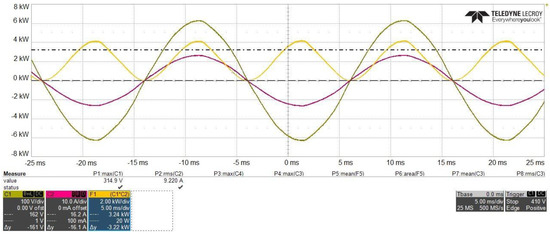
Figure 16.
Voltage (C1, green), current (C2, purple), and power (F1, yellow) of the mains in direct connection.
The power stage was designed to supply the primary coil, and tests were carried out with no load at the receiver terminals. In this case, the microprocessor used in control produces 75 kHz drive signals, the highest frequency value. In addition, the system keeps the drive signals at a low level and operates in the scan state where the internal supply source circuit is active [39]. When the user places the kettle on the transmitter coil, scanning is performed at a switching frequency of 75 kHz. If the load is detected and matched, the frequency is adjusted according to the temperature selected by the user, and the power is increased. Figure 17 shows the mains voltage and current waveforms when the system is in scan mode.
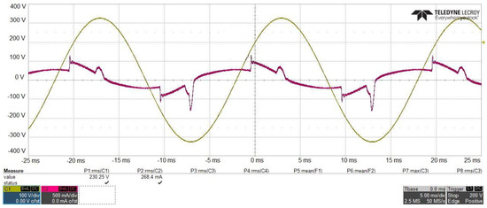
Figure 17.
Voltage (C1, green) and current (C2, purple) of the mains in scan mode.
The receiver coil placed under the kettle is connected to the resistance terminals via a control relay. In Figure 18, the system model with the schematic of the designed electronic PCB board and the measurement points from the system are shown. The Yokogawa WT310 power analyzer used for power measurement is connected to the mains input. To verify the operation of the design, the experimental setup shown in Figure 19 was created. Figure 19 shows the system not placed in a closed box. Here, the transmitting coil connected to the HB inverter is mounted inside the base where it will normally be located, and the receiving coil is placed under the kettle with a 7 mm air gap with the transmitting coil. In this way, measurements can be taken easily from desired points on the system. During the experimental study, the air gap between the coils was kept constant, and measurements were taken from different system points for different power values. Since the coils used in the design are fixed with plastic bodies, the air gap and alignment cannot be changed by the user.
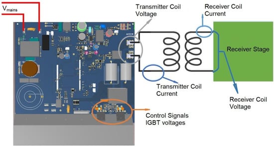
Figure 18.
Electronic PCB board and measuring points.
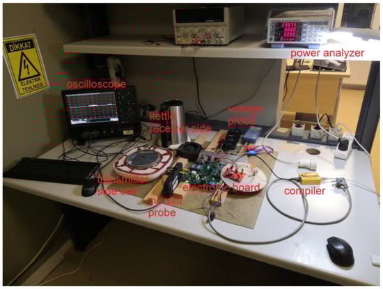
Figure 19.
Experimental test setup of WPT system with electric kettle.
If the WPT system operates at different switching frequencies, the current and voltage waveforms of the mains are given in Figure 20, Figure 21, Figure 22 and Figure 23. The current is measured in reverse so that the waveforms do not overlap.
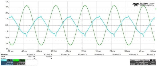
Figure 20.
Mains voltage (C4, green) and current (C3, blue) at 75 kHz.

Figure 21.
Mains voltage (C4, green) and current (C3, blue) at 39 kHz.
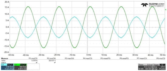
Figure 22.
Mains voltage (C4, green) and current (C3, blue) at 31 kHz.
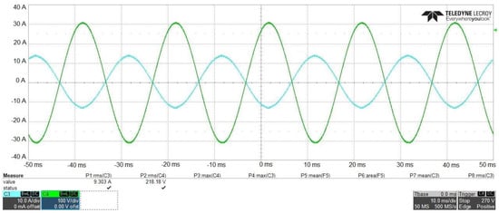
Figure 23.
Mains voltage (C4, green) and current (C3, blue) at 26 kHz.
The power value is adjusted by changing the switching frequency. As the switching frequency approaches the resonant frequency, the power transferred to the load increases in the inductive region. Due to the low value of the input filter capacitor, the input current waveform is close to sinusoidal. Therefore, power-factor correction (PFC) is not required at the circuit input. The voltage and current waveforms of the transmitter coil are given in Figure 24, Figure 25, Figure 26 and Figure 27 for different switching frequencies. It can be seen from the waveforms that the coil current has an inductive characteristic. As the switching frequency approaches the resonant frequency, the current waveform becomes sinusoidal because of the resistance load characteristic.
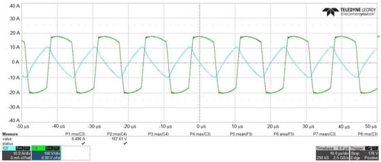
Figure 24.
Transmitter coil voltage (C4, green) and current (C3, blue) at 75 kHz.
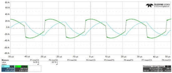
Figure 25.
Transmitter coil voltage (C4, green) and current (C3, blue) at 39 kHz.
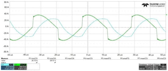
Figure 26.
Transmitter coil voltage (C4, green) and current (C3, blue) at 31 kHz.
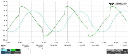
Figure 27.
Transmitter coil voltage (C4, green) and current (C3, blue) at 26 kHz.
The voltage and current waveforms of the receiver coil are given in Figure 28, Figure 29, Figure 30 and Figure 31 for different switching frequencies. Here, the current has an inductive characteristic as it is in the transmitter coil.
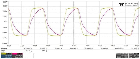
Figure 28.
Receiver coil voltage (C1, green) and current (C2, purple) at 75 kHz.
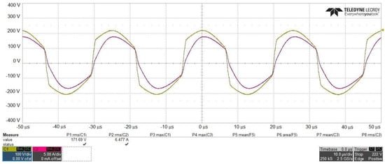
Figure 29.
Receiver coil voltage (C1, green) and current (C2, purple) at 39 kHz.
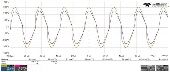
Figure 30.
Receiver coil voltage (C1, green) and current (C2, purple) at 31 kHz.
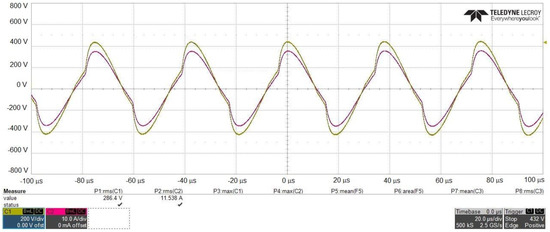
Figure 31.
Receiver coil voltage (C1, green) and current (C2, purple) at 26.
In Figure 32, Figure 33, Figure 34 and Figure 35, IGBT control signals and transmitter coil current waveforms are given for switching frequencies. The dead time between high side and low side switch control signals is approximately 2 µs and constant. The energy stored in the coil is transferred by the diodes in this interval when both switches are in the off state. As a result, the coil current decreases during the dead time. When the control signal of the high-side switch is applied, the body diode of the switch is in the on state because of the direction of the current. When the resonance current direction is changed, a high-side switch is turned on with ZVS. Similarly, it is seen that the low-side switch is turned on with ZVS.
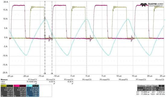
Figure 32.
High-side IGBT control signal (C1, green), low-side IGBT control signal (C2, purple), and transmitter coil current (C3, blue) at 75 kHz.
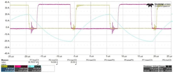
Figure 33.
High-side IGBT control signal (C1, green), low-side IGBT control signal (C2, purple), and transmitter coil current (C3, blue) at 39 kHz.
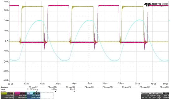
Figure 34.
High-side IGBT control signal (C1, green), low-side IGBT control signal (C2, purple), and transmitter coil current (C3, blue) at 31 kHz.
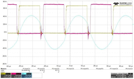
Figure 35.
High-side IGBT control signal (C1, green), low-side IGBT control signal (C2, purple), and transmitter coil current (C3, blue) at 26 kHz.
Figure 36 shows the test system for efficiency measurement. Here, the alignment was provided with the plastic parts that provide the horizontal alignment of the transmitter and receiver coils. The transmitted power was controlled with the help of electronic boards. The efficiency value was obtained with the measurements taken from the input and output points of the system. The harmonic measurements of the designed system were made according to the class D limits of the IEC 61000-3-2 standard [40]. The harmonic analysis of the current drawn from the mains is given in Figure 37. The first 40 harmonics of the 50 Hz current are shown here, in addition to the mains voltage and current. Each of these harmonics is listed in the lower left corner of Figure 37, along with its level, frequency, and conformity to the standard. The harmonics value of the current drawn from the mains was below the value determined by the standard. In addition, the power factor was measured as approximately 1. The system’s efficiency was calculated using the input and output power values measured at different switching frequencies. The efficiency curve is given in Figure 38. The system efficiency was over 90% and approximately stable over the wide power range.
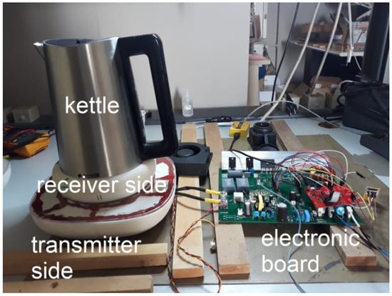
Figure 36.
Test setup of kettle for efficiency measurement.
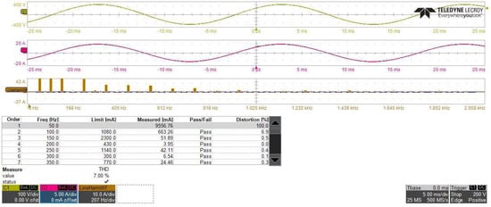
Figure 37.
Harmonic measurement of system.
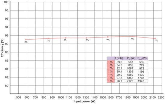
Figure 38.
System efficiency.
7. Conclusions
In this article, a wireless power transfer system without compensation elements and with a wide range of power transfer features for small household appliances was presented. Coils with a high coupling coefficient are used in the proposed system. It has been seen that the obtained results are compatible with the simulation results, and the power is successfully transferred to the load. The efficiency is above the 90% specified in the Ki cordless kitchen standard at high powers. By using SiC devices as power switches in the circuit, losses in the system and cooler sizes can be reduced and higher efficiency can be achieved. Wireless operation of kitchen appliances using existing IH cooktops is becoming important for both academia and industry. This study will contribute to the design of wireless SHAs that are expected to be used in induction cookers in the near future.
Author Contributions
Conceptualization, C.S. and N.A.; methodology, C.S. and N.A.; validation, C.S. and N.A.; investigation, C.S. and N.A.; writing—original draft, C.S. and N.A. All authors have read and agreed to the published version of the manuscript.
Funding
This research received no external funding.
Data Availability Statement
No new data were created.
Acknowledgments
The laboratory side of this research is supported by Arçelik Global R&D.
Conflicts of Interest
The authors declare no conflict of interest.
References
- He, H.; Wang, S.; Liu, Y.; Jiang, C.; Wu, X.; Wei, B.; Jiang, B. Maximum Efficiency Tracking for Dynamic WPT System Based on Optimal Input Voltage Matching. IEEE Access 2020, 8, 215224–215234. [Google Scholar] [CrossRef]
- Shu, X.; Xiao, W.; Zhang, B. Wireless Power Supply for Small Household Appliances Using Energy Model. IEEE Access 2018, 6, 69592–69602. [Google Scholar] [CrossRef]
- Pedder, D.; Brown, A.; Skinner, J. A contactless electrical energy transmission system. IEEE Trans. Ind. Electron. 1999, 46, 23–30. [Google Scholar] [CrossRef]
- Covic, G.A.; Boys, J.T. Inductive Power Transfer. Proc. IEEE 2013, 101, 1276–1289. [Google Scholar] [CrossRef]
- Jiang, Y.; Zhang, B.; Zhou, J. A Fractional-Order Resonant Wireless Power Transfer System with Inherently Constant Current Output. IEEE Access 2020, 8, 23317–23323. [Google Scholar] [CrossRef]
- Qi, C.; Lang, Z.; Su, L.; Chen, X.; Miao, H. Model Predictive Control for a Bidirectional Wireless Power Transfer System with Maximum Efficiency Point Tracking. In Proceedings of the 2019 IEEE International Symposium on Predictive Control of Electrical Drives and Power Electronics (PRECEDE 2019), Quanzhou, China, 31 May–2 June 2019; pp. 1–5. [Google Scholar]
- Patil, D.; McDonough, M.K.; Miller, J.M.; Fahimi, B.; Balsara, P.T. Wireless Power Transfer for Vehicular Applications: Overview and Challenges. IEEE Trans. Transp. Electrif. 2018, 4, 3–37. [Google Scholar] [CrossRef]
- Abe, H.; Sakamoto, H.; Harada, K. A noncontact charger using a resonant converter with parallel capacitor of the secondary coil. IEEE Trans. Ind. Appl. 2000, 36, 444–451. [Google Scholar] [CrossRef]
- Mayordomo, I.; Dräger, T.; Spies, P.; Bernhard, J.; Pflaum, A. An overview of technical challenges and advances of inductive wireless power transmission. Proc. IEEE 2013, 101, 1302–1311. [Google Scholar] [CrossRef]
- Kracek, J.; Svanda, M. Analysis of Capacitive Wireless Power Transfer. IEEE Access 2019, 7, 26678–26683. [Google Scholar] [CrossRef]
- Nguyen, M.T.; Nguyen, C.V.; Truong, L.H.; Le, A.M.; Quyen, T.V.; Masaracchia, A.; Teague, K.A. Electromagnetic Field Based WPT Technologies for UAVs: A Comprehensive Survey. Electronics 2020, 9, 461. [Google Scholar] [CrossRef]
- Hsieh, Y.-C.; Lin, Z.-R.; Chen, M.-C.; Hsieh, H.-C.; Liu, Y.-C.; Chiu, H.-J. High-Efficiency Wireless Power Transfer System for Electric Vehicle Applications. IEEE Trans. Circuits Syst. II Express Briefs 2017, 64, 942–946. [Google Scholar] [CrossRef]
- Mude, K.N.; Aditya, K. Comprehensive review and analysis of two-element resonant compensation topologies for wireless inductive power transfer systems. Chin. J. Electr. Eng. 2019, 5, 14–31. [Google Scholar] [CrossRef]
- Lin, J.C. Safety of Wireless Power Transfer. IEEE Access 2021, 9, 125342–125347. [Google Scholar] [CrossRef]
- Van Mulders, J.; Delabie, D.; Lecluyse, C.; Buyle, C.; Callebaut, G.; Van der Perre, L.; De Strycker, L. Wireless Power Transfer: Systems, Circuits, Standards, and Use Cases. Sensors 2022, 22, 5573. [Google Scholar] [CrossRef] [PubMed]
- Topuz, N.E.; Dawood, K.; Kaya, U.; Odabas, G.; Komurgoz, G. Electromagnetic and Thermal Analysis of a Domestic Induction Cooker Coil. In Proceedings of the 2019 4th International Conference on Power Electronics and Their Applications (ICPEA 2019), Elazig, Turkey, 25–27 September 2019; pp. 1–5. [Google Scholar] [CrossRef]
- Shevchenko, V.; Husev, O.; Strzelecki, R.; Pakhaliuk, B.; Poliakov, N.; Strzelecka, N. Compensation Topologies in IPT Systems: Standards, Requirements, Classification, Analysis, Comparison and Application. IEEE Access 2019, 7, 120559–120580. [Google Scholar] [CrossRef]
- Wang, Z.; Li, Y.; Sun, Y.; Tang, C.; Dai, X. An Efficiency Optimization Strategy with Segmented Optimal Frequency in the Common Inductive Power Transfer Platform. Inf. Technol. J. 2013, 12, 1512–1521. [Google Scholar] [CrossRef]
- Wu, L.; Zhang, B.; Jiang, Y.; Zhou, J. A Robust Parity-Time-Symmetric WPT System with Extended Constant-Power Range for Cordless Kitchen Appliances. IEEE Trans. Ind. Appl. 2022, 58, 1179–1189. [Google Scholar] [CrossRef]
- Tritschler, J.; Goeldi, B.; Reichert, S.; Griepentrog, G. Comparison of different control strategies for series-series compensated inductive power transmission systems. In Proceedings of the 2015 17th European Conference on Power Electronics and Applications (EPE’15 ECCE-Europe 2015), Geneva, Switzerland, 8–10 September 2015; pp. 1–8. [Google Scholar] [CrossRef]
- Sezer, C.; Odabas, G.; Sinirlioglu, S.; Kaya, B.; Altintas, N. Modeling of WPT System for Small Home Appliances. In Proceedings of the 14th Regional Conference on Electrical and Electronics Engineering (RC-EEE 2021), Bangkok, Thailand, 3 December 2021; pp. 243–247. [Google Scholar] [CrossRef]
- Wilamowski, B.M.; Irwin, J.D. The Industrial Electronics Handbook Power Electronics and Motor Drives; CRC Press Taylor and Francis Group: Boca Raton, FL, USA, 2011. [Google Scholar]
- Itraj, M.; Ettes, W. Topology study for an inductive power transmitter for cordless kitchen appliances. In Proceedings of the IEEE PELS Workshop on Emerging Technologies: Wireless Power Transfer (Wow), Seoul, Korea, 15–19 November 2018; pp. 1–8. [Google Scholar] [CrossRef]
- Luo, S.; Zhang, Z.; Li, G.; Yao, Z.; Zhang, X.; Ma, H. A Primary Shunt Inductor Compensated Inductive Power Transfer System with Natural ZVS for Battery Charging Application. In Proceedings of the 2021 IEEE 1st International Power Electronics and Application Symposium (PEAS 2021), Shanghai, China, 13–15 November 2021; pp. 1–6. [Google Scholar] [CrossRef]
- WPC. Ki Cordless Kitchen: From Concept to Industry Standard; White Paper; Wireless Power Consortium: Piscataway, NJ, USA, 2019; Available online: https://www.wirelesspowerconsortium.com/data/downloadables/2/3/7/5/ki-cordless-kitchen-white-paper-september-2019.pdf (accessed on 12 May 2022).
- Vreede, J. The Wireless Kitchen: Introducing Inductive Power Transfer in the Kitchen Environment. Master’s Thesis, Department of Electronic Engineering, Delft University of Technology, Delft, The Netherlands, 2013. [Google Scholar]
- WPC. Cordless Kitchen Appliances: A Powerful New Kitchen Concept; White Paper; Wireless Power Consortium: Piscataway, NJ, USA, 2013; Available online: https://www.wirelesspowerconsortium.com/data/downloadables/1/1/0/5/201304-white-paper-cordless-kitchen-appliances.pdf (accessed on 12 May 2022).
- Plumed, E.; Lope, I.; Acero, J.; Burdio, J.M. Domestic Induction Heating System with Standard Primary Inductor for Reduced-Size and High Distance Cookware. IEEE Trans. Ind. Appl. 2022, 58, 7562–7571. [Google Scholar] [CrossRef]
- Plumed, E.; Acero, J.; Lope, I.; Burdío, J.M. Design methodology of high performance domestic induction heating systems under worktop. IET Power Electron. 2020, 13, 300–306. [Google Scholar] [CrossRef]
- Yin, N.X.; Saat, S.; Husin, S.H.; Yusop, Y.; Awal, M.R. The design of IPT system for multiple kitchen appliances using class E LCCL circuit. Int. J. Electr. Comput. Eng. 2020, 10, 3483–3491. [Google Scholar] [CrossRef]
- Xia, Z.; Li, J.; Li, S.; Wan, J.; Wu, L.; Wang, Z.; Wang, S. A Wireless Induction Heating Rice Cooker with SCCC Compensation Network. In Proceedings of the International Conference on Electrical Machines, Valencia, Spain, 5–8 September 2022; pp. 1–5. [Google Scholar] [CrossRef]
- Plumed, E.; Lope, I.; Acero, J.; Burdio, J.M. Inductor System Evaluation for Simultaneous Wireless Energy Transfer and Induction Heating. In Proceedings of the IECON 2018—44th Annual Conference of the IEEE Industrial Electronics Society, Washington, DC, USA, 21–23 October 2018; pp. 3509–3514. [Google Scholar] [CrossRef]
- Nutwong, S.; Sangswang, A.; Naetiladdanon, S.; Mujjalinvimut, E. A Novel Output Power Control of Wireless Powering Kitchen Appliance System with Free-Positioning Feature. Energies 2018, 11, 1671. [Google Scholar] [CrossRef]
- Hui, S.Y.R.; Zhong, W.; Lee, C.K. A Critical Review of Recent Progress in Mid-Range Wireless Power Transfer. IEEE Trans. Power Electron. 2013, 29, 4500–4511. [Google Scholar] [CrossRef]
- Zhang, Z.; Pang, H.; Georgiadis, A.; Cecati, C. Wireless Power Transfer—An Overview. IEEE Trans. Ind. Electron. 2019, 66, 1044–1058. [Google Scholar] [CrossRef]
- Hurley, W.; Wilcox, D. Calculation of leakage inductance in transformer windings. IEEE Trans. Power Electron. 1994, 9, 121–126. [Google Scholar] [CrossRef]
- Sinirlioglu, S.; Aksoy, I. Independent from cookware ferromagnetic characteristics transferring maximum power each cookware on domestic induction cooktops. In Proceedings of the National Conference on Electrical, Electronics and Biomedical Engineering (ELECO), Bursa, Turkey, 1–3 December 2016; pp. 382–386. [Google Scholar]
- Li, S.; Mi, C.C. Wireless Power Transfer for Electric Vehicle Applications. IEEE J. Emerg. Sel. Top. Power Electron. 2015, 3, 4–17. [Google Scholar] [CrossRef]
- Wang, Z.-H.; Li, Y.-P.; Sun, Y.; Tang, C.-S.; Lv, X. Load detection model of voltage-fed ınductive power transfer system. IEEE Trans. Power Electron. 2013, 28, 5233–5243. [Google Scholar] [CrossRef]
- IEC 61000-3-2; Electromagnetic Compatibility (EMC) Limits. Limits for Harmonic Current Emissions (Equipment Input Current ≤16 A Per Phase). IEC: Geneva, Switzerland, 2020.


Disclaimer/Publisher’s Note: The statements, opinions and data contained in all publications are solely those of the individual author(s) and contributor(s) and not of MDPI and/or the editor(s). MDPI and/or the editor(s) disclaim responsibility for any injury to people or property resulting from any ideas, methods, instructions or products referred to in the content. |
© 2023 by the authors. Licensee MDPI, Basel, Switzerland. This article is an open access article distributed under the terms and conditions of the Creative Commons Attribution (CC BY) license (https://creativecommons.org/licenses/by/4.0/).