
PbLi/Water Reaction: Experimental Campaign and Modeling Advancements in WPBB EUROfusion Project

 , , ,
, , ,  , ,
, ,  , , , and
Abstract
:1. Introduction
- The pressure transient, governed by mixing and pressurization, which might exceed design limits;
- The chemical reaction contributing to pressure and temperature increases, which might generate a more serious system condition;
- The H2 production, which might represent a potential source of energy;
- The release of radioactive products.
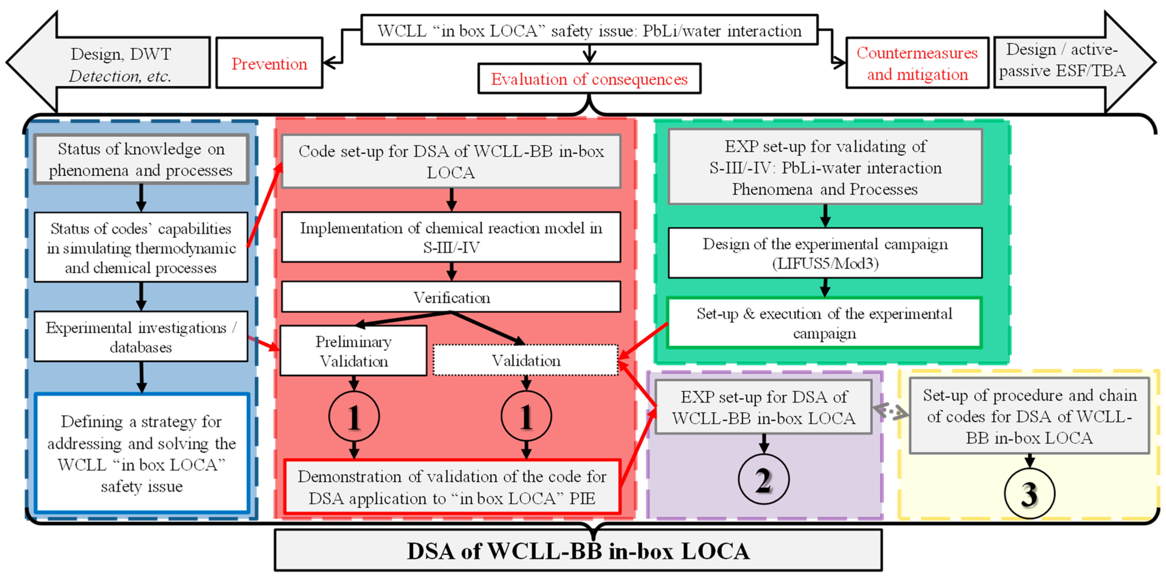
- The set-up and qualification of a numerical tool for predicting PbLi/water interaction. This requires code model improvements [7,8], the extension of the available (to date) experimental database [9,10,11,12], and validation activities [13,14,15,16], carried out during FP8 in separate effect test facility LIFUS5/Mod3;
- The addressing of postulated in-box LOCA events by means of an approach that permits prevention of the occurrence, evaluation of the consequences, and investigation of countermeasures to mitigate the transient. This last point requires extensive numerical simulations and appropriate tools, i.e., the development of a coupling technique to perform transient analyses considering the chemical, thermo-hydraulic, and structural effects due to PbLi/water interaction [17,18,19,20,21] and numerical code to expand the simulation capabilities in fusion applications [22,23], validated against Integral Test Facility experiments [24] currently in progress as part of the FP9 Project.
2. Materials and Methods
3. Results
3.1. Status of Knowledge on Phenomena and Processes
- Small-scale experiments highlighted that the interaction can be divided into two processes: (1) a short-time process caused by thermal interaction and (2) a long-time process due to chemical reaction. Two key parameters influence the severity of the interaction: the fragmentation and the chemical reaction;
- The favorable chemical reaction is the one forming LiOH. In fact, if H2O excesses, a secondary reaction between Li2O and H2O occurs and, therefore, the stable product is LiOH. At the same time, if the temperature of the reaction zone is higher than 450 °C, the stable product is Li2O;
- BLAST and LIFUS5 provided larger-scale data showing the same phenomenological subdivisions of the transient and the relevance of system compressibility (i.e., system layout);
- BLAST and LIFUS5 experimental tests permit the investigation of the phenomenology connected to PbLi/water interaction but they are not suitable to perform code validation because of the poorly defined BIC, missing documentation, and lack of experimental data on injected water and hydrogen produced by the reaction;
- The standard version of the SIMMER-III code, available and previously applied to BLAST and LIFUS5 post-tests, reasonably predicted the experimental pressure trends. However, it is worth underlining that the simulations were performed a posteriori, since an engineering approach was used, based on the knowledge of the pressure inside the reaction vessel. Therefore, the code in its standard version does not have predictive capabilities and it is not applicable to the deterministic safety analysis of WCLL BB in-box LOCA.
3.2. Code Set-Up for WCLL-BB in-Box LOCA: SIMMER Model Implementation, Verification, and Preliminary Validation
- The post-test analyses and sensitivity calculations of all LIFUS5 tests highlighted open issues of experimental data (i.e., the injected mass of water calculated by experimentalists a posteriori and reported in the literature). Moreover, the analyses permitted the improvement of the knowledge of test execution and operative conditions (i.e., the injected pressure trend and the pressure at which the injector cap breaks, which do not correspond to design specifications);
- The correct knowledge of initial and boundary conditions affects the SIMMER code results. Nevertheless, the code demonstrated promising capability in predicting phenomena connected with PbLi/water interaction, considering also the chemical reaction and hydrogen production;
- Post-tests and sensitivity analyses of all LIFUS5 tests highlighted the importance of jet-breaking modeling, affected by users’ choices and experiences combined with a lack of needed geometrical information. In particular, the parameters that affect the code results are connected with the knowledge of initial and boundary conditions (i.e., the pressure trend imposed at the injector, the temperature of the injected water, and the free gas volume in the expansion vessel), with code models (i.e., predominant reaction and kinetics velocity), and with nodalization and user choices (i.e., the U-tube mock-up model which is responsible for breaking the water jet). Moreover, interaction phenomena are extremely complex to simulate because they are affected by a large number of parameters (i.e., interfacial area, dimensions of the vapor bubble, HTC, and fragmentation mode due to the jet-breaking). The results are strongly affected by users’ choices and experiences combined with a lack of needed geometrical features;
- Specific outcomes from the post-test analyses performed by the SIMMER code highlighted the transient division into the following three phenomenological windows: Phase 1, characterized by coolant flashing and reaction vessel pressurization; Phase 2, characterized by expansion vessel pressurization; and Phase 3, characterized by system pressure equilibrium. During Phase 1, the SIMMER-III code predicts very well the first pressure peak due to water flashing, and the pressure trend is qualitatively in line with the experimental results. Some differences occur during Phase 2; indeed, the code calculates an anticipated onset of expansion vessel pressurization. This behavior is affected by the fragmentation model. The code results are satisfactory also during Phase 3. From the qualitative behavior of the temperature trends, SIMMER-III reasonably predicts the experimental results. Indeed, the code correctly predicts the zones where the temperatures are higher, i.e., the expansion vessel and zone 1 of the mock-up. However, the temperatures are underestimated in the reaction vessel and overestimated in the expansion vessel. These differences are connected with modeling issues, i.e., the accurate representation of the U-tubes and, therefore, the prediction of coolant fragmentation during injection;
- Comparing SIMMER-III with SIMMER-IV results, a different pressurization trend is evidenced due to a lower hydrogen generation predicted by SIMMER-IV. The reasons are twofold: (1) SIMMER-IV calculates different binary contact areas between water in vapor or in liquid phase, (2) SIMMER-IV calculates frozen PbLi, which does not take part in the chemical reaction. The latter aspect is coherent with the experimental and calculated temperature trends, correctly evaluated by SIMMER-IV.
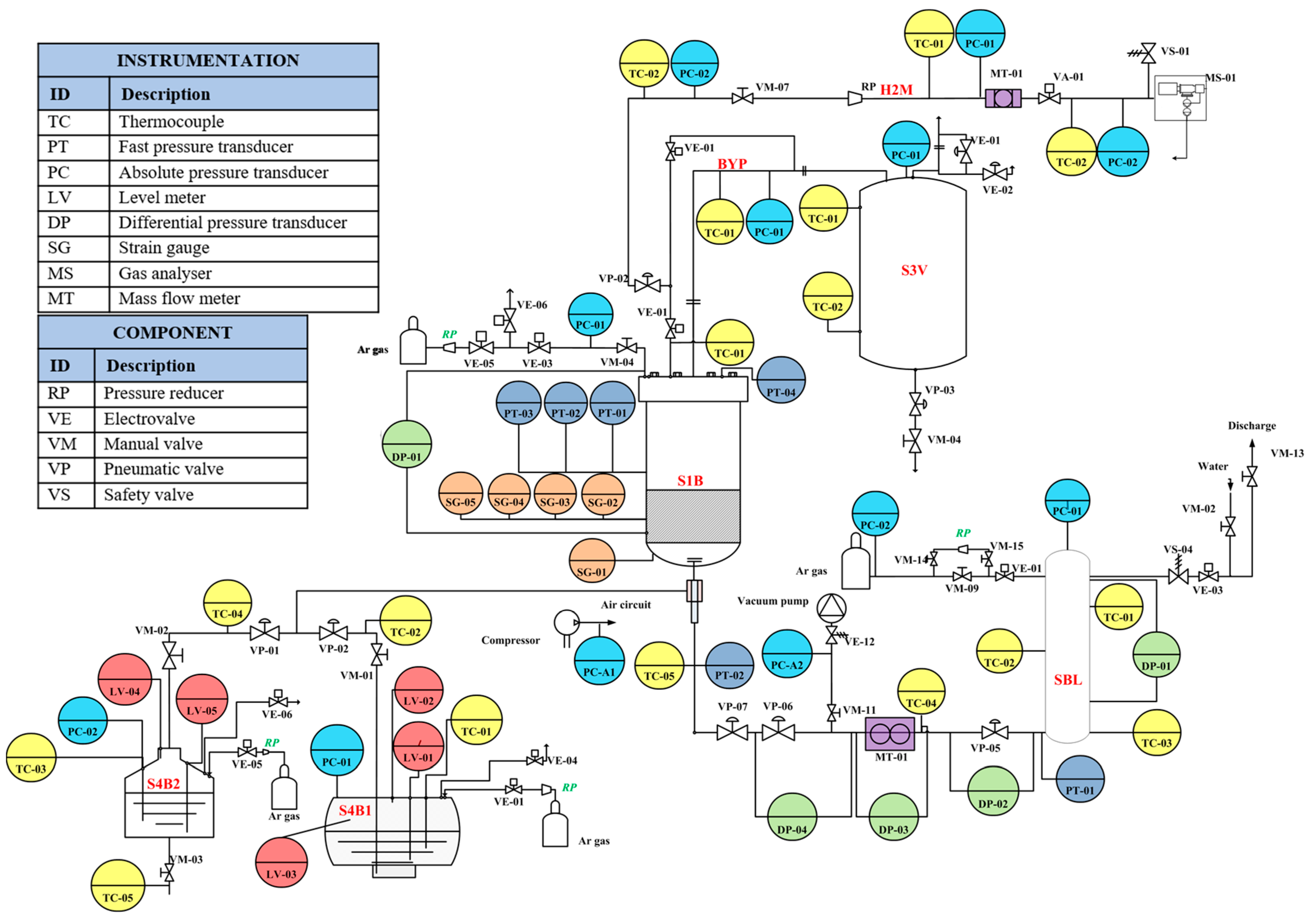
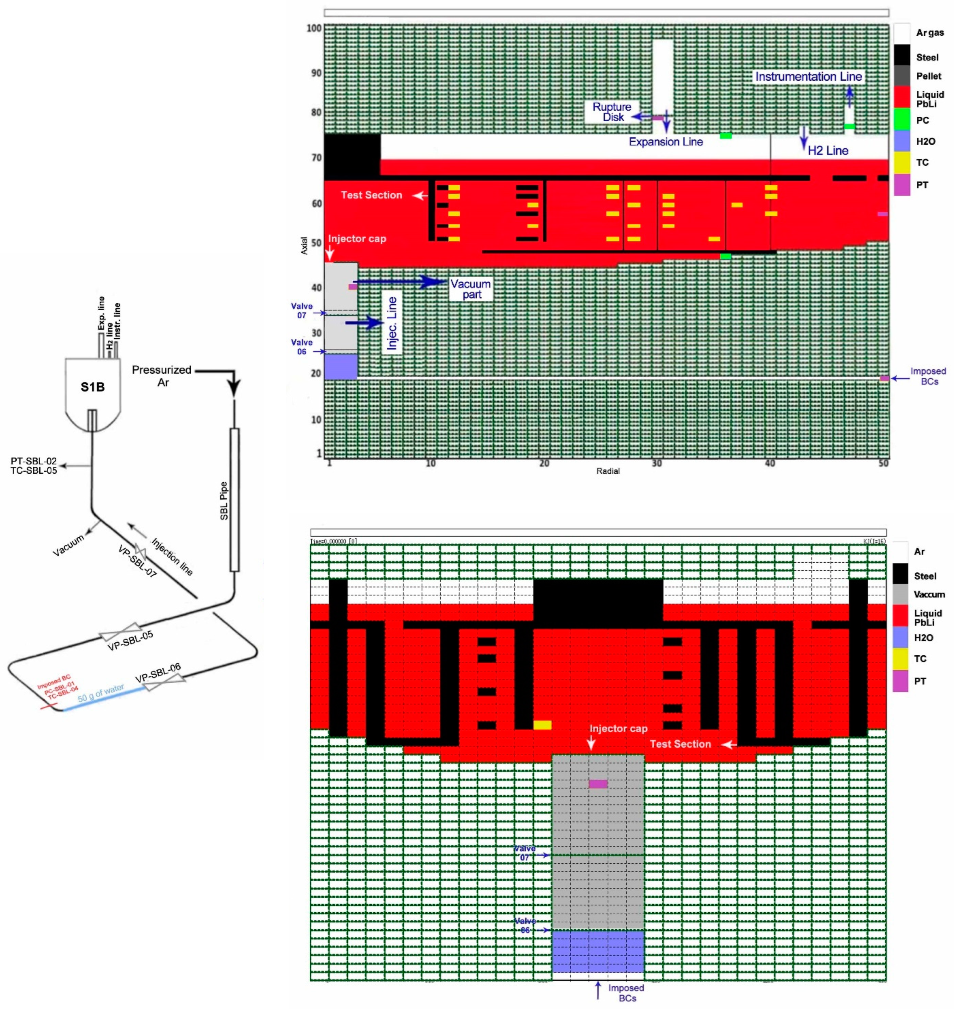
3.3. LIFUS5/Mod3 Experimental Facility for Validating SIMMER Code
- Reaction vessel S1B where the reaction between liquid PbLi and water occurs;
- Water storage and injection line;
- Safety expansion vessel S3V which is connected to S1B with two rupture disks;
- PbLi storage tanks S4B1 and S4B2 for fresh and exploited alloy;
- Hydrogen extraction line.
- Pressurization of water injection line, from pressure rise in injection line to rupture of the cap (from start of the transient to start of the injection);
- Water–PbLi interaction, from start of the injection to end of the injection. Considering the phenomena occurring in this phase, it can be divided in three subphases:
- Flashing of injected water, from the cap rupture to ending of first pressure peaks;
- Thermodynamic interaction, from ending of first peaks to start of increase in temperature;
- Chemical interaction, from start of increase in temperature to the end of the injection.
- Ending phase, from the end of the injection to the end of the transient.
- The influence on the compressibility of the system is confirmed, due to the relatively elastic response depending on the volume of cover gas present in the reaction vessel;
- The flashing of the water jet and its expansion upwards and outwards led to a decrease in temperature inside the melt;
- The increase in temperature is due to the chemical reaction occurring between PbLi and water, at the interface between the two fluids;
- The time window is confirmed, where the thermodynamic interaction is relevant in the first hundreds of milliseconds after the injection, while the chemical interaction becomes significant following the reduction in thermodynamic interactions, causing an increase in temperature and generation of hydrogen;
- Some phenomena connected to the interaction are still under investigation, i.e., the influence of the chemical reaction in the transient. Even though the first pressure peak is due to the flashing of the water inside the melt, thus mainly being a thermodynamic process, the chemical reaction would, in principle, affect the amplitude of the peak. It would be useful to investigate this phenomenon by performing experiments with different liquid metals (LBE or depleted PbLi). Moreover, the chemical reaction is confirmed to be a secondary process and, therefore, it would be useful to perform experiments with longer injection times;
- The kinetics of the reaction and the properties of the chemical products (i.e., Li2O and LIOH) are still missing information. These data are needed in order to have full knowledge of the interaction phenomena and must be implemented into the numerical codes as part of the validation process.
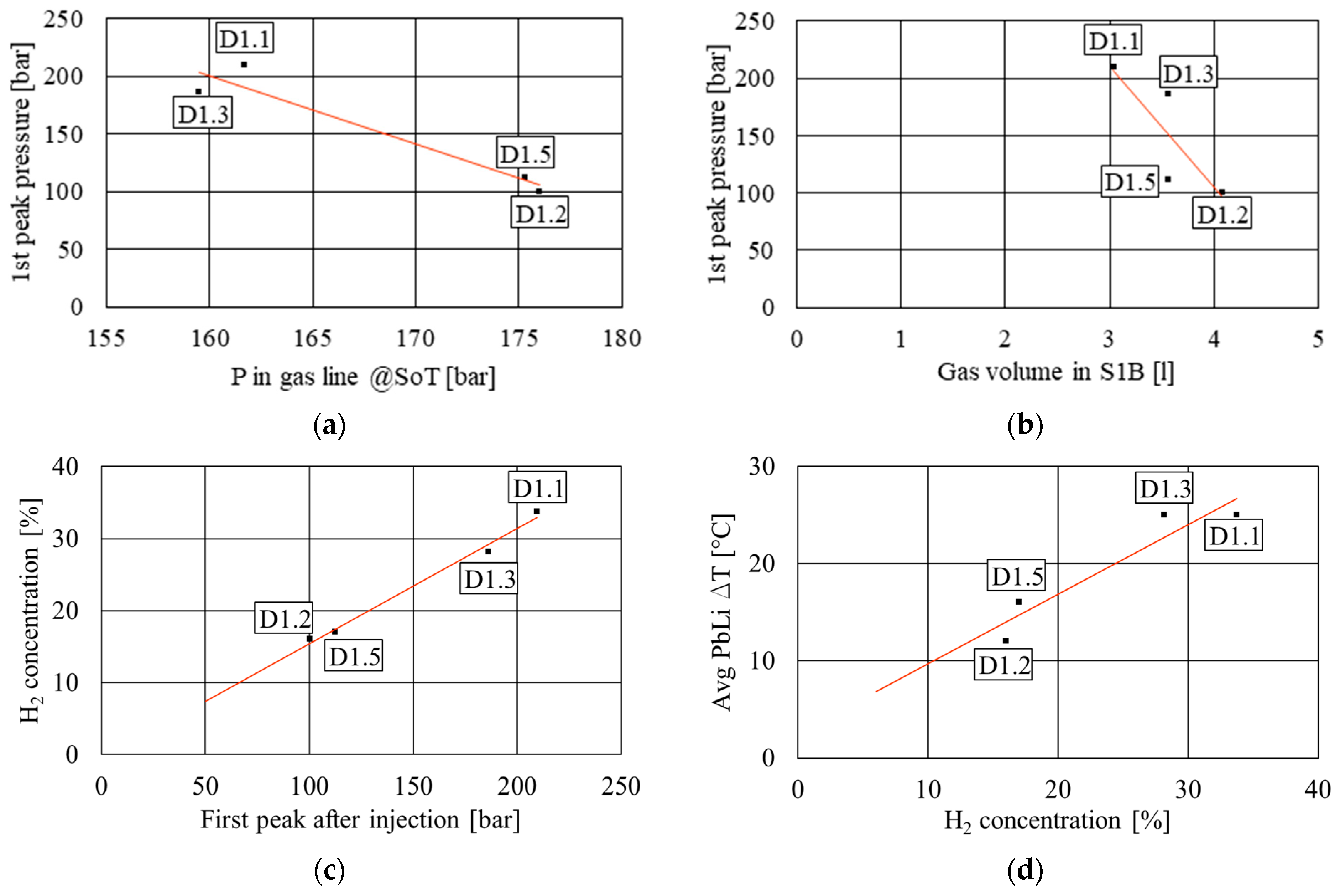
- From the analysis of the Series D1.# tests, executed as a series of repetitions of test #1, with the main goal of investigating the reliability of the experimental data and the repeatability of the test, four main correlations arise:
- ○
- An inverse correlation between the pressure in the SBL gas line and the first peak pressure after the injection (Figure 3a). This inverse correlation might exist due to a higher pressure in the gas line at the beginning of the test which would keep the water in a more subcooled condition, diminishing its capacity for flashing after being injected inside the PbLi;
- ○
- An inverse correlation between the volume of free gas inside vessel S1B and the first peak pressure (Figure 3b). This phenomenon might be associated with the fact that the free volume inside the vessel can compress and absorb the pressure wave caused by the water flashing, as proposed in the previous sections;
- ○
- A direct correlation between the first peak pressure and the H2 concentration (Figure 3c). This correlation is probably associated with the increased contact area between water and PbLi when the jet of water can flash strongly and penetrate deeper into the alloy;
- ○
- A direct correlation between H2 concentration and PbLi temperature variation (Figure 3d). This correlation is quite simple to explain, since a higher H2 production (and, thus, concentration) is associated with a larger energy release due to the chemical reaction and, thus, to an increase in the temperature variation between the initial and final conditions of the PbLi.
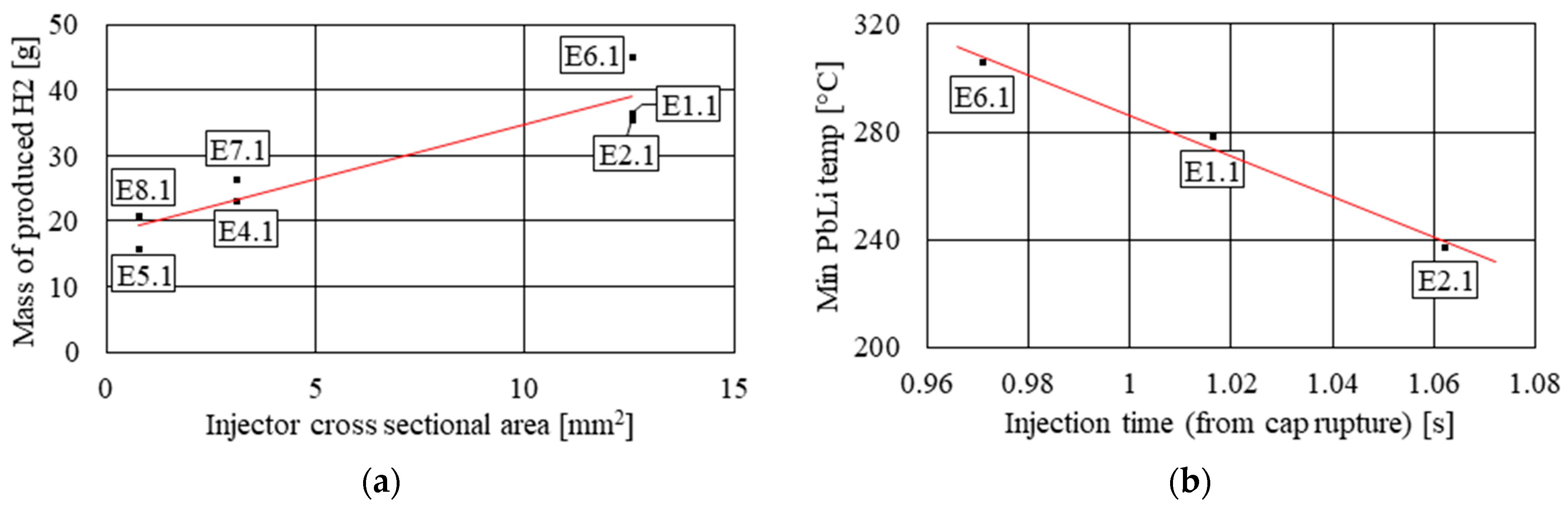
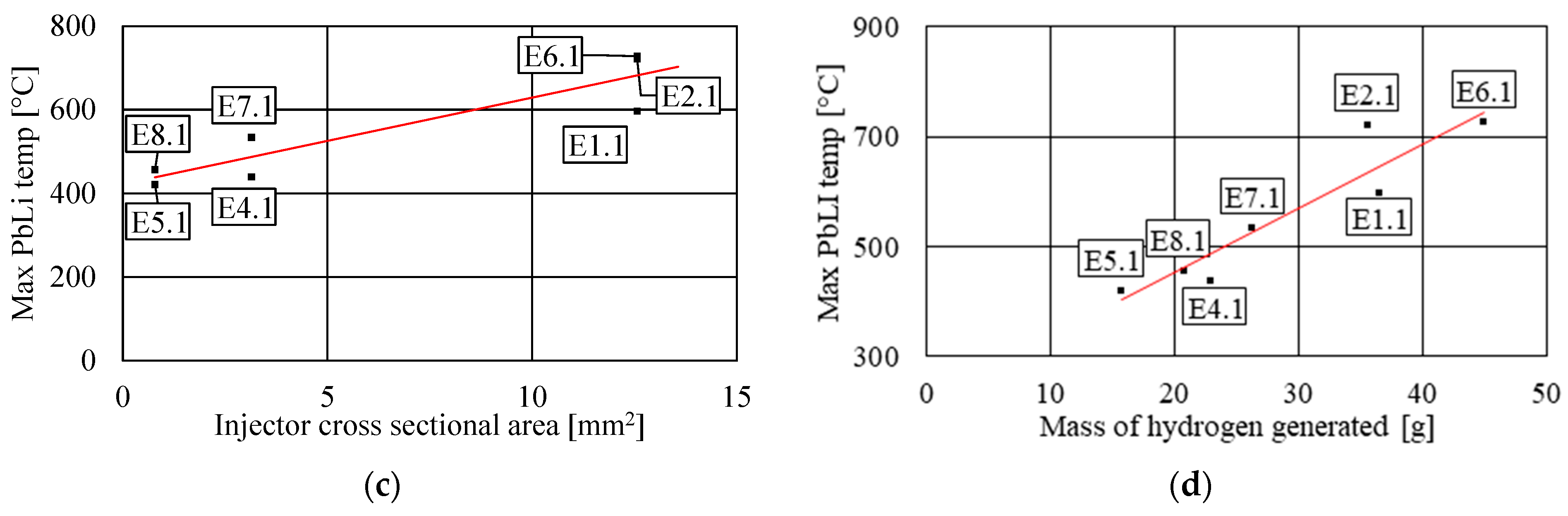
- From the analysis of Series E tests, various relations between important parameters were found:
- ○
- A correlation between the mass of hydrogen produced by the reaction and the injector’s cross-sectional area. This correlation is shown in Figure 4a. Here, we can see how higher injector cross-sectional areas correspond to a higher production of hydrogen. This is partially related to the fact that higher cross-sectional areas are associated with a greater amount of water injected into the vessel, but the different spreading of the jet inside the alloy might also play a role in the amount of water that is able to react;
- ○
- A correlation between the injection time and the minimum PbLi temperature reached during the injection. Figure 4b shows how the minimum temperature registered during the injection phase is related to the injection time. However, only three of the eight tests report this data. These tests are the same as those during which the rupturing of the protection disk happens, thus suggesting that the drop in pressure and the consequent water flashing cause a cooling effect of the PbLi alloy. Longer injection times, as shown in the graph, are associated with a longer flashing phase of the water and, thus, a deeper cooling of the alloy, before the chemical reaction takes over;
- ○
- A correlation between the injector’s cross-sectional area and the maximum PbLi temperature reached during the injection. Figure 4c shows the relation that subsists between the maximum temperature of the PbLi reached during the injection and the cross-sectional area of the injector. This might be explained by considering that a higher cross-sectional area corresponds to a higher mass of injected water and, thus, a greater energy release through the chemical reaction. However, we do not see the same correlation between the injector’s cross-sectional area and mass of water injected. This suggests that the peak temperature is not solely related to the absolute amount of water injected, but mostly to the shape of the jet during the injection. Thus, the correlation between the maximum PbLi temperature and the injector’s cross-sectional area can be associated with the spread of the jet and, thus, with a higher localized reaction rate, which raises the temperature of the system in small-volume regions. This local rise is then recorded by the single thermocouples, while the average variation is recorded by the remaining ones;
- ○
- A correlation between the mass of hydrogen generated and the maximum PbLi temperature reached during the injection. Figure 4d shows the existing correlation between the mass of hydrogen produced during the injection of water and the maximum temperature reached by the PbLi alloy. From this graph, it is evident that the main contributor to the overall energy release inside the vessel is the chemical reaction between the two components.
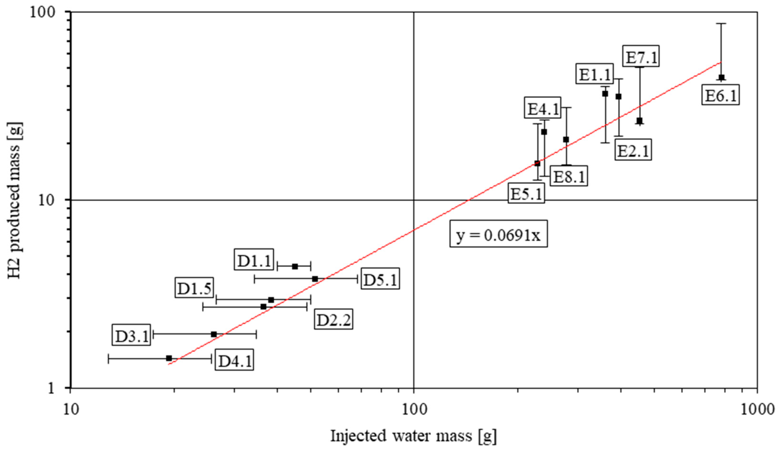
- In the last analysis, all the data from both Series D and E were utilized. The objective is to understand the estimation of the reaction ratio between path A (LiOH formation) and path B (Li2O formation). The result is shown in Figure 5. The figure includes a scatter plot of the H2 and water mass for each test, including theoretical estimations. The scales are log–log to group the different tests, for which the varying amounts of water and hydrogen produced would stretch the data and make them less readable. As we can see, the new fitting line obtained by including all the tests is coherent with what was found previously, with an angular coefficient value of 0.0691 and an R-squared of 0.9455. The line equation, shown in the graph, relates the masses of hydrogen and water according to the equation:which falls into the range predicted by the stoichiometry:Using this information, we can calculate the percent amount of water that reacts with lithium, either through reaction path A or reaction path B. This is achieved using the ratio:which, in our case, yields x = 0.242. This means that around 24% of the injected water mass reacts according to reaction path B, producing lithium oxide, while 76% of it reacts to produce lithium hydroxide, either directly or by conversion of Li2O into LiOH.
3.4. SIMMER Numerical Code Validation against LIFUS5/Mod3 Tests
- The post-test analyses by SIMMER-III provide valuable and important overviews on the issues related to the long transient injection of water, i.e., the water jet inside the S1B vessel and the impact of the chemical reaction on the evolution of this jet. Furthermore, the pressure of the injector break-up is reproduced and is in line with the experimental signals;
- The code results considering the hydrogen generation seem acceptable and coherent with the experimental results and the stoichiometric calculations, although, in a few tests, the hydrogen data acquisition process was not completely fulfilled due to an extraction line clogging problem;
- SIMMER-IV, thanks to its 3D geometry, provided a powerful improvement to the prediction of inhomogeneity of the pressure inside S1B, and the numerical results showed that the code is capable of correctly capturing the main phenomena involved in the experiments;
- From the qualitative behavior of the temperature trends, the prediction needs improvement for both SIMMER-III and SIMMER-IV. Indeed, the code correctly predicts the zones and times in which the temperatures change to lower and higher values. Nevertheless, the fast transients are not always well captured. These discrepancies occurring during fast transients might indicate the necessity of an assessment of the interfacial interactions between the phases, which can have a strong impact on the velocity of the reaction. Even more importantly, the implementation of the kinetics of the PbLi/water reaction is still in progress, since there has not been significant and comprehensive material described in the literature regarding this reaction. However, the temperatures are mostly underestimated in S1B and are overestimated in a few spots close to the test section. Many reasons may explain this behavior, for instance, the SIMMER codes’ temperature calculation features in the mixture phase. Furthermore, even though the chemical reaction provided very good results for the calculation of the final hydrogen production, the energy released during the fast transient due to the reaction might need further assessment, both from experimental and numerical points of view; this might have a strong impact on the final value of the temperatures. On the other hand, the lower temperature values are due to the cooling effect of subcooled water and they are all perfectly captured in sensitivity analyses by decreasing the initial temperature of water to give more capacity to the physical interaction. Furthermore, it is concluded that fragmentation plays an important role in specifying the interfacial area between the fluids and, therefore, the interaction/reaction itself;
- Imposing the real initial temperature difference within the water injection line, the SIMMER codes can correctly predict the pressurization profile. The differing rates of evaporation between the colder upstream water and the hotter downstream water ensure that the right amount of water beneath the cap reproduces the initial pressure pulse;
- Progress is still ongoing as part of the SIMMER validation process. To align with the observed water flow path from experimental analysis, adjustments were made to the inner test section. Notably, the lower portion was extended to accurately replicate the impedance encountered by the pressure pulse propagation. Furthermore, modifications were made to the interface connecting the SBL line and the S1B to simulate cap penetration into the alloy. These sensitivity analyses led to results of well-captured pressure peaks and pressure wave propagation, during the initial phase of the interaction. The first peak is caused by both the mechanical impact of incoming water and the energy released during thermo-dynamic interaction. Once the water makes contact with the lithium–lead, SIMMER calculates a pressure pulse that travels to the location of the experimental pressure sensor. Afterwards, the pressure decreases due to the resistance offered by the test section against incoming lithium–lead and then secondary pressure peaks follow the initial one. These secondary peaks are closely linked to the level of lithium–lead in relation to the perforated plate. Consequently, additional investigations are necessary to assess the efficiency of water in displacing the lithium–lead, all while considering the influence of cap diameter and the level of lithium–lead. These factors emerge as the principal determinants that shape the subsequent pressurization profile;
- The main issue that is clear from the standalone simulations is the necessity in correctly imposing the boundary conditions to obtain meaningful results. Indeed, only by imposing reliable injection pressure and temperature are SIMMER codes results in good agreement with experimental data;
- The parameters that most affect the code results are connected with code models (i.e., the chemical model and the turbulence model) and with nodalization and user choices.
4. Discussion
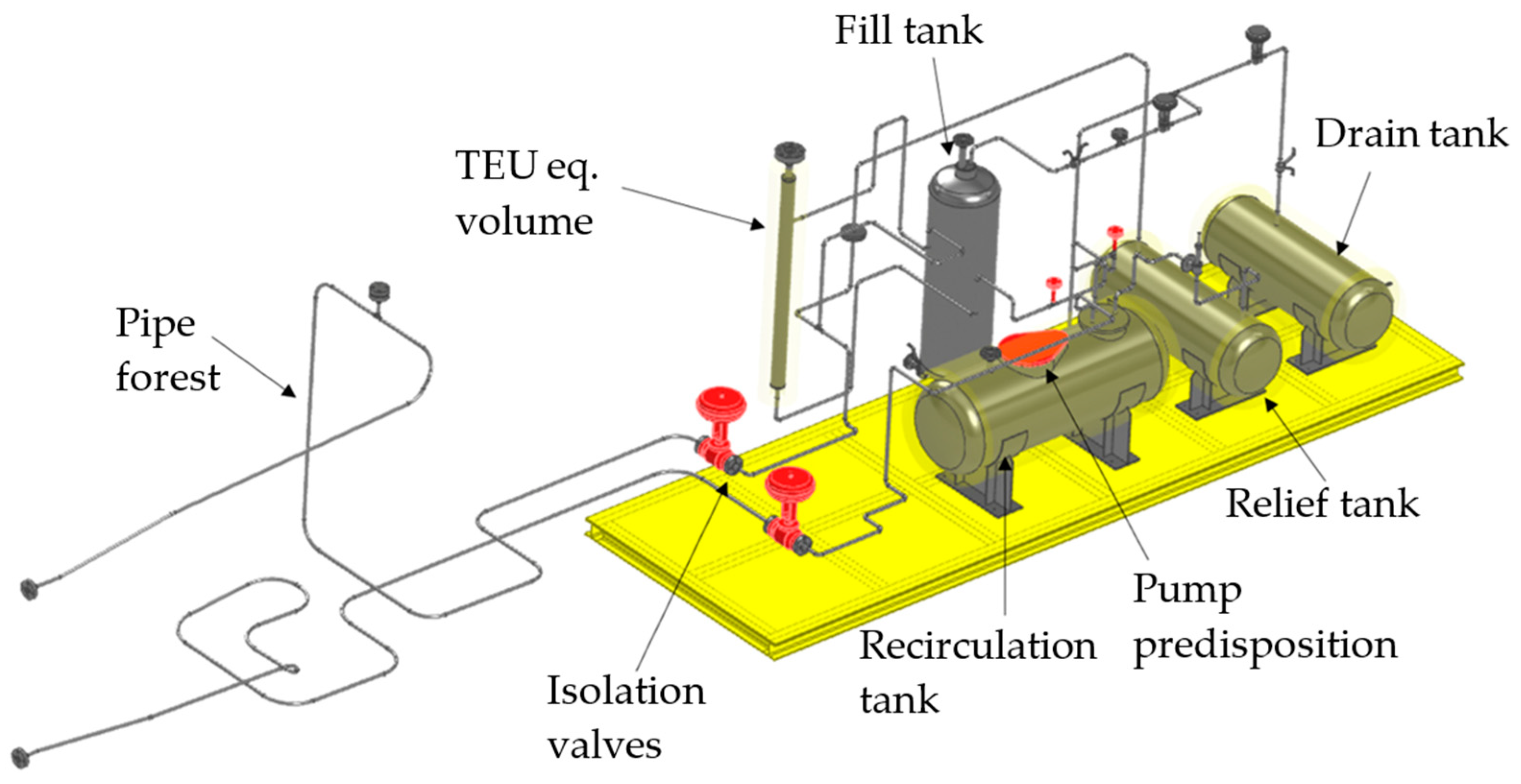
4.1. Integral Test Facility LIFUS5/Mod4 for the WCLL in-Box LOCA Experiments
- Generating data applicable to full-scale WCLL test blanket system (TBS) conditions that may be directly used for safety analysis;
- Providing integral test facility data for the understanding and study of the transient progression of a “in-box Loss Of Coolant Accident” in the WCLL BB of DEMO reactor;
- Supporting the development and demonstrating the reliability (i.e., validation and qualification) of computer codes, coupling techniques, and procedures for code use, when applied to simulating the behavior of a “in-box Loss Of Coolant Accident” at a system level.
4.2. Code Set-Up for Deterministic Safety Analysis of WCLL in-Box LOCA
4.2.1. RELAP5/Mod3.3 Code Development
- The inclusion of new coolant fluids, such as PbLi, lead–bismuth eutectic (LBE), HITEC©, and Pb;
- The adoption of new correlations to reproduce fluid–wall heat transfer phenomena with complex geometries and/or with liquid metal and molten salt coolants. The heat transfer phenomenon in liquid metals is dominated by thermal diffusivity due to their low Prandtl number (1). Correlations developed for water do not consider this aspect, thus making them unsuitable for use with liquid metals;
- The introduction of ad hoc correlations to consider magnetohydrodynamic (MHD) effects on system transport coefficients, i.e., pressure drops due to electromagnetic drag and modified heat transfer coefficients.
- Correlations for circular tubes or plates:
- Seban—Shimazaki;
- Cheng—Tak.
- Correlations for bundles:
- c.
- Sherbakov (shell side in helicoidal geometry only);
- d.
- Ushakov (rod bundle only);
- e.
- Mikityuk (rod bundle only);
- f.
- Kazimi—Carelli;
- g.
- Graber—Rieger (modified by Sha and Launder).
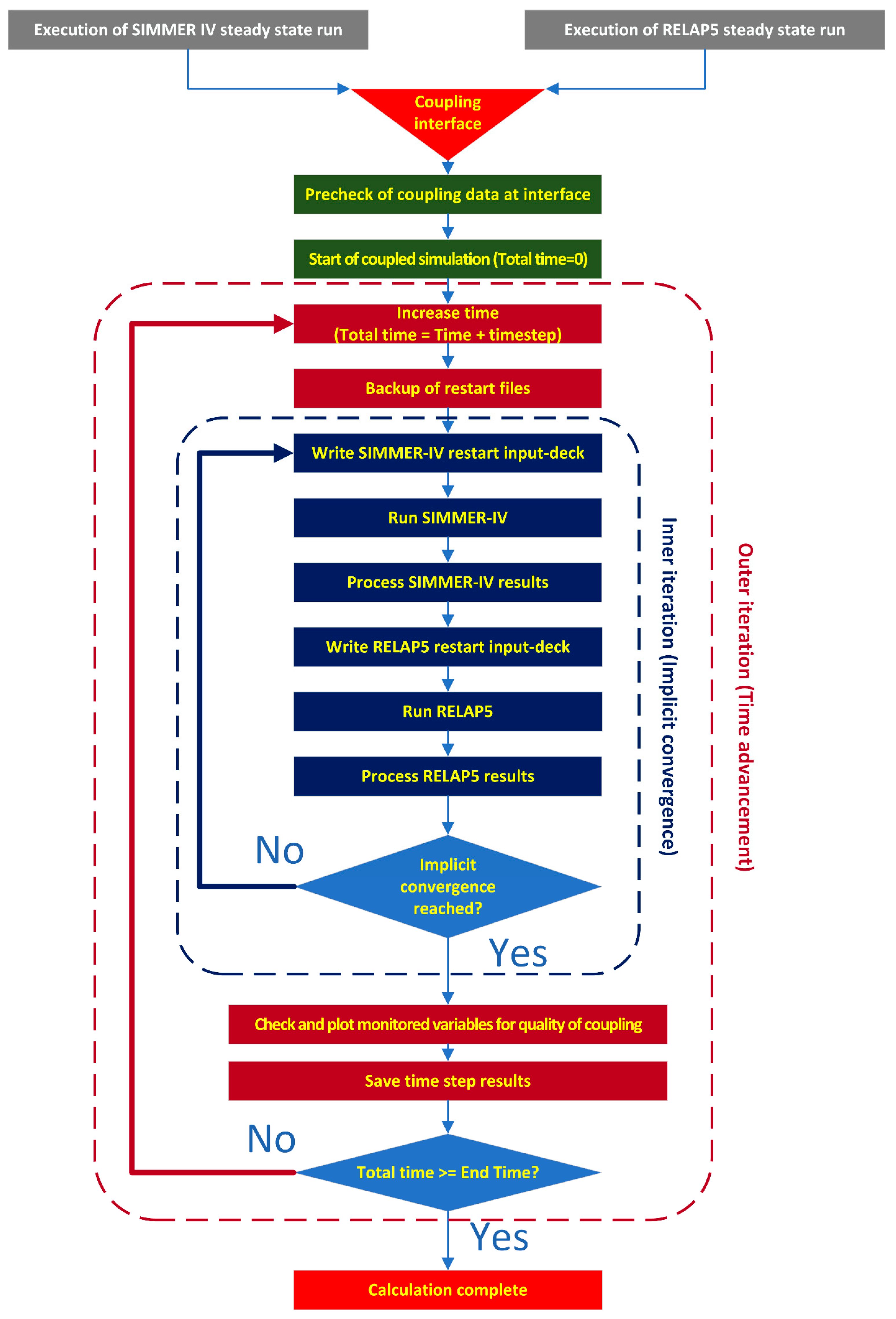
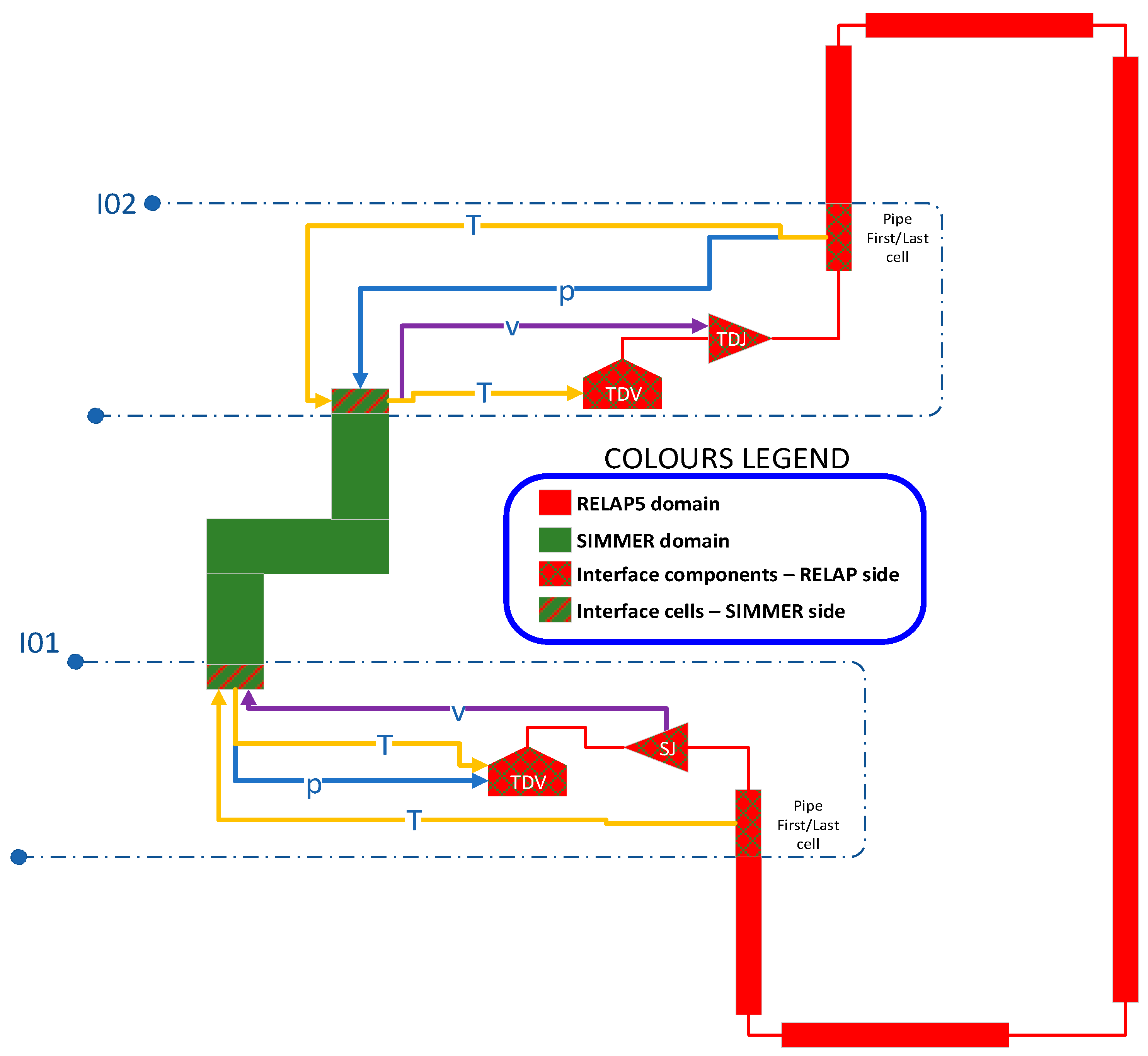
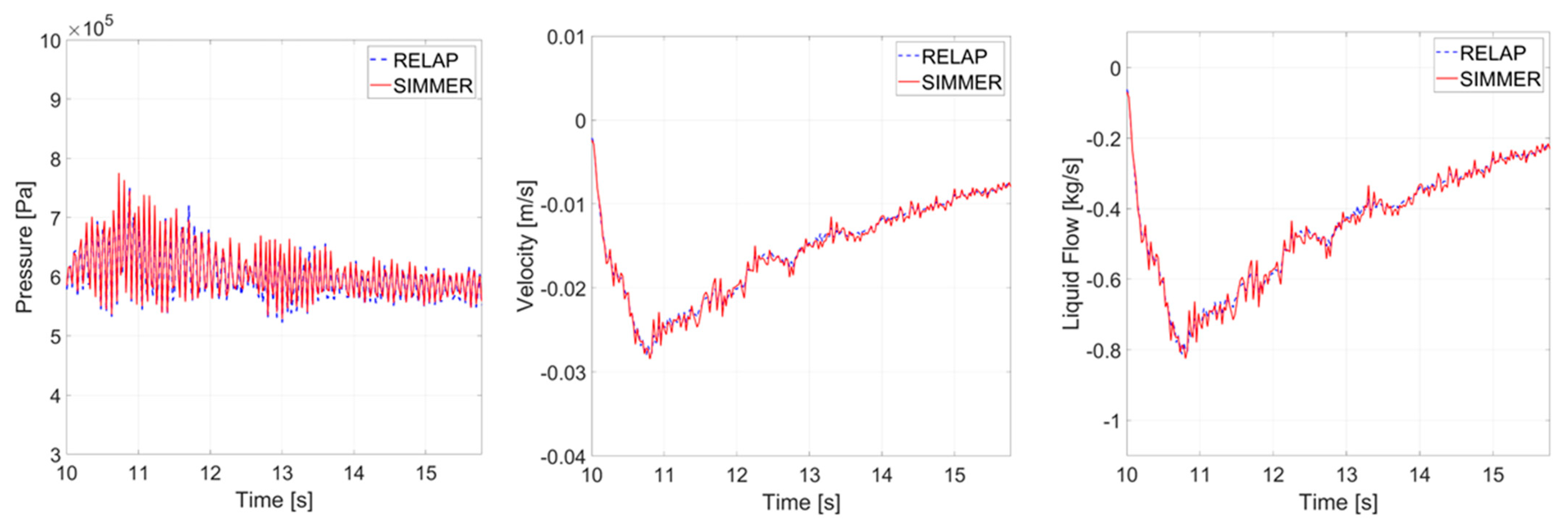
4.2.2. RELAP5/Mod3.3 and SIMMER Code Coupling
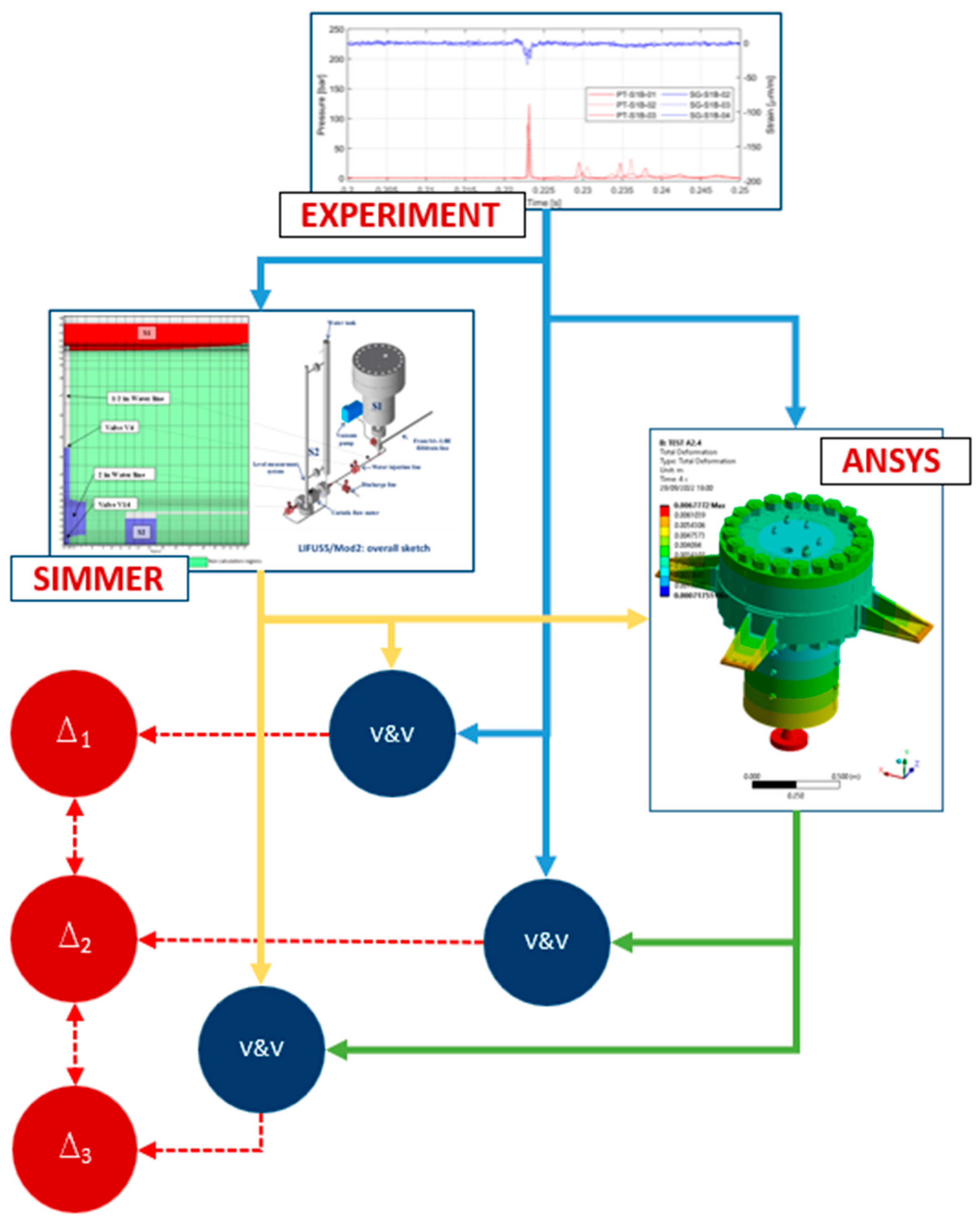
4.2.3. SIMMER–ANSYS Code Coupling
5. Conclusions
Author Contributions
Funding
Data Availability Statement
Conflicts of Interest
Nomenclature
| BB | Breeding Blanket |
| BC | Boundary Condition |
| BIC | Boundary and Initial Condition |
| CAD | Computer-Aided Design |
| CEA | Commissariat Energie Atomique |
| CFD | Computational Fluid Dynamics |
| DEMO | DEMOnstration Power Plant |
| DIAEE | Dipartimento di Ingegneria Astronautica, Elettrica ed Energetica |
| DICI | Dipartimento di Ingengeria Civile e Industriale |
| DSA | Deterministic Safety Analysis |
| ENEA | Italian National Agency for New Technologies, Energy and Sustainable Economic Development |
| EU | European |
| FCI | Fuel–Coolant Interaction |
| FP | Framework Programme |
| HTC | Heat Transfer Coefficient |
| ITER | International Thermonuclear Experimental Reactor |
| JRC | Joint Research Centre |
| LBE | Lead–Bismuth Eutectic |
| LMFR | Liquid Metal Fast Reactor |
| LOCA | Loss Of Coolant Accident |
| LWR | Light Water Reactor |
| MHD | Magnetohydrodynamic |
| P&ID | Piping and Instrumentation Diagram |
| PbLi | Lithium–Lead |
| PFD | Process Flow Diagram |
| PHTS | Primary Heat Transfer System |
| R&D | Research and Development |
| RC | Research Center |
| SYS-TH | SYStem-ThermoHydraulic |
| TBM | Test Blanket Module |
| TBS | Test Blanket System |
| TC | ThermoCouple |
| TEU | Trititum Extraction Unit |
| UNIPI | University of Pisa |
| US | United States |
| V&V | Verification and Validation |
| WCLL | Water-Cooled Lithium–Lead |
| WPBB | Work Package Breeding Blanket |
References
- Cismondi, F.; Spagnuolo, G.A.; Boccaccini, L.V.; Chiovaro, P.; Ciattaglia, S.; Cristescu, I.; Day, C.; Del Nevo, A.; Di Maio, P.A.; Federici, G.; et al. Progress of the conceptual design of the European DEMO breeding blanket, tritium extraction and coolant purification systems. Fusion Eng. Des. 2020, 157, 111640. [Google Scholar] [CrossRef]
- Aubert, J.; Aiello, G.; Alonso, D.; Batal, T.; Boullon, R.; Burles, S.; Cantone, B.; Cismondi, F.; Del Nevo, A.; Maqueda, L.; et al. Design and preliminary analyses of the new Water Cooled Lithium Lead TBM for ITER. Fusion Eng. Des. 2020, 160, 111921. [Google Scholar] [CrossRef]
- Arena, P.; Del Nevo, A.; Moro, F.; Noce, S.; Mozzillo, R.; Imbriani, V.; Giannetti, F.; Edemetti, F.; Froio, A.; Savoldi, L.; et al. The DEMO Water-Cooled Lead–Lithium Breeding Blanket: Design Status at the End of the Pre-Conceptual Design Phase. Appl. Sci. 2021, 11, 11592. [Google Scholar] [CrossRef]
- Ciurluini, C.; Giannetti, F.; Tincani, A.; Del Nevo, A.; Caruso, G.; Ricapito, I.; Cismondi, F. Thermal-hydraulic modeling and analysis of the Water Cooling System for the ITER Test Blanket Module. Fusion Eng. Des. 2020, 158, 111709. [Google Scholar] [CrossRef]
- Ciurluini, C.; Narcisi, V.; Tincani, A.; Ortiz Ferrer, C.; Giannetti, F. Conceptual design overview of the ITER WCLL Water Cooling System and supporting thermal-hydraulic analysis. Fusion Eng. Des. 2021, 171, 112598. [Google Scholar] [CrossRef]
- Boccaccini, L.V.; Arbeiter, F.; Arena, P.; Aubert, J.; Bühler, L.; Cristescu, I.; Del Nevo, A.; Eboli, M.; Forest, L.; Harrington, C.; et al. Status of Maturation of Critical Technologies and Systems Design: Breeding Blanket. Fusion Eng. Des. 2022, 179, 113116. [Google Scholar] [CrossRef]
- Eboli, M.; Forgione, N.; Del Nevo, A. Implementation of the chemical PbLi/water reaction in the SIMMER code. Fusion Eng. Des. 2016, 109–111, 468–473. [Google Scholar] [CrossRef]
- Eboli, M.; Forgione, N.; Del Nevo, A. Assessment of SIMMER-III code in predicting Water Cooled Lithium Lead Breeding Blanket “in-box-Loss Of Coolant Accident”. Fusion Eng. Des. 2021, 163, 112127. [Google Scholar] [CrossRef]
- Eboli, M.; Khani Moghanaki, S.; Martelli, D.; Forgione, N.; Porfiri, M.T.; Del Nevo, A. Experimental activities for in-box LOCA of WCLL BB in LIFUS5/Mod3 facility. Fusion Eng. Des. 2019, 146 Pt A, 914–919. [Google Scholar] [CrossRef]
- Eboli, M.; Galleni, F.; Forgione, N.; Badodi, N.; Cammi, A.; Del Nevo, A. Experimental and Numerical Results of LIFUS5/Mod3 Series E Test on In-box LOCA Transient for WCLL-BB. Energies 2021, 14, 8527. [Google Scholar] [CrossRef]
- Eboli, M.; Crugnola, R.M.; Cammi, A.; Khani, S.; Forgione, N.; Del Nevo, A. Test Series D experimental results for SIMMER code validation of WCLL BB in-box LOCA in LIFUS5/Mod3 facility. Fusion Eng. Des. 2020, 156, 111582. [Google Scholar] [CrossRef]
- Badodi, N.; Cammi, A.; Eboli, M.; Martelli, D.; Del Nevo, A. Experimental results of PbLi-water reaction performed in LIFUS5/Mod3 separate effect test facility. Nucl. Technol. 2023, 209, 1508–1522. [Google Scholar] [CrossRef]
- Prakash Saraswat, S.; Cossu, V.; Galleni, F.; Eboli, M.; Del Nevo, A.; Forgione, N. Progress towards the validation of SIMMER-III code model for lead lithium water chemical interaction. Fusion Eng. Des. 2023, 193, 113819. [Google Scholar] [CrossRef]
- Khani, S.; Galleni, F.; Eboli, M.; Del Nevo, A.; Paci, S.; Forgione, N. Post-test analysis of Series D experiments in LIFUS5/Mod3 facility for SIMMER code validation of WCLL-BB In-box LOCA. Fusion Eng. Des. 2021, 165, 112268. [Google Scholar] [CrossRef]
- Khani, S.; Galleni, F.; Eboli, M.; Del Nevo, A.; Paci, S.; Forgione, N. Analysis of Test D1.1 of the LIFUS5/Mod3 facility for In-box LOCA in WCLL-BB. Fusion Eng. Des. 2020, 160, 111832. [Google Scholar] [CrossRef]
- Khani Moghanaki, S.; Eboli, M.; Forgione, N.; Martelli, D.; Del Nevo, A. Validation of SIMMER-III code for in-box LOCA of WCLL BB: Pre-test numerical analysis of Test D1.1 in LIFUS5/Mod3 facility. Fusion Eng. Des. 2019, 146 Pt A, 978–982. [Google Scholar] [CrossRef]
- Galleni, F.; Cossu, V.; Pesetti, A.; Eboli, M.; Del Nevo, A.; Forgione, N. Development of a coupling technique between RELAP5 and SIMMER-IV for fusion reactor applications. Fusion Eng. Des. 2023, 193, 113682. [Google Scholar] [CrossRef]
- Cossu, V.; Galleni, F.; Eboli, M.; Del Nevo, A.; Forgione, N.; Paci, S. Lithium-Lead/water interaction: LIFUS5/Mod3 series E tests analysed by SIMMER-III coupled with RELAP5. Fusion Eng. Des. 2023, 190, 113537. [Google Scholar] [CrossRef]
- Galleni, F.; Khani Moghanaki, S.; Eboli, M.; Del Nevo, A.; Paci, S.; Ciolini, R.; Lo Frano, R.; Forgione, N. RELAP5/SIMMER-III code coupling development for PbLi-water interaction. Fusion Eng. Des. 2020, 153, 111504. [Google Scholar] [CrossRef]
- Gonfiotti, B.; Khani Moghanaki, S.; Eboli, M.; Barone, G.; Martelli, D.; Del Nevo, A. Development of a SIMMER\RELAP5 coupling tool. Fusion Eng. Des. 2019, 146 Pt B, 1993–1997. [Google Scholar] [CrossRef]
- Badodi, N.; Eboli, M.; Cammi, A.; Del Nevo, A. Development and validation of a SIMMER-III/ANSYS code chain methodology for the integral safety analysis of WCLL fusion reactor components. In Proceedings of the 2023 30th International Conference on Nuclear Engineering ICONE30-1857, Kyoto, Japan, 21–26 May 2023. [Google Scholar]
- Narcisi, V.; Melchiorri, L.; Giannetti, F. Improvements of RELAP5/Mod3.3 heat transfer capabilities for simulation of in-pool passive power removal systems. Ann. Nucl. Energy 2021, 160, 108436. [Google Scholar] [CrossRef]
- Melchiorri, L.; Narcisi, V.; Giannetti, F.; Caruso, G.; Tassone, A. Development of a RELAP5/MOD3.3 Module for MHD Pressure Drop Analysis in Liquid Metals Loops: Verification and Validation. Energies 2021, 14, 5538. [Google Scholar] [CrossRef]
- Badodi, N.; Eboli, M.; Cammi, A.; Del Nevo, A. Status, Features, and Future Development of the LIFUS5/Mod4 Experimental Facility Design. Appl. Sci. 2023, 13, 482. [Google Scholar] [CrossRef]
- Corradini, M.L.; Jeppson, D.W. Lithium alloy chemical reactivity with reactor materials: Current state of knowledge. Fusion Eng. Des. 1991, 14, 273–288. [Google Scholar] [CrossRef]
- Jeppson, D.W. Summary of Lithium-Lead Alloy Safety Compatibility Tests; WHC-EP-0202; Westinghouse Hanford Company: Richland, WA, USA, 1989. [Google Scholar]
- Jeppson, D.W.; Muhlestein, L.D. Safety considerations of lithium-lead alloy as a fusion reactor breeding material. Fusion Technol. 1985, 8, 1385–1391. [Google Scholar] [CrossRef]
- Herzog, J.P. Lithium-Lead/Water Interactions: Experiments and Analysis; UWFDM-791; University of Wisconsin: Madison, WI, USA, 1989. [Google Scholar]
- Kranert, O.; Kottowski, H. Small scale lithium-lead/water interaction studies. Fusion Eng. Des. 1991, 15, 137–154. [Google Scholar] [CrossRef]
- Savatteri, C.; Gemelli, A. Lithium-lead/water interaction. Large break experiments. Fusion Eng. Des. 1991, 17, 343–349. [Google Scholar] [CrossRef]
- Ciampichetti, A.; Ricapito, I.; Aiello, A.; Benamati, G. Water large leaks into liquid Pb-17Li: First experimental results on LIFUS 5 facility. Fusion Eng. Des. 2003, 69, 563–567. [Google Scholar] [CrossRef]
- Ciampichetti, A. Final report on TW2-TTBA-005-D1. Water large leaks into liquid Pb-16Li: Tests n. 6-7-8 on LIFUS5, LB-A-R-019. Technical Report, 15 September 2003. [Google Scholar]
- Ciampichetti, A.; Forgione, N.; Pesetti, A.; Angelo, I. DEMO safety study of the water—PbLi reaction. TA WP12-DAS-02-T03. EFDA Report, 31 December 2012. [Google Scholar]
- Sardain, P.; Benamati, G.; Ricapito, I.; Marbach, G. Modelling of the Pb17Li/water interaction within a blanket module. Fusion Eng. Des. 2000, 51–52, 611–616. [Google Scholar] [CrossRef]
- Sardain, P. Consequences of Pb-17Li/water Interaction within a Blanket Module, H0-5010-230-3012. CEA Draft Report, 1 July 1998. [Google Scholar]
- Del Nevo, A. Water-LiPb Reaction Study. TA WP13-SYS-04-T06. EFDA Report. Available online: https://idm.euro-fusion.org/default.aspx?uid=2APBVK (accessed on 17 March 2014).
- Ciampichetti, A.; Ricapito, I.; Forgione, N.; Pesetti, A. Pb-16Li/water interaction: Experimental results and preliminary modelling activities. Fusion Eng. Des. 2013, 88, 2392–2395. [Google Scholar] [CrossRef]
- Piet, S.J.; Jeppson, D.W.; Muhlestein, L.D.; Kazimi, M.S.; Corradini, M.L. Liquid metal chemical reaction safety in fusion facilities. Fusion Eng. Des. 1987, 5, 273–298. [Google Scholar] [CrossRef]
- Japan Nuclear Cycle Development Institute. SIMMER-III (Version 3.F) Input Manual; Ōarai Engineering Center, Japan Nuclear Cycle Development Institute: Ōarai, Japan, 2012.
- Japan Nuclear Cycle Development Institute. SIMMER-IV (Version 2.F) Input Manual; Ōarai Engineering Center, Japan Nuclear Cycle Development Institute: Ōarai, Japan, 2012.
- Tincani, A.; Arena, P.; Bruzzone, M.; Catanzaro, I.; Ciurluini, C.; Del Nevo, A.; Di Maio, P.A.; Forte, R.; Giannetti, F.; Lorenzi, S.; et al. Conceptual design of the main Ancillary Systems of the ITER Water Cooled Lithium Lead Test Blanket System. Fusion Eng. Des. 2021, 167, 112345. [Google Scholar] [CrossRef]
- Idaho National Engineering Laboratory (INEL). RELAP5/Mod3.3 Code Manual Volume I: Code Structure, System Modelds, and Solution Methods; Idaho National Engineering Laboratory (INEL): Idaho Falls, ID, USA, 2003. [Google Scholar]
- Melchiorri, L.; Narcisi, V.; Ciurluini, C.; Giannetti, F.; Caruso, G.; Tassone, A. Preliminary MHD pressure drop analysis for the prototypical WCLL TBM with RELAP5/MOD3.3. Fusion Eng. Des. 2022, 176, 113048. [Google Scholar] [CrossRef]
- Barone, G.; Martelli, D.; Forgione, N. Implementation of Lead-Lithium as working fluid in RELAP5/Mod3.3. Fusion Eng. Des. 2019, 146, 1308–1312. [Google Scholar] [CrossRef]
- Forgione, N.; Galleni, F.; Risi, C.; Saija, G.; Pesetti, A. Review and Final Implementation of Working Fluids in RELAP5/Mod3.3 Version: PbLi and Molten Salt, EFDA_D_2QJJ6A. Available online: https://idm.euro-fusion.org/default.aspx?uid=2QJJ6A (accessed on 22 February 2022).
- Kolev, N.I. Multiphase Flow Dynamics 4; Springer: Berlin/Heidelberg, Germany, 2012. [Google Scholar]
- Eboli, M.; Giannetti, F.; Ciurluini, C.; Gonfiotti, B.; Del Nevo, A. Report on HTC Correlations in Relevant WCLL-TBS Configuration, EFDA_D_2PR56G. Available online: https://idm.euro-fusion.org/default.aspx?uid=2PR56G (accessed on 22 March 2022).
- Müller, U.; Bühler, L. Magnetofluiddynamics in Channels and Containers; Springer-Verlag Berlin Heidelberg GmbH: Karlsruhe, Germany, 2001. [Google Scholar] [CrossRef]
- Smolentsev, S.; Moreau, R.; Bühler, L.; Mistrangelo, C. MHD thermofluid issues of liquid-metal blankets: Phenomena and advances. Fusion Eng. Des. 2010, 85, 1196–1205. [Google Scholar] [CrossRef]
- Melchiorri, L.; Siriano, S.; Tassone, A. RELAP5/Mod3.3 MHD module development and validation: WCLL TBM mock-up model. In Proceedings of the 15th ISFNT Conference, Las Palmas de Gran Canaria, Spain, 10–15 September 2023. [Google Scholar]
- Miyazaki, K.; Kotake, S.; Yamaoka, N.; Inoue, S.; Fujii-E, Y. MHD pressure drop of NaK flow in stainless steel pipe. Nucl. Technol. 1983, 4, 447–452. [Google Scholar] [CrossRef]
- Miyazaki, K.; Inoue, S.; Yamaoka, N.; Horiba, T.; Yokomizo, K. Magneto-Hydro-Dynamic Pressure Drop of Lithium Flow in Rectangular Ducts. Fusion Technol. 1986, 10, 830–836. [Google Scholar] [CrossRef]
- Kirillov, I.R.; Reed, C.B.; Barleon, L.; Miyazaki, K. Present understanding of MHD and heat transfer phenomena for liquid metal blankets. Fusion Eng. Des. 1995, 27, 553–569. [Google Scholar] [CrossRef]
- Bühler, L.; Horanyi, S. Experimental investigations of MHD flows in a sudden expansion. Wiss. Berichte FZKA 2006, 7245, 1–65. [Google Scholar]
- Feng, J.; He, Q.; Chen, H.; Ye, M. Numerical Investigation of magnetohydrodynamic flow through Sudden expansion pipes in Liquid Metal Blankets. Fusion Eng. Des. 2016, 109–111, 1360–1364. [Google Scholar] [CrossRef]
- Reimann, J.; Molokov, S.; Platnieks, I.; Platacis, E. Mhd-Flow in Multichannel U-Bends: Screening Experiments and Theoretical Analysis. In Proceedings of the 17th Symposium on Fusion Technology, Rome, Italy, 14–18 September 1992; pp. 1454–1458. [Google Scholar] [CrossRef]
- Bühler, L.; Mistrangelo, C.; Brinkmann, H.J. Experimental investigation of liquid metal MHD flow entering a flow channel insert. Fusion Eng. Des. 2020, 154, 111484. [Google Scholar] [CrossRef]
- Ciurluini, C.; Giannetti, F.; Martelli, E.; Del Nevo, A.; Barucca, L.; Caruso, G. Analysis of the thermal-hydraulic behavior of the EU-DEMO WCLL breeding blanket cooling systems during a loss of flow accident. Fusion Eng. Des. 2021, 164, 112206. [Google Scholar] [CrossRef]
- Ciurluini, C.; Giannetti, F.; Del Nevo, A.; Caruso, G. Study of the EU-DEMO WCLL breeding blanket primary cooling circuits thermal-hydraulic performances during transients belonging to LOFA category. Energies 2021, 14, 1541. [Google Scholar] [CrossRef]


| Test Series D | D Orifice(mm) | Water Injected (g) | Water T (°C) | PbLi T (°C) | Injection Pressure (bar) |
|---|---|---|---|---|---|
| 1.1 | 4 | 50 | 295 | 330 | 155 |
| 1.2 | 4 | 50 | 295 | 330 | 155 |
| 1.3 | 4 | 50 | 295 | 330 | 155 |
| 1.4 | 4 | 50 | 295 | 330 | 155 |
| 1.5 | 4 | 50 | 295 | 330 | 155 |
| 2.1 | 4 | 100 | 295 | 330 | 155 |
| 2.2 | 4 | 100 | 295 | 330 | 155 |
| 3.1 | 4 | 50 | 295 | 450 | 155 |
| 4.1 | 4 | 50 | 330 | 330 | 155 |
| 5.1 | 4 | 150 | 295 | 330 | 155 |
| Test Series E | D Orifice (mm) | Water T (°C) | PbLi T (°C) | Injection Time (s) | Injection Pressure (bar) |
|---|---|---|---|---|---|
| #1.1 | 4 | 295 | 330 | 1 | 155 |
| #2.1 | 4 | 295 | 430 | 1 | 155 |
| #3.1 | 1 | 295 | 330 | 0.5 | 155 |
| #4.1 | 2 | 295 | 330 | 1 | 155 |
| #5.1 | 1 | 295 | 330 | 1.5 | 155 |
| #6.1 | 4 | 295 | 380 | 1 | 155 |
| #7.1 | 2 | 295 | 380 | 1.3 | 155 |
| #8.1 | 1 | 295 | 380 | 2 | 155 |
| General Characteristics | |
| Facility type | Stagnant PbLi loop |
| Operating fluid | Eutectic PbLi alloy (Li 17%, Pb 83%) |
| Heat source and power | Heating wires and bands |
| Hydraulic Characteristics | |
| Fluid | Pb-83 Li-17 eutectic alloy |
| PbLi Inventory | 0.593 m3 |
| Operating temperature range | 350–450 °C |
| Operating pressure | 0.1 MPa |
| Design pressure | 18.5 MPa |
| Operating mass flow rate | 0 kg/s |
| Key instrumentation | Fast pressure transducers, strain gauges, hydrogen analysis system, thermocouples, and level meters. |
Disclaimer/Publisher’s Note: The statements, opinions and data contained in all publications are solely those of the individual author(s) and contributor(s) and not of MDPI and/or the editor(s). MDPI and/or the editor(s) disclaim responsibility for any injury to people or property resulting from any ideas, methods, instructions or products referred to in the content. |
© 2023 by the authors. Licensee MDPI, Basel, Switzerland. This article is an open access article distributed under the terms and conditions of the Creative Commons Attribution (CC BY) license (https://creativecommons.org/licenses/by/4.0/).
Share and Cite
Eboli, M.; Arena, P.; Badodi, N.; Cammi, A.; Ciurluini, C.; Cossu, V.; Forgione, N.; Galleni, F.; Giannetti, F.; Gonfiotti, B.; et al. PbLi/Water Reaction: Experimental Campaign and Modeling Advancements in WPBB EUROfusion Project. Energies 2023, 16, 7729. https://doi.org/10.3390/en16237729
Eboli M, Arena P, Badodi N, Cammi A, Ciurluini C, Cossu V, Forgione N, Galleni F, Giannetti F, Gonfiotti B, et al. PbLi/Water Reaction: Experimental Campaign and Modeling Advancements in WPBB EUROfusion Project. Energies. 2023; 16(23):7729. https://doi.org/10.3390/en16237729
Chicago/Turabian StyleEboli, Marica, Pietro Arena, Nicolò Badodi, Antonio Cammi, Cristiano Ciurluini, Vittorio Cossu, Nicola Forgione, Francesco Galleni, Fabio Giannetti, Bruno Gonfiotti, and et al. 2023. "PbLi/Water Reaction: Experimental Campaign and Modeling Advancements in WPBB EUROfusion Project" Energies 16, no. 23: 7729. https://doi.org/10.3390/en16237729
APA StyleEboli, M., Arena, P., Badodi, N., Cammi, A., Ciurluini, C., Cossu, V., Forgione, N., Galleni, F., Giannetti, F., Gonfiotti, B., Martelli, D., Melchiorri, L., Risi, C., Tassone, A., & Del Nevo, A. (2023). PbLi/Water Reaction: Experimental Campaign and Modeling Advancements in WPBB EUROfusion Project. Energies, 16(23), 7729. https://doi.org/10.3390/en16237729