Article

Preliminary Experimental Quantification of Helium Leakages from Flanged Connections at HCPB TBS Operative Conditions

1
ENEA Brasimone, Camugnano, 40032 Bologna, Italy
2
Nuclear Section, Department of Astronautical, Electrical and Energy Engineering, Sapienza University of Rome, Corso Vittorio Emanuele II 244, 00186 Rome, Italy
*
Author to whom correspondence should be addressed.
Energies 2023, 16(14), 5519; https://doi.org/10.3390/en16145519
Submission received: 3 January 2023 / Revised: 21 April 2023 / Accepted: 28 June 2023 / Published: 21 July 2023

Abstract

:
The HCPB TBS (Helium-Cooled Pebble Bed Test Blanket System) is one of the two European TBSs that will be installed and tested in the ITER reactor. The use of flanged connections in the Helium Coolant System and the Tritium Extraction System of the HCPB TBS would make the remote maintenance operations easier and faster. Therefore, investigating the helium leakage from flanges becomes a fundamental step toward the control of the tritium activity in the Port Cell, as the helium flow will contain a variable but not negligible amount of tritium. The first set of experiments on helium leakages from flanged connections is described in this paper. The experiments were performed in a HeFUS3 facility, an eight-shaped helium loop designed to work at HCPB-TBS-relevant conditions. The facility can provide a helium mass flow rate in the range of 0.27–1.4 kg/s and can reach a pressure as high as 80 bar and a temperature up to 530 °C. Two types of gaskets were tested in this campaign: a spiral-wound gasket and an oval ring joint. The gasket/flange assemblies are described in detail in this paper, together with the test section that hosts them and the performed commissioning tests. The tests were carried out at 500 °C and 80 bar. In these conditions, the leak rate from the flange with the oval ring joint resulted in being, on average, 1.42·10−6 mbar∙L/s, while the leak rate from the flange with the spiral-wound gasket resulted in being, on average, 3.73·10−3 mbar∙L/s.

1. Introduction

Following the expected high gamma irradiation, maintenance operations on the Test Blanket Systems (TBSs) of the ITER fusion reactor are required to be fully remote. The maintenance requirements for the European TBSs are described in detail in Galabert et al.’s study [1], which includes a description of inspections, predictive maintenance, and corrective maintenance procedures for the various subsystems.
In order to facilitate and shorten the Remote Maintenance (RM [2]) of the HCS (Helium Cooling System) components of the HCPB TBS (Helium Cooled Pebble Beds) [3], IO (ITER Organization) requested to design and manufacture the critically positioned components with flanged connections. For example, pipes of the Ancillary Equipment Unit (AEU) will need to be dismantled, and Remote Maintenance operations on flanged connections are much faster than on welded joints. Considering this preference for flanged connections expressed by the Remote Maintenance team, ITER Organization required a first estimation of the leakage rate from flanged connections. The results of this activity can be used as the basis to decide the type of connection and possible mitigation strategies. For instance, the use of guard pipes can help both in preventing tritium from contaminating the building and in detecting increases in the leak rate [4]. This could also prevent long and painful decontamination operations.
The importance of helium leakages on the total tritium release rate has been recognized since the early development of TBSs, together with the need to quantify them and prepare mitigation strategies (e.g., see the study by Wong et al. on helium cooling for fusion reactors in general [5] or Farabolini et al.’s analysis, which is more focused on helium-cooled TBSs [6]). Instead, the possibility of significant amounts of tritiated water to leak from seals and flanges was excluded by the analysis of Fütterer et al. [7].
Following the decision to reduce the equatorial ports available for TBM (Test Blanket Module) testing from three to two [8] and the current strategy of optimizing the testing of different coolant–breeder combinations, the HCPB TBS will likely not be directly included in the testing program. However, the results described in this paper are also relevant for other helium-cooled TBMs, such as the Korean-supported Helium-Cooled Ceramic Reflector [9], which has similar operative conditions and RM needs.

2. Materials and Methods

HeFUS3 (Figure 1) is an eight-shaped helium loop designed and built by ENEA that has working conditions that are relevant for the HCPB TBS. The facility can provide a helium mass flow rate in the range of 0.27–1.4 kg/s and can reach a pressure as high as 80 bar and a temperature up to 530 °C [10]. HeFUS3 has been used in the past to test instrumentation and to simulate accidental transient scenarios (LOCA and LOFA). Moreover, simulations with RELAP5-3D have been carried out with the aim of reproducing the experimental campaign in steady-state and transient conditions [11].
The eight-shaped configuration allows for the two separate loop regions to have different temperature regimes: the one containing the helium turbo-circulator, which tolerates a maximum temperature of 100 °C, and the region of the test section, where a maximum temperature of 530 °C can be reached. An economizer, which is placed in the middle between the two regions, allows for the recovery of enthalpy. Two coolers reduce the helium temperature to below 100 °C: a water-cooled heat exchanger is always under operation, while the air cooler is only switched on with the most challenging operative conditions. The main loop components in the present configuration are as follows:
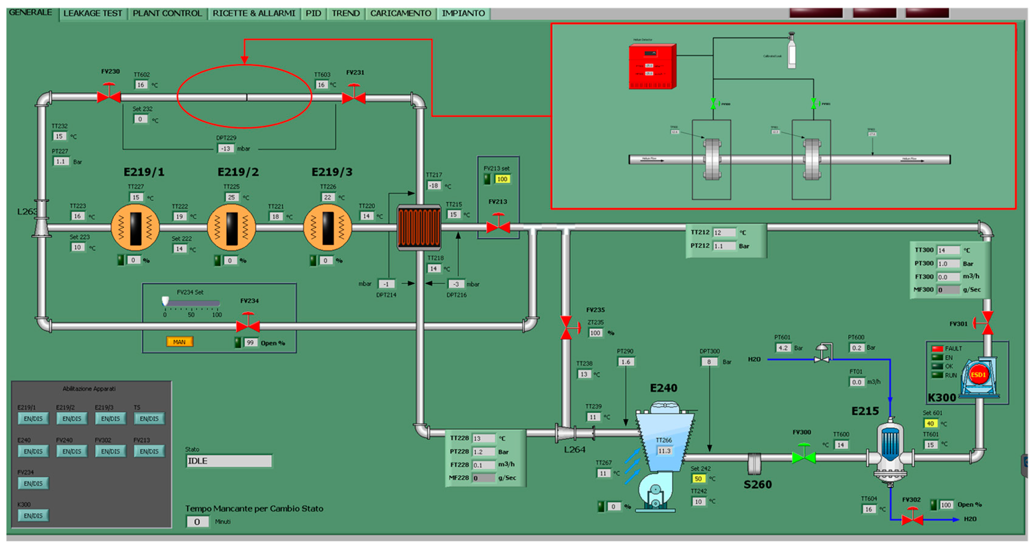
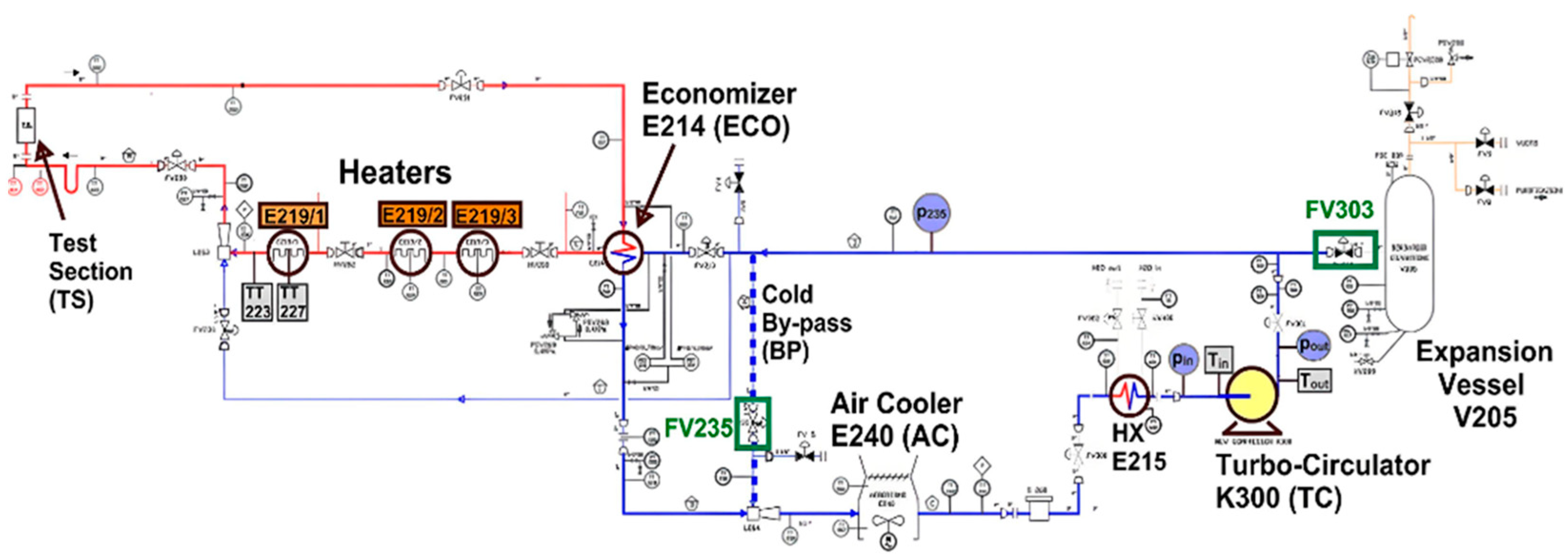
  • The compressor, which is able to deliver a maximum flow-rate of 1.4 kg/s;
  • Three electrical heaters, for a total power of 210 kW;
  • Two cooling systems: a shell-and-tube helium–water heat exchanger (1 MW) and an air cooler (about 300 kW);
  • A shell-and-tube helium–helium heat exchanger (economizer);
  • The electrical cabinet, which is able to supply 1.3 MW.
The compressor (K300) is a turbo-circulator designed as a one-stage centrifugal turbo machine driven by a built-in high-speed asynchronous motor. The turbo-circulator has a single-stage impeller with the electrical motor immersed in helium inside a pressure vessel closed at the two ends by dismountable flanges. The electric motor shaft is supported by magnetic bearings. The working stage of the TC consists of a blades wheel, a vane diffuser, and a spiral case. The wheel is fixed to the shaft of the high-speed asynchronous motor, which is supported by magnetic bearings.
The heater system is subdivided into three identical heating modules (E219-1/2/3 in Figure 1), and each of them is constituted by a bundle of 30 U-bent active rods immersed in a vertical cylindrical pressure vessel. The rod bundle is provided with diaphragm plates for heat-transfer improvement. Each heating module can be controlled separately.
The air-cooler component (E240) is located at the compressor inlet in order to reduce the corresponding helium temperature below the maximum design value (100 °C). It is a counter-flow helium–air heat exchanger, where the helium flows inside the tube bundle, whilst the air flows outside the external surface of the tubes. A helicoidal stainless-steel sheet is welded on the outside surface of the tube to increase the overall thermal conductance. The bundle arrangement is as compact as possible, with the finned tubes in a triangular array and welded to two cylindrical distributors. Meanwhile, the tube-and-shell helium/water heat exchanger (E215) is characterized by a nominal thermal duty of 900 kW. It is in the cold branch, downstream of the air cooler, that it further cools the helium flowing towards the TC suction line. The primary fluid, helium, flows towards the tubes, and the water flows towards the shell zone with a series of diaphragm sheets.
The economizer (E214, Figure 2) is a high-efficiency (>79%) vertical shell-and-tube configuration helium/helium heat exchanger. It is placed at the crossover point to recover the gas enthalpy before recirculating the helium through the compressor. The hot helium coming from the Test Section flows through a bundle of straight tubes that are welded between two tube plates and immersed in a cylindrical pressure vessel. The cold helium counter-flows in the shell zone, where a series of diaphragm sheets allow the enhancement of the global thermal exchange.
The loop was designed to operate at the following operative modes:
  • Long-term isothermal cooling flow;
  • Slow thermal cycling flow;
  • Fast cold thermal shock flow;
  • LOCA/LOFA simulation.
The helium tank V205, located on the compressor outlet, with a capacity three times the overall volume of the piping (around 3 m3), has the main function to control the pressure variations due to the temperature excursion during the experimental test activity. The loop can be managed by the Data Acquisition and Control System for each functioning mode. An independent system is used for the control and monitoring of the turbo-circulator.
Pictures of the test section are shown in Figure 3. Each flanged connection is isolated from the environment and from the other flanged connections by a box welded around it. Each box is just slightly bigger than the flanged connection it encircles. Two Swagelok fittings are welded to each box: one to insert a K-type thermocouple in the box (in contact with the external surface of the flange) and the other to connect a pipeline to the box. A schematic of the test section is shown in Figure 4. The pipeline connects the boxes to the leak detector and to a calibrated leak (2.9·10−9 mbar∙L/s). An actuated Swagelok diaphragm valve can isolate each box from the rest of the line.
The selected leak detector Is the ASM 340, supplied by Pfeiffer Vacuum (Asslar, Germany), which can detect a minimum leak of 5·10−12 mbar∙L/s in vacuum mode. The leak detector is equipped with a vacuum station that pumps the vacuum in the boxes around the flanges under testing and a mass spectrometer that can measure hydrogen, helium-3, and helium-4 and that, in this experimental campaign, performed an integral measurement of the leaking helium in mbar∙L/s, from which it is possible to evaluate the average leak rate.
The calibrated leak was conceived to check If the leak detector was correctly measuring the leak, when the valves were closed (boxes isolated from the detector) and when the valves were open, but the facility was not filled with helium. This step was useful to assess the tightness of the whole test section and to exclude possible leaks from the external environment.
The experiments are relevant for the Helium Coolant System of the HCPB TBS and for the high-pressure leg of the Coolant Purification System (CPS), and they were carried out at the most challenging conditions (about 500 °C and 80 bar) [12]. Moreover, the results of the testing can be later extrapolated to the less challenging conditions of the Tritium Extraction System (TES).
Each test is started by opening one of the diaphragm valves after the testing conditions are reached. A vacuum in the corresponding box is created by the leak detector through its turbomolecular pump. After a stationary condition is reached, the acquisition of the measured leak is started. The test duration was adapted case by case, always trying to minimize the impact of random oscillations on the results. In the tests in which the signal was very stable, the test duration was shortened.
The tested flanges are compliant with the standard ANSI B16.5. The flanges, supplied by Stylflange S.r.l. (Ravenna, Italy), have a nominal diameter of 3 inches. Two types of gaskets were tested in this campaign: an oval ring joint in AISI 316 and a spiral-wound gasket with the metal part made of AISI 316L and mica-graphite as filler material. Both gaskets, shown in Figure 5, were manufactured by Tecnoservice Italia S.r.l. (Brescia, Italy), and they are compliant with ANSI B16.20. The flanges for the spiral-wound gasket have trapezoidal grooves, whose dimensions are shown in Table 1, while the dimensions and engineering tolerances of the oval ring joint are shown in Table 2.
Raised face flanges with concentric grooves were used with the spiral-wound gasket. Their dimensions are provided in Table 3. Table 4 shows the dimensions and engineering tolerances of the spiral-wound gasket. The spiral-wound gasket has the centering outer ring but not the inner ring.
Nine tests were performed: five on the oval ring joint and four on the spiral-wound gasket. Several other tests were rejected because of the unstable conditions or data-acquisition issues. Table 5 shows the conditions during the 9 tests.
Before we started the experiments, four commissioning phases were carried out. Firstly, the flanges with the spiral-wound gasket were tightened at 170 Nm, while the ones with the oval ring were tightened at 200 Nm. The tightening torques were suggested by the manufacturers. The tightness was later verified with a hydrostatic test at 160.7 bar and 20 °C with water for 4 h.
Secondly, the tightness of the test rig was assessed by using a leak detector in sniffing mode. A vacuum was created in the boxes, and then a small overpressure of helium was injected (using an external helium tank). Each welding and each fitting was sniffed with the detector to assess its tightness. This phase was preceded by X-ray radiographies on each welding joint that demonstrated the absence of porosities.
Thirdly, after the installation in HeFUS3, the vacuum was pumped for about 24 h in the entire facility to remove any trace of water and air. Then, the facility was heated up to 150 °C and kept at this temperature for about 24 h in order to degas the walls of the pipes and of the flanges. After 24 h, the vacuum was pumped again until the pressure reached an almost constant value at about 10 mbar. At this time, helium was flowing, and the pressure was about 20 bar. Then, a leak was simulated through a calibrated device to check the accuracy of the measurement. The outcome of this step was that the accuracy of the measurement was not significantly altered by the experimental setup.
Finally, a test in cold conditions, at about 40 bar, was carried out to check if the facility and the instrumentation were correctly working and to evaluate the flanges’ leak rate before heating up.

3. Results

The results of the tests are reported in this section. All of the tests were performed at about 80 bar and 500 °C, with flowing helium.
The leak rate of the oval ring joint resulted, on average, in being 1.42·10−6 mbar∙L/s, as shown in Figure 6. This average comes from the tests number two, three, four, and five, as the first test showed, on average, a leak rate of 1.54·10−5 mbar∙L/s, that is, one order of magnitude more than the other four. A deep investigation of the test parameters and of their trends during the first test revealed that the helium temperature underwent an abrupt excursion due to an unexpected transient in one of the three heaters. However, given that the test was repeated another 4 times, obtaining four very similar values among them, the first test was not considered in the average. The average standard deviation of the four tests is about 15%.
Instead, the leak rate of the spiral-wound gasket resulted in being, on average, 3.73∙10−3 mbar∙L/s, as shown in Figure 7. The average standard deviation is about 0.7%. As the leak rate of this gasket was considered with respect to expected values, the test section was disassembled at the end of the tests, and the bolts were checked to guarantee that they were not partially loosened during the heating and cooling processes. However, the bolts were still tightened with the same torque applied before the start of the experimental campaign (170 Nm), allowing us to exclude the theory that the leak rate values depend on the wrong installation of the gasket.
The time-dependent values depicted in the plots of Figure 6 and Figure 7 were averaged over the acquisition times to give an estimation of the leak rate. These average values are complemented by the standard deviation of the acquired data and by the estimation of the measuring error, which takes into account the accuracy of the instruments involved in the measurements, the errors introduced by the signal chain from the instruments to the data acquisition system, and the random oscillations of the measured quantities (by the so-called sum-root-squared method). The measuring errors evaluated in this way average to about ±20% for the oval ring joint measurements and to about ±5% for the spiral-wound gasket ones.

4. Discussion and Conclusions

An estimation of the leakage rate from flanged connections was requested by the ITER Organization, given the importance of flanged connections in the remote maintenance operations foreseen for the HCPB TBS. For this reason, leak rates were measured on two types of gaskets: oval ring joint (AISI 316L) and spiral-wound gasket (AISI 316L + mica-graphite). The test section was commissioned prior to the testing in order to verify the correct installation and to assess its capability to measure small leak rates. The tests were performed at about 500 °C and 80 bar, the most challenging conditions for flanged connections among the HCPB operating points.
The tests revealed a leak rate for the oval ring joint of about 1.42·10−6 mbar∙L/s, while the average value for the spiral-wound gasket was about 3.73·10−3 mbar∙L/s. The latter value is higher than expected and was originally associated with a possible issue with the flange tightening, maybe occurred during the heating of the facility. However, the test section was disassembled at the end of the tests, and the tightening was checked; the bolts were not loosened. It is the authors’ opinion that a further investigation could be worth performing to gain more insight into the use of spiral-wound gaskets in helium systems, for instance, by changing the flange design or the materials of the gasket itself.

Author Contributions

Conceptualization, M.U. and A.V.; methodology, A.V.; formal analysis, A.V. and F.P.; investigation, A.V. and F.P.; resources, M.U.; data curation, A.V. and F.P.; writing—original draft preparation, A.V.; writing—review and editing, A.V. and F.P.; visualization, F.P.; supervision, M.U.; project administration, M.U.; funding acquisition, M.U. All authors have read and agreed to the published version of the manuscript.

Funding

This work received funding from the Euratom Research and Training Programme 2014–2018 and 2019–2020, under grant agreement No. 633053.

Data Availability Statement

The data presented in this study are available on request from the corresponding author.

Acknowledgments

This work was carried out within the framework of the EUROfusion Consortium and received funding from the Euratom Research and Training Programme 2014–2018 and 2019–2020, under grant agreement No. 633053. The views and opinions expressed herein do not necessarily reflect those of the European Commission. The work of A. Venturini is financially supported by a EUROfusion Engineering Grant. The authors are grateful to Gianotti, Laffi, Sermenghi, and Valdiserri for their precious help before and during the experimental campaign.

Conflicts of Interest

The authors declare no conflict of interest.

References

  1. Galabert, J.; Hopper, D.; Neviere, J.-C.; Nodwell, D.; Pascal, R.; Poitevin, Y.; Ricapito, I.; White, G. Nuclear maintenance strategy and first steps for preliminary maintenance plan of the EU HCLL & HCPB Test Blanket Systems. Fus. Eng. Des. 2017, 116, 34–39. [Google Scholar]
  2. Damiani, C.; Palmer, J.; Takeda, N.; Annino, C.; Balagué, S.; Bates, P.; Bernal, S.; Cornellá, J.; Dubus, G.; Esqué, S.; et al. Overview of the ITER remote maintenance design and of the development activities in Europe. Fus. Eng. Des. 2018, 136, 1117–1124. [Google Scholar] [CrossRef]
  3. Ricapito; Calderoni, P.; Aiello, A.; Ghidersa, B.; Poitevin, Y.; Pacheco, J. Current design of the European TBM systems and implications on DEMO breeding blanket. Fus. Eng. Des. 2016, 109–111, 1326–1330. [Google Scholar] [CrossRef]
  4. Giancarli, L.M.; Bravo, X.; Cho, S.; Ferrari, M.; Hayashi, T.; Kim, B.-Y.; Leal-Pereira, A.; Martins, J.-P.; Merola, M.; Pascal, R.; et al. Overview of recent ITER TBM Program activities. Fus. Eng. Des. 2020, 158, 111674. [Google Scholar] [CrossRef]
  5. Wong, C.; Baxi, C.; Bourque, R.; Dahms, C.; Inamati, S.; Ryder, R.; Sager, G.; Schleicher, R. Helium cooling of fusion reactors. Fus. Eng. Des. 1994, 25, 249–262. [Google Scholar] [CrossRef]
  6. Farabolini, W.; Ciampichetti, A.; Dabbene, F.; Fütterer, M.; Giancarli, L.; Laffont, G.; Puma, A.L.; Raboin, S.; Poitevin, Y.; Ricapito, I.; et al. Tritium control modelling for a helium cooled lithium–lead blanket of a fusion power reactor. Fus. Eng. Des. 2006, 81, 753–762. [Google Scholar] [CrossRef]
  7. Fütterer, M.A.; Raepsaet, X.; Proust, E. Tritium permeation through helium-heated steam generators of ceramic breeder blankets for DEMO. Fus. Eng. Des. 1995, 29, 225–232. [Google Scholar] [CrossRef]
  8. Hernández, F.A.; Pereslavtsev, P.; Zhou, G.; Kang, Q.; D’amico, S.; Neuberger, H.; Boccaccini, L.V.; Kiss, B.; Nádasi, G.; Maqueda, L.; et al. Consolidated design of the HCPB Breeding Blanket for the pre-Conceptual Design Phase of the EU DEMO and harmonization with the ITER HCPB TBM program. Fus. Eng. Des. 2020, 157, 111614. [Google Scholar] [CrossRef]
  9. Cho, S.; Ahn, M.-Y.; Chun, Y.-B.; Gwon, H.; Jin, H.G.; Kim, B.S.; Kim, C.-S.; Kim, J.-I.; Kim, S.-K.; Ku, D.Y.; et al. Status of HCCR TBM program for DEMO blanket. Fus. Eng. Des. 2021, 171, 112553. [Google Scholar] [CrossRef]
  10. Barone, G.; Martelli, D.; Forgione, N.; Utili, M.; Ricapito, I. Experimental campaign on the upgraded He-FUS3 facility. Fus. Eng. Des. 2017, 123, 181–185. [Google Scholar] [CrossRef]
  11. Barone, G.; Coscarelli, E.; Forgione, N.; Martelli, D.; Del Nevo, A.; Tarantino, M.; Utili, M.; Ricapito, I.; Calderoni, P. Development of a model for the thermal-hydraulic characterization of the He-FUS3 loop. Fus. Eng. Des. 2015, 96–97, 212–216. [Google Scholar] [CrossRef]
  12. Tincani, A.; Aiello, A.; Ferrucci, B.; Granieri, M.; Voukelatou, K.; Ricapito, I.; Galabert, J.; Ortiz, C.; Arena, P.; Di Maio, P.A.; et al. Conceptual design of the enhanced coolant purification systems for the European HCLL and HCPB test blanket modules. Fus. Eng. Des. 2019, 146, 365–368. [Google Scholar] [CrossRef]
Figure 1. Main window of the Data Acquisition and Control System of HeFUS3 facility, with details of the test section.
Energies 16 05519 g001
Figure 2. P&ID of Hefus3 facility, with labels indicating the main components.
Energies 16 05519 g002
Figure 3. Pictures of the test section. The picture on the left shows, in the foreground, the leak detector used to measure the leak rates, while the test section can be seen in the background: the two cylinders host the flanged connections to be tested and are connected to the leak detector by two ¼″ stainless-steel pipes. The picture on the right shows the test section from the top, after thermal insulation was added to keep the temperature as constant as possible during the measurements. The ¼″ pipes can be seen in the top part of the picture, coming out from the thermal insulation.
Energies 16 05519 g003
Figure 4. Schematic of the test section assembly.
Energies 16 05519 g004
Figure 5. Schematics of the gaskets under testing. The picture on the left shows the spiral-wound gasket, with labels indicating the two parts that form it. The picture on the right shows the oval ring joint gasket, with a sketch of its peculiar cross-section.
Energies 16 05519 g005
Figure 6. Trends of the leak rate from the oval ring joint during the tests, from #1 (on the left of the top row) to #5 (on the bottom row).
Energies 16 05519 g006aEnergies 16 05519 g006b
Figure 7. Trends of the leak rate from the spiral-wound gasket during the tests, from #6 (on the left of the top row) to #9 (on the right of the bottom row).
Energies 16 05519 g007
Table 1. Dimensions of the flanges for the spiral-wound gasket.
ParameterValue
Roughness8.0 μm
Angle of the inclined side22.5°
Depth7.9 mm
Width11.9 mm
Pitch diameter123.8 mm
Table 2. Dimensions of the oval ring joint, with engineering tolerances.
ParameterValueTolerance
Width of the ring11.13 mm±0.50 mm
Height of the ring17.53 mm±0.50 mm
Mean diameter123.83 mm±0.18 mm
Table 3. Dimensions of the grooves of the flanges for the oval ring joint.
ParameterValue
Roughness250 μm
Height of a groove0.4 mm
Width of a groove0.8 mm
Number of grooves per inch50
Table 4. Dimensions of the spiral-wound gasket, with engineering tolerances.
ParameterValueTolerance
External diameter149.35 mm±0.8 mm
Width of the winding19.05 mm±0.8 mm
Internal diameter101.60 mm±0.4 mm
Thickness (winding)4.445 mm±0.127 mm
Thickness (ring)3.20 mm±0.105 mm
Table 5. Testing conditions for the 9 experiments performed during the experimental campaign.
Test NumberP
(bar)
Gasket
T (°C)
He T
(°C)
He Flow Rate
(g/s)
Tested Gasket
178.0472494362oval ring joint
280.0461490362oval ring joint
379.7460485362oval ring joint
479.6458483361oval ring joint
579.6456483361oval ring joint
680.0482491360spiral wound
780.0482492360spiral wound
880.0482492360spiral wound
979.6484493360spiral wound
Disclaimer/Publisher’s Note: The statements, opinions and data contained in all publications are solely those of the individual author(s) and contributor(s) and not of MDPI and/or the editor(s). MDPI and/or the editor(s) disclaim responsibility for any injury to people or property resulting from any ideas, methods, instructions or products referred to in the content.

