Article

The Design of Water Loop Facility for Supporting the WCLL Breeding Blanket Technology and Safety

1
Department of Astronautical, Electrical and Energy Engineering (DIAEE), Sapienza University of Rome, 00186 Rome, Italy
2
Department of Fusion and Nuclear Safety Technology, ENEA, 40032 Camugnano, Italy
3
Department of Fusion and Nuclear Safety Technology, ENEA, 00044 Rome, Italy
4
Nuclear Engineering Division, Department of Energy, Politecnico di Milano, 20156 Milan, Italy
5
Department of Civil and Industrial Engineering (DICI), University of Pisa, 56122 Pisa, Italy
6
Department of Engineering, University of Palermo, 90128 Palermo, Italy
*
Author to whom correspondence should be addressed.
Energies 2023, 16(23), 7746; https://doi.org/10.3390/en16237746
Submission received: 4 October 2023 / Revised: 16 November 2023 / Accepted: 21 November 2023 / Published: 24 November 2023

Abstract

:
The WCLL Breeding Blanket of DEMO and the Test Blanket Module (TBM) of ITER require accurate R&D activities, i.e., concept validation at a relevant scale and safety demonstrations. In view of this, the strategic objective of the Water Loop (WL) facility, belonging to the W-HYDRA experimental platform planned at C.R. Brasimone of ENEA, is twofold: to conduct R&D activities for the WCLL BB to validate design performances and to increase the technical maturity level for selection and validation phases, as well as to support the ITER WCLL Test Blanket System program. Basically, the Water Loop facility will have the capability to investigate the design features and performances of scaled-down or portions of breeding blanket components, as well as full-scale TBM mock-ups. It is a large-/medium-scale water coolant plant that will provide water coolant at high pressure and temperature. It is composed by single-phase primary (designed at 18.5 MPa and 350 °C) and secondary (designed at 2.5 MPa and 220 °C) systems thermally connected with a two-phase tertiary loop acting as an ultimate heat sink (designed at 6 bar and 80 °C). The primary loop has two main sources of power: an electrical heater up to about 1 MWe, installed in the cold side, downstream of the pump and upstream of the test section, and an electron beam gun acting as a heat flux generator. The WL has unique features and is designed as a multi-purpose facility capable of being coupled with the LIFUS5/Mod4 facility to study PbLi/water reaction at a large scale. This paper presents the status of the Water Loop facility, highlighting objectives, design features, and the analyses performed.

1. Introduction

The International Thermonuclear Experimental Reactor (ITER) project [1] stands as an ambitious international project supported over decades by R&D activities in the field of nuclear fusion technology. Located in Cadarache, France, it is a magnetic confinement tokamak of unprecedented scale and complexity that aims at achieving sustained nuclear fusion and demonstrating the scientific feasibility of controlled fusion reactions. The engineering required for ITER is exceptionally challenging; reactor components must withstand the extreme heat and radiation loads generated by the plasma that has to be maintained as stable and confined through the use of superconducting magnets, cryogenic cooling systems, and advanced diagnostics. Among the multiple hurdles to overcome for the successful development of fusion reactors, one of the most critical is the design of the Breeding Blanket (BB) [2], which serves as heat extraction, tritium breeder, and neutron shield. Different BB concepts will be tested in ITER in the form of Test Blanket Modules (TBMs) [3,4], each one involving trade-off between different aspects, including cooling efficiency, tritium self-sufficiency, material considerations, and system complexity [5,6].
In the last few years, ENEA has focused its R&D efforts on the Water-Cooled Lithium Lead (WCLL) BB solution [7], which relies on pressurized water as coolant and lithium–lead (PbLi) enriched at 90% in 6Li as breeder, neutron multiplier, and tritium carrier.
The BB direct testing in ITER facility is not possible, since the reactor will be operated at different conditions with respect to the ones expected for DEMO [8]. In particular, lower neutron wall load and neutron fluence are foreseen, as well as a relatively short pulse phase (hundreds of seconds) compared to the one assumed for DEMO (two hours). Nevertheless, several studies showed that significant feedbacks can be obtained by testing in ITER some mock-ups, i.e., TBMs, provided with the same structural and breeding materials supposed to be used in DEMO blanket. For this reason, during the third ITER council (2008), the so-called ITER Test Blanket Module program was established [4]. Initially, a test of six mock-ups was planned. The chosen options were discussed in [4]. In 2018, the R&D strategy was strongly revised and the number of tested modules lowered to four. Also, the selected blanket concepts were changed, with the insertion of WCLL option. The ITER WCLL Test Blanket System (TBS) design incorporates several ancillary systems: the Water Cooling System (WCS), the Coolant Purification System (CPS), the PbLi loop, and the Tritium Extraction System (TES) [9], each serving specific functions.
The WCS is responsible for establishing and maintaining the appropriate operating parameters of the coolant during various TBM operational states. Additionally, it transfers thermal power from the WCLL TBM to the Component Cooling Water System (CCWS), acting as an ultimate sink. Finally, it provides containment for both water and radioactive products and ensures the effective implementation of the WCLL TBS safety function.
The CPS is a continuously operating purification loop. It extracts activation products to ensure adequate activity levels, manages coolant chemistry, removes dissolved gases, and preserves the pressure boundary.
The PbLi loop is a ferritic-martensitic steel closed loop working in forced circulation. Its primary functions include supplying and maintaining the PbLi at suitable operational conditions for the TBM, facilitating PbLi circulation, removing impurities, extracting tritium from the alloy, serving as confinement for radioactive products, and contributing to the implementation of safety provisions within the WCLL TBS.
TES is tasked with extracting tritium from the stripping gas, concentrating it, and directing it to the tritium processing system. It also monitors the chemical composition and physical properties of the stripping gas while removing eventual solid particles.
ENEA, as a EUROfusion [10] consortium partner, is actively participating in the Work Package Breeding Blanket (WPBB) activities by designing and subsequently constructing an experimental infrastructure named W-HYDRA, made up of different facilities serving multiple purposes: Water Loop (WL), STEAM, and LIthium FUSion 5 Mod 4 (LIFUS5/Mod4).
WL is a medium/large-scale water facility that provides a test bed for the WCLL BB, hosting several test sections and mock-ups for investigating the WCLL BB phenomena and components while representing a platform for the ITER WCLL TBM at full scale.
STEAM [11] is a water facility conceived to experimentally investigate the DEMO Balance of Plant (BoP) [12] and steam generator mock-up [13,14], with a particular focus on the pulse–dwell–pulse operation and the low power states. WL and STEAM will share the same buildings, supporting structures, and some components, such as the pressurizer. Such components will be equipped with manual isolation valves placed both on the surge and spray line, assuring the separation between the two facilities. As a result, STEAM and WL cannot be operated at the same time.
LIFUS5/Mod4 [15] is a PbLi loop that aims at reproducing the geometry and operational conditions of the TBS to simulate and characterize its behavior during an in-box Loss of Coolant Accident (LOCA) of high-pressure water in high-temperature and low-pressure PbLi fluid. LIFUS5 will be located in a separate hall with respect to WL and STEAM but will have an interface with the WL to perform water/PbLi interaction tests. The connection between WL and LIFUS5/Mod4 will be realized in correspondence with the LIFUS5 test section, reproducing a portion of the WCLL TBM Breeding Zone. The test section envisages cooling double-walled tubes (DWT) immersed in PbLi. Water flowing in DWT is provided by WL. This is a unique feature since it allows investigation of the PbLi–water interaction with an integral test facility.

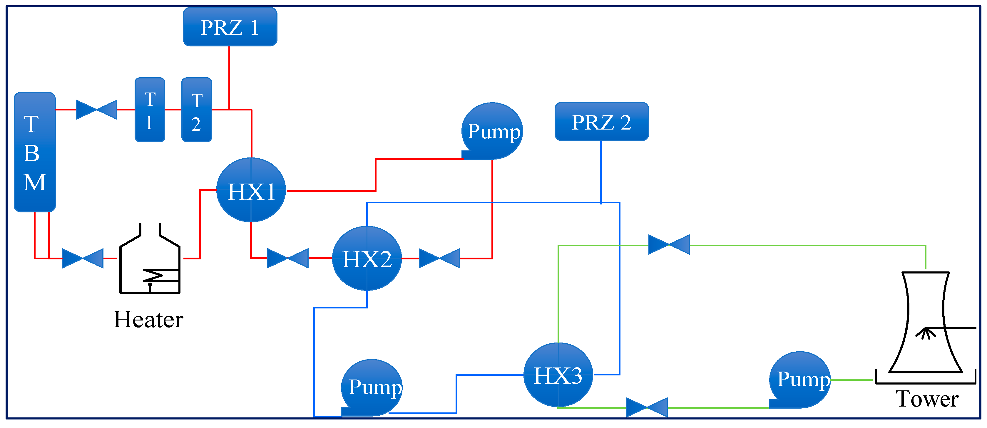
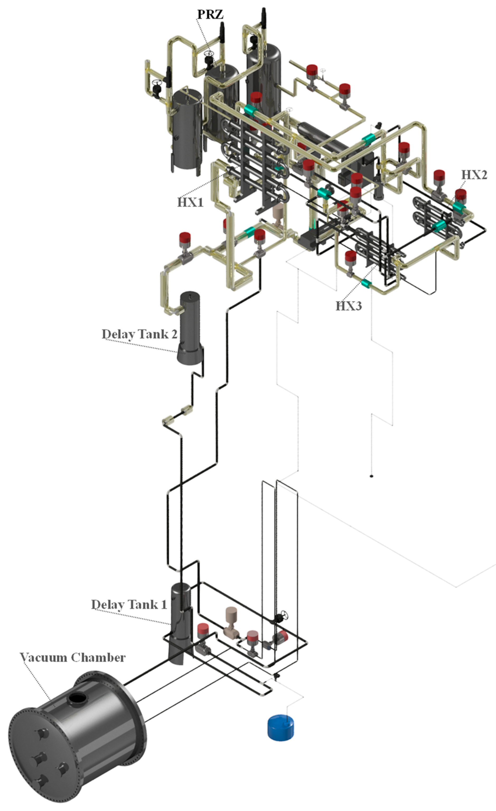
2. Water Loop Facility Objectives and Description

Water Loop is a “low power branch” of the W-HYDRA platform conceived and sized to serve as a comprehensive Integral Test Facility for the WCS of the ITER WCLL TBM. Its design replicates the functions, layout, and components of the WCS to enable full-scale thermal-hydraulic and structural testing of WCLL TBM mock-ups and their ancillary system. The primary objectives include characterizing specific components, assessing overall circuit performance, evaluating procedures, and gathering essential data for validating models and numerical codes.
Furthermore, the flexibility of the facility will allow the thermal-hydraulic and thermo-mechanical testing of various BB sub-components using specifically designed mock-ups, such as First Wall (FW), Breeding Zone (BZ), manifolds, etc. The FW test section will allow the investigation of the cooling system based on water at PWR conditions flowing in asymmetrically heated squared channels. The BZ manifold, instead, aims at testing the mass flow distribution among the parallel channels fed by the manifold. The experimental campaigns of both the mock-ups will provide experimental data useful for the validation and verification of the numerical models used during the design phase. Both nominal and accidental conditions will be addressed by experimental campaigns adopting the same control logics of the ITER WCS. This approach allows the verification and validation of the numerical models set up during the preconceptual and conceptual design phases. Notably, Loss of Coolant Accident (LOCA) and Loss of Flow Accident (LOFA) scenarios occurring in the ITER WCS circuit are going to be investigated to collect valuable information on the system behavior.
The WL, whose main parameters are collected in Table 1, is a three-loop facility capable of delivering water at pressurized water reactor (PWR) conditions to a test section placed within a vacuum chamber. Specifically, the WL provides water at 15.5 MPa and 295 °C, matching the thermal-hydraulic requirements of both the WCLL BB and TBM. The same test section can be also coupled with the LIFUS5/Mod4 facility to investigate the water/PbLi reaction. To replicate the heat flux experienced by both the TBM and blanket FW, the WL features an electron beam (EB) gun installed in the dedicated vacuum chamber. This EB gun can deliver a nominal power of 0.5 MW/m² on an area of 0.8 m² and up to 5 MW/m² on around 10% of the mock-up surface in short transient. This infrastructure will be used to reproduce the heat flux acting on the First Wall of the DEMO BB due to plasma radiation during the flat-top operation. Moreover, the presence of an EB gun facilitates the investigation of various effects, such as thermal cycling fatigue, as well as localized overheating of FW regions, assessing the response of coolant, structural materials, and armor materials.

2.1. WL Primary System

The primary loop reproduces the functions, layout, and thermo-dynamic conditions of the ITER WCS. It is designed to provide water at 15.5 MPa and 295 °C to the test section. The mass flow rate design value reported in Table 1 has been inferred from the test section working with the highest requirements, i.e., the 3.74 kg/s mass flow rate required to cool down the approximately 750 kW faced by the WCLL-TBM mock-up.
The Water Loop facility schematization is illustrated in red solid lines in Figure 1. It is an eight-shaped water circuit with a hairpin heat exchanger acting as an economizer (HX1) located at the center of the circuit.
The fluid undergoes purification through a filter and is routed through the loop by a centrifugal pump. Subsequently, after a preheating in the economizer, water is further heated with an electric heater (Heater) up to the design temperature of 295 °C. It is then ready to be sent towards the test section. Water returning from the test section (typically at higher temperatures, e.g., 328 °C in the case of TBM) passes through two tanks (T1 and T2) designed to replicate the ITER WCS delay tanks, and it is then cooled down to 110 °C by the cold side of the economizer (HX1 shell side), and through another hairpin cooler (HX2) thermally connecting primary and secondary water circuits. The fluid, cooled down to 110 °C, is then redirected towards the pump. The pressurizer (PRZ 1), common with the STEAM facility, is connected to the hot leg between the second delay tank (T2) and the economizer (HX1). It is equipped with an electrical heater, a spray system, a pilot-operated relief valve (PORV) and a safety relief valve (SRV). Fluid expelled by the valves is collected inside a relief tank (not reported in the simplified scheme) that facilitates the collection and the suppression of the discharged steam. In order to maintain high fidelity of the geometry loop with respect to the ITER WCS, the WL primary loop is mainly arranged on two levels, as shown in Figure 2.

2.2. WL Secondary System

The secondary WL loop (blue solid lines in Figure 1) is designed to transfer heat from the primary to the tertiary loop. It also reproduces the WCLL TBM secondary loop, which is in charge of avoiding the contamination of the ITER CCWS with radioactive water in case of an accident occurring to the HX2.
This circuit is mainly composed by a centrifugal pump, a filter, the primary loop cooler (HX2), and the heat exchanger connecting this circuit with the tertiary loop (HX3). The pressure is regulated by a steam pressurizer (PRZ2), on top of which a PORV and an SRV allow the discharge of steam in the relief tank in case of overpressures. An electric heater is placed inside the pressurizer to supply heat and increase the pressure in case of low pressure, while a spray system is activated in case of high pressure.
The loop will be operated at 2.0 MPa, with water temperatures ranging from 65 °C to 128 °C. The design pressure for this circuit has been set at 2.5 MPa, while the design temperature is equal to 220 °C.

2.3. WL Tertiary System

The tertiary loop, represented by the green solid lines in Figure 1, serves as the ultimate heat sink of the W-HYDRA platform. Thermal power is transferred to this loop via the heat exchanger HX3 and it is subsequently dissipated into the environment through a cooling tower (Tower). Circulation within the loop is ensured by a pump and a regulation valve is envisaged to regulate the mass flow rate. Since the cooling tower is designed to operate with an open cycle, water is going to be continuously integrated with the support of a water treatment system.

3. Numerical Analyses in Support of the Design

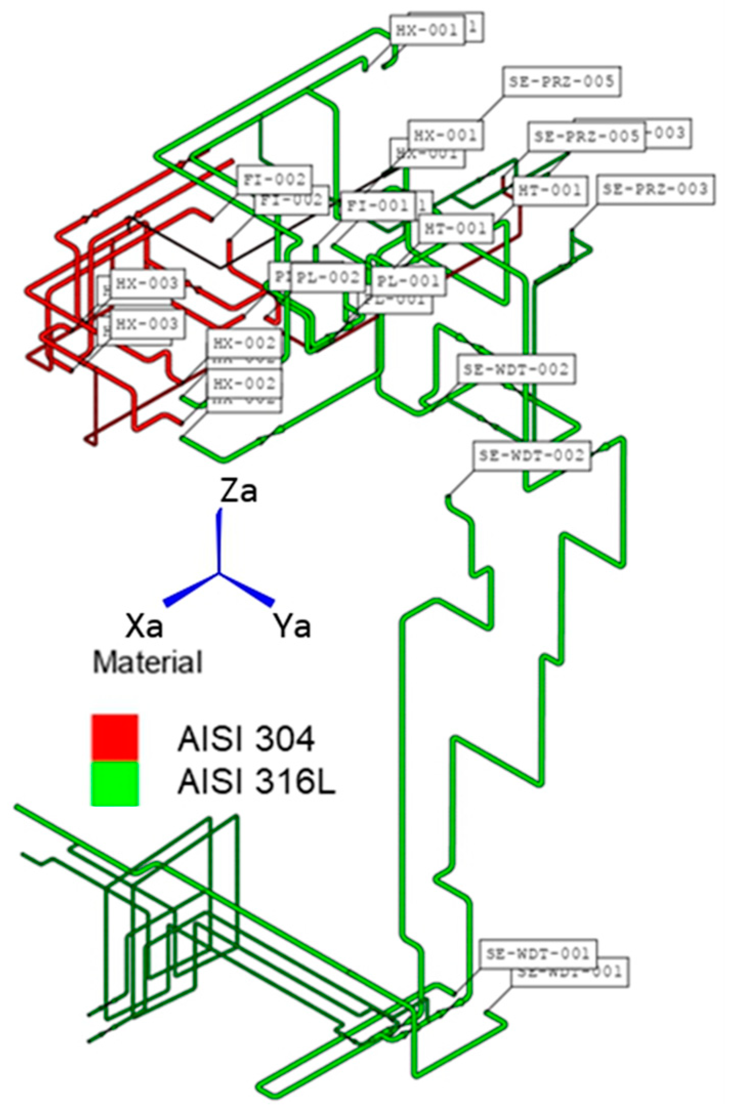
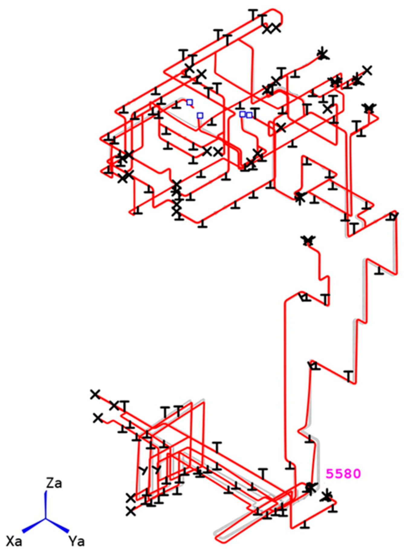
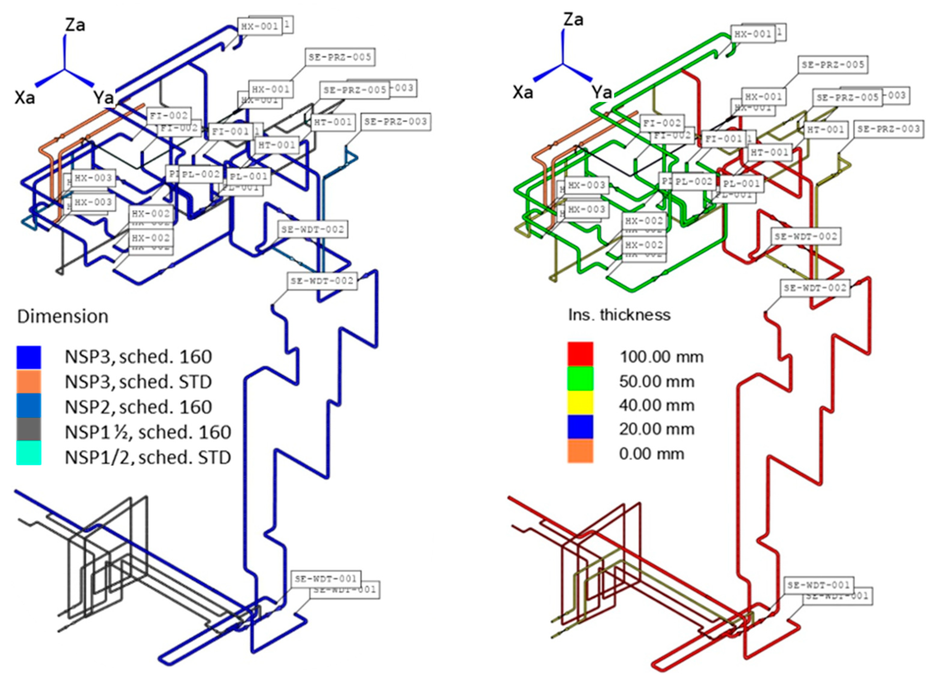
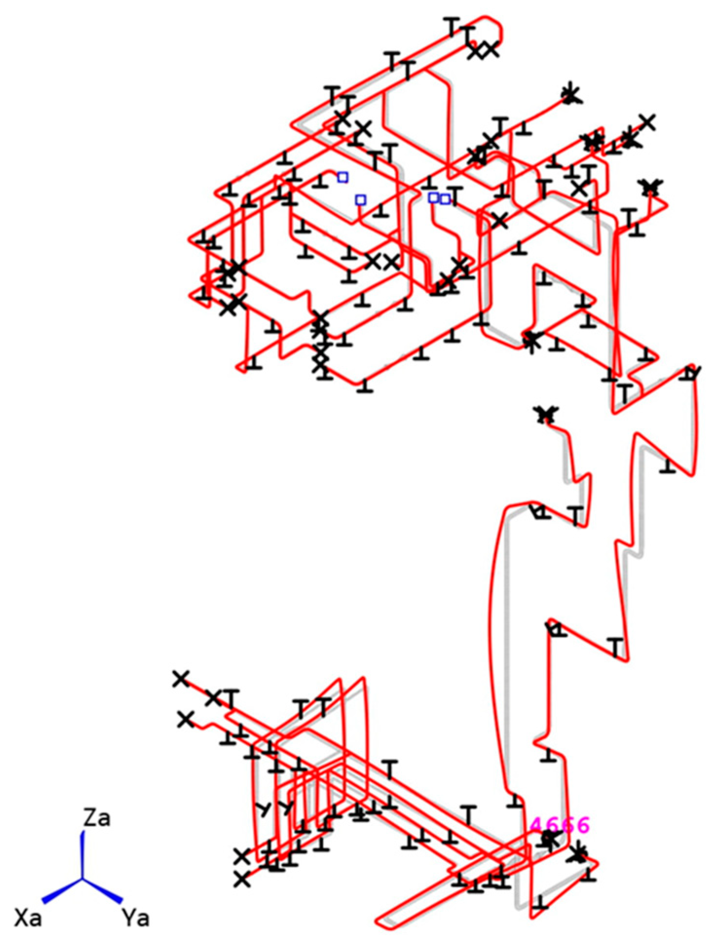
3.1. Pipe Stress Analysis in Support of the Design

A pipe stress analysis has been performed on the Water Loop configuration shown in Figure 2 with the primary aim of verifying its structural stability and to optimize the layout. A try-and-fail approach has been followed to assess and design the support system. When necessary, further supports were installed and modifications to the existing ones have been carried out to minimize the displacements while reducing the stress level induced to the piping.

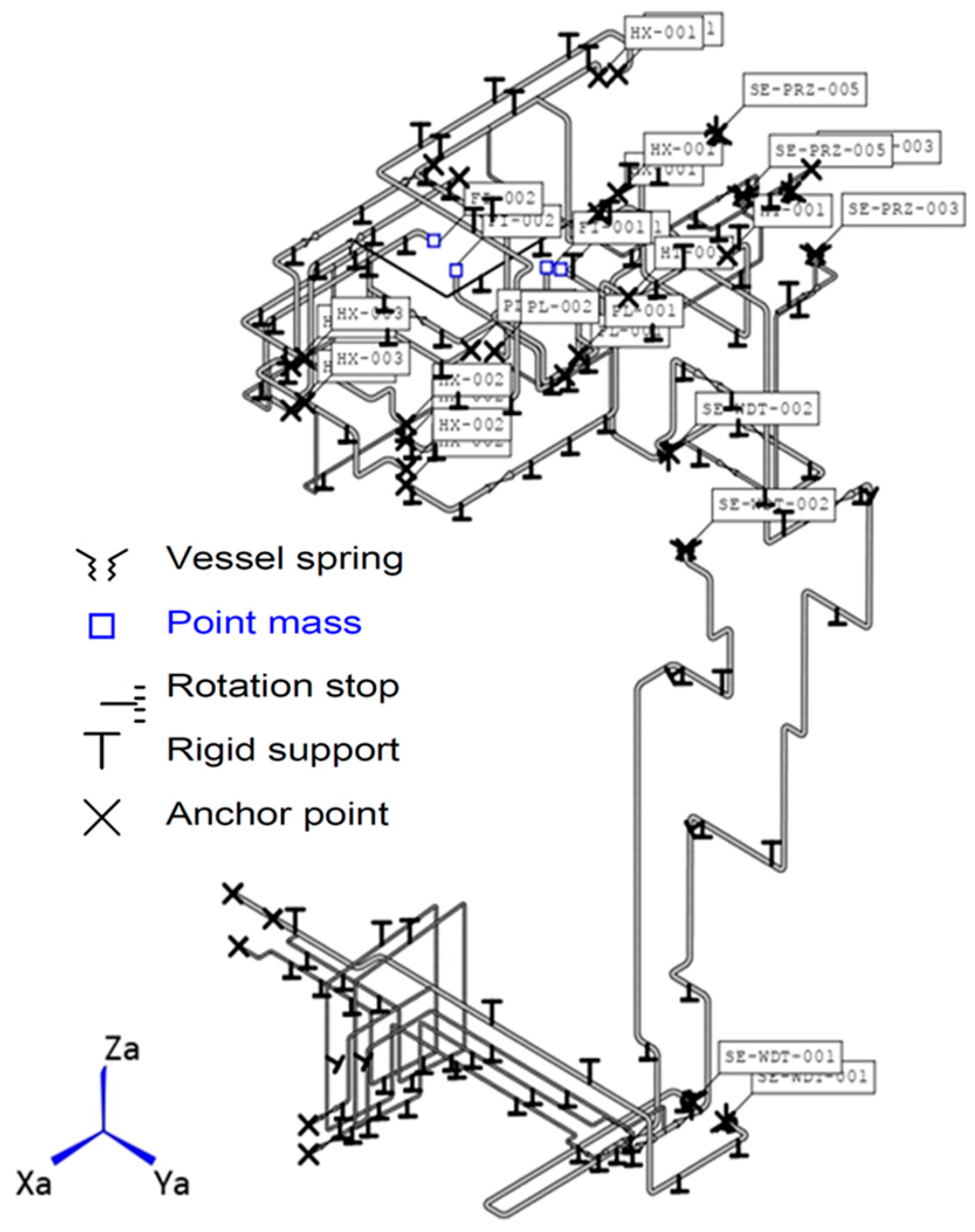
3.1.1. Numerical Model, Loads, and Boundary Conditions

The study has been carried out using the commercial code ROHR2 v33 [16]. The ASME BPVC Sect. III [17] has been adopted for the piping structural verification, considering Class II for the loop components. The assessed loading scenario is classified under Cat. I of the considered code.
Numerical models for pipe stress analyses in ROHR2 are set up as a series of 3D beam elements that create a depiction of the piping geometry, showing good accuracy of the results while requiring much less computational effort than 3D solid elements.
In ROHR2, loads can be divided into primary (composed by piping and component dead loads, internal operating pressure, and additional occasional loads such as earthquake or window loads) and secondary (linked only to the thermal expansion associated to the operating temperature) loads.
Two static load cases have been analyzed: a dead load scenario and a plasma/normal operation state (POS/NOS) Cat. I scenario, which is aligned with the ITER WCLL-TBM Water Coolant System (WCS) loading conditions [18,19]. The combination of global loads considered in the two cases are listed in Table 2.
According to the standards, the verification of the stress level considers different combinations, as follows:
-
Primary loads or sustained loads (SSL), which include the primary loads related to the load case “Dead Load” (i.e., gravity and internal pressure);
-
Secondary loads or thermal range (SE), which include only the effect of the axial thermal expansion, calculated as a combination of the two load cases “Dead Load” and “POS/NOS Cat. I”;
-
Primary plus secondary loads (STE), which consider all the loads acting during the normal operation loading scenario.
The output of the stress analysis is usually expressed in terms of displacement field and equivalent stress field (Hencky–Mises or Tresca) arising along the piping in each section under the effect of different load combinations. The structural behavior is evaluated thanks to the so-called “utilization factor” (UF), defined as the percentage ratio of the equivalent stress, σeq (expressed as a combination of primary and/or secondary stresses as to the specific design criteria), to the allowable stress, σall (defined by the design criteria and usually a function of the yield or ultimate strength of the material) [16]:
U F = σ e q σ a l l · 100
Values of UF lower than 100% mean that the considered criterion is fulfilled. For the present analyses, the utilization factor as per ASME Sect. III will be calculated under different load cases.
The primary and secondary system Water Loop model implemented in the ROHR2 code considers the connections with the main components and interfaces (Figure 3) and differentiates the structural properties according to the specific piping material (AISI 316L and AISI 304) as shown in Figure 4. The adopted dimensions of pipes and corresponding insulation are reported in Figure 5.
Following a try-and-fail iterative approach, a set of supports has been determined, adopting hangers and combinations of rigid supports, as shown in Figure 6. The provided support system has been implemented and improved in view of the results of the structural analysis. The symbols shown in Figure 6 represent the different types of connections, supports, and concentrated loads applied to the piping model.
Several combinations have been investigated, restraining one or more directions of motion in different parts of the piping to safely sustain the dead load and allowing, at the same time, thermal expansion. Regarding the connections, the attachment of a pipe to a vessel has been modeled using a proper nozzle, specifically a “vessel spring” ROHR2 component, which is able to simulate the stiffness of the nozzle based on its main dimensions. Where this is not possible, such as for pumps or heat exchangers, anchor points have been conservatively employed.
Moreover, interfaces with other systems have been modeled imposing proper mechanical restraints. Regarding special components, “unreinforced fabricated tee” and “plain bend pipe” components have been adopted for tee junctions and bends, respectively. Finally, the weight of the components included in the piping, such as valves, filters, and so on, have been included as part of the overall dead load acting on the system.
The set of supports proposed and used for the analysis, including anchor points, rigid supports, vessel springs, etc., is reported in Figure 6. In particular, starting from the existing set of support, the proposed distribution has been derived from several iterations of structural analysis and following a try-and-fail approach.
The nominal operating conditions, reported in Figure 7, in terms of pressure and temperature of the carried fluid applied to each pipe, have been defined on the basis of the corresponding loading scenario set-up for the ITER WCLL-TBM WCS [9].

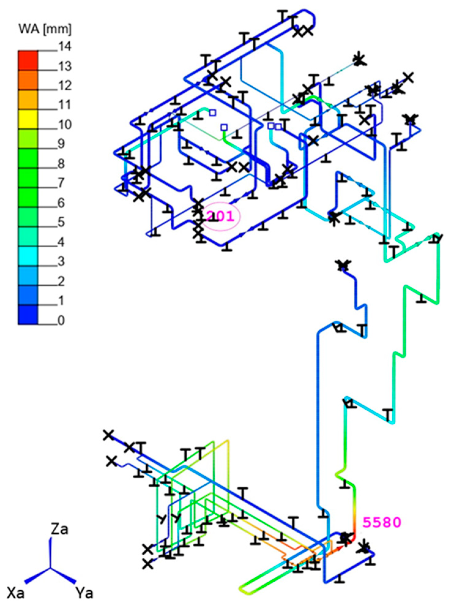
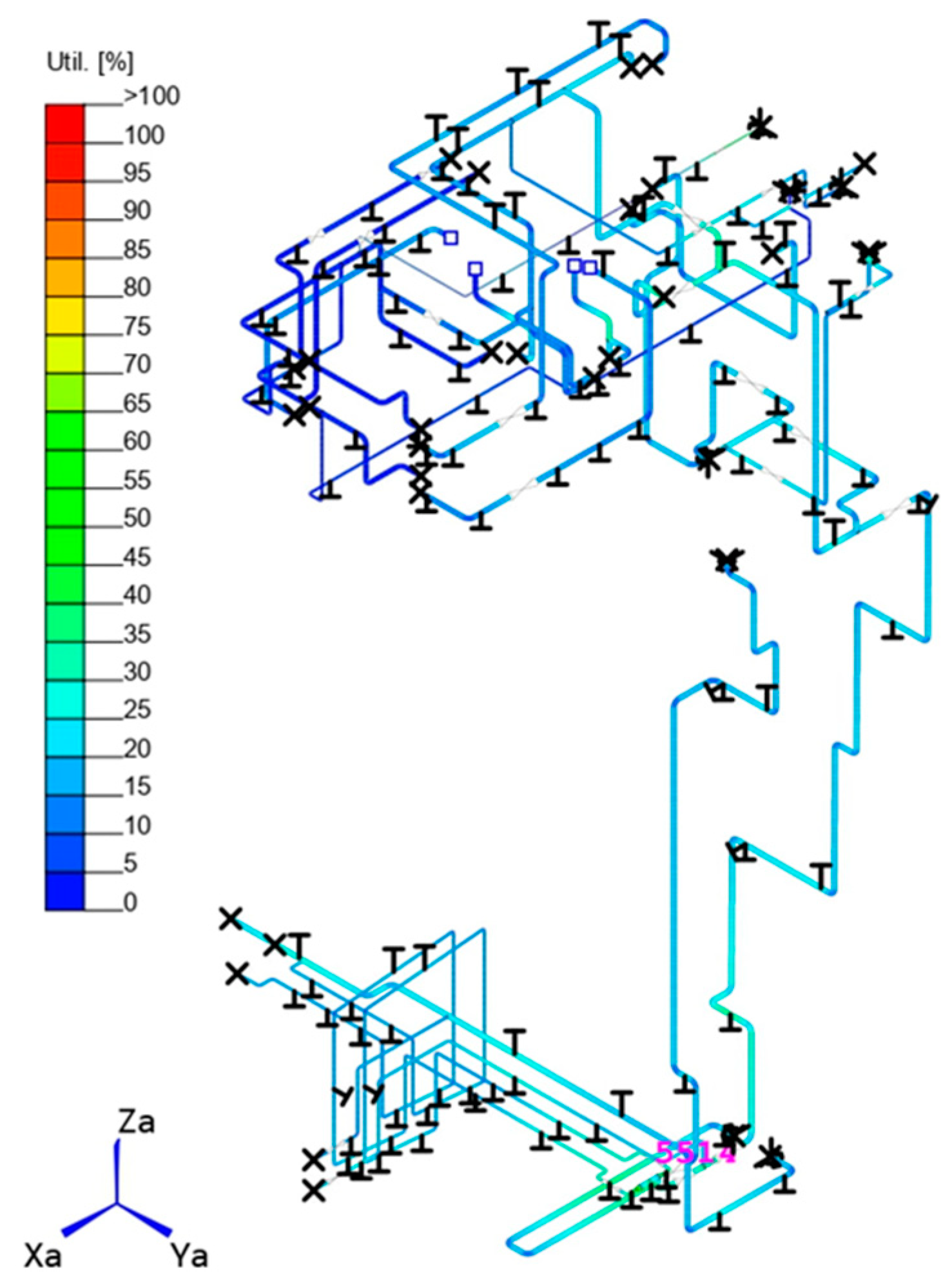
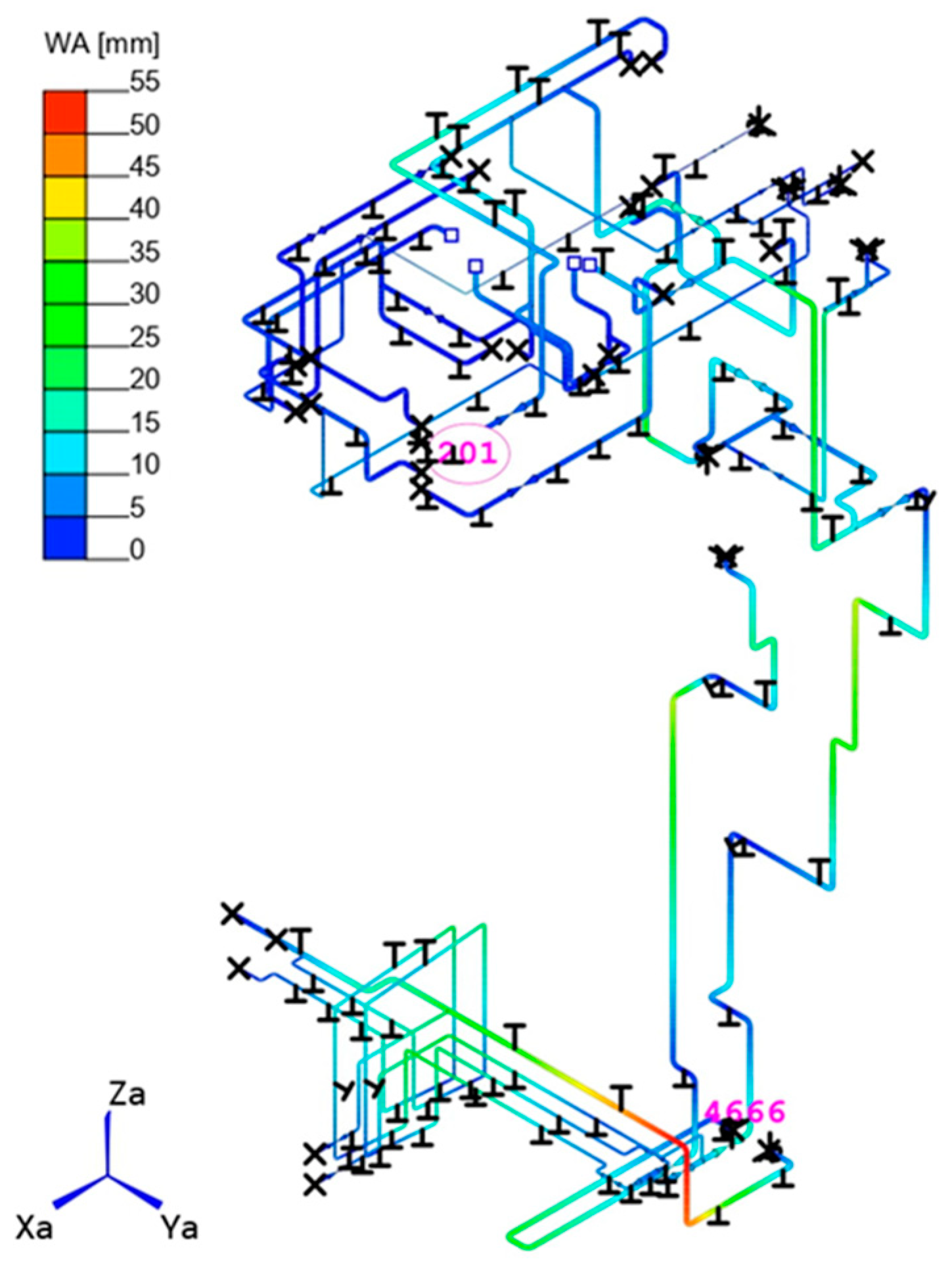
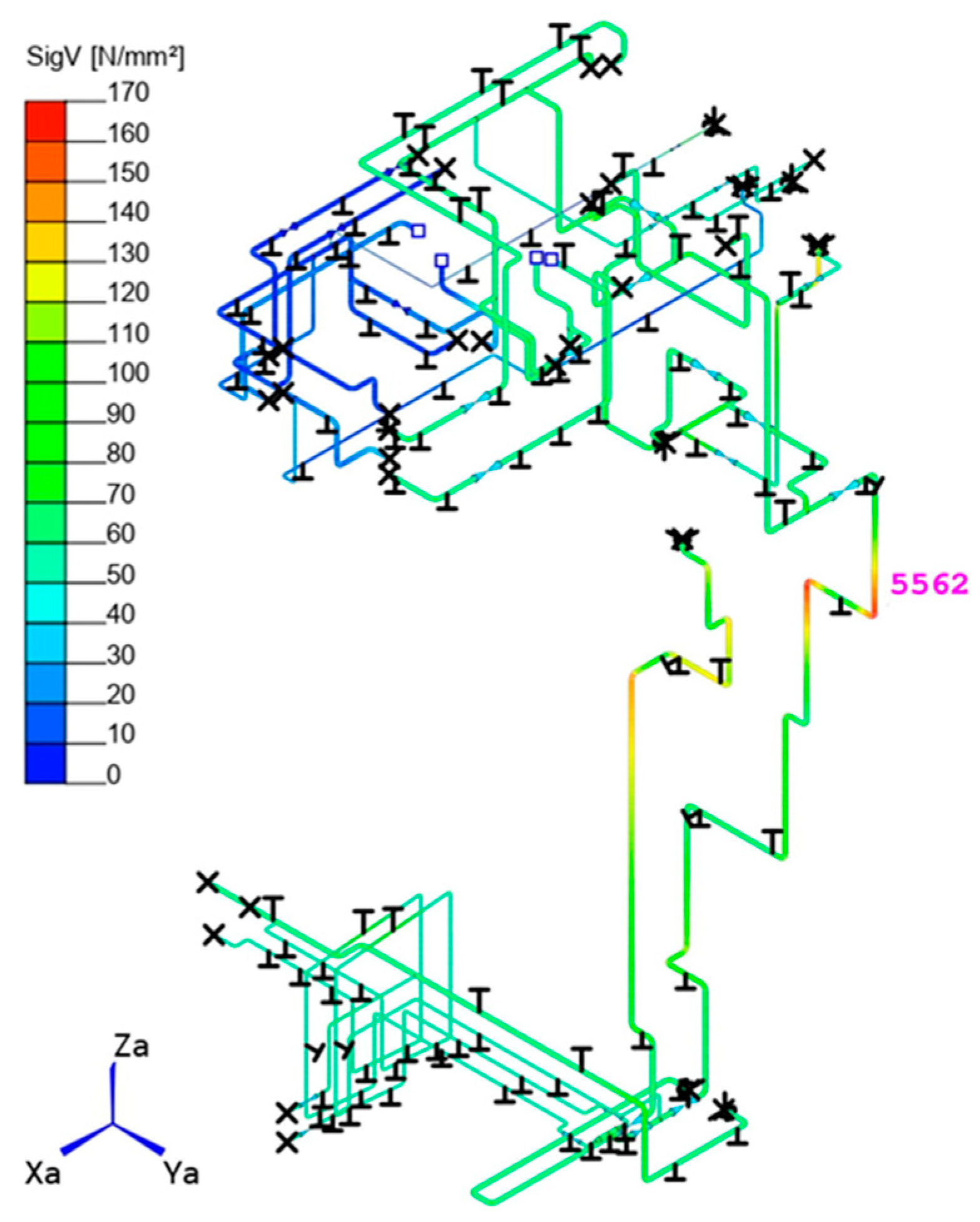
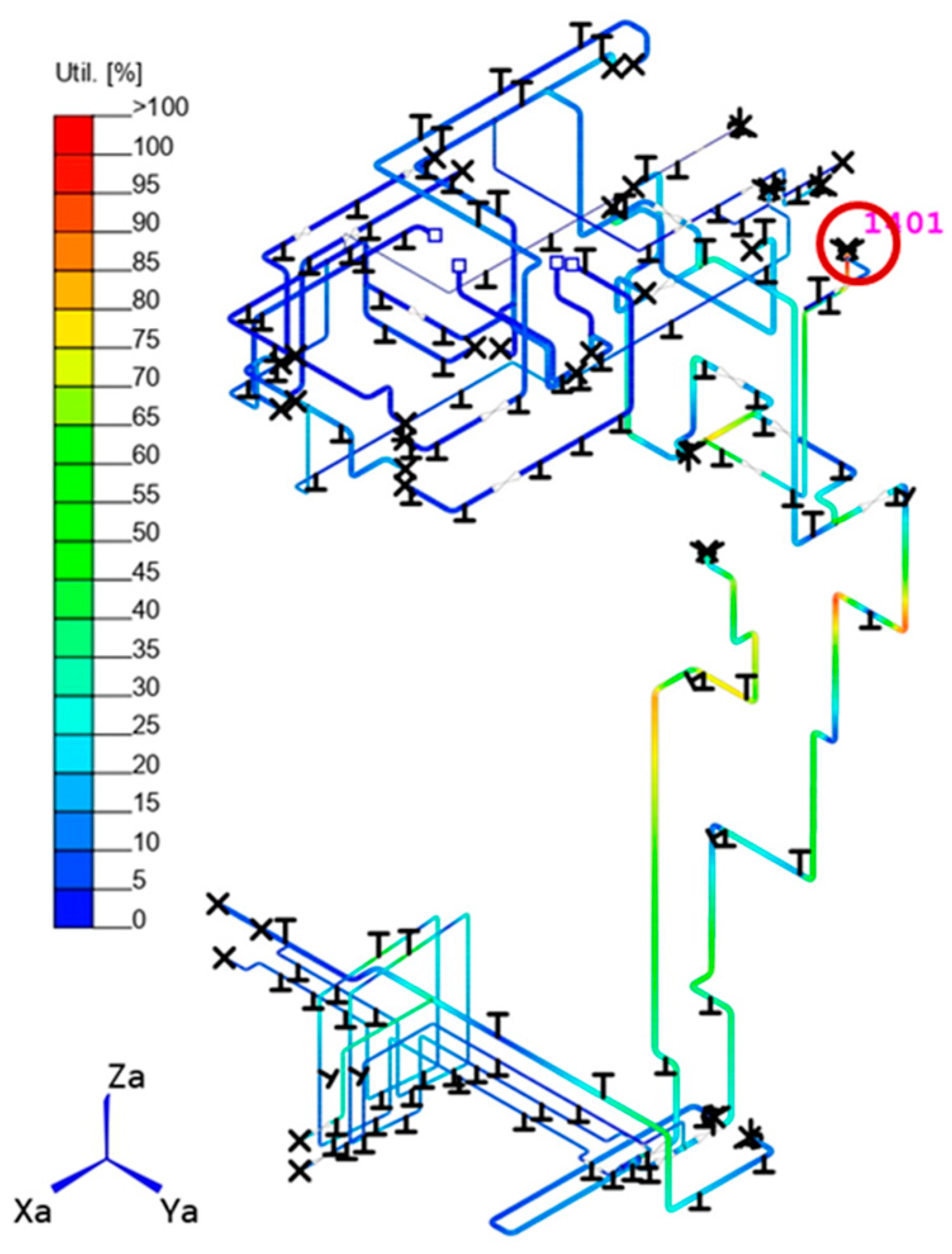
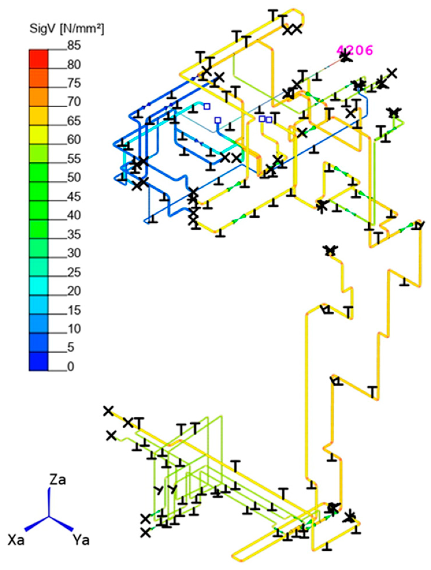
3.1.2. ROHR2 Results

The first case results regarding the dead load scenario have been expressed in terms of deformed configuration, displacements, equivalent stress field, and utilization factors computed as per ASME BPVC Sect. III Class 2. Such results are reported in Figure 8, Figure 9, Figure 10 and Figure 11, respectively, showing that that the support system of the Water Loop circuit is capable of withstanding the dead load with no particular issues. Table 3 reports the maximum values obtained for different outputs.
The second case results regarding the POS/NOS Cat. I load case have been expressed in terms of deformed configuration, displacements, equivalent stress field, and utilization factors computed as per ASME BPVC Sect. III Class 2. The related information is summarized by Figure 12, Figure 13, Figure 14, Figure 15 and Figure 16, respectively, highlighting some issues along the circuit. Specifically, a large displacement is obtained in correspondence with the pipe connected to the TBM, mainly due to the combination of high temperature and its significant length. However, the displacement could not be restrained in order to limit the thermal stresses. Concerning the stress analyses, the ASME III criteria are satisfied everywhere, either for secondary or primary plus secondary loads, with an exception in a restricted region of the piping system (circled in red in Figure 15 and Figure 16), where the utilization factor overcomes the limit. Table 4 reports the maximum values obtained for different outputs.

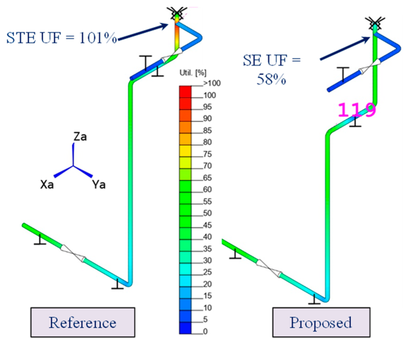
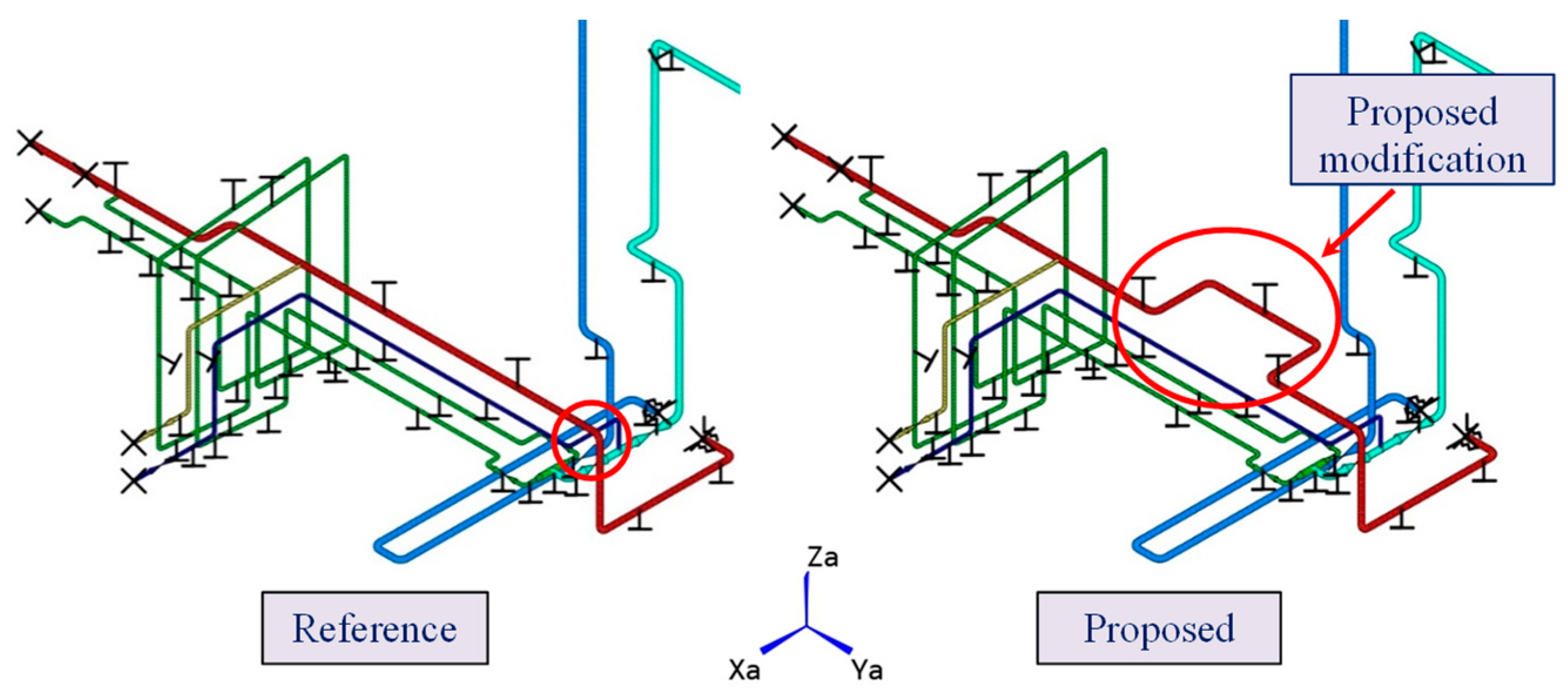
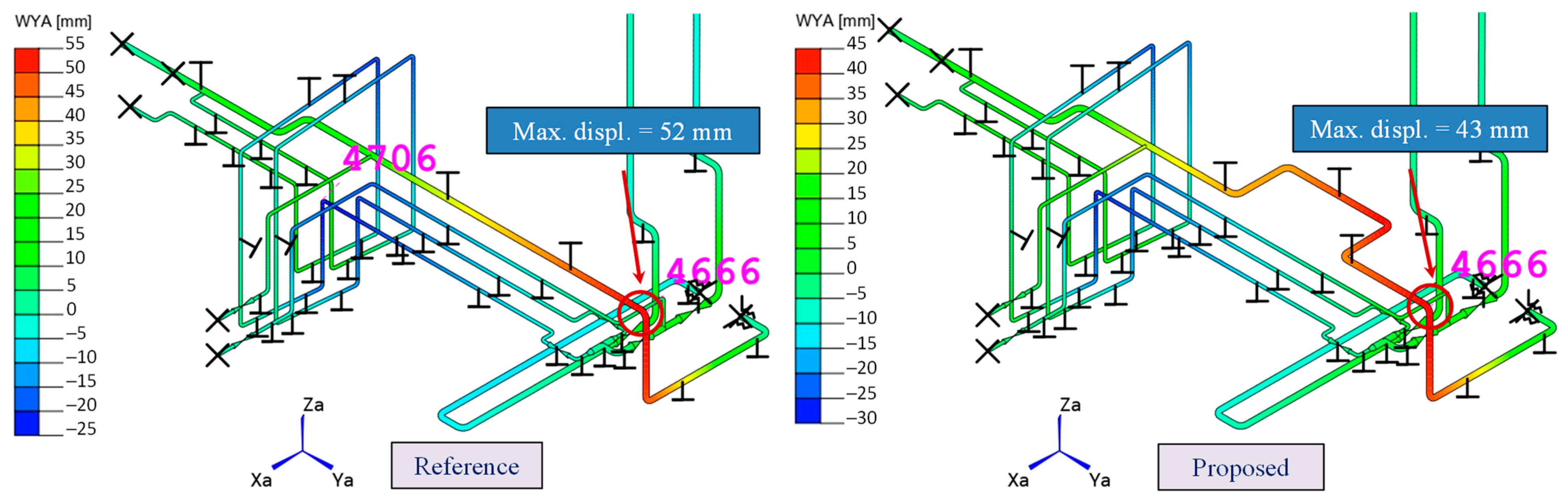
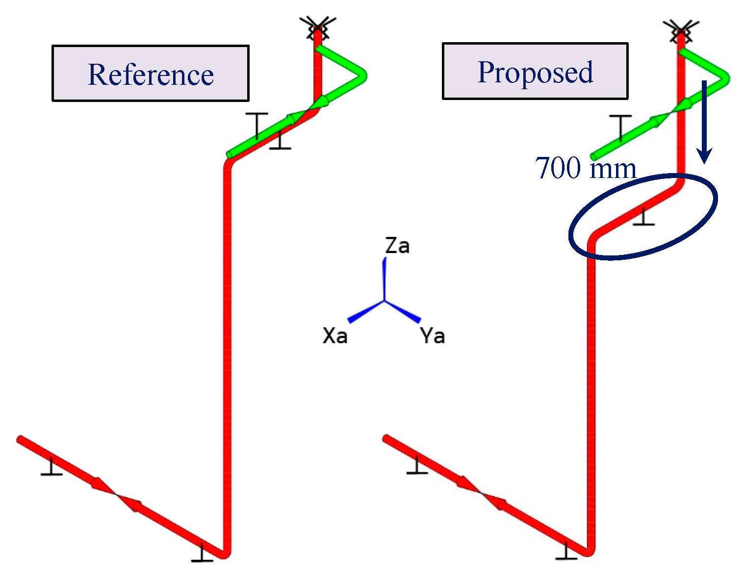
3.1.3. Investigated Layout Optimization Solutions

In pursuit of ensuring the overall system safety under various loading conditions, two minor adjustments in correspondence with the higher stress and displacement areas have been investigated, leading to the formulation and implementation of a viable solution within the ROHR2 model of the Water Loop.
The first modification involved a vertical displacement of the red pipe horizontal segment by 700 mm (Figure 17). In the reference configuration, the UF value exceeds 100% (Figure 15 and Figure 16); this occurrence primarily stemmed from the elevated operating temperatures and the proximity to a vessel junction. As demonstrated in Figure 18 and Figure 19, the adjustment resulted in a significant reduction in UF for both secondary (SE) and primary plus secondary (STE) loads, well below the critical threshold of 100%.
The second adjustment, shown in Figure 20, concerns the pipe connected to the TBM and leads to a reduction of about 1 cm in the displacements along the Y direction, as reported in Figure 21.

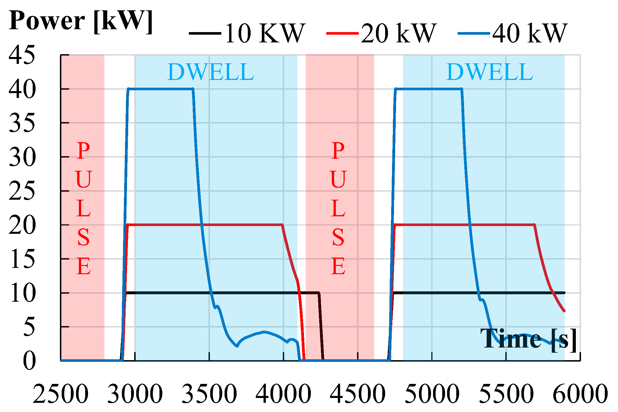
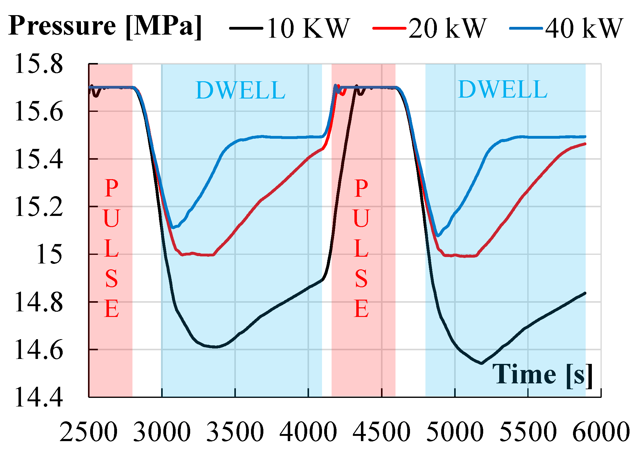
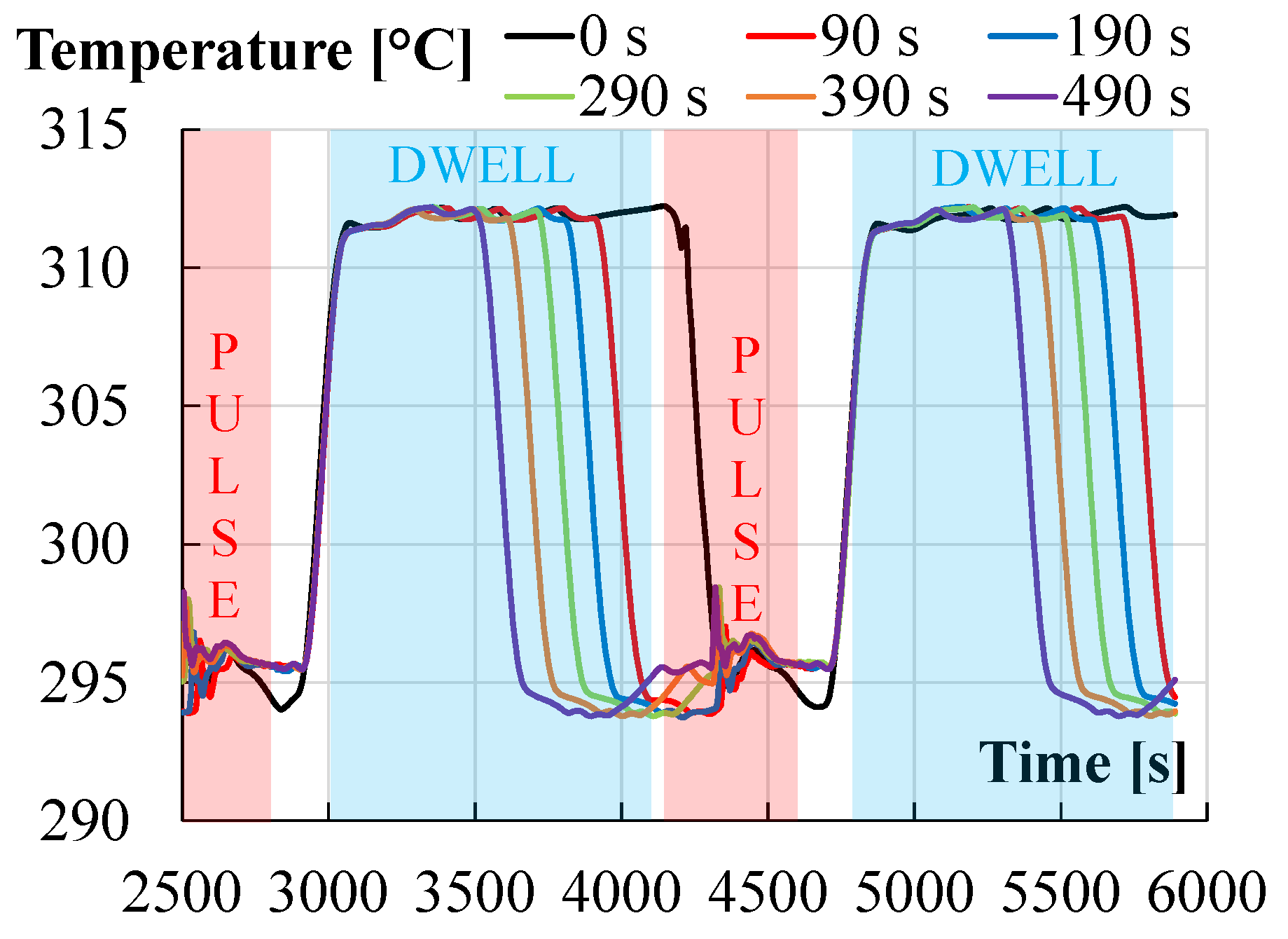
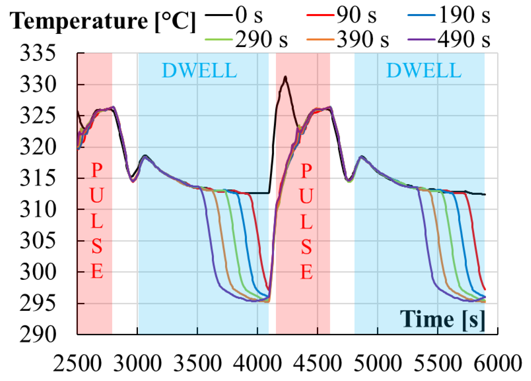
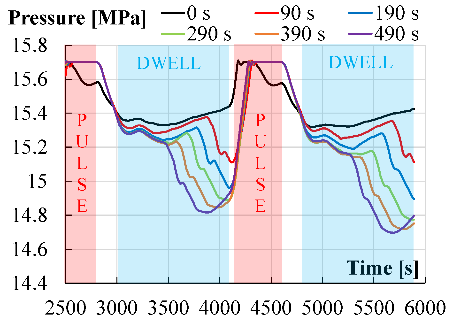
3.2. RELAP5 Analyses for the Optimization of the Facility Operation during Pulsed–Dwell–Pulsed Operation

Thermal-hydraulic (T/H) analyses in support of the WL design and optimization have been performed using the system code RELAP5/Mod3.3 [20]. In particular, the T/H behavior of the facility has been investigated during the pulse–dwell–pulse transitions [21] envisaged for a burning plasma, whose energy production is constrained in time by the inability to indefinitely sustain the variation in the current that generates the magnetic field. Selected accidents, such as the LOFA affecting the secondary side, have been also investigated [21].
The pulsed plasma regime, derived from [18,19], is characterized by a flat-top full-power state (100%; pulse phase), lasting 450 s. In the following 200 s, the power linearly ramps down to 1%, corresponding to the expected value of the BB decay heat, and remains stable in this condition (dwell time) for 1090 s. Then, the power linearly ramps up again in 60 s to 100%. These power transitions determine temperature variations that cause high thermal stresses on the components and difficulties in the regulation of the facility.
The timing used for simulation purposes is reported in Table 5. Only the rows in bold are reported in the next figures (initial steady state and the first ramp down are not shown).
Referring to Figure 1, during the pulse phase, the TBM test section receives fluid at the temperature of 295 °C (kept fixed by the heater set point) and heats it up to 328 °C. During the dwell, when only 1% of the nominal power is produced, the TBM outlet temperature tends to equalize with the inlet temperature, resulting in ΔT of approximately 0.33 °C. Consequently, Hot Leg (HL, i.e., from TBM outlet) density increases and specific volume decreases. The fluid contraction leads to a reduction in the pressurizer liquid level, causing the pressure to drop below the PRZ heaters’ set point (15.4 MPa).
The transient experienced by the pressurizer has been assessed through sensitivity analyses performed varying the PRZ heaters’ power (i.e., 10 kW, 20 kW, and 40 kW), with the primary aim of mitigating pressure excursions resulting from the alternation of pulse and dwell phases. The low-pressure signal triggers the PRZ heaters and their power quickly increases to prevent the system depressurization (Figure 22). The higher the PRZ heaters’ power, the quicker the pressure value is restored within its acceptability range (Figure 23) and the sooner the heaters’ power is switched off.
Although, the occurrence of the pulse leads to an increase in the TBM outlet temperature, accompanied by fluid expansion (density decreases), resulting in rising PRZ level and increasing the pressure above the spray set point (15.7 MPa). Higher PRZ heater power determines higher pressure established in the loop at the end of the dwell phase and consequent faster pressurization. The pressure peak is limited by the spray intervention, which takes longer for higher PRZ heater power.
Additional sensitivity analyses have been conducted with a PRZ heater power of 10 kW to explore safer operational strategies during the rapid power fluctuations, with the aim of preventing system depressurization during the pulse phase. Specifically, in “case 0” (black in Figure 24, Figure 25 and Figure 26) the heater set point has been switched from 295 °C to 311.5 °C (i.e., the TBM average temperature, calculated as (295 + 328)/2 = 311.5 °C) during the dwell phase to limit the fluid density reduction. As a result, both cold and hot leg temperature tends to 311.5 °C during the dwell phase, meaning that the temperature gradient that the hot leg should experience is halved between cold and hot leg. With the ramp up, heater set point is restored at 295 °C. Therefore, the cold leg (CL) temperature drops to 295 °C (Figure 24). Instead, a temperature peak of approximately 333 °C can be observed for the HL, as shown in Figure 25, resulting in an overpressure (Figure 26), limited by the spray intervention.
To avoid the temperature peak, further analyses have been performed, reverting the heater set point from 311.5 to 295 °C before the dwell phase ends. In particular, this modification has been implemented 90 s, 190 s, 290 s, 390 s, and 490 s before the pulse (b.p.) to allow the HL temperature to return to its nominal value. Results indicate that CL temperature (Figure 24) undergoes a thermal cycling of approximately half of the nominal (pulse phase) ΔT (i.e., 16.5 °C). In contrast, the HL (Figure 25) experiences a ΔT increasing with the heater anticipation time, up to its nominal (pulse phase, i.e., 33 °C) value for b.p. greater than 290 s. However, this allows the HL temperature to not exceed its limit. Regarding loop pressure, except for “case 0”, the longer the 311.5 °C set point is maintained, the less significant the depressurization is; switching the set point to 295 °C only 90 s before the pulse contains the pressure reduction above 15.2 MPa but, nonetheless, it results in a pressure peak that determines the spray intervention (Figure 26).
Regardless of how the circuit is managed, pressure fluctuations triggering spray activation are inevitable. The most reasonable choice would be to install an electric heater at the TBM outlet to maintain 328 °C as a fixed set point for the hot leg temperature, thus avoiding pressure excursions associated with density variations. However, this would result in a significant increase in the complexity of the facility and in an increase in the cost. For this reason, the adoption of 40 kW electric heaters in the pressurizer is preferred among the strategies considered because it exhibits lower pressure cycling (the same overpressure as the other but a contained depressurization).

4. Conclusions

Water Loop, as a part of the W-HYDRA infrastructure, represents a comprehensive platform for ITER WCLL TBM WCS testing at the full scale. It will provide a test bed for the WCLL BB, hosting several mock-ups for the investigation of phenomena and components. It is strategic for the development of relevant design, technology, and licensing of ITER’s WCLL WCS.
The pipe stress analysis of the Water Loop piping system has been performed under the normal operation loading conditions of the ITER WCLL-TBM WCS. The supports system has been implemented and modified to achieve dual objectives: minimizing displacements while mitigating stresses within the piping system. The outcomes of the pipe stress analysis reveal that the system exhibits overall stability and functionality, with no significant concerns. However, localized areas displayed elevated stress levels. To enhance the structural response of the system in these specific stress-prone regions, minor modifications have been proposed. These layout adjustments have been introduced and assessed, showing benefits in the predicted stress and displacements.
Thermal hydraulic analyses have been performed to investigate the facility response to the rapid transitions between pulsed and dwell phases, with a particular focus on the pressurizer behaviour. During the dwell phase, the power reduction determines the hot leg temperature decrease, approaching the cold leg temperature. The correspondent density variation causes the pressurizer pressure to decrease, triggering the PRZ electrical heaters. In correspondence with the pulse, the increase in hot leg density leads to an overpressure, which is, in turn, dealt by the spray. Several sensitivity analyses have been performed, revealing that, while it is impossible to prevent pulse overpressure, the extent of the depressurization can be limited by increasing the PRZ heaters’ maximum power or by modifying the heater set point during the dwell phase.
Further thermal-hydraulic and thermo-mechanic analyses will be performed to finalize the design of the main components and the layout of the WL facility. The facility construction is supposed to be completed by the end of 2024 and commissioning tests will follow.

Author Contributions

Conceptualization, A.V., B.G., M.E., I.C., E.V., P.A. (Pietro Arena) and A.D.N.; software, B.G., C.C., I.C., P.L., N.B. and A.T.; writing—original draft preparation, A.V. and E.V., writing—review and editing, A.C., F.G. (Fabio Giannetti), N.F., F.G. (Francesco Galleni) and P.A.D.M.; supervision, A.D.N. and P.A. (Pietro Agostini); project administration, A.D.N. and P.A. (Pietro Arena); funding acquisition, A.D.N. and P.A. (Pietro Agostini). All authors have read and agreed to the published version of the manuscript.

Funding

This research was funded by the European Union via the Euratom Research and Training Programme, grant number 101052200.

Data Availability Statement

Data are contained within the article.

Acknowledgments

This work has been carried out within the framework of the EUROfusion Consortium. Views and opinions expressed are, however, those of the author(s) only and do not necessarily reflect those of the European Union or the European Commission. Neither the European Union nor the European Commission can be held responsible for them.

Conflicts of Interest

The authors declare no conflict of interest.

References

  1. Muratov, V.P.; Saksagansky, G.L.; Filatov, O.G. ITER—International Thermonuclear Experimental Reactor. In Fundamentals of Magnetic Thermonuclear Reactor Design; Woodhead Publishing Series in Energy; Woodhead Publishing: Sawston, UK, 2018; pp. 39–67. [Google Scholar] [CrossRef]
  2. Boccaccini, L.V.; Arbeiter, F.; Arena, P.; Aubert, J.; Buhler, L.; Cristescu, I.; Del Nevo, A.; Emboli, M.; Forest, L.; Harrington, C.; et al. Status of maturation of critical technologies and systems design: Breeding blanket. Fusion Eng. Des. 2022, 179, 113116. [Google Scholar] [CrossRef]
  3. Ibarra, A.; Kurtz, R. ITER-TBM and Blanket Programs toward DEMO. In Proceedings of the 3rd IAEA DEMO Programme Workshop, Hefei, China, 11–14 May 2015; Available online: https://nucleus.iaea.org/sites/fusionportal/Technical%20Meeting%20Proceedings/3rd%20DEMO/website/talks/May%2013%20Sessions/Ibarra_A%20Intro.pdf (accessed on 8 July 2022).
  4. Giancarli, L.M.; Bravo, X.; Cho, S.; Ferrari, M.; Hayashi, T.; Kim, B.-Y.; Leal-Pereira, A.; Martins, J.-P.; Merola, M.; Pascal, R.; et al. Overview of recent ITER TBM Program activities. Fusion Eng. Des. 2020, 158, 111674. [Google Scholar] [CrossRef]
  5. Federici, G. An overview of the EU Breeding Blanket design strategy as an integral part of the DEMO design effort. Fusion Eng. Des. 2019, 141, 30–42. [Google Scholar] [CrossRef]
  6. Ricapito, I.; Cismondi, F.; Federici, G.; Poitevin, Y.; Zmitko, M. European TBM programme: First elements of RoX and technical performance assessment for DEMO breeding blankets. Fusion Eng. Des. 2020, 156, 111584. [Google Scholar] [CrossRef]
  7. Arena, P.; Del Nevo, A.; Moro, F.; Noce, S.; Mozzillo, R.; Imbriani, V.; Giannetti, F.; Edemetti, F.; Froio, A.; Savoldi, L.; et al. The demo water-cooled lead–lithium breeding blanket: Design status at the end of the pre-conceptual design phase. Appl. Sci. 2023, 11, 11592. [Google Scholar] [CrossRef]
  8. Donné, A.J.H. European roadmap to fusion energy. In Proceedings of the 2018 Symposium on Fusion Technology (SOFT), Giardini Naxos, Italy, 16–21 September 2018. [Google Scholar]
  9. Tincani, A.; Arena, P.; Bruzzone, M.; Catanzaro, I.; Ciurluini, C.; Del Nevo, A.; Di Maio, P.A.; Forte, R.; Giannetti, F.; Lorenzi, S.; et al. Conceptual design of the main Ancillary Systems of the ITER Water Cooled Lithium Lead Test Blanket System. Fusion Eng. Des. 2021, 167, 112345. [Google Scholar] [CrossRef]
  10. EUROfusion. Available online: https://www.euro-fusion.org/ (accessed on 30 September 2023).
  11. Vannoni, A.; Lorusso, P.; Eboli, M.; Giannetti, F.; Ciurluini, C.; Tincani, A.; Marinari, R.; Tarallo, A.; Del Nevo, A. Development of a Steam Generator Mock-Up for EU DEMO Fusion Reactor: Conceptual Design and Code Assessment. Energies 2023, 16, 3729. [Google Scholar] [CrossRef]
  12. Ciattaglia, S.; Federici, G.; Barucca, L.; Stieglitz, R.; Taylor, N. EU DEMO safety and balance of plant design and operating requirements: Issues and possible solutions. Fusion Eng. Des. 2019, 146 Pt B, 2184–2188. [Google Scholar] [CrossRef]
  13. Ciurluini, C.; Vannoni, A.; Del Moro, T.; Lorusso, P.; Tincani, A.; Del Nevo, A.; Barucca, L.; Giannetti, F. Thermal-hydraulic assessment of Once-Through Steam Generators for EU-DEMO WCLL Breeding Blanket primary cooling system application. Fusion Eng. Des. 2023, 193, 113688. [Google Scholar] [CrossRef]
  14. Tincani, A.; Ciurluini, C.; Nevo, A.D.; Giannetti, F.; Tarallo, A.; Tripodo, C.; Cammi, A.; Vannoni, A.; Eboli, M.; Del Moro, T.; et al. Conceptual Design of the Steam Generators for the EU DEMO WCLL Reactor. Energies 2023, 16, 2601. [Google Scholar] [CrossRef]
  15. Eboli, M. The LIFUS5 separate effect test facility experimental programme. Nucl. Eng. Des. 2023, 411, 112425. [Google Scholar] [CrossRef]
  16. ROHR2, Version 33; SIGMA Ingenieurgesellschaft mbH: Unna, Germany, 2021. Available online: www.rohr2.de (accessed on 30 June 2022).
  17. BPVC.III.1.NC-2015; Boiler and Pressure Vessel Code—Section III: Rules for Construction of Nuclear Power Plant Components, Division 1, Subsection NC: Class 2 Components. The American Society of Mechanical Engineers (ASME): New York, NY, USA, 2015.
  18. Ciurluini, C.; Giannetti, F.; Tincani, A.; Del Nevo, A.; Caruso, G.; Ricapito, I.; Cismondi, F. Thermal-hydraulic modeling and analysis of the Water Cooling System for the ITER Test Blanket Module. Fusion Eng. Des. 2020, 158, 111709. [Google Scholar] [CrossRef]
  19. Ciurluini, C.; Narcisi, V.; Tincani, A.; Ferrer, C.O.; Giannetti, F. Conceptual design overview of the ITER WCLL Water Cooling System and supporting thermal-hydraulic analysis. Fusion Eng. Des. 2021, 171, 112598. [Google Scholar] [CrossRef]
  20. ISL Inc. RELAP5/Mod3.3 Code Manual Volume I: Code Structure, System Models, and Solution Methods; ISL Inc. (Nuclear Safety Analysis Division): San Diego, CA, USA, 2003. [Google Scholar]
  21. Gonfiotti, B.; Ciurluini, C.; Giannetti, F.; Arena, P.; Del Nevo, A. Assessment of the relevancy of ENEA Water Loop facility with respect to ITER WCLL TBS Water Cooling System by considering their thermal-hydraulic performances during selected transient conditions. In Proceedings of the ISFNT-15 Conference, Las Palmas de Gran Canaria, Spain, 10–15 September 2023. [Google Scholar]
Figure 1. Water Loop facility schematization.
Energies 16 07746 g001
Figure 2. Water Loop facility CAD: primary and secondary systems.
Energies 16 07746 g002
Figure 3. WL model interfaces.
Energies 16 07746 g003
Figure 4. Assigned materials.
Energies 16 07746 g004
Figure 5. Pipe dimensions and insulation.
Energies 16 07746 g005
Figure 6. Proposed set of supports.
Energies 16 07746 g006
Figure 7. Operating conditions.
Energies 16 07746 g007
Figure 8. Dead load. Deformed configuration (ISO amplification factor = 20).
Energies 16 07746 g008
Figure 9. Dead load. Displacement field.
Energies 16 07746 g009
Figure 10. Dead load. Von Mises stress field.
Energies 16 07746 g010
Figure 11. Utilization factor for SSL (primary loads) as per ASME III Class 2.
Energies 16 07746 g011
Figure 12. POS/NOS Cat.I. Deformed configuration (ISO amplification factor = 10).
Energies 16 07746 g012
Figure 13. POS/NOS Cat.I. Displacement field.
Energies 16 07746 g013
Figure 14. POS/NOS Cat.I. Von Mises stress field.
Energies 16 07746 g014
Figure 15. Utilization factor for SE (secondary loads) as per ASME III Class 2.
Energies 16 07746 g015
Figure 16. Utilization factor for STE (primary plus secondary loads) as per ASME III Class 2.
Energies 16 07746 g016
Figure 17. Proposed modification to the line connected to SE-PRZ-003.
Energies 16 07746 g017
Figure 18. SE UF comparison between the reference pipe and the proposed modification.
Energies 16 07746 g018
Figure 19. STE UF comparison between the reference pipe and the proposed modification.
Energies 16 07746 g019
Figure 20. Proposed modification to the line connected to the TBM.
Energies 16 07746 g020
Figure 21. Displacement comparison between the reference pipe and the proposed modification.
Energies 16 07746 g021
Figure 22. PRZ heater power evolution in pulsed operation at different PRZ heater maximum powers.
Energies 16 07746 g022
Figure 23. Pressurizer pressure evolution in pulsed evolution at different PRZ heater maximum powers.
Energies 16 07746 g023
Figure 24. TBM inlet temperature evolution in pulsed operation. Legend refers to the time before pulse in correspondence to which the heater set point is switched from 311.5 °C to 295 °C.
Energies 16 07746 g024
Figure 25. TBM outlet temperature evolution in pulsed operation. Legend refers to the time before pulse in correspondence to which the heater set point is switched from 311.5 °C to 295 °C.
Energies 16 07746 g025
Figure 26. Pressurizer pressure evolution in pulsed operation. Legend refers to the time before pulse in correspondence to which the heater set point is switched from 311.5 °C to 295 °C.
Energies 16 07746 g026
Table 1. WL facility main data.
Primary System
1Max. electrical heating powerkW1000
2Max. EB gun powerkW800
3Max. Pressurizer (PRZ) heaters powerkW12
4Design pressureMPa18.5
5Design coolant temperature°C350
6Max. pumping headm169
7Nominal mass flow ratekg/s3.74
8Structural Material--AISI316L
Secondary System
9Max. PRZ heaters powerkW2
10Design pressureMPa2.5
11Design coolant temperature°C220
12Max. pumping headm36
13Nominal mass flow ratekg/s4.3
14Structural Material--AISI316L
Tertiary System
15Design pressureMPa0.6
16Design coolant temperature°C80
17Max. pumping headm31
18Nominal mass flow ratekg/s17.3
19Structural Material--AISI304
Table 2. Combination of loads for the considered cases.
Dead LoadPOS/NOS Cat. I
Thermal expansion X
Acceleration due to gravityXX
Forces due to internal pressureXX
Table 3. Dead load. Main results.
OutputNode IDUnitValue
Maximum displacement5580(mm)X: 9.81/Y: −8.45/Z: −2.53
Maximum equivalent stress4206(Mpa)80.9
Maximum utilization factor for SSL as per ASME III Class 25514(%)53.7
Table 4. POS/NOS Cat. I. Main results.
OutputNode IDUnitValue
Maximum displacement4666(mm)X: 5.56/Y: 51.40/Z: 5.19
Maximum equivalent stress5562(Mpa)163.6
Maximum utilization factor for SE as per ASME III Class 21401(%)133.7
Table 5. Timing adopted for calculation purposes.
Primary System
Initial steady stateFrom 0 s to 1000 s
Ramp downFrom 1000 s to 1200 s
Dwell phaseFrom 1200 s to 2290 s
Ramp upFrom 2290 s to 2350 s
Pulse phaseFrom 2350 s to 2800 s
Ramp downFrom 2800 s to 3000 s
Dwell phaseFrom 3000 s to 4090 s
Ramp upFrom 4090 s to 4150 s
Pulse phaseFrom 4150 s to 4600 s
Ramp downFrom 4600 s to 4800 s
Dwell phaseFrom 4800 s to 5890 s
Ramp upFrom 5890 s to 5950 s
Disclaimer/Publisher’s Note: The statements, opinions and data contained in all publications are solely those of the individual author(s) and contributor(s) and not of MDPI and/or the editor(s). MDPI and/or the editor(s) disclaim responsibility for any injury to people or property resulting from any ideas, methods, instructions or products referred to in the content.

