
Investigation of Thermal and Energy Performance of the Thermal Bridge Breaker for Reinforced Concrete Residential Buildings

Abstract
:1. Introduction
2. Thermal Bridge Breaker
2.1. Thermal Properties and the Cases
2.2. Simulation Results
3. Heating and Cooling Analysis
3.1. Simulation Setup
3.2. The Result of the Simulation for Heating and Cooling Analysis
4. Conclusions
Author Contributions
Funding
Acknowledgments
Conflicts of Interest
References
- Oh, M.; Jang, K.M.; Kim, Y. Empirical analysis of building energy consumption and urban form in a large city: A case of Seoul, South Korea. Energy Build. 2021, 245, 111046. [Google Scholar] [CrossRef]
- Lei, L.; Chen, W.; Wu, B.; Chen, C.; Liu, W. A building energy consumption prediction model based on rough set theory and deep learning algorithms. Energy Build. 2021, 240, 110886. [Google Scholar] [CrossRef]
- Pi, Z.X.; Li, X.H.; Ding, Y.M.; Zhao, M.; Liu, Z.X. Demand response scheduling algorithm of the economic energy consumption in buildings for considering comfortable working time and user target price. Energy Build. 2021, 250, 111252. [Google Scholar] [CrossRef]
- Braulio-Gonzalo, M.; Bovea, M.D.; Jorge-Ortiz, A.; Juan, P. Contribution of households’ occupant profile in predictions of energy consumption in residential buildings: A statistical approach from Mediterranean survey data. Energy Build. 2021, 241, 110939. [Google Scholar] [CrossRef]
- Ding, Y.; Fan, L.; Liu, X. Analysis of feature matrix in machine learning algorithms to predict energy consumption of public buildings. Energy Build. 2021, 249, 111208. [Google Scholar] [CrossRef]
- Li, L.; Wang, Y.; Wang, M.; Hu, W.; Sun, Y. Impacts of multiple factors on energy consumption of aging residential buildings based on a system dynamics model–Taking Northwest China as an example. J. Build. Eng. 2021, 44, 102595. [Google Scholar] [CrossRef]
- Cieśliński, K.; Tabor, S.; Szul, T. Evaluation of energy efficiency in thermally improved residential buildings, with a weather controlled central heating system. A case study in Poland. Appl. Sci. 2020, 10, 8430. [Google Scholar] [CrossRef]
- Dong, Z.; Liu, J.; Liu, B.; Li, K.; Li, X. Hourly energy consumption prediction of an office building based on ensemble learning and energy consumption pattern classification. Energy Build. 2021, 241, 110929. [Google Scholar] [CrossRef]
- Korea Energy Agency. Energy Statistics Handbook; KEA: Ulsan, Korea, 2020. [Google Scholar]
- MOTIE Renewable Energy 3020 Implementation Plan, Seoul, Korea. 2017. Available online: http://www.motie.go.kr/motiee/presse/press2/bbs/bbsView.do?bbs_seq_n=159996&bbs_cd_n=81 (accessed on 10 November 2021).
- Yoon, J.H.; Sim, K. ho Why is South Korea’s renewable energy policy failing? A qualitative evaluation. Energy Policy 2015, 86, 369–379. [Google Scholar] [CrossRef]
- Kim, C. A review of the deployment programs, impact, and barriers of renewable energy policies in Korea. Renew. Sustain. Energy Rev. 2021, 144, 110870. [Google Scholar] [CrossRef]
- Joint Ministry. 2030 National Greenhouse Gas Reduction Roadmap; Government of the Republic of Korea: Seoul, Korea, 2018.
- Kim, J.; Lim, S. A direction to improve EER (Energy Efficiency Retrofit) policy for residential buildings in South Korea by means of the recurrent EER policy. Sustain. Cities Soc. 2021, 72, 103049. [Google Scholar] [CrossRef]
- Abdou, N.; EL Mghouchi, Y.; Hamdaoui, S.; EL Asri, N.; Mouqallid, M. Multi-objective optimization of passive energy efficiency measures for net-zero energy building in Morocco. Build. Environ. 2021, 204, 108141. [Google Scholar] [CrossRef]
- Suh, H.S.; Kim, D.D. Energy performance assessment towards nearly zero energy community buildings in South Korea. Sustain. Cities Soc. 2019, 44, 488–498. [Google Scholar] [CrossRef]
- D’Agostino, D.; Tzeiranaki, S.T.; Zangheri, P.; Bertoldi, P. Assessing Nearly Zero Energy Buildings (NZEBs) development in Europe. Energy Strateg. Rev. 2021, 36, 100680. [Google Scholar] [CrossRef]
- Wei, W.; Skye, H.M. Residential net-zero energy buildings: Review and perspective. Renew. Sustain. Energy Rev. 2021, 142, 110859. [Google Scholar] [CrossRef]
- Lin, Y.; Zhong, S.; Yang, W.; Hao, X.; Li, C.Q. Towards zero-energy buildings in China: A systematic literature review. J. Clean. Prod. 2020, 276, 123297. [Google Scholar] [CrossRef]
- Wang, R.; Feng, W.; Wang, L.; Lu, S. A comprehensive evaluation of zero energy buildings in cold regions: Actual performance and key technologies of cases from China, the US, and the European Union. Energy 2021, 215, 118992. [Google Scholar] [CrossRef]
- Qu, K.; Chen, X.; Wang, Y.; Calautit, J.; Riffat, S.; Cui, X. Comprehensive energy, economic and thermal comfort assessments for the passive energy retrofit of historical buildings—A case study of a late nineteenth-century Victorian house renovation in the UK. Energy 2021, 220, 119646. [Google Scholar] [CrossRef]
- Stritih, U.; Tyagi, V.V.; Stropnik, R.; Paksoy, H.; Haghighat, F.; Joybari, M.M. Integration of passive PCM technologies for net-zero energy buildings. Sustain. Cities Soc. 2018, 41, 286–295. [Google Scholar] [CrossRef]
- Wang, Z.; Qiao, Y.; Liu, Y.; Bao, J.; Gao, Q.; Chen, J.; Yao, H.; Yang, L. Thermal storage performance of building envelopes for nearly-zero energy buildings during cooling season in Western China: An experimental study. Build. Environ. 2021, 194, 107709. [Google Scholar] [CrossRef]
- O’Donovan, A.; Murphy, M.D.; O’Sullivan, P.D. Passive control strategies for cooling a non-residential nearly zero energy office: Simulated comfort resilience now and in the future. Energy Build. 2021, 231, 110607. [Google Scholar] [CrossRef]
- Adamczyk, J.; Dylewski, R. Ecological and economic benefits of the “medium” level of the building thermo-modernization: A case study in Poland. Energies 2020, 13, 4509. [Google Scholar] [CrossRef]
- Ge, H.; Baba, F. Effect of dynamic modeling of thermal bridges on the energy performance of residential buildings with high thermal mass for cold climates. Sustain. Cities Soc. 2017, 34, 250–263. [Google Scholar] [CrossRef]
- Ge, H.; Baba, F. Dynamic effect of thermal bridges on the energy performance of a low-rise residential building. Energy Build. 2015, 105, 106–118. [Google Scholar] [CrossRef]
- Berggren, B.; Wall, M. Calculation of thermal bridges in (Nordic) building envelopes—Risk of performance failure due to inconsistent use of methodology. Energy Build. 2013, 65, 331–339. [Google Scholar] [CrossRef]
- Theodosiou, T.G.; Papadopoulos, A.M. The impact of thermal bridges on the energy demand of buildings with double brick wall constructions. Energy Build. 2008, 40, 2083–2089. [Google Scholar] [CrossRef]
- Baba, F.; Ge, H. Dynamic effect of balcony thermal bridges on the energy performance of a high-rise residential building in Canada. Energy Build. 2016, 116, 78–88. [Google Scholar] [CrossRef]
- Ge, H.; McClung, V.R.; Zhang, S. Impact of balcony thermal bridges on the overall thermal performance of multi-unit residential buildings: A case study. Energy Build. 2013, 60, 163–173. [Google Scholar] [CrossRef]
- Theodosiou, T.G.; Tsikaloudaki, A.G.; Kontoleon, K.J.; Bikas, D.K. Thermal bridging analysis on cladding systems for building facades. Energy Build. 2015, 109, 377–384. [Google Scholar] [CrossRef]
- Theodosiou, T.; Tsikaloudaki, K.; Tsoka, S.; Chastas, P. Thermal bridging problems on advanced cladding systems and smart building facades. J. Clean. Prod. 2019, 214, 62–69. [Google Scholar] [CrossRef]
- Cuce, E.; Cuce, P.M. The impact of internal aerogel retrofitting on the thermal bridges of residential buildings: An experimental and statistical research. Energy Build. 2016, 116, 449–454. [Google Scholar] [CrossRef]
- Sallée, H.; Quenard, D.; Valenti, E.; Galan, M. VIP as thermal breaker for internal insulation system. Energy Build. 2014, 85, 631–637. [Google Scholar] [CrossRef]
- Oh, J.M.; Song, J.H.; Lim, J.H.; Song, S.Y. Analysis of Building Energy Savings Potential for Metal Panel Curtain Wall Building by Reducing Thermal Bridges at Joints between Panels. Energy Procedia 2016, 96, 696–709. [Google Scholar] [CrossRef] [Green Version]
- Song, J.H.; Lim, J.H.; Song, S.Y. Evaluation of alternatives for reducing thermal bridges in metal panel curtain wall systems. Energy Build. 2016, 127, 138–158. [Google Scholar] [CrossRef]
- Korea Energy Agency. The Design Guidelines for Building Energy Efficiency; KEA: Ulsan, Korea, 2018. [Google Scholar]
- International Standard ISO 10211; Thermal Bridges in Building Construction-Heat Flows and Surface Temperatures-Detailed Calculations. ISO: Geneva, Switzerland, 2017.
- Gonçalves, M.; Simões, N.; Serra, C.; Flores-Colen, I.; Rottenbacher, K.; Almeida, F.A. Study of the edge thermal bridging effect in vacuum insulation panels: Steady and unsteady-state approaches using numerical and experimental methods. Energy Build. 2022, 258, 111821. [Google Scholar] [CrossRef]
- Physibel. Available online: https://www.physibel.be/en (accessed on 1 November 2021).
- Boafo, F.E.; Kim, J.H.; Kim, J.T. Numerical study of slim curtain wall spandrel with integrated vacuum insulation panel: Concept, performance evaluation and challenges. Energy Build. 2019, 183, 139–150. [Google Scholar] [CrossRef]
- Kim, Y.U.; Chang, S.J.; Lee, Y.J.; No, H.; Choi, G.S.; Kim, S. Evaluation of the applicability of high insulation fire door with vacuum insulation panels: Experimental results from fire resistance, airtightness, and condensation tests. J. Build. Eng. 2021, 43, 102800. [Google Scholar] [CrossRef]
- Ministry of Land, Infrastructure and Transport (MOLIT). Design Standard for Protection of Condensation for Residential Buildings; MOLIT: Sejong, Korea, 2014.
- EnergyPlus. Available online: https://energyplus.net/ (accessed on 11 December 2021).
- OpenStudio. Available online: https://openstudio.net/ (accessed on 11 December 2021).


| Component | Thickness (mm) | Thermal Conductivity (W/mK) | |
|---|---|---|---|
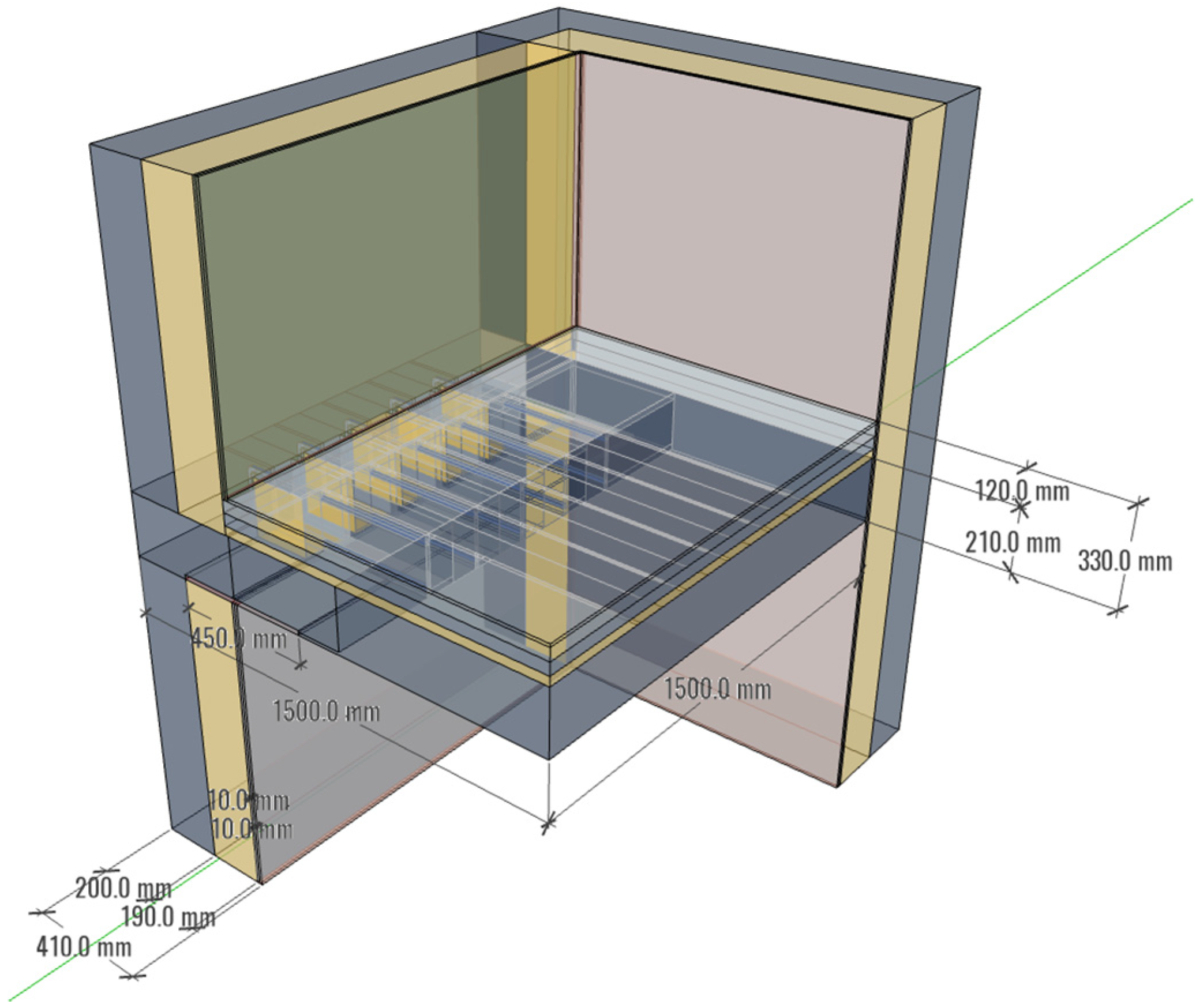
| Exterior Wall | Concrete | 200 | 1.6 |
| Insulation | 190 | 0.029 | |
| Gypsum board | 10 + 10 | 0.18 | |
| Slab | Concrete | 210 | 1.6 |
| Insulation | 30 | 0.030 | |
| Lightweight Concrete | 40 | 0.16 | |
| Mortar | 40 | 1.4 | |
| Wood flooring | 10 | 0.17 | |
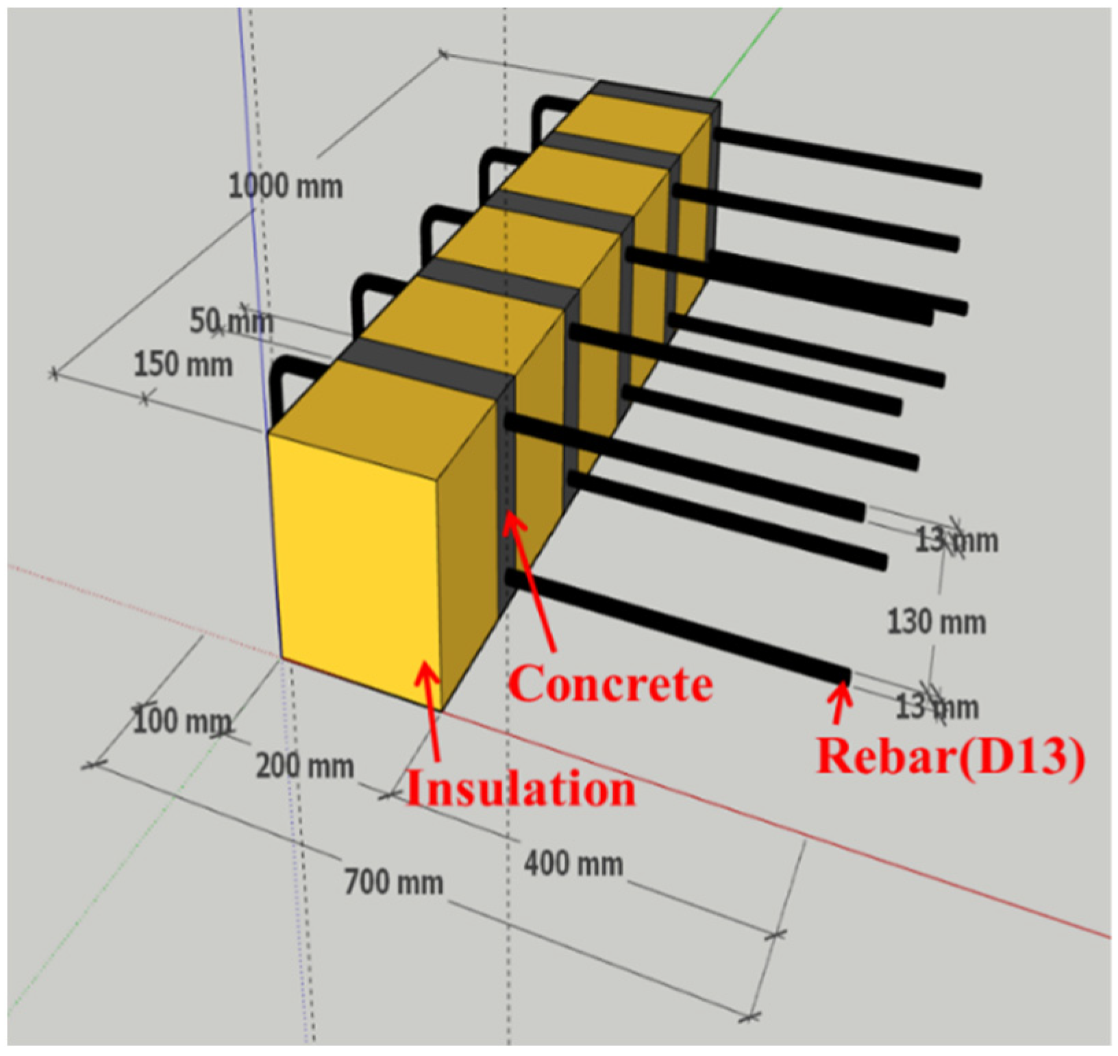
| Thermal bridge breaker | Insulation | 150 | 0.025 |
| Concrete (UHPC) | 50 | 0.2 |
| Case 1 | Case 2 | Case 3 | |
|---|---|---|---|
 |  |  | 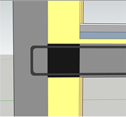 |
| Thermal bridge breaker | uninstall | uninstall | install |
| rebar | uninstall | install | install |
| Case 1 | Case 2 | Case 3 | ||
|---|---|---|---|---|
| Surface temperature [°C] | The upper part of the model | 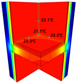 | 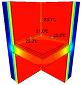 | 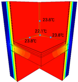 |
| The lower part of the model | 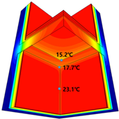 | 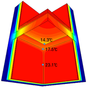 | 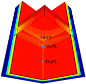 | |
| Heat loss [W/m2] | The upper part of the model | 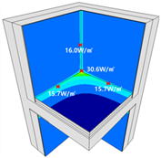 | 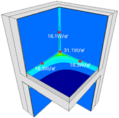 | 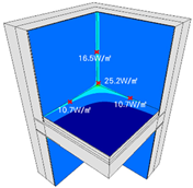 |
| The lower part of the model | 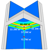 | 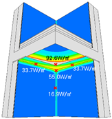 | 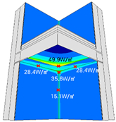 | |
| Total heat flow [W] | 61.03 | 62.88 | 45.29 | |
| Effective thermal transmittance [W/m2 K] | 0.234 | 0.241 | 0.174 | |
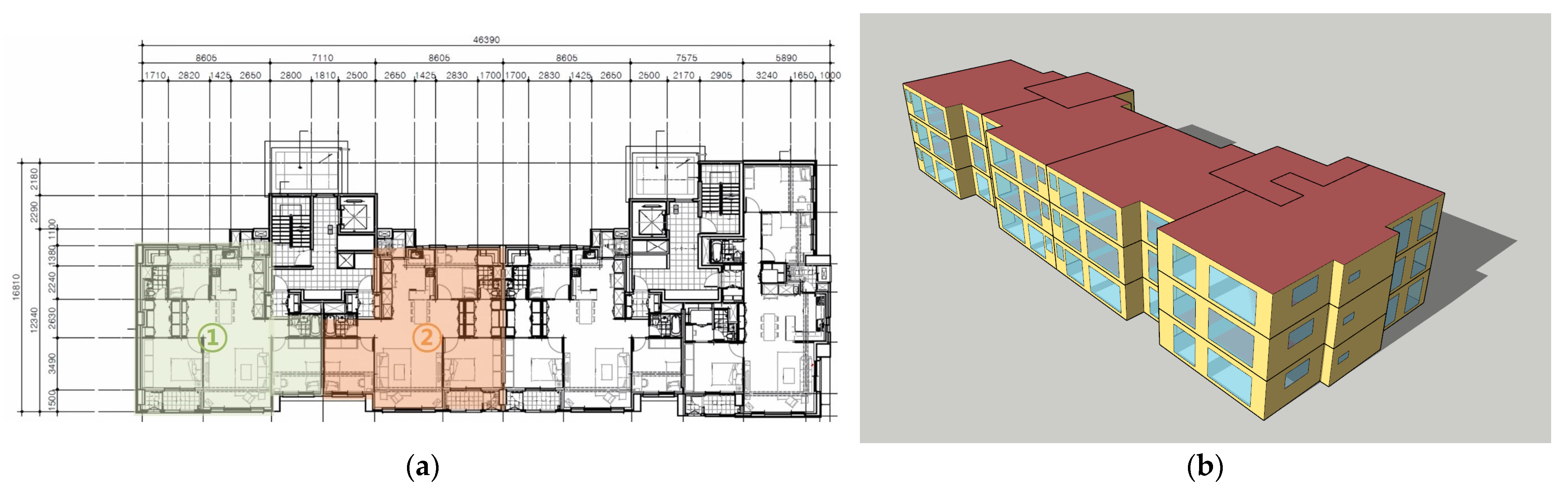
| Site Location | Seoul (Seoul weather data) |
| Design Day | −11.4 °C (21 January), 32.1 °C (21 August) |
| Setpoint Temperature | 20 °C (heating), 26 °C (cooling) |
| Thermal Transmittance | Wall 1 (0.241 W/m2 K), Wall 2 (0.174 W/m2 K), Fenestration (0.98 W/m2 K, SHGC 0.58) |
| Infiltration | 0.12 ACH (air change per hour) |
| Ventilation | 0.5 ACH |
| Schedule | Residential building schedule |
| Lighting | 3.84 W/m2 |
Publisher’s Note: MDPI stays neutral with regard to jurisdictional claims in published maps and institutional affiliations. |
© 2022 by the authors. Licensee MDPI, Basel, Switzerland. This article is an open access article distributed under the terms and conditions of the Creative Commons Attribution (CC BY) license (https://creativecommons.org/licenses/by/4.0/).
Share and Cite
Kim, M.-Y.; Kim, H.-G.; Kim, J.-S.; Hong, G. Investigation of Thermal and Energy Performance of the Thermal Bridge Breaker for Reinforced Concrete Residential Buildings. Energies 2022, 15, 2854. https://doi.org/10.3390/en15082854
Kim M-Y, Kim H-G, Kim J-S, Hong G. Investigation of Thermal and Energy Performance of the Thermal Bridge Breaker for Reinforced Concrete Residential Buildings. Energies. 2022; 15(8):2854. https://doi.org/10.3390/en15082854
Chicago/Turabian StyleKim, Mi-Yeon, Hyung-Geun Kim, Jin-Sung Kim, and Goopyo Hong. 2022. "Investigation of Thermal and Energy Performance of the Thermal Bridge Breaker for Reinforced Concrete Residential Buildings" Energies 15, no. 8: 2854. https://doi.org/10.3390/en15082854
APA StyleKim, M.-Y., Kim, H.-G., Kim, J.-S., & Hong, G. (2022). Investigation of Thermal and Energy Performance of the Thermal Bridge Breaker for Reinforced Concrete Residential Buildings. Energies, 15(8), 2854. https://doi.org/10.3390/en15082854