Abstract
This research presents a highly transparent concentrator photovoltaic system with solar spectral splitting for dual land use applications. The system includes a freeform lens array and a planar waveguide. Sunlight is first concentrated by the lens array and then reaches a flat waveguide. The dichroic mirror with coated prisms is located at each focused area at the bottom of a planar waveguide to split the sunlight spectrum into two spectral bands. The red and blue light, in which photosynthesis occurs at its maximum, passes through the dichroic mirror and is used for agriculture. The remaining spectrums are reflected at the dichroic mirror with coated prisms and collected by the long solar cell attached at one end of the planar waveguide by total internal reflection. Meanwhile, most of the diffused sunlight is transmitted through the system to the ground for agriculture. The system was designed using the commercial optic simulation software LightTools™ (Synopsys Inc., Mountain View, CA, USA). The results show that the proposed system with 200 concentration can achieve optical efficiency above 82.1% for the transmission of blue and red light, 94.5% for diffused sunlight, which is used for agricultural, and 81.5% optical efficiency for planar waveguides used for power generation. This system is suitable for both high Direct Normal Irradiance (DNI) and low DNI areas to provide light for agriculture and electricity generation at the same time on the same land with high efficiency.
1. Introduction
Solar energy is a popular alternative energy source because it does not release CO2 and is almost limitless. However, because the power density of solar energy is lower than that of nuclear power and fossil fuels (e.g., solar energy produces about 6.7 W/, while the South Texas Project nuclear power plant, including the entire 19 square-mile tract upon which the project is sited, produces about 56 W/[1]), extremely large installation areas are essential for increasing the amount of power generated by photovoltaics (PVs). Solar energy is also critical in agricultural production [2], as all crops and animals require sunlight for growth and development. However, the use of sunlight in agriculture is ineffective because plants only need a certain amount of sunlight for their growth. Typically, only one solar energy application will be installed in any land area. Solar farms, for example, often cannot grow crops due to the shade effect. Some studies have indicated that when compared to adjacent land without shade, areas below photovoltaic (PV) cell arrays receive 92% lower photosynthetic active radiation and develop only a quarter of the biomass [3]. As solar farms continue to grow significantly, land occupation intended for solar farms will intensify competition for land resources between clean energy and food production. Agrivoltaic systems are a promising solution to this problem. In particular, the process of using land for both solar power generation and agriculture, termed agrivoltaic, is witnessing rapid development throughout the world [4]. In this case, the PV panels are placed at the top of the agricultural land so that power generation and farming occur simultaneously. Due to the typical solar panel with silicon (Si) cells not being transparent, the sunlight transmitted through a solar panel to the cultivated area is inversely proportional to the panel area. If the ratio of the solar panel installation area is too large, the crop yield will be reduced tremendously. If the ratio is too small, the amount of electricity generated will be low. Thus, one must ensure a balance between sunlight for power generation and agriculture.
Many efforts have been made to develop advanced agrivoltaic systems. For example, Sekiyama et al. [5] performed experiments on optimizing the distance between solar panels to achieve the best performance of agrivoltaic systems. The study showed that with low-density solar panels, a panel distance of 1.7 m (the size of the PV modules is 1354 mm × 345 mm) can provide enough light for corn cultivation. The comparison also showed that plants grown under the system have higher yields than trees that are not shielded, although there was not much difference. However, the low density also reduces the amount of electricity produced. Sato and Yamada [6] designed and tested two types of highly transparent concentrator photovoltaic (CPV) modules for dual land use applications. The authors’ system removed traditional PV cells’ shade effect; however, the system is not suitable for locations with insufficient annual diffused sunlight for plant growth. Liu et al. [7] researched solar spectrum-splitting techniques and introduced an agrivoltaic system that uses a parabolic concentrator with a filter coating. The parabolic mirror transmits the red and blue regions of sunlight that is essential for plant growth, while simultaneously concentrating the remaining sunlight onto PV panels for power generation. However, the system uses a large area of multi-layer polymer dichroitic films to fabricate a sunlight-focused parabolic, which increases production costs. Furthermore, when using parabola dichroitic films with the solar spectrum, it is difficult to control the transmission spectral regions, as the angle of incident varies with the curvature of the parabola.
Our goal is to introduce a new structure for a highly transparent CPV system with solar spectral-splitting for dual land use applications. This structure will reduce the shade effect on plants and lower fabrication costs by utilizing the waveguide mechanism shown in Figure 1.
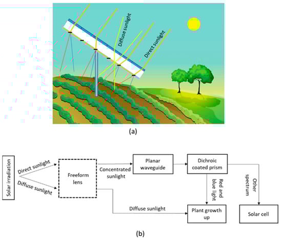
Figure 1.
(a) Concept of our proposed system with solar spectral splitting for dual land use application; (b) Block diagram of the system.
This system is almost transparent with diffused sunlight and adds the blue and red lights’ spectrum of direct sunlight for better plant growth. The remaining spectrums of direct sunlight are collected by the multi-junction solar cell. The details of the proposed design are described in Section 2.
2. System Concept
The main objective of our proposed system is to divide direct sunlight into two spectrums’ region for simultaneous power generation and farming. The system is equipped with a sun tracker to collect direct sunlight. As shown in Figure 2, our proposed system consists of two parts: a freeform lens array to focus direct sunlight and a flat waveguide with multi-junction solar cells at the end of one edge. The details of the optical system are explained below.
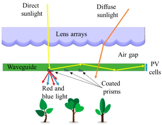
Figure 2.
The basic principles of the CPV system for dual land use application.
Sunlight is composed of two components: direct and diffuse radiations. Direct radiation has a definite direction and can be concentrated by freeform lenses. However, diffuse radiation follows a much more scattered, uncertain path. Thus, it is difficult to concentrate diffused light due to a wide range of incidence angles. To exploit diffused sunlight characteristics, we propose a highly transparent CPV system for dual land use applications. In this structure, direct sunlight is collected by the freeform lens array and focused on redirecting structures at the bottom of the flat waveguide. The redirecting structures are dichroic coated prisms. After focusing on the surface of the prisms, the concentrated beam is divided into two spectrum regions by the dichroic mirror. Due to plants requiring light in the red (620–660 nm) and blue (430–470 nm) regions [8] for growth and development, the system is designed to transmit red and blue light to the crop under the system for the plants, while the remaining spectrums are reflected at the prism surface and propagate inside the flat waveguide by total internal reflection (TIR) at the boundaries. The three edges of the waveguide are mirror coated except for one edge for solar cell attachment. The concentrated light is used to generate electricity with high efficiency, while the diffused sunlight and red and blue regions of the direct sunlight that penetrate the waveguide are provided for the plant at the same time; thus, the shade on the field can be reduced significantly. The plants under our proposed system can grow even better than the ones under the traditional agriculture photovoltaic system.
2.1. Freeform Lens Array
In a conventional CPV system, the primary concentrator is usually made by a spherical lens, Fresnel lens, or reflective parabolic mirrors; the goal of our system is to make a high transparent module for dual land use application, so we use freeform lenses for the primary concentrator because the area of the single lens is small and it is not necessary to use a Fresnel lens to reduce the thickness. Furthermore, it can achieve high precision, improving concentration ratio more than aspherical lenses since spherical aberrations are eliminated. The main characteristics of the freeform lens are shown in Figure 3, and this lens is composed of one convex surface and one flat surface. We considered that the direct sunlight was focused by the freeform lens at a focal point (F), meaning that all the rays travelling through the lens to a focal point have equal optical path length (OPL), which can be given by the equation:
where and are the refractive indices of air and the freeform lens material, respectively; and are the geometrical distances that the i-th ray travels in air and in the lens, respectively, is the optical path length of the i-th ray.
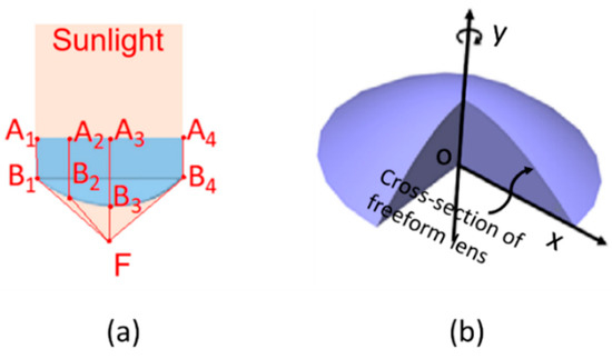
Figure 3.
(a) Design of freeform lens based on optical path length; (b) 3D structure of freeform lens made by revolving y-axis of curve surface.
We assume that the direct sunlight is a collimated beam and normal to the flat surface of the freeform lens. As all the sunrays will be focused at F, Equation (1) can be written according to the following Equation (2) with the parameters shown in Figure 3a:
where are the optical path length of the i-th ray travel in the lens and are the optical path length of the i-th ray come from convex surface to the focal point (F).
We calculated mathematically Equation (2) for the 2D coordinates of the freeform lens with a focal length of 170 mm and a lens radius of 7.1 mm. After calculating the cross-sectional of the lens, we must revolve around the revolving y-axis to obtain a freeform lens surface, as shown in Figure 3b.
We analyzed the optical distribution of the solar irradiance with the full range of the solar spectrum (400–2200 nm) after passing through the freeform lens array using the LightTools™ software. Figure 4 illustrates the distribution of the sunlight on a focal plane after being focused on by a freeform lens array. The primary concentrator is a 10 × 10 array of freeform lenses. The simulation showed that the focused area has a diameter of 0.5 mm for the single wavelength of 550 nm but was extended to 2 mm for the full range of the solar spectrum. The expansion of the focused area can be explained by chromatic aberration; thus, the lens refracts different wavelengths in sunlight at different angles.
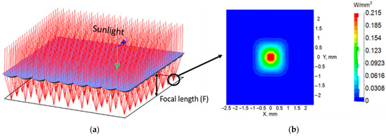
Figure 4.
(a) Sunlight is concentrated by freeform lens array; (b) The distribution on the focal plane of the concentrated Sunlight.
2.2. Flat Waveguides
The freeform lens array collects the direct sunlight and focuses it on the coated prism at the bottom of the flat waveguide. Figure 5 illustrates the mechanism of coupling sunlight into the waveguide. Only the red and blue light of the solar spectrum is transmitted for agriculture; the remaining spectrums are reflected and coupled to the waveguide by TIR to the PV cell placed at one side of the waveguide edge. This method reduces the number of PV cells and allows one heat sink to manage the entire system output.
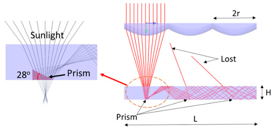
Figure 5.
The structure of the waveguide with the coated prisms.
As the diameter of the concentrated sunlight in the focal plane was 2 mm for the full spectrum of solar irradiance, the top surface of the prisms must be large enough to cover it. We determined the minimum size of the prisms was 3 mm × 3 mm by using ray-tracing. The prism angle must be calculated to satisfy the TIR condition of sunlight in the waveguide. This angle can be calculated using Snell’s law, because the angle of the concentrated sunlight is 32.6°. After refraction at the waveguide surface, this beam angle is reduced to 21.8°. The critical angle of the TIR condition for the waveguide with a refractive index of 1.49 is 41.8°; thus, we find that the prism angle is 28°, which can satisfy the given conditions.
To calculate the thickness of the waveguide, we used the theoretical analysis proposed by Karp et al. [9] for material attenuation and decoupling loss. By applying Karp’s theory, the optical efficiencies for the planar waveguide can be calculated by combining the following equations:
where is the decoupling losses; is the material attenuation; is the total optical efficiency of the waveguide; P is the distance from the exit port to each prism; H is the waveguide thickness; is the angle of the ray inside the waveguide; α is the absorption coefficient; is the concentration ratios of the freeform lens on the waveguides, and F is the F-number.
When all parameters, such as the size of the system, the size of the prisms, and the materials, were fixed, the optical efficiency of the waveguide was based on the thickness of the waveguide. In this study, we used a calculation and simulation to confirm the thickness of the waveguide when the optical efficiency was not less than 80%, and the results will be presented in Section 3.
2.3. Dichroic Mirror Designs
The dichroic mirror is coated on the prism so that blue and red light can pass through the module to the plant. To design the dichroic mirror, the most important thing is to know how much light the plant needs to grow, and based on that, to make a suitable design. Liu et al. [7] showed that a filter designed with a transmission peak width of 40 nm for blue and red light is enough for plants to grow efficiently. In this research, the dichroic mirror is designed as a Fabry-Perot resonator (FPR) [10] as shown in Figure 6, with a transparent wavelength of 470 nm and 630 nm, and the widths of the transmission peaks are 40–60 nm. The specific results are presented below.
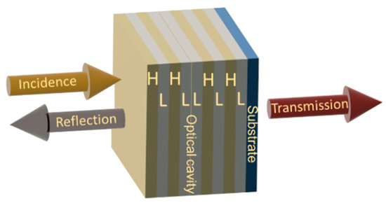
Figure 6.
Schematics of dichroic mirror made by high (H) and low (L) index layers with Fabry-Perot resonator structure.
The dichroic mirror is designed based on a narrow-band transmission filter, we assume that the filter at the design wavelength with the multilayer structure is (HL)NL(HL)N, where H and L are the high and low index layers with equal optical thicknesses, and N is the number of repeated structures (HL). With a single (HL)N structure, the high and low index layers have optical thicknesses that are quarter-wavelength layers (). When and are a refractive index of high and low index layers, respectively, and are the thickness of the high and low index layers, respectively. In this case, the (HL)N structure is regarded as a dielectric mirror with the wavelength [11]. The solutions for the left and right band edges and the bandwidth in are:
When and are the left and right band edges in , is the reflection coefficient and can be defined as follows:
A dichroic mirror structure is designed by duplicating (HL)N to (HL)N(HL)N and then a quarter wave layer L was inserted between the two groups. The resulting (HL)NL(HL)N is an FPR, and this structure opens a transmission wavelenght at , in the middle of its reflecting band . In this research, the designed dichroic mirror had a / (HL) coating with two FPRs designed for wavelengths at 470 and 630 nm, and the refractive index of the substrates and the H and L layers were: = 1.49, = 1.4 and = 2.1, , respectively. By using Equations (7) and (8), the parameters of the dichroic mirror could be calculated, and the results were and Thus, when combining two FPRs, the width of the reflected spectrum is 313 nm from 409 nm to 730 nm. After designing, we simulated a thin film structure with a different number of layers, and Figure 7a shows the response for the cases of N = 4, 8, and 10 bilayers. The results show that the simulation is consistent with the previous calculations and that the design is optimized with N = 4. We evaluated the performance of the dichroic mirror using the LightTools™ software. Figure 7b shows the performance of the dichroic mirror designed with N = 4 with different incidence angles from 0° to 40°. When the incident angle changes from 0° to 40°, the peak of the transmitted spectrum is shifted toward the smaller wavelength. Specifically, the blue light will change from 470 nm to 430 nm, and the red light will change from 650 nm to 600 nm, with an efficiency of 97% with blue light and over 86% with red light.
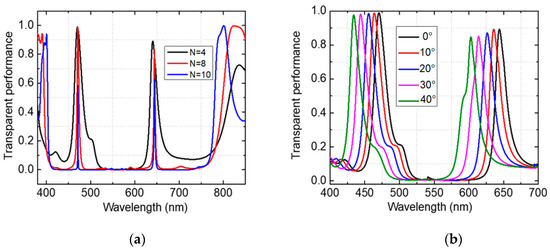
Figure 7.
Simulation results of transmission spectrum on dichroic mirror for sunlight: (a) The response for the cases of N = 4, 8, and 10 bilayers; (b) Solar spectrum-splitting with different angles of incident.
As the filter requires a wider blocking band for the entire solar spectrum, we incorporated quarter-wave interference stacks into an FPR to achieve additional blocking. Figure 8 shows that the dichroic mirror designed was a 68-layer / coating with a transparent wavelength at 470 nm and 630 nm, and additional blocking from 200–2100 nm.
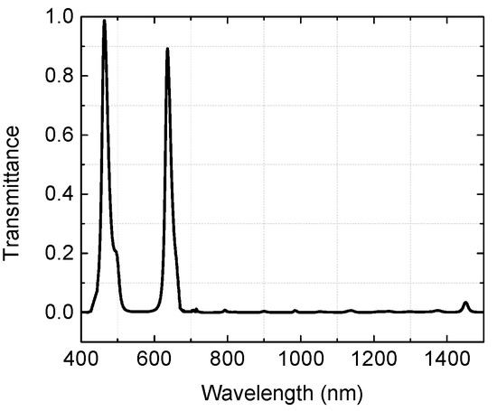
Figure 8.
Simulation results of transmittance spectral with additional blocking from 200 nm to 2100 nm.
3. System Design and Simulation Results
3.1. System Design
Our system consists of one or more split-spectrum CPV modules and is linked to the sun tracking system as shown in Figure 9. Each module consists of a lens array of size combined with a planar waveguide, and a multi-junction solar cell. InGaP/InGaAs/Ge is installed on one edge of the planar waveguide. The system’s thickness is 18 cm, and the system is fixed by an aluminum frame, which also acts as a heat sink for the solar cells. The freeform lens array and the flat waveguide are made of polymethyl methacrylate (PMMA), with a refractive index of 1.49, and the edges of the planar waveguide are mirrored except for the edge connected to the solar cell. The coated prisms in the waveguide should be made from glass because their surfaces have to work with high-intensity focused sunlight [12]. A matching gel fills the gap between the waveguide and prism, with an index of 1.51.
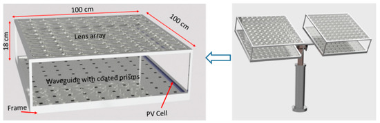
Figure 9.
Structure of our proposed spectral-splitting CPV system.
For a CPV system using waveguides, increasing the system’s length will increase the concentration ratio. Still, the decoupling loss and material attenuation become more significant, leading to a reduction in the system’s efficiency [13]. That is why we chose the system length as 1 m; moreover, this size is also easy to compare with previously tested CPV systems [6]. After choosing the length of the flat waveguide, all parameters, such as the freeform lens array, the size of the prisms, and the length of the system, were fixed. Thus, according to the optical efficiency Equations (3)–(6), is a function of the waveguide thickness. Therefore, increasing the waveguide thickness will reduce the decoupling loss but decrease the concentration ratio. Thus, we selected the thicknesses of the waveguides to be 5 mm to ensure optical efficiency above 80%, based on the simulation. With the above configuration, the system achieved a geometrical concentration ratio. Table 1 shows the specifications and structures of the module.

Table 1.
Main parameters of our proposed system.
3.2. Simulation Results
We used the LightTools™ software to simulate our proposed CPV system for dual land use application. In the simulation model, the light source with full solar spectrum from 200–2200 nm was inserted as the source. Figure 10 illustrates the simulation configuration of our design. The loss mechanism inside the waveguide is explained by some representative rays. The optical performance of our proposed system was simulated under the full solar spectrum on a real scale.
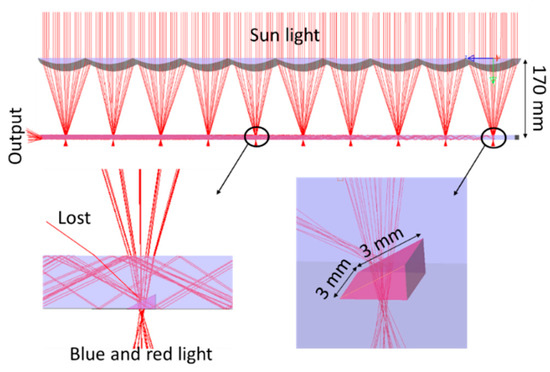
Figure 10.
The simulation structure of our proposed CPV system for dual land use.
There are two optical efficiencies for this system: the transparent efficiency and the optical efficiency of the waveguide. The transparent efficiency is the efficiency of the dichroic filter and the transparent efficiency of diffused sunlight. There was 91.3% efficiency with blue light (430 nm–470 nm), 82.1% with red light (600 nm–650 nm), and 94.5% with diffused sunlight, including Fresnel loss and material absorption. The efficiency was calculated by dividing the transmitted energy integral by the total incoming energy integral for the corresponding spectral regions.
The optical efficiency of the waveguide is the ratio of the output power at the end of the waveguide to the input power. It depends on many factors, including Fresnel losses occurring at the boundary between two transparent media, absorption of the material, transmission or reflection losses in the dichroic mirror, and decoupling loss of the waveguide. We evaluated the optical efficiency of the waveguide by simulating the waveguide with different thicknesses. The results are shown in Figure 11. The optical efficiency of the waveguide is 81.3%, and the concentration ratio is 200× when the waveguide thickness is 5 mm.
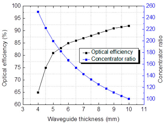
Figure 11.
The dependence of optical efficiency on waveguide thickness.
As our system has a high concentration ratio and requires a sun tracking system, hence in this study, we simulated the system’s acceptance angle. The acceptance angle is defined as the incidence angle at which the optical efficiency decreases to 10% from the maximum value [14], The incident angle is simulated along the x- and y-axes and is shown in Figure 12a. The dependence of the optical efficiency on incident angle is shown in Figure 12b. It shows the asymmetric distribution of the acceptance angle along the y-axis; the reason is that the angle of inclination of the prism is placed along the y-axis so the influence of the angle of incidence will be different. The acceptance angle value is ±; with such an angle of acceptance, our system is suitable for most commercial dual-axis solar tracker systems [15].
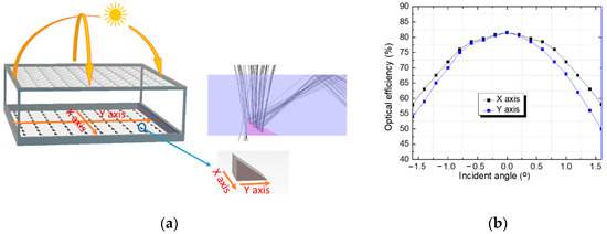
Figure 12.
Optical efficiency according to incident angle along x and y-axes: (a) Raytracing at incidence angle of + along y-axis; (b) Optical efficiency depending on deviation of sunlight beam.
We also simulated the transmission and reflection bands at the output of the planar waveguide to evaluate the efficiency of the dichroic mirror, as shown in Figure 13. The simulation results showed that the filter had transmittance over 80% for blue and red light when applied to the system. The transmittance spectral region is extended by more than 100 nm and tends to deviate towards the low wavelength region due to the diversity of the incident angle of the focused sunlight hitting the surface of the prism.
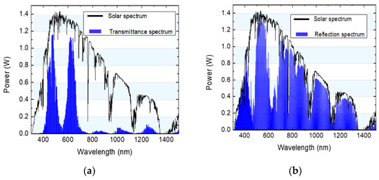
Figure 13.
The performance of the dichroic mirror: (a) Transmittance spectrum; (b) Spectrum at the output of the planar waveguide.
4. System Performance and Discussion
4.1. Solar Energy for Growing Plants
To calculate the efficiency of the system on plants, we will consider plant light requirements, which are usually defined by the daily light integral (DLI) or the total amount of photosynthetically active radiation (PAR) that falls on the plant during the day [16], measured in moles of photons (). DLI requirements of plants are typically categorized into four types: low-light (<10 //day), moderate-light (10–20 //day), high-light (20–30 //day), and very high-light (>30 //day) [17]. PAR is the spectral range from 400 nm to 700 nm of solar radiation that plants are able to use in the process of photosynthesis, and PAR is measured as Photosynthetic Photon Flux Density (PPFD), with units in //s, in which 1 //s = 6.022 × light particles (photons) hitting a area in one second. To convert the PAR obtained from the solar spectrum in , we integrally divide the photon flux spectrum in the 400–700 nm region () over the full spectrum radiation ()
where is transmission efficiency of the diffused sunlight; is the incident spectrum of photon flux, and is the spectrum in W/m2. As our system allows for using wavelengths from 420–470 nm and 600–655 nm of direct solar radiation for plants, the PAR for the direct irradiation is calculated using the following formula:
where and are the transmission efficiencies of the filter for the blue and red regions, respectively.
Using NREL’sAM1.5 reference spectra operated by the Alliance for Sustainable Energy LLC and applying Formula (9) for diffused sunlight and Equation (10) for direct sunlight, we can calculate the PAR of the system for both the direct and diffused components, which are: direct = 0.41 s−1/ and diffuse: 2.38 s−1/. Applying these conversion factors to the solar irradiance data for Seoul (Korea) in January and August, we calculated the DLI obtained from the solar irradiance on a typical clear day, as shown in Figure 14. The winter solar radiation delivers a sufficient DLI for moderate-light crops, while a summer day in Seoul delivers a DLI for high-light crops.
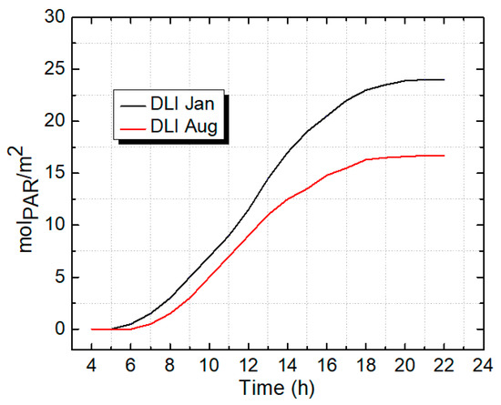
Figure 14.
DLI along a day in January and August for Seoul (Korea).
4.2. Electricity Generation
We calculated the amount of electricity generated by our proposed system on a typical sunny day with direct sunlight of 800 W/m2 and a sunny time of 10 h. The InGaP/InGaAs/Ge three-junction solar cell used for this system has a conversion efficiency of 35% [18]. The power conversion efficiency of the proposed system can be calculated using the equation:
Figure 15 shows the power generation for one module with a size of 1 m × 1 m. The total energy can be calculated by taking the integral of the output power over the day, which is 2.84 kWh.
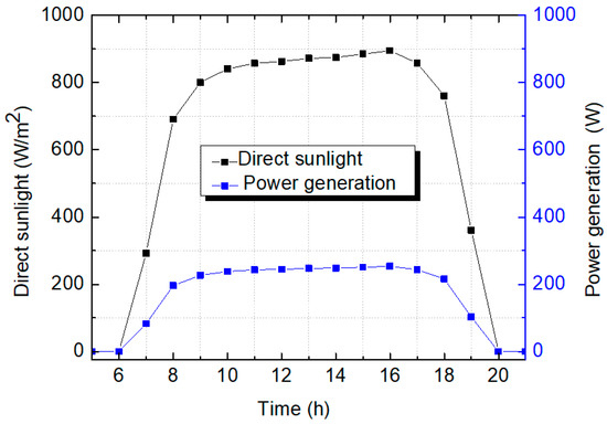
Figure 15.
Power generation of one CPV module over a summer day.
To evaluate the effectiveness of our system in dual land use, we conducted a performance evaluation of our proposed system compared to transparent CPV and 30% transparent PV, as shown in Figure 16. The transparent CPV [6] uses a PMMA Fresnel lens array (10 × 10) with a geometrical concentration ratio of 100×, three-junction solar cells with 35% efficiency for electric generation, and diffused sunlight transmitted through the module for agriculture. The 30% transparent PV module [19] is a PV panel with a 70% density of monocrystalline silicon solar cells, and the solar cell efficiency is 18%.
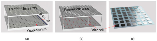
Figure 16.
Comparison setup: (a) Our proposed system; (b) High transparent CPV, and (c) 30% transparent PV.
The comparison was made under the same climates as 1000 W/ with different diffused sunlight ratios. We assumed that the sizes of both systems were the same as our proposed module, which is 1 m 1 m. Table 2 shows the energy generation and the DLI of each system collected per day. Both CPV systems generate electricity efficiently under conditions of high direct sunlight, and the generated electrical energy is 2–2.5 times higher than a transparent PV system. However, an ordinary transparent CPV system will not provide enough light needed for high-light plants in areas with high direct sunlight, while our system is fully responsive for high-light plants. This suggests that our proposed system has more advantages in dual land use, particularly in areas with high direct sunlight.
Table 2.
Comparison in performance between 30% transparent PV system, transparent CPV, and our proposed system.
5. Conclusions
In this paper, we have presented the new highly transparent CPV system with spectral splitting. The design concept allows to produce electricity and cultivate the crops in the same area. Optical efficiency, concentration ratio, and system performances were evaluated using LightTools™ software, with a current transmittance spectral range of the dichroic mirror of 430–470 nm and 600–650 nm, and concentrator ratio is 200×. Although this system delivers a slightly reduced electricity generation due to the lack of red and blue light, which are transmitted to support plant growth, it can generate more electricity by being able to cover larger areas of farmland without affecting the growth of the plant by shading, in comparison with traditional flat PV systems. Moreover, the proposed system can work in different climates with different DNI and still provide enough light for high-light plants to grow up. In the near future, we will conduct experiments to verify the simulations and evaluate the possibility of commercialization.
Author Contributions
Original idea conceptualization, H.V.; Simulation, H.V., T.Q.T., J.P. and N.H.V.; formal analysis, N.H.V.; writing—original draft preparation, H.V. and M.C.; review and editing, N.H.V. and S.S.; project administration, S.S. All authors have read and agreed to the published version of the manuscript.
Funding
This work was supported by the National Research Foundation of Korea (NRF) grant funded by the Korea government (MSIT) (project number: 2021R1A2C1010879). This work was also supported by Korea Energy Agency (project number: 20012625) and Vietnam National Foundation for Science and Technology Development (NAFOSTED) under grant number NCUD.01-2019.13.
Institutional Review Board Statement
Not applicable.
Informed Consent Statement
Not applicable.
Data Availability Statement
The data that support the findings of this study are available on request from the first author.
Conflicts of Interest
The authors declare no conflict of interest.
References
- Layton, B.E. A comparison of energy densities of prevalent energy sources in units of joules per cubic meter. Int. J. Green Energy 2008, 5, 438–455. [Google Scholar] [CrossRef]
- Vu, T.N.; Tran, Q.T.; Tong, Q.C.; Nguyen, M.H.; Kieu, N.M.; Vu, N.H.; Vu, H.; Seoyong, S. Development of a solar/LED lighting system for a plant tissue culture room. J. Vietnamese Environ. 2020, 12, 142–147. [Google Scholar] [CrossRef]
- Armstrong, A.; Ostle, N.J.; Whitaker, J. Solar Park microclimate and vegetation management effects on grassland carbon cycling. Environ. Res. Lett. 2016, 11, 074016. [Google Scholar] [CrossRef] [Green Version]
- Santra, P.; Pande, P.C.; Kumar, S.; Mishra, D.; Singh, R.K. Agri-voltaics or solar farming: The concept of integrating solar PV based electricity generation and crop production in a single land use system. Int. J. Renew. Energy Res. 2017, 7, 694–699. [Google Scholar]
- Sekiyama, T.; Nagashima, A. Solar sharing for both food and clean energy production: Performance of agrivoltaic systems for corn, a typical shade-intolerant crop. Environments 2019, 6, 65. [Google Scholar] [CrossRef] [Green Version]
- Sato, D.; Yamada, N. Design and testing of highly transparent concentrator photovoltaic modules for efficient dual-land-use applications. Energy Sci. Eng. 2020, 8, 779–788. [Google Scholar] [CrossRef]
- Liu, W.; Liu, L.; Guan, C.; Zhang, F.; Li, M.; Lv, H.; Yao, P.; Ingenhoff, J. A novel agricultural photovoltaic system based on solar spectrum separation. Sol. Energy 2018, 162, 84–94. [Google Scholar] [CrossRef]
- Chory, J.; Chatterjee, M.; Cook, R.K.; Elich, T.; Fankhauser, C.; Li, J.; Nagpal, P.; Neff, M.; Pepper, A.; Poole, D.; et al. From seed germination to flowering, light controls plant development via the pigment phytochrome. Proc. Natl. Acad. Sci. USA 1996, 93, 12066–12071. [Google Scholar] [CrossRef] [PubMed] [Green Version]
- Pisani, G. Correzione Delle Deformita Del Piede Post-Allungamento. Chir. Piede 1994, 18, 235–240. [Google Scholar] [CrossRef]
- Belyaev, B.A.; Tyurnev, V.V.; Shabanov, V.F. Design of optical bandpass filters based on a two-material multilayer structure. Opt. Lett. 2014, 39, 3512. [Google Scholar] [CrossRef] [PubMed]
- Orfanidis, S.J. Electromagnetic Waves and Antennas; Rutgers University: New Brunswick, NJ, USA, 2016; Volume 6, pp. 335–370. [Google Scholar]
- Vu, N.H.; Pham, T.T.; Shin, S. Large scale spectral splitting concentrator photovoltaic system based on double flat waveguides. Energies 2020, 13, 2360. [Google Scholar] [CrossRef]
- Vu, N.H.; Shin, S. A large scale daylighting system based on a stepped thickness waveguide. Energies 2016, 9, 71. [Google Scholar] [CrossRef] [Green Version]
- Pérez-Higueras, P.; Ferrer-Rodríguez, J.P.; Almonacid, F.; Fernández, E.F. Efficiency and acceptance angle of High Concentrator Photovoltaic modules: Current status and indoor measurements. Renew. Sustain. Energy Rev. 2018, 94, 143–153. [Google Scholar] [CrossRef]
- Sun Tracking System. Available online: http://www.solar-motors.com/gb/solar-trackers/dual-axis-sun-trackers-g78.shtml (accessed on 4 June 2021).
- Apostoleris, H.; Chiesa, M. High-concentration photovoltaics for dual-use with agriculture. AIP Conf. Proc. 2019, 2149, 050002. [Google Scholar] [CrossRef]
- Song, X.P.; Tan, H.T.W.; Tan, P.Y. Assessment of light adequacy for vertical farming in a tropical city. Urban For. Urban Green. 2018, 29, 49–57. [Google Scholar] [CrossRef]
- Sabnis, V.; Yuen, H.; Wiemer, M. High-efficiency multijunction solar cells employing dilute nitrides. AIP Conf. Proc. 2012, 1477, 14–19. [Google Scholar] [CrossRef] [Green Version]
- Tranparent Solar Panel. Available online: https://www.ertex-solar.at/en/products/semi-transparent-modules/ (accessed on 24 November 2021).
Publisher’s Note: MDPI stays neutral with regard to jurisdictional claims in published maps and institutional affiliations. |
© 2022 by the authors. Licensee MDPI, Basel, Switzerland. This article is an open access article distributed under the terms and conditions of the Creative Commons Attribution (CC BY) license (https://creativecommons.org/licenses/by/4.0/).