Article

Numerical Simulations on the Application of a Closed-Loop Lake Water Heat Pump System in the Lake Soyang, Korea

Korea Institute of Geoscience and Mineral Resources, Daejeon 34142, Korea
*
Author to whom correspondence should be addressed.
Energies 2020, 13(3), 762; https://doi.org/10.3390/en13030762
Submission received: 13 January 2020 / Revised: 6 February 2020 / Accepted: 6 February 2020 / Published: 9 February 2020
(This article belongs to the Section H: Geo-Energy)

Abstract

:
A lake is one of the geothermal energy sources to meet increasing demands for renewable energy use. In this study, a series of numerical modeling was performed to evaluate the applicability of a close-loop lake water heat pump (LWHP) system in Lake Soyang, Korea. A non-isothermal pipe flow model was used to simulate the flow and heat transfer processes occurring in the LWHP system with the main pipe and several helical tubes for heat exchange. Based on the temperature data measured in the Lake Soyang for 4 years, the installation depth and the number of helical tubes were determined sequentially, and the sensitivities of additional installation and operation factors on the system performance were analyzed. Assuming a mild current in the lake, the installation and operation conditions for the efficient operation of the system were suggested as follows: The installation of 16 helical tubes at 50 m deep, the circulation rates of heat-carrier fluid of 189.3 L/min, the inner diameter of tubes of 32 mm, and the wall thickness and thermal conductivity of 2.9 mm and 0.4 W/mK, respectively. Considering many lakes and reservoirs in Korea, the closed-loop LWHP system would be a viable renewable energy application.

1. Introduction

Among several types of geothermal energy applications, a lake-based geothermal cooling, and heating system, called the lake water heat pump (LWHP) system, has more advantages in terms of energy-efficiency, ease of installation, and cost comparing to a ground source cooling and heating system [1]. Considering the high specific heat capacity of water, particularly, lakes must be a competent heat source and sink for heating and cooling. The LWHP system can be operated in ways of the open-loop or the closed-loop for heat exchange with lake water. While the former directly extracts the water reserved in a lake for heat exchange and discharges the heat-exchanged water back to the lake or to a drainage system, the latter circulates a heat-carrier fluid through a piping loop heat exchanger (e.g., helical pipe) submerged in lake water [2,3,4].
Generally, the open-loop scheme of the LWHP can provide higher efficiency than the closed-loop scheme. However, it has a burden of legislative permits and costs for lake water extraction and returning and risks of freezing, corrosion, and biofouling, which can obstruct the stable operation of the system [2,3,4,5]. In particular, the discharge of water used for the operation of the open-loop system can affect the physical properties and the ecological conditions of lakes [2,5,6]. Comparing the open-loop system to the closed-loop LWHP system may have relatively low efficiency and a concern for leakage of a heat-carrier fluid due to accidental pipe failure [7]. However, the closed-loop system has little effect on the lake water; it can be applied in lakes with low water quality or high sediment content. In addition, the closed-loop system is relatively easy to achieve the performance of operation desired at a planning stage [7,8,9,10,11,12]. Above all, because the performance of the closed-loop system depends on the heat transfer efficiency of the system itself [5], it may not be necessary to characterize the dynamics of lake water in detail. If an antifreeze solution can be used as the heat-carrier fluid, the closed-loop LWHP system enables heating operation in cold climates [8].
There have been several studies about the operation of the closed-loop LWHP system. Actually, the LWHP system is a type of surface water heat pump (SWHP) system, and, therefore, most of its features and operation are similar to those of the SWHP systems using various water bodies, such as pond, lagoon, river, seawater, and even wastewater. Chiasson et al. [13] demonstrated a model to simulate the heat transfer performance of a shallow pond considered as a supplemental heat reject of the closed-loop ground source heat pump system. Büyükalaca et al. [14] investigated the potential of the Seyhan River and the dam lake as the heat source and sink for the application of the LWHP system in Turkey. Morton [3] investigated the feasibility of a reservoir as a heat source for the LWHP system application on a university building in the UK. Schibuola and Scarpa [15] showed the case study on the SWHP system using lagoon water as an alternative for space heating and cooling of a historic building in Venice, Italy, where groundwater source cooling and heating is restricted. Zheng et al. [16,17] presented numerical and experimental investigations of the thermal characteristics of a helical coil exchanger for a seawater heat pump system under icy and non-icy conditions in winter. Kuyuk et al. [18] suggested a cooling system using cold water from the hypolimnion of a deep lake for air conditioning of an underground mine in Canada. Recently, a few studies focused on a variety form of heat exchangers for an SWHP system, which was devised to improve the performance of heat exchanger, rather than the thermal characteristics of water bodies. Fernández-Seara et al. [19] developed a numerical model to predict the heat transfer process and pressure drop in two vertical helical coil heat exchangers installed in a fluid storage tank. Mitchell et al. [8] presented the natural convection heat transfer correlations for a spiral-helical type of heat exchanger through heat extraction and rejection experiments. Wu et al. [20] developed a mathematical model to evaluate the thermal performance of the double-helical heat exchanger for a seawater heat pump system. Zhou et al. [10,11,12] demonstrated a series of experimental and numerical approaches to predict and evaluate the thermal performance of the multi-row helically coiled heat exchanger with different diameters accurately.
For the LWHP systems using shallow ponds or cold deep lake water for only cooling, it may be unnecessary to consider thermal stratification significantly (e.g., [3,13,18,21]). In deep lakes, however, thermal stratification can be created in summer and winter [2,5]. The resulting temperature distribution with respect to the depth of a lake, which is heat source or sink, must be critical to the performance of the LWHP system for cooling and heating purposes. Above all, lakes have their own temperature profiles depending on local weather conditions and depth profiles of the lakes. To plan the installation and operation of an LWHP system, therefore, it is essential to monitor the long-term temperature profiles of the lake [2,6]. In practice, however, the long-term temperature measurement data in lakes are scarce and, as a result, there are few studies on the application of the LWHP system based on the long-term temperature measurement in lakes.
At present, the use of the SWHP system is limited, but it is expected to increase significantly due to the new renewable energy policy of the Korean government. To expand the renewable energy use into many lakes and reservoirs in Korea, it is necessary to suggest and develop the applications of various LWHP systems suitable to their site-specific hydrological and thermal environments. This study is to demonstrate the potential for the utilization of and to evaluate the applicability of a closed-loop LWHP system for both cooling and heating purposes. A series of numerical simulations on the installation and operation of the system was performed based on the long-term temperature measurements in a lake in Korea. For this, a non-isothermal piping flow model was introduced to describe the flow and heat transfer processes in a hypothetical closed-loop LWHP system installed at the lake.

2. The Status of the Surface Water Heat Pump System in Korea

The Korean government established the third national energy master plan in 2019. According to this new plan, the renewable energy sources of Korea will expand to 30%–35% of the entire power generation by 2040 [22]. In 2018, however, the renewable sources were still responsible for only 5.79% (17,799,383 TOE) of the total energy production, and even geothermal energy accounts for only 1.2% (205,464 TOE) of the renewable energy sources [23]. Therefore, more supply and utilization of geothermal energy should be considered and promoted increasingly in Korea in the near future.
The LWHP system can be considered for expanding renewable energy use in Korea, where there exists a total of 17,490 reservoirs for multi-purposes, domestic and industrial water supply, hydropower generation, and agricultural water supply; their effective reserving capacity of all reservoirs is estimated to be 13,708.2 Mm3 [24]. The LWHP system has commonly been studied and utilized in Canada [18], China [16,17,21,25], Italy [15], Turkey [14], UK [3,5], and USA [8,13,26], but applications of this system has hardly been attempted in Korea thus far.
In 2019, the Act on the Promotion of the Development, Use, and Diffusion of New and Renewable Energy in Korea was amended so that thermal uses of surface water including rivers and lakes can have legal ground. In addition, the Gangwon Provincial government in Korea is planning to build the world’s only cyclic lake-based geothermal energy linkage system in Soyanggang Dam, called the Soyanggang Dam Thermal Energy Convergence and Integration Cluster Construction Project. According to the plan, around 250,000 tons of cold water extracted directly from the hypolimnion of the dam reservoir, Lake Soyang, will be first used for cooling of internet data center complexes. Some of the water warmed through the cooling process will be sent to farms and villages for greenhouse agriculture, and home heating and the re-cooled water will then return to the data centers for additional cooling, while the rest will be sent to the municipal purification plant for citizens and stream restoration.

3. Materials and Methods

3.1. Lake Soyang and Its Temperature Profile

Lake Soyang is located in the city of Chuncheon, Korea, which is on the upper part of the Han River (Figure 1). It was artificially formed by the construction of the Soyanggang Dam in 1968. The total area of Lake Soyang is 960 km2, with a total storage of about 2.9 billion tons and the watershed area of 2703 km2, which is the largest reservoir in Korea. The maximum and mean depths of Lake Soyang are 118 and 61 m, respectively [27].
The temperature-depth profiles in Lake Soyang during the years from 2001 to 2004 were obtained from Figure 9 of Lee and Han [28], which had been measured at 10 m depth intervals near the Soyanggang dam (Figure 1 and Figure 2). Figure 2 shows all of the monthly measurements for the period, and the seasonal cycle of stratification generally observed at other lakes with a similar temperate climate. In the period from June to August during those years, the high air temperature and solar radiation raised the temperature of the top layer in Lake Soyang up to 21.9–28.9 °C, depending on the weather conditions. During the winter seasons, as the air temperature decreased, the epilimnion began to cool down, and its temperature decreased from the maximum of 17.3 to a minimum of 6.6 °C. The hypolimnion having a stable temperature at around 4 °C throughout the year was located deeper than the depth of 60 m, but the layer sometimes developed at around 20 m deep during the summer seasons. In turn, the location and the depth of the thermocline differed from month to month every year, which should be considered for designing a lake-based cooling and heating system.

3.2. Computational Model

A non-isothermal pipe flow model formulated in Comsol Multiphysics 5.4 was used to simulate the operation of a closed-loop LWHP system in Lake Soyang. The model solved the heat transfer equation together with the equations for compressible flow in the pipes. The flow and the temperature in the pipe system were approximated by one-dimensional curve segments or lines.

3.2.1. Flow Equation

The flow inside the pipe system can be described by the momentum and continuity equations as below,
ρ u t = p f D ρ 2 d h u | u | + F
A ρ t + · ( A ρ u ) = 0
where ρ (kg/m3) is the density, t (s) is the time, u (m/s) is the fluid velocity in the tangential direction of the pipe curve segment, p (N/m2) is the pressure, fD (–) is the Darcy friction factor, F (N/m3) is a volume force, such as gravity, and A (m2) is the cross-section area of the pipe. In addition, dh (m) is the mean hydraulic diameter as
d h = 4 A Z
where Z (m) is the wetted perimeter of the pipe.
The Darcy friction factor (fD) in Equation (1) can be obtained from the Reynolds number and the surface roughness (e) divided by the hydraulic pipe diameter (d) shown in Equations (4)–(6), which is known as the Churchill relation [29].
f D = 8 [ ( 8 Re ) 12 + ( α + β ) 3 / 2 ] 1 / 12
α = [ 2.457 ln ( ( 7 Re ) 9 / 10 + 0.27 ( e / d ) ) ] 16
β = ( 37530 Re ) 16
where Re (–) is the Reynolds number, which is a function of the fluid properties as follows,
Re = ρ u d μ

3.2.2. Heat Transfer Equation

The heat transfer for the pipe flow is given in Equation (8)
ρ A C p T t + ρ A C p u · T = · A k T + f D ρ A 2 d h | u | 3 + Q wall
where Cp (J/(kg·K)) is the specific heat, T is the temperature (K), and k (W/(m·K)) is the thermal conductivity. The second term on the right-hand side of Equation (8) corresponds to friction heat dissipated due to viscous shear. Qwall (W/m) is a heat source or sink term due to heat exchange with the surroundings through the pipe wall as
Q wall = h Z ( T ext T )
where h (W/(m2·K)) is the heat transfer coefficient, and Text (K) is the external temperature outside of the pipe. For the heat source or sink on the internal pipe wall the heat transfer coefficient can be calculated by Equation (10)
h = Nu k d h
where Nu (–) is the Nusselt number.
The Gnielinski equation [30] was used for internal turbulent forced convection in Equation (10),
Nu int = ( f D / 8 ) ( Re 1000 ) Pr 1 + 12.7 ( Pr 2 / 3 1 )
where Pr (–) is the Prandtl number as
Pr = C p μ k
In addition, the external forced convection around a pipe can be calculated by the Churchill and Bernstein relation [31] as
Nu ext = 0.3 + 0.62 Re 1 / 2 Pr 1 / 3 [ 1 + ( 0.4 / Pr ) 2 / 3 ] 1 / 4 [ 1 + ( Re / 282000 ) 5 / 8 ] 4 / 5
Re = ρ u ext d h μ
where uext (m/s) is the outside fluid velocity.
The LWHP system was assumed to consist of a closed-loop network of the main pipe and several helical tubes for heat exchange with lake water. The inlet and outlet of the main pipe were connected to the heat pump unit. Once the heat-carrier fluid inflows into the heat pump from the outlet of the main pipe, a temperature difference by heating or cooling loads will be added to the fluid after passing through the heat exchanger, which is then assigned as the inlet temperature. This process is given by
T in i = T out i 1 + Δ T
Δ T = P ρ C P q
where T in i (K) is the inlet temperature at an i-th time step, T out i 1 (K) is the outlet temperature at an (i−1)-th time step, ΔT (K) is the temperature difference, P (W) is cooling or heating loads, and q (m3/s) is the volumetric flow rate.

3.3. Model Setting and Assumptions

As a base condition, a closed-loop LWHP system was assumed to consist of the main pipe and 20 helical tubes for heat exchange with the lake water (Figure 3). Each helical tube had 10 turns with a radius of 1 m and a pitch of 30 cm. Once a heat-carrier fluid flowed from the inlet after passing through the heat exchanger of the heat pump, it was distributed to the first array of helical tubes located at the leftmost in Figure 3. The distributed heat-carrier fluid exchanged heat with surrounding lake water flowing through the respective helical tubes. Then, it flowed into the next array of helical tubes. After joining to the main pipe, the fluid outflowing from the second array was again distributed into the third arrays and thereafter flowed into the last arrays. Finally, the fluid that had exchanged heat with lake water through all helical tubes flowed toward the heat pump. The outer diameters of the pipe and tubes were 75 mm and 32 mm, respectively, to implement the reverse return method for avoiding an excessive pressure drop in the pipe. The wall thickness of the helical tubes for heat exchange with lake water was 2.9 mm; the thermal conductivity of the tube wall was 0.4 W/mK. No heat loss through the wall of the main pipe was assumed. The volumetric flow rate at the inlet of the main pipe was given to be 189.3 L/min. Due to a lack of data, the flow velocity in Lake Soyang was set to be 0.2 m/s, which represented a slow current. The cooling and heating loads for the LWHP to be installed in a building were assumed to be 50 kW, respectively. The operation periods for cooling and heating were 92 days in summer (June–August) and winter (November–January), respectively, while the system did not work in the remaining seasons. Concerning a leak accident of the heat-carrier fluid due to unexpected damage in the pipe and tubes, pure water was considered as the heat-carrier fluid.
To evaluate the performance and efficiency of the LWHP system, the relation between the coefficients of performance (COP) and temperatures of the entering fluid, defined as the outlet temperature (Tout) in this study, were obtained from the specification datasheet of a commercial heat pump, Aquarious EC150 by FHP Manufacturing Company, as shown in Figure 4. The COP-temperature relation could be used for evaluating the relative rank of various types of candidate installations and operations for a given heat pump, although it cannot evaluate the absolute feasibility of the candidates because every heat pump had its own COP-temperature relation. In Figure 4, the two equations for cooling and heating COPs were, respectively, derived by a curve fitting method using the capacity data of the heat pump. Although the temperature condition of deep lake water in summer is favorable for cooling, no capacity data of the assumed heat pump was given for the range of the entering water temperature below 10 °C. For this reason, the extrapolation for the cooling COP equation was applied to compare the performance of the LWHP system quantitatively under variable operation conditions (shown with the dashed line in Figure 4).

4. Results

4.1. Modeling Procedure

Based on the long-term temperatures measured in Lake Soyang over 4 years, a series of numerical modeling was performed to assess the effects of several installation and operation conditions on the performance of the LWHP system in the lake. It can eventually provide information on the designing parameters and the operating conditions for the LWHP system. Numerical modeling was first performed under the aforementioned base condition for determining the installation depth. The depth of the bottom of the helical tube was defined as the installation depth in this study. Thereafter, the most suitable values of parameters derived in the previous step were sequentially used as a base setting for the simulation at the next step. The installation and operation parameters and their values considered in this study are summarized in Table 1.

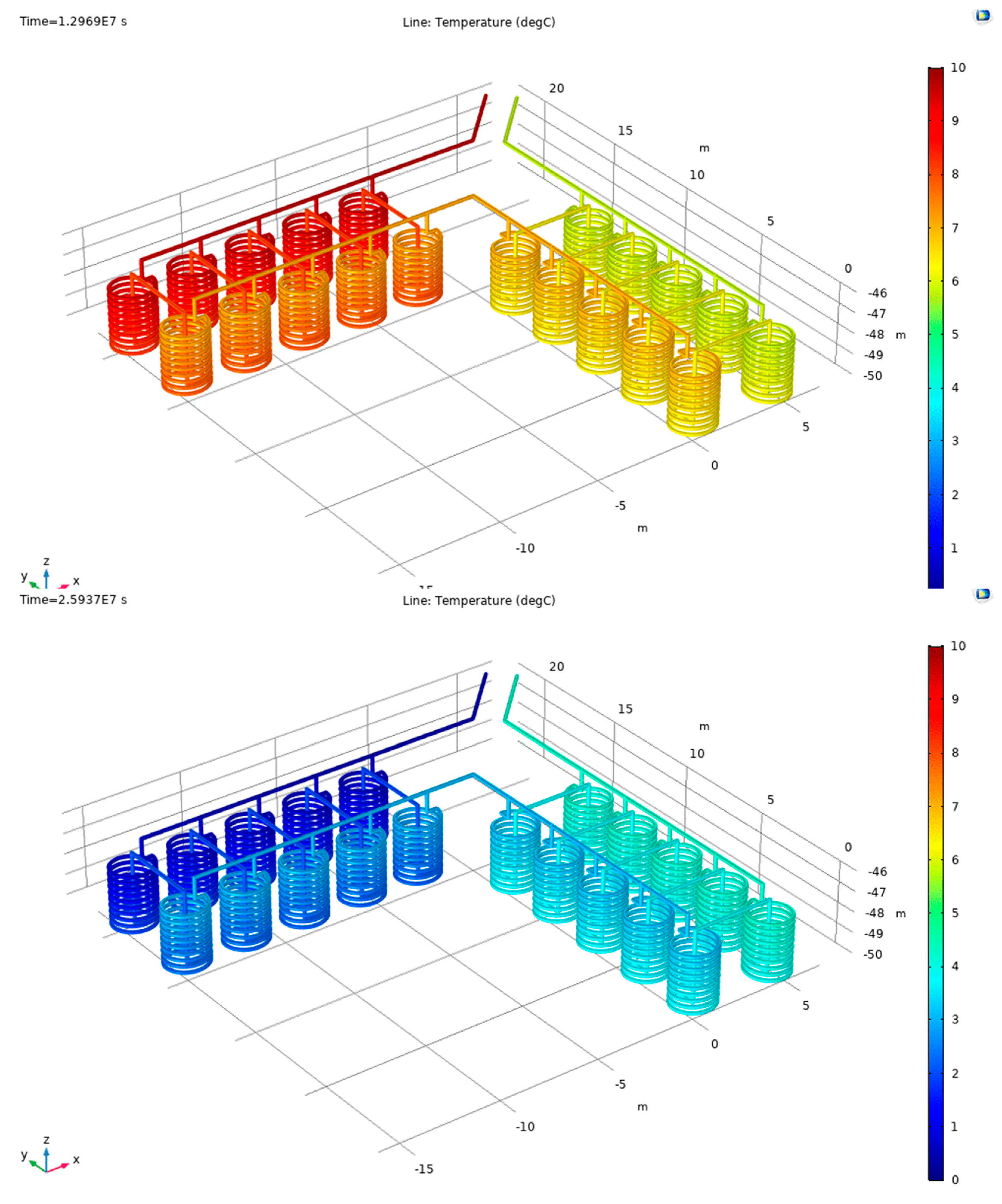
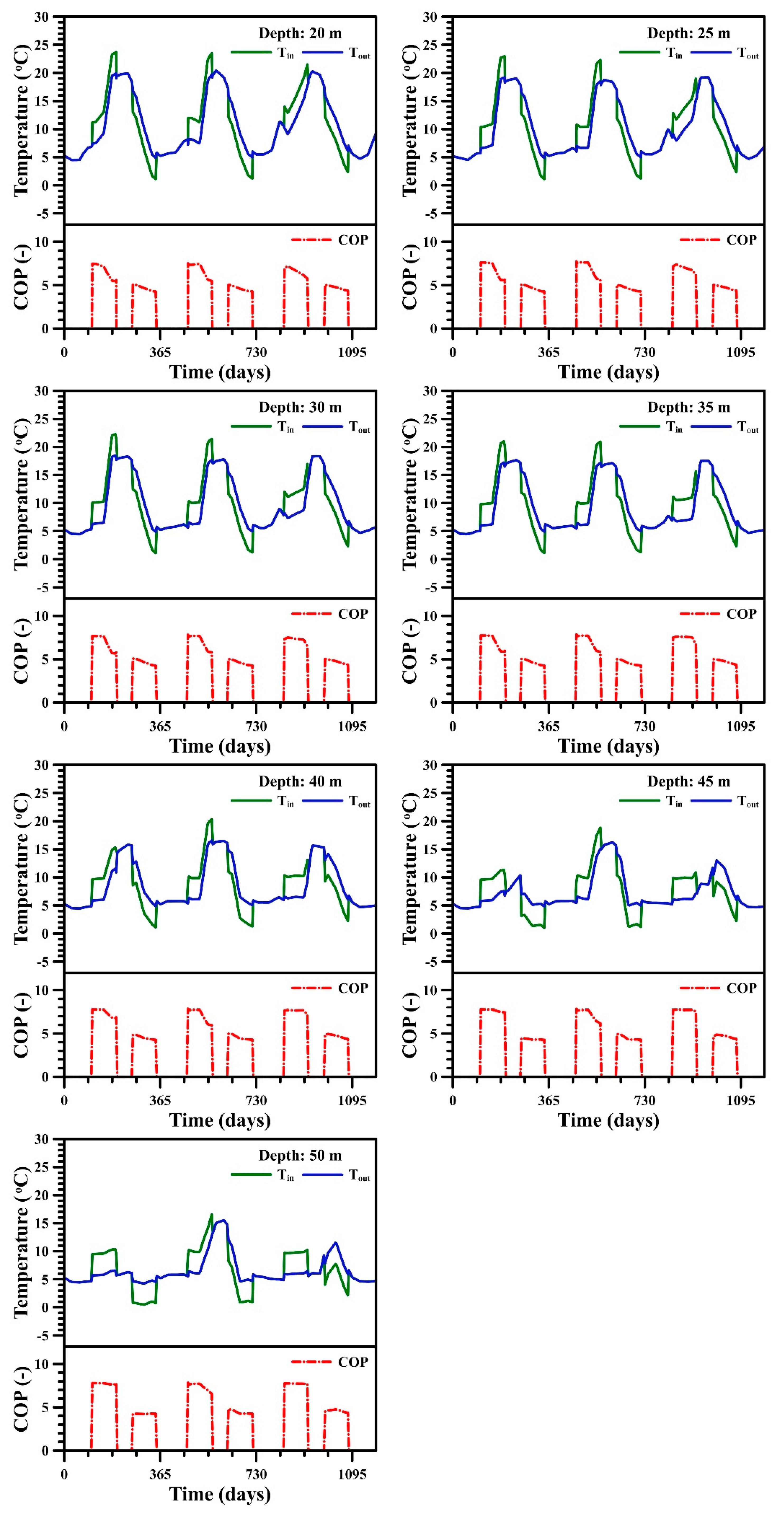
4.2. Installation Depth of Helical Tubes

In the heat pump systems, their performance and efficiency depend mainly on the temperature of the thermal energy source. Lakes have seasonally different temperatures depending on the depths. For the LWHP system, therefore, the installation depth of helical tubes for heat exchange with lake water is likely to be one of the most important considerations in terms of its operational efficiency. To examine the appropriate installation depth, the temperatures of the heat-carrier fluid at the inlet and outlet of the main pipe were calculated with the installation depths from 20 to 50 m (Figure 5 and Figure 6).
For the given installation depths, the mean COP for the total, cooling, and heating operation periods are presented in Table 2. As the bottom of helical tubes was deeper, the system tended to be more efficient for cooling operations, but less efficient for heating operations. Therefore, there must be a trade-off between the installation depths for both of the operation modes. Nevertheless, the cooling COP was more sensitive to the outlet temperature than the heating COP, according to the COP-temperature relation (Figure 4). In addition, the mean water temperatures measured in the lake were 10.53 °C at 20 m deep and 5.39 °C at 50 m deep in summer, respectively, while those were 11.57 °C and 7.68 °C at the same depths in winter. Table 2 shows that increasing the installation depth can improve the efficiency of the cooling operation even more, as well as offsetting some loss in the efficiency of the heating operation. Consequently, the placement of tubes at a depth of 50 m, having the highest total COP value, could be regarded as one of the ways to achieve an efficient operation over the entire period, while the COP calculations were affected by the extrapolation of the given COP curve.
When helical tubes were placed at the shallow depths, the inlet and outlet temperatures changed abruptly with time, regardless of the season (Figure 6). For the installation depth of 20 m, for example, the outlet temperature reached about 20 °C during every summer and dropped up to about 5 °C every winter. As a result, the COP of the system decreased with time during every seasonal operation. If helical tubes were placed deeper, however, the changes in temperatures were mitigated and, thus, it could prevent deterioration of the thermal efficiency with time. These results were strongly related to the monthly variations in the temperature-depth profile in the lake. Because the temperatures of lake water at the shallow depths were highly dependent on the seasonal air temperature variations, an LWHP system installed at such a depth was likely to be faced with unfavorable conditions as each season progressed.

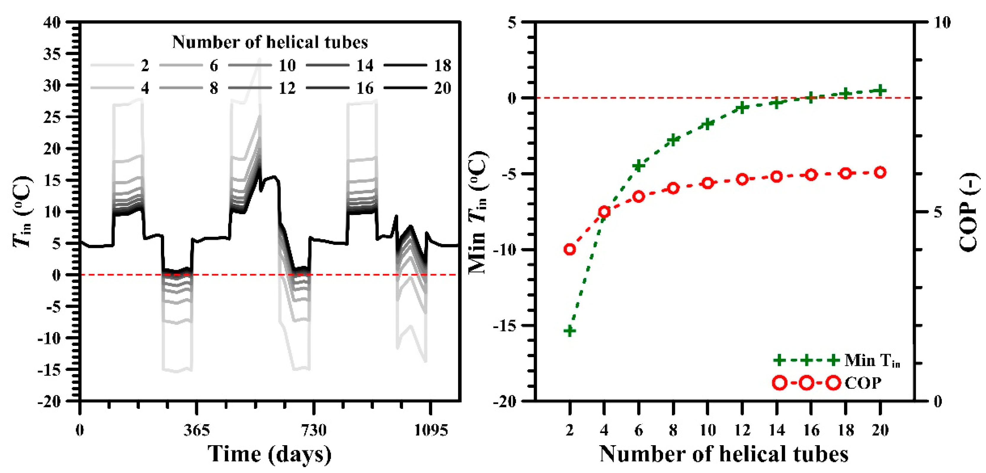
4.3. Number of Helical Tubes

After deciding the installation depth, the performance and efficiency of the LWHP systems with 2 to 20 helical tubes were, respectively, evaluated to determine the number of helical tubes suitable to the given cooling and heating loads. The efficiency of the LWHP system can be improved as more helical tubes are used (Figure 7). If only not enough helical tubes are installed, the heat-carrier fluid in its circulation loop might not exchange its heat with surrounding lake water sufficiently. As a result, the fluid without full recovery of the temperature can flow into the heat pump, and then the resulting inlet temperature for cooling operations would steadily increase or decrease for heating operations. In this thermal feedback process, the resulting changes in the temperature would be enforced and, eventually, the efficiency of the system must be impaired significantly. It implies that a sufficient number of helical tubes are required to be installed to guarantee efficient operation.
The number of helical tubes must be related to installation and operation costs, including tube length and electric energy consumed for heat-carrier fluid circulation, as well as the capacity of heat exchange with the lake water. Obviously, the COP monotonically increased with the number of helical tubes, but its rate decreased gradually. In addition, the inlet temperature in winter should not be lower than the freezing point of the heat-carrier fluid for the stable operation. Figure 7 also shows that more than 16 helical tubes can keep the minimum inlet temperature above 0 °C and can satisfy given thermal loads in this study. From these results, 16 helical tubes could be more appropriate in cost than the base case configuration.

4.4. Flow Rate of the Heat-Carrier Fluid

The sensitivity of the flow rate of the heat-carrier fluid on the operation of the LWHP system in Lake Soyang was investigated by a setting of 75.71–227.1 L/min. In the previous steps, the installation depth and the number of helical tubes were determined using the flow rate of the heat-carrier fluid of 189.3 L/min. Therefore, the inlet temperature with higher than 189.3 L/min of the flow rate can be maintained above 0 °C during the heating operation (Figure 8).
During the operation seasons, the changes in the inlet temperature increased greatly with decreasing flow rate. It was due to the fact that the flow rate determines the temperature difference for given cooling or heating loads. Under the low flow rate conditions, the temperature difference must be increased because of the reduction of volume of the heat-carrier fluid that passes the heat-exchanger of the heat pump per unit time. The heat exchange through the tube wall can be improved as the flow rate increases. Nevertheless, the outlet temperatures computed under the fast flow conditions were higher during cooling operations and lower during heating operations than those of the slow flow conditions because the convective heat transfer of the fluid from the inlet to the outlet along the pipe was improved significantly under the simulation conditions. As a result, the total COP tended to decrease slightly by increasing the flow rate. Due to the combining effects of both processes, the operation with the flow rate of 75.71 L/min seemed to have the highest COP, but the resulting minimum inlet temperature was dropped to −4.6 °C, as shown in Figure 8. Under the installation conditions determined previously, the default flow rate was the operation option that had the highest COP as well as avoiding the freezing of the heat-carrier fluid.

4.5. Properties of Helical Tubes

The sensitivities of three properties of helical tubes, including the inner diameter, the thickness, and the thermal conductivity of tubes, were investigated based on the previously determined conditions. The circulation flow and the resulting heat fluxes of the heat-carrier fluid in tubes depend on the tube diameter and, eventually the resulting cross-sectional area. For a given volumetric flow rate, the flow velocity of the heat-carrier fluid would slow down as the tube diameter increased. As also mentioned in the previous chapter, consequently, increasing the diameter of the tube may lead to improved heat exchange with the lake water. It can also have an influence on the head loss caused by friction in the main pipe and tubes. According to Equations (4) and (5), friction in a pipe increases with decreasing the diameter. Figure 9a depicts a combination of these effects of the tube diameter, which showed a slight difference in the COPs estimated within a given range of the diameter.
The thickness and the thermal conductivity of the helical tube wall are related to the heat transfer of the carrier-fluid in the tube with the lake water, according to Equation (9). Although a thick tube wall might help to enhance the strength of the tube, it could obstruct the heat transfer between the circulation fluid and the lake water. In addition, a tube with a high thermal conductivity of the wall would facilitate heat exchange with the lake water. Consequently, the COP and the minimum inlet temperature increased with decreasing the wall thickness (Figure 9b) and increasing the thermal conductivity of tubes (Figure 9c).

4.6. Flow Velocity in Lake

The flow velocity of lake water must also be one of the considerations for the operation of the LWHP system. As shown in Equations (13) and (14), it is related to external forced convection around tubes and can affect the resulting heat transfer of the heat-carrier fluid. Because of no data measured in Lake Soyang, flow velocity in the lake was assigned to be 0.2 m/s for the simulations to assume a mild current in the lake. However, the Soyanggang dam has controlled the water level and discharge of the reservoir for multi-purposes, including flooding control of the Han River. According to precipitation and the corresponding dam operation, the flow velocity may vary temporally even if it remains constant for most of the year. Figure 10 depicts the performances of the LWHP system computed with the varying flow velocity. The minimum inlet temperature tended to decrease with decreasing the flow velocity of the lake water, but its variation was not significant. Similarly, the COPs seem to be relatively insensitive to the lake flow velocity comparing to the other installation and operation factors discussed above.

5. Discussion and Conclusions

This study revealed the potential of the LWHP system as a viable option to utilize and supply a significant amount of unused geothermal energy stored in the many reservoirs in Korea. For this, based on the temperature-depth data measured in Lake Soyang for 4 years, a series of numerical simulations carried out to demonstrate the applicability of the LWHP system using thermal energy within the water in the lake and to suggest the installation and operation scheme suitable to temperature conditions of the lake. As well, through the sensitivity analysis, the performance of the LWHP system was investigated with various installation and operation factors. Results show that for the lake with a mild current, the operation of an LWHP system can be efficient and stable under the conditions that 16 helical tubes are installed at 50 m deep, and the heat-carrier fluid is circulated with the flow rate of 189.3 L/min; the inner diameter, the wall thickness, and the thermal conductivity of the tube are 32 mm, 2.9 mm, and 0.4 W/mK, respectively. When the application of an LWHP system is planned at a lake, the main consideration must be the installation depth of tubes for heat exchange with lake water as the performance of the system primarily depends on the temperature of lake water at that depth. Lakes might have different temperature-depth profiles according to weather conditions every year. Before the application of an LWHP system, therefore, it would be necessary to continuously monitor seasonal changes of temperatures with depths in a lake for the stable operation of the system. In this respect, there is no doubt that the long-term temperature measurements in Lake Soyang must be very valuable for examining the applicability of the LWHP system at the lake. In addition, the installation depth of helical tubes was determined by evaluating the total COP averaged over both operating seasons in this study. However, it can be reasonable to adjust the installation depth with the appropriate temperature for the operation purpose of each season, if it is possible technically. The remaining considerations for the application of the LWHP system, including the number of helical tubes, the flow rate of the heat-carrier fluid, and the tube material properties, could be determined by evaluating site-specific conditions such as cooling and heating requirements, costs, and operational stability, as well as system efficiency. In this study, it was demonstrated that the non-isothermal pipe flow modeling, without considering flow and thermal processes in the lake, was practical enough to design and evaluate the installation and operation of the LWHP system at the lake. This approach is acceptable only if the corresponding operation would cause no serious changes in temperature, chemistry, and ecology in a lake. However, dynamic hydrological and thermal processes occurring in a lake according to the operation of the system should be assessed more rigorously if there are large-scale cooling and heating loads or strict regulations on the temperature disturbance of lake water.

Author Contributions

Conceptualization, Y.L.; formal analysis, D.K.P., and Y.L.; investigation, D.K.P. and Y.L.; methodology, Y.L.; writing—original draft preparation, D.K.P.; writing—review and editing, Y.L. All authors have read and agreed to the published version of the manuscript.

Funding

This research was supported by the Basic Research Project (20-3411) of the Korea Institute of Geoscience and Mineral Resources (KIGAM) funded by the Ministry of Science, ICT, and Future Planning of Korea.

Acknowledgments

This research was supported by the Basic Research Project (20-3411) of the Korea Institute of Geoscience and Mineral Resources (KIGAM) funded by the Ministry of Science, ICT, and Future Planning of Korea. We thank J.M. Choi for advising us on the intricacies of the heat pump system performance. This article greatly benefited from constructive criticism made by Energies journal reviewers.

Conflicts of Interest

The authors declare no conflict of interest. The funders had no role in the design of the study; in the collection, analyses, or interpretation of data; in the writing of the manuscript, or in the decision to publish the results.

References

  1. Ma, W.; Kim, M.K.; Hao, J. Numerical simulation modeling of a GSHP and WSHP system for an office building in the Hot Summer and Cold Winter Region of China: A Case Study in Suzhou. Sustainablity 2019, 11, 3282. [Google Scholar] [CrossRef] [Green Version]
  2. Spitler, J.D.; Mitchell, M.S. Surface water heat pump systems. In Advances in Ground-Source Heat Pump Systems; Rees, S.J., Ed.; Woodhead Publishing: Cambridge, UK, 2016; pp. 225–246. ISBN 9780081003220. [Google Scholar]
  3. Morton, A.C. Assessing the Performance of a Reservoir-Based Water Source Heat Pump. Master’s Thesis, Universtiy of Strathclyde Engineering, Glasgow, UK, 8 September 2013. [Google Scholar]
  4. Self, S.J.; Reddy, B.V.; Rosen, M.A. Geothermal heat pump systems: Status review and comparison with other heating options. Appl. Energy 2013, 101, 341–348. [Google Scholar] [CrossRef]
  5. Banks, D. An Introduction to Thermogeology: Ground Source Heating and Cooling; Wiley-Blackwell: Oxford, UK, 2012; ISBN 9781118447512. [Google Scholar]
  6. Gaudard, A.; Wüest, A.; Schmid, M. Using lakes and rivers for extraction and disposal of heat: Estimate of regional potentials. Renew. Energy 2019, 134, 330–342. [Google Scholar] [CrossRef]
  7. Yu, Y.; Olson, G. Ground Source Heat Pump Systems. In Handbook of Energy Systems in Green Buildings; Springe: Berlin/Heidelberg, Germany, 2018; pp. 393–472. ISBN 9783662491201. [Google Scholar]
  8. Mitchell, M.S.; Hansen, G.M.; Spitler, J.D. Experimental development of natural convection heat transfer correlations for spiral-helical surface water heat exchangers (1385-RP). Sci. Technol. Built Environ. 2018, 24, 714–725. [Google Scholar] [CrossRef]
  9. Zheng, W.; Zhang, H.; You, S.; Ye, T. The Thermal Characteristics of a Helical Coil Heat Exchanger for Seawater-source Heat Pump in Cold Winter. Procedia Eng. 2016, 146, 549–558. [Google Scholar] [CrossRef] [Green Version]
  10. Zhou, C.; Ni, L.; Yao, Y. Heat transfer analysis of multi-row helically coiled tube heat exchangers for surface water-source heat pump. Energy 2018, 163, 1032–1049. [Google Scholar] [CrossRef]
  11. Zhou, C.; Ni, L.; Ke, Y.; Yao, Y. Experimental study on the thermal performance of multi-row helically coiled tube heat exchanger for surface water-source heat pump. Appl. Therm. Eng. 2019, 149, 1274–1286. [Google Scholar] [CrossRef]
  12. Zhou, C.; Ni, L.; Lin, Z.; Yao, Y. Investigation on heat transfer and pressure drop characteristics of multi-row helically coiled tube heat exchanger for surface water-source heat pump. Int. J. Therm. Sci. 2019, 145. [Google Scholar] [CrossRef]
  13. Chiasson, A.D.; Spitler, J.D.; Rees, S.J.; Smith, M.D. Model for simulating the performance of a shallow pond as a supplemental heat rejecter with closed-loop ground-source heat pump systems. ASHRAE Trans. 2000, 106, 107–121. [Google Scholar]
  14. Büyükalaca, O.; Ekinci, F.; Yılmaz, T. Experimental investigation of Seyhan River and dam lake as heat source–sink for a heat pump. Energy 2003, 28, 157–169. [Google Scholar] [CrossRef]
  15. Schibuola, L.; Scarpa, M. Experimental analysis of the performances of a surface water source heat pump. Energy Build. 2016, 113, 182–188. [Google Scholar] [CrossRef]
  16. Zheng, W.; Ye, T.; You, S.; Zhang, H.; Zheng, X. Experimental Investigation of the Heat Transfer Characteristics of a Helical Coil Heat Exchanger for a Seawater-Source Heat Pump. J. Energy Eng. 2016, 142, 04015013. [Google Scholar] [CrossRef]
  17. Zheng, W.; Zhang, H.; You, S.; Ye, T. Numerical and experimental investigation of a helical coil heat exchanger for seawater-source heat pump in cold region. Int. J. Heat Mass Transf. 2016, 96, 1–10. [Google Scholar] [CrossRef]
  18. Kuyuk, A.; Ghoreishi-Madiseh, S.; Sasmito, A.; Hassani, F. Designing a Large-Scale Lake Cooling System for an Ultra-Deep Mine: A Canadian Case Study. Energies 2019, 12, 811. [Google Scholar] [CrossRef] [Green Version]
  19. Fernández-Seara, J.; Piñeiro-Pontevedra, C.; Dopazo, J.A. On the performance of a vertical helical coil heat exchanger. Numerical model and experimental validation. Appl. Therm. Eng. 2014, 62, 680–689. [Google Scholar] [CrossRef]
  20. Wu, Z.; You, S.; Zhang, H.; Fan, M.; Zheng, W.; Wang, Y.; Zhang, Y. Mathematical Modeling and Performance Analysis of Seawater Heat Exchanger in Closed-Loop Seawater-Source Heat Pump System. J. Energy Eng. 2019, 145, 04019012. [Google Scholar] [CrossRef]
  21. Chen, X.; Zhang, G. Study on the application of closed-loop lake water heat pump systems for lakefront buildings in south China climates. J. Renew. Sustain. Energy 2014, 6, 033125. [Google Scholar] [CrossRef]
  22. MOTIE The 3rd Energy Master Plan (in Korean); Ministry of Trade, Industry and Energy (MOTIE): Sejong-si, Korea, 2019.
  23. KNREC. New & Renewable Energy Statistics 2018, 2019 ed.; Korea New & Renewable Energy Center (KNREC): Ulsan-si, Korea, 2019. (In Korean) [Google Scholar]
  24. K-water. Water for the Future; K-water: Daejeon-si, Korea, 2019. (In Korean) [Google Scholar]
  25. Chen, X.; Zhang, G.; Peng, J.; Lin, X.; Liu, T. The performance of an open-loop lake water heat pump system in south China. Appl. Therm. Eng. 2006, 26, 2255–2261. [Google Scholar] [CrossRef]
  26. Ramamoorthy, M.; Jin, H.; Chiasson, A.D.; Spitler, J.D. Optimal Sizing of Hybrid Ground-Source Heat Pump Systems That Use a Cooling Pond as a Supplemental Heat Rejecter—A system Simulation Approach. ASHRAE Trans. 2001, 107, 26–38. [Google Scholar]
  27. ME. A Study on the Improvement of Lake Environement Survey: Final Report; Ministry of Environment (ME): Sejong-si, Korea, 2013. (In Korean) [Google Scholar]
  28. Lee, H.; Han, H. Analysis of Lake Water Temperature and Seasonal Stratification in the Han River System from Time-Series of Landsat Images. Korean J. Remote Sens. 2005, 21, 253–271. (In Korean) [Google Scholar]
  29. Churchill, S.W. Friction-factor equation spans all fluid-flow regimes. Chem. Eng. 1977, 84, 91–92. [Google Scholar]
  30. Gnielinski, V. New Equations for Heat and Mass Transfer in Turbulent Pipe and Channel Flow. Int. Chem. Eng. 1976, 16, 359–368. [Google Scholar]
  31. Churchill, S.W.; Bernstein, M. A Correlating Equation for Forced Convection From Gases and Liquids to a Circular Cylinder in Crossflow. J. Heat Transf. 1977, 99, 300–306. [Google Scholar] [CrossRef]
Figure 1. The Lake Soyang and the temperature measurement point.
Energies 13 00762 g001
Figure 2. Temperature profile measured in Lake Soyang for 4 years (2001–2004). It was reproduced from Lee and Han [28].
Energies 13 00762 g002
Figure 3. The geometry of the lake water heat pump (LWHP) system in this study.
Energies 13 00762 g003
Figure 4. The relation between the coefficients of performance (COPs) and the temperatures of the entering fluid for a heat pump in this study, assuming the entering air temperature to 29.4 °C db/21.7 °C wb for cooling and to 15.6 °C for heating. The equations were derived by a curve fitting method for the cooling and heating COP data, and the dashed line is a result of extrapolation for the cooling COP.
Energies 13 00762 g004
Figure 5. Temperature distributions of the cooling (top: 150 days) and heating (bottom: 300 days) operations of the LWHP system simulated for the installation depth of 50 m. The color scale bar represents temperature in degrees Celsius.
Energies 13 00762 g005
Figure 6. The predicted inlet (Tin) and outlet temperatures (Tout) of the heat-carrier fluid with respect to installation depths.
Energies 13 00762 g006
Figure 7. The changes in inlet temperature (Tin) (left) and the minimum Tin and total COP (right) with respect to the number of helical tubes.
Energies 13 00762 g007
Figure 8. The minimum inlet temperature (Tin) and the total COP with respect to the flow rate of the heat-carrier fluid.
Energies 13 00762 g008
Figure 9. The minimum inlet temperatures (Min Tin) and the total COPs with respect to the properties of helical tubes: (a) Inner diameter, (b) wall thickness, and (c) thermal conductivity of wall.
Energies 13 00762 g009
Figure 10. The minimum inlet temperatures and the total COPs with respect to the flow velocity of the lake water.
Energies 13 00762 g010
Table 1. Summary of the installation and operation parameters in this study.
ParametersRange of ValueCorresponding Chapter
Installation depth (m)20, 25, 30, 35, 40, 45, 50 *4.2
Number of helical tubes2, 4, 6, 8, 10, 12, 14, 16 *, 18, 204.3
Flow rate of heat-carrier fluid (L/min)75.71, 113.6, 151.4, 189.3 *, 227.14.4
Inner diameter of tube (mm)25, 32 *, 404.5
Tube wall thickness (mm)2.9 *, 4.0, 7.04.5
Thermal conductivity of tube wall (W/mK)0.2, 0.4 *, 0.64.5
Lake water velocity (m/s)0.01, 0.02, 0.1, 0.2 *, 0.34.6
* The parameter values with the highest COP.
Table 2. The COPs estimated for the installation depths.
Installation Depth (m)
20253035404550
Cooling COP6.696.947.097.217.397.547.63
Heating COP4.674.674.674.664.594.504.42
Total COP5.685.815.895.946.06.036.04

