Abstract
Borehole breakouts appear in drilling and production operations when rock subjected to in situ stress experiences shear failure. However, if a borehole breakout occurs, the boundary of the borehole is no longer circular and the stress distribution around it is different. So, the interpretation of the hydraulic fracturing test results based on the Kirsch solution may not be valid. Therefore, it is important to investigate the factors that may affect the correct interpretation of the breakdown pressure in a hydraulic fracturing test for a borehole that had breakouts. In this paper, two steps are taken to implement this investigation. First, sets of finite element modeling provide sets of data on borehole breakout measures. Second, for a given measure of borehole breakouts, according to the linear relation between the mud pressure and the stress on the borehole wall, the breakdown pressure considering the borehole breakouts is acquired by applying different mud pressure in the model. Results show the difference between the breakdown pressure of a circular borehole and that of borehole that had breakouts could be as large as 82% in some situations.
1. Introduction
The in situ stress is of fundamental importance in petroleum engineering and geology, and it’s desirable to determine the stress field from borehole data [1,2]. The stress inside a solid cannot be measured directly, so the in situ stress has to be determined by indirect methods. The Kirsch equation is the first solution in elastic theory for the stresses in an infinite plate containing a circular hole. So far, the vertical stress is estimated by the overburden pressure, and the minimum horizontal principal stress is determined by hydraulic fracturing, but the maximum horizontal principal stress is the most difficult component of stress tensor to accurately estimate. Conventionally, the maximum horizontal stress is estimated by the minimum horizontal principal stress and breakdown pressure based on Kirsch equation [3,4,5,6,7], so the accuracy of breakdown pressure is a key point to determine the maximum horizontal stress. However, because Kirsch solution is based on a circular borehole, if a borehole breakout occurs, the boundary of the borehole is no longer circular and the stress distribution around it is different froma circular borehole. Therefore, the interpretation of the hydraulic fracturing results based on the breakdown pressure derived from the Kirsch equation may not be valid, which leads to imprecision for determination of the maximum horizontal stress. Therefore, the investigation on how borehole breakouts influence the breakdown pressure in a hydraulic fracturing test is important for determining the maximum horizontal stress, and the influence of borehole breakouts on breakdown pressure is studied in this paper.
Borehole breakouts represent the rock failure that occurs around the borehole when the induced stresses exceed the rock strength. Borehole breakouts were observed in a gold mine as early as fifty years ago [8], and then were reported in oil wells [9]. Later on, Carr pointed out that borehole breakout direction was consistent with the direction of the minimum in situ horizontal principal stress [10], which is verified by Bell and Gough [11] and Zoback et al. [12]. Laboratory experiments supported the phenomenon that the borehole breakouts are aligned with the direction of the minimum in situ horizontal principal stress [13,14,15].
Numerous attempts have been made to explain the mechanism that brings about the phenomenon of borehole breakouts. By incorporating Mohr-Coulomb criterion to the Kirsch equation, the initial breakout zone can be defined analytically [12]. However, once the initial zone of rock on the borehole wall is broken, the stress condition will change, and the newly exposed rock will be subjected to new stress conditions and a new breakout zone will emerge. There is no analytical solution to describe the new breakout zone. Later on, a numerical model was used to analyze the borehole breakout growth, and it was found that the borehole cross section extends in the direction of the minimum principal stress according to the redistribution of the stresses around the borehole, resulting in continuously increasing stress concentrations around the borehole [13]. Some factors affecting the initiation, propagation, and stability of borehole breakouts have been studied in linearly elastic, homogeneous, and isotropic materials and it was found that the depth of breakouts increases till a stable state, but the width of breakouts remains unchanged [16]. The micromechanisms about borehole breakouts have also been investigated and it was found that the borehole breakouts occur by a series of successive spalls that result from shear failure subparallel to the direction of the local minimum principal stress [14,15,17,18,19]. Some other numerical methods, such as discrete element and finite element methods, were also used to analyze the breakout geometries mechanisms recently [20,21,22,23,24].
Nowadays, as the drilling depth increases, stresses close to the borehole wall become more complex, and more and more borehole breakouts occur in the deep drilling. An appropriate breakout does not cause an unbearable wellbore collapse in the drilling practices [12,25,26,27,28,29,30,31,32,33]. Usually, althoughthe borehole breakout exists, it is minor and cannot cause collapse accidents. This phenomenon has been verified by a large amount of imaging logging. Zoback et al. proposed the wellbore stability model, called the breakout width model, on the basis of the permissible breakout width [12]. Then, for a breakout borehole, conventional methods based on a circular borehole to determine the maximum horizontal earth stress from breakdown pressure and the minimum in situ stress are improper. The influence of a borehole breakout on breakdown pressure isconsidered in thisstudy.
Recently, some researchers studied the influence of noncircular wellbore. Exadaktylos et al. presented a semianalytical solution of notched hole and thought that the geometry of notched configurations can greatly influence the load-bearing capacity of the rock structure and consequently its stability [34]. Zhang et al. studied the initiation and growth of a hydraulic fracture from a circular and a non-circular wellbore, and it was found that hydraulic fracture initiation and growth from a non-circular wellbore is different from initiation from a circular wellbore owing to the change in stress near the well [35,36]. By analyzing wellbore stability and well path optimization based on the breakout width, Ma et al. found that the safe mud weight and the most stable path are different from the traditional method when breakout width is considered [37]. Krzysztof considered the influence of additional dynamic loads from rock mass tremors in underground ore mining [38]. Based on the displacement discontinuity method and the fictitious stress method, Varahanaresh developed a hydraulic fracture propagation model to study the effect of rock anisotropy on fracture propagation near and away from the wellbore, and results indicate that fracture apertures near the wellbore are significantly affected by rock anisotropy [39]. In addition, Al-Ajmi and Zimmerman [40], Chen et al. [41], and Qi et al. [42] researched the optimization method of well path based on the in situ stress, but the optimized well path may be contrary to conventional knowledge. Once the influence of the permissible breakout width is considered, the optimized well path may be more consistent with the actual situation. Thus, the optimization method of well path must be improved to match the drilling practices. All of these studies show that there is an influence on the stress near the borehole wall from a borehole breakout, which means the determination of the maximum earth stress based on Kirsch solution and breakdown pressure is improper. Thus, how the borehole breakout impacts breakdown pressure becomes more important for in situ stress determination in deep drilling.
In this paper, the influence of borehole breakouts on breakdown pressure is studied, and the investigation of breakdown pressure of a borehole that had breakouts is performed in two steps. First, sets of finite element modeling provide sets of data on borehole breakout measures according to different in situ stresses. Second, for a given measure of borehole breakouts, according to the linear relation between the mud pressure and the stress on the borehole wall, the breakdown pressure considering the borehole breakouts can be acquired by applying different mud pressure in the model. By analyzing the error of breakdown pressure between circular and breakout borehole in different conditions, the applicability of Kirsch solution to determine the maximum horizontal principal stress is obtained in this study, which increases the accuracy of estimation of the maximum horizontal principal stress.
2. Model Structure and Methodology
2.1. Rock Failure Criterion
2.1.1. Rock Compression Failure Criterion
The Mohr–Coulomb failure criterion is chosen to be applied in this paper to predict the borehole breakout, which is given by:
in which
where is cohesive strength, is internal friction angle, is the normal stress on the failure plane, is the shear stress on the failure plane, and are the maximum and minimum principal stresses, respectively.
Based on Mohr–Coulomb failure criterion, if , no failure happened for the rock; if , rock failures [43]. So, Equation (1) can be shortened as:
where, .
2.1.2. Rock Tension Failure Criterion
The tensile strength failure criterion is used in this paper to predict the borehole breakdown pressure [43].
where, is tensile strength of rock.
2.2. Analytical Solution for the Width of Breakouts
Because the initial breakout zones extend in the direction of the minimum principal stress, and the width of breakouts remains stable [16], the initial breakout width can be considered as the final breakout width, which is the analytical solution for the width of breakouts. The breakout width can be obtained by incorporating the Kirsch equation into the failure criterion.
The Kirsch equation can be written as follows [3].
where is the radial stress, is the circumferential stress, is the vertical stress, is the tangential shear stress, is horizontal maximum in situ stress, is horizontal minimum in situ stress, is vertical in situ stress, is Poisson’s ratio, is the radius of a borehole, is distance from the center of the borehole, is the angle from the maximum principal stress, is the fluid pressure in the borehole.
In the condition of and , incorporating Equations (4a)–(4d) into Equation (1), Equation (5) can be obtained for the width of borehole breakouts, which is shown in Figure 1. In Figure 1, is breakout depth.
in which
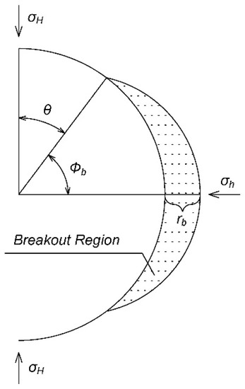
Figure 1.
Schematic of a borehole breakout shape.
Based on the Kirsch equation, the analytical solution of breakdown pressure for the circular borehole can be obtained as follows.
2.3. Simulation of the Borehole Breakouts by the Finite Element Method
Borehole breakouts occur as a series of successive spalls in the direction of the local minimum principal stress that result from shear failure and are sub parallel to the free surface of the borehole wall [16,17,19].
Figure 2 shows the schematic of a typical borehole breakout process, where (1), (2), (n) represent the failure regions of each cyclic process, respectively; 1, 2, n represent the surface of a breakout of each cyclic process, respectively.
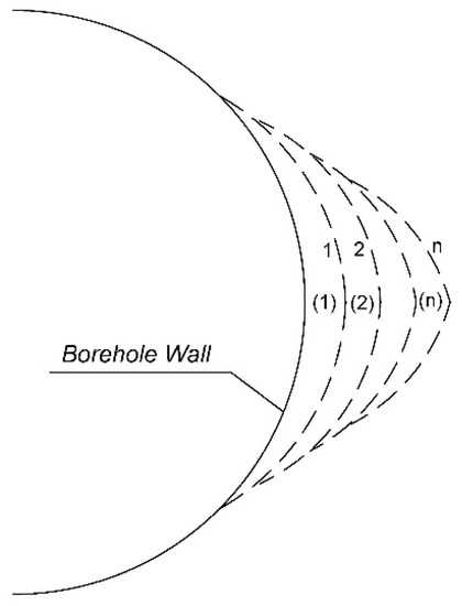
Figure 2.
Schematic of a borehole breakout process.
Numerical simulation of borehole breakouts can be implemented by the following steps:
Step 1: Build a finite element model; apply boundary condition; analyze and determine the stress distribution.
Step 2: Determine the scope of failure (1) by Mohr–Coulomb failure criterion.
Step 3: Take the elements in the failure scope out by changing the position of nodes of borehole wall from circular wall to curve 1, and generate a new noncircular borehole wall along curve 1.
Step 4: Recalculate the stresses distribution based on noncircular borehole wall generated by Step 3 and ascertain the scope of failure (2).
Step 5: Take the elements in the failure scope out by changing the position of nodes of borehole wall from curve 1 to curve 2, and generate a new noncircular borehole wall along curve 2.
Step 6: Rerun Step 4 and Step 5 until no new failure scope occurs, and the stable shape of breakouts is obtained, which is shown as curve n in Figure 2.
Step 7: Write down the shape of borehole breakout, which is shown as curve n in Figure 2, and calculation is finished.
The flow chart is shown in Figure 3.
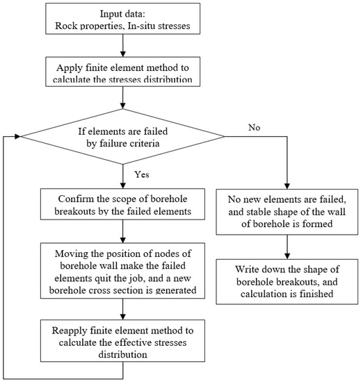
Figure 3.
Flow chart for thefinite element method.
2.4. Finite Element Implementation
Analytical solutions of stress distribution around a borehole can be acquired from theKirsch Equation, which is just for a regular circular borehole. When borehole breakouts occur, there is no analytical solution available to predict its growth. Therefore a numerical model is necessarily introduced.
2.4.1. Constitutive Model
A linear elastic model is chosen to be applied in this paper to predict a borehole breakout, which is given by [43]:
in which is stress vector, is strain vector, is the elastic stiffness matrix.
where is Young’s modulus, is Poisson’s ratio.
2.4.2. Elements Choosing
Because a borehole breakout is a complex process, and vertical stress close to the borehole wall is changing in the process of breakout, space elements is easier than plane strain elements. Because a linear elastic model is adopted in this paper, the computation is not much, so 8-node space isoparametric elements are used in this paper.
2.4.3. Governing Equations
The governing equations of equilibrium for elasticity can be described as:
where is stress vector, is nodal loads vector, and are Lame constants.
The Galerkin finite element method is used herein to approximate above governing equations [44]. The displacement vector at any point within an element can be expressed by displacement at nodes and shape function. The expression for is:
The final form of the finite element equation is as follows:
where is elastic stiffness, is vector for unknown displacement, is the vector for the nodal loads. The explicit expression for is:
where is the strain matrix, is the elastic stiffness matrix.
3. Verification and Numerical Experiments
3.1. Finite Element Model for Borehole Breakouts
For a vertical borehole shown in Figure 4 that is subjected to horizontal in situ stresses and , the shape of breakouts and can be acquired by finite element modeling, where is the depth of breakouts, and is the width of breakouts (Figure 1). A linear elastic model is chosen to be applied to predict a borehole breakout, and 8-node space isoparametric elements are used, and the total number of elements is 450. The finite element mesh of the model is shown in Figure 4.
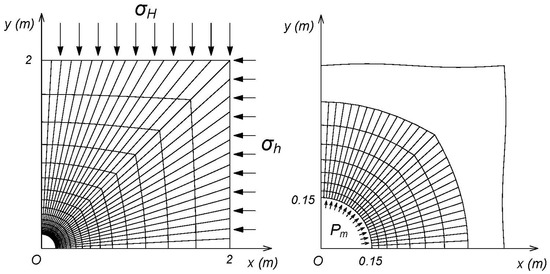
Figure 4.
Mesh of finite element model.

Table 1.
Geometric and mechanical parameters.
Table 2.
Maximum and minimum principal stresses (MPa).
3.2. Verification of the Finite Element Model for Borehole Breakouts
By incorporating Mohr–Coulomb criterion into the Kirsch equation, the initial breakout zone can be defined analytically [12]. Because the initial breakout zones extend in the direction of the minimum principal stress, and the width of breakouts remains stable [16], the initial breakout width can be considered as the final breakout width, which is theanalytical solution for the width of breakouts. The breakout width can be obtained by incorporating theKirsch equation into failure criterion. The breakout width for analytical and numerical solution is compared to verify the accuracy of finite element mode in this section.
Table 3 shows different breakout depths corresponding to different in situ stresses and Table 4 shows different breakout width corresponding to different in situ stresses for analytical and numerical solution. The comparison between the obtained breakout width by analytical solution and numerical modeling is shown in the Table 4 and Figure 5 in terms of relative error.
Table 3.
Result of the depth of borehole breakouts (mm).
Table 4.
Result of the width of borehole breakouts (°).
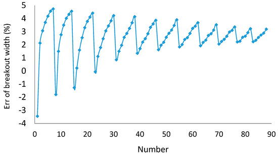
Figure 5.
Error of breakout width between analytical and numerical solutions.
3.3. Relationship between In Situ Stress and a Borehole Breakout
Table 3 and Table 4 show different breakout depthsand widths corresponding to different in situ stresses by finite element modeling.
According to Figure 6, all curves intersect at one point. That is because, based on Equation (5), when = 30°, 98.88 MPa, no matter what value equals to.
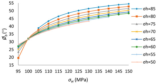
Figure 6.
Breakout width for different in situ stresses (x-coordinate is ).
From Table 3 and Table 4, the relationship between breakout shape and in situ stresses are demonstrated in Figure 6, Figure 7, Figure 8, Figure 9 and Figure 10, from which some conclusions can be made as follows:
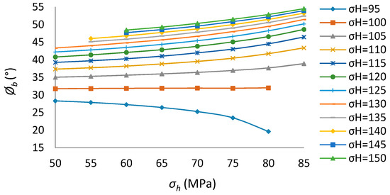
Figure 7.
Breakout width for different in situ stresses (x-coordinate is ).
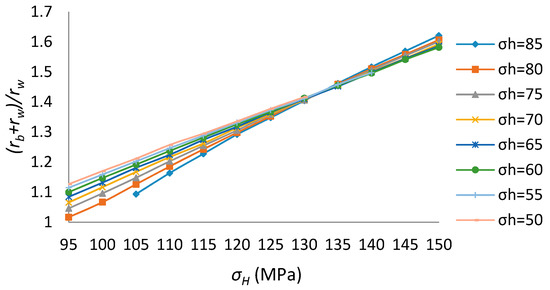
Figure 8.
Breakout depth for different in situ stresses (x-coordinate is ).
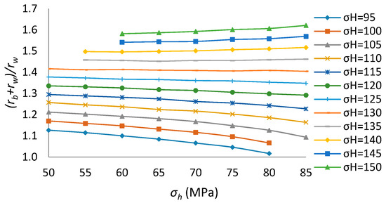
Figure 9.
Breakout depth for different in situ stresses (x-coordinate is σh).
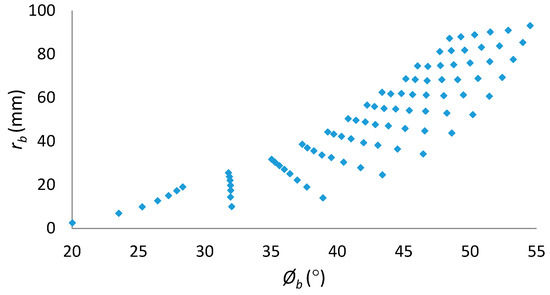
Figure 10.
Relationship between the width and depth of borehole breakout.
1. The relationship between breakout shape and in situ stresses is nonlinear.
2. If the is constant, as increases, the breakout width and depth become greater.
3. In this paper, if 98.88 MPa, the breakout width equals to 30°, no matter what value equals to;if the 98.88 MPa, as increases, the breakout width increases; if the 98.88 MPa, as increases, the breakout width decreases instead.
4. If the difference between and is relatively large, as increases, the breakout depth increases too. However, if the difference between and is relatively small, as increases, the breakout depth decreases instead.
5. Figure 10 shows that one to one correspondence doesnot exist between a breakout width and a breakout depth.
3.4. Analysis of Mesh Dependency (Influence of Finite Element Mesh Size)
Finite element models are built according to different element mesh sizes, and results are shown in Table 5, Table 6, Table 7 and Table 8, in which the total numbers of elements for Size1, Size2, and Size3 are 300, 450, and 600, correspondingly, and the error of breakout depth is relative to breakout depth for Size 3.
Table 5.
Result of borehole breakouts depth (mm) according to different element size.
Table 6.
Difference of borehole breakouts depth (mm) according to different element size.
Table 7.
Result of borehole breakouts width (°) according to different element size.
Table 8.
Error borehole breakouts width (°) according to different element size.
As shown in Table 5, Table 6, Table 7 and Table 8 and Figure 11, Figure 12 and Figure 13, the errors of breakout width and depth for Size1 are significant, which means the size of elements is too large. The errors of breakout width for Size2 and Size3 are less than 5% and the difference of breakout depth between Size2 and Size3 is less than 5%, which means the influence of element size is small when the element number reaches a sufficient level. Thus, in this paper, building thefinite element model by Size2 is satisfactory, where the total number of elements is 450.
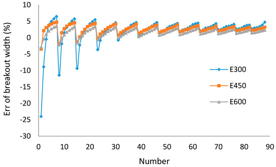
Figure 11.
Error of breakout width between analytical and numerical solutions based on different element size.
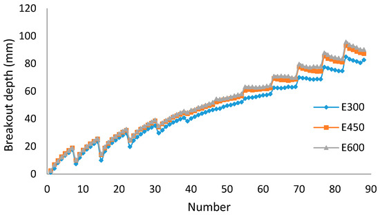
Figure 12.
Breakout depth based on different element size.
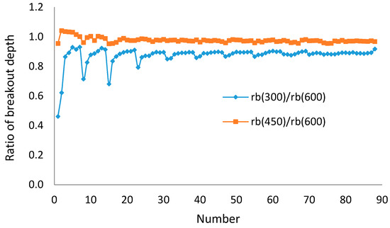
Figure 13.
Ratio of breakout depth based on different element size.
3.5. Verification of the Process of Borehole Breakouts
For a vertical borehole shown in Figure 4 in which horizontal in situ stresses = 100 MPa, = 60 MPa and other values of geometric and mechanical parameters are in Table 1, the process of borehole breakout is shown in Table 9, Table 10, and Figure 14, Figure 15, Figure 16 and Figure 17.
Table 9.
Data of principal stresses (MPa) and breakout region in the process of breakouts.
Table 10.
The breakout shape with number of iterations.
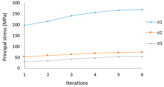
Figure 14.
Variation of principal stresses with number of iterations.
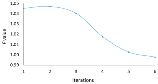
Figure 15.
Variation of F value with number of iterations.
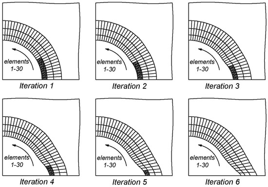
Figure 16.
Process of a borehole breakout with number of iterations.
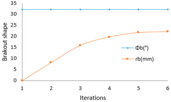
Figure 17.
The breakout shape with number of iterations.
3.6. Numerical Experiments on Breakdown Pressure of the Borehole That Had Breakouts
In this section, a numerical experiment is conducted to investigate the breakdown pressure of the borehole that had breakouts under different in situ stresses. The experiment is for a vertical borehole as shown in Figure 4 in which the values of geometric and mechanical parameters are in Table 11.
Table 11.
Geometric and mechanical parameters.
The investigation is implemented in two steps. First, sets of finite element modeling provide sets of data on borehole breakout measures. Second, for a given measure of borehole breakouts, the breakdown pressure considering the borehole breakouts is acquired by applying different mud pressure in the model, and results are shown in Table 12 and Table 13.
Table 12.
Results of the shape of borehole breakouts.
Table 13.
Results of breakdown pressure (MPa) for circular and breakout boreholes.
Results of the investigation in Table 13 indicate the difference between the breakdown pressure for a circular borehole and the breakdown pressure for a borehole with breakouts. This means that if a breakdown pressure for a borehole with breakouts is interpreted as the analytical breakdown pressure of a circular borehole, there is an error in some situations. It is further found that the breakdown pressure is related to the width or depth of breakouts and the difference betweenbreakdown pressure of circular borehole and mud pressure. The error of breakdown pressure with the circular hole assumption increases with the increase of the breakout’s width or depth and the decrease of the difference betweenbreakdown pressure of circular borehole and mud pressure, which are shown in Table 14, Table 15, and Figure 18, Figure 19 and Figure 20.
Table 14.
Error of breakdown pressure based on (°) and (%).
Table 15.
Error of breakdown pressure based on and (%).
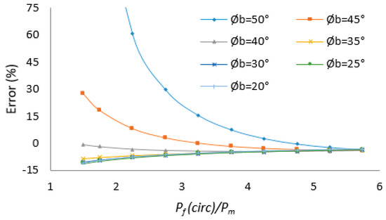
Figure 18.
Error of breakdown pressure based on .
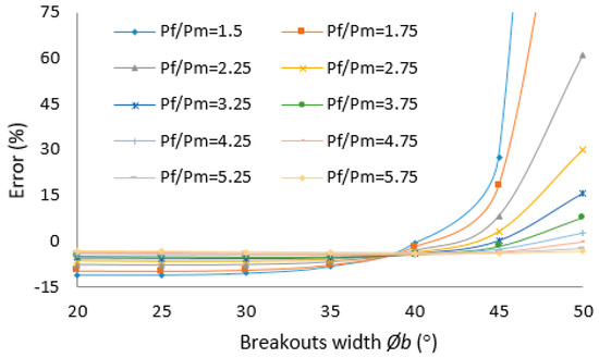
Figure 19.
Error of breakdown pressure based on (°).
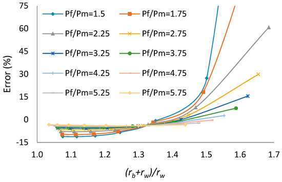
Figure 20.
Error of breakdown pressure based on .
In this paper, based on Table 14, Figure 18, and Figure 19, when , the error of breakdown pressure with circular hole assumption is less than 10%; when and , the error of breakdown pressure with circular hole assumption is less than 10%; when and , the error of breakdown pressure with circular hole assumption is more than 10%; when , the error of breakdown pressure with circular hole assumption is more than 10% most of the time.
In this paper, based on Table 15 and Figure 20, when , the error of breakdown pressure with circular hole assumption is less than 10%; when and , the error of breakdown pressure with circular hole assumption is less than 10%; when and , the error of breakdownpressure with circular hole assumption is more than 10%; when , the error of breakdown pressure with circular hole assumption is more than 10% most of the time.
4. Conclusions
In this paper, the influence of breakouts in a borehole on the breakdown pressure in a hydraulic fracturing test is investigated. The finite element method is employed to simulate the borehole breakouts based on elasticity and Mohr-Coulomb failure criterion, and the obtained breakout measurementsare subsequently conducted to determine breakdown pressures of a borehole under different in situ stresses.
The finite element modeling of borehole breakouts is verified against the analytical solution, with the assumption of successive spalling of thin layers of rock caused by stress redistribution around the borehole and breakouts, which is consistent with previous studies.
From the results of numerical experiments, the influence of borehole breakouts on breakdown pressure is obtained, and the question of when to consider a borehole breakout for determining the maximum horizontal principal stress is resolved.
1. For a breakout borehole, the breakdown pressure is related to breakout width, breakout depth, and initial mud pressure causing a borehole breakout.
2. For a breakout borehole, the closer the breakdown pressure based on the Kirsch solution and initial mud pressure causing the borehole breakout, the greater the error of breakdown pressure based on the Kirsch solution.
3. The larger the borehole breakout, the greater the error of breakdown pressure based onthe Kirsch solution.
4. When a borehole breakout is large or the breakdown pressure based on the Kirsch solution is close to the initial mud pressure causing the borehole breakout, the difference of breakdown pressure between a circular borehole and a breakout borehole is large, and the determination of the maximum horizontal principal stress based on the Kirsch solution is improper, so the influence of borehole breakout should be considered for determining the maximum horizontal principal stress.
5. Modest changes in borehole cross section as a result of breakout do not significantly alter the breakdown pressure from that given by the Kirsch solution for a circular hole subjected to the same in situ stresses, so in this case, the maximum horizontal principal stress can be determined based on the Kirsch solution.
As hydraulic fracturing has been thegold standard in measuring in situ stress in the oil and gas industry, an alert is raised in this paper regardingthe possible consequence of the negligence of the influence of borehole breakout on breakdown pressure interpretation, the most important parameter in hydraulic fracturing tests.
Author Contributions
H.Z. wrote the draft and performed the numerical experiments under the supervision of S.Y. and B.A.
Conflicts of Interest
The authors declare no conflict of interest.
Nomenclature
| Cohesive strength | |
| Internal friction angle | |
| Normal stress on the failure plane | |
| Shear stress on the failure plane | |
| The maximum principal stress | |
| The minimum principal stress | |
| F | Breakout coefficient |
| Tensile strength of rock | |
| Radial stress | |
| Circumferential stress | |
| Vertical stress | |
| Tangential shear stress | |
| The maximum horizontal in situ stress | |
| The minimum horizontal in situ stress | |
| Vertical in situ stress | |
| Radius of a borehole | |
| Distance from the center of the borehole | |
| Angle from the maximum principal stress | |
| Fluid pressure in the borehole | |
| Breakout width | |
| Breakout depth | |
| Breakdown pressure of borehole | |
| Stress vector | |
| Strain vector | |
| Elastic stiffness matrix | |
| Young’s modulus | |
| Poisson’s ratio | |
| Lamé constants | |
| Vector for the nodal loads | |
| Vector for unknown displacement | |
| Node displacement | |
| Shape function | |
| Elastic stiffness | |
| Matrix relating strain and displacement |
References
- Han, H.; Yin, S. Determination of Geomechanical Properties and In-situ Stress from Borehole Deformation. Energies 2018, 11, 131. [Google Scholar] [CrossRef]
- Zhang, H.; Yin, S.; Aadnoy, B. Poroelastic modeling of borehole breakouts for in-situ stress determination by finite element method. J. Pet. Sci. Eng. 2018, 162, 674–684. [Google Scholar] [CrossRef]
- Kirsch, G. Die theorie der elastizitaet und die beduerfnisse der festigkeitslehre. VDI Z. 1898, 29, 797–807. [Google Scholar]
- Schmitt, D.R.; Zoback, M.D. Poroelastic effects in the determination of maximum horizontal principal stress in hydraulic fracturing tests—A proposed breakdown equation employing a modified effective stress relation for tensile failure. Int. J. Rock Mech. Min. Sci. Geomech. Abstr. 1989, 26, 499–506. [Google Scholar] [CrossRef]
- Bell, J.S. Practical methods for estimating in situ stresses for borehole stability applications in sedimentary basins. J. Pet. Sci. Eng. 2003, 38, 111–119. [Google Scholar] [CrossRef]
- Zoback, M.D.; Barton, C.A.; Brudy, M.; Castillo, D.A.; Finkbeiner, T.; Grollimund, B.R.; Moos, D.B.; Peska, P.; Ward, C.D.; Wiprut, D.J. Determination of stress orientation and magnitude in deep wells. Int. J. Rock Mech. Min. Sci. 2003, 40, 1049–1076. [Google Scholar] [CrossRef]
- Thorsen, K. In situ stress estimation using borehole failures—Even for inclined stress tensor. J. Pet. Sci. Eng. 2011, 79, 86–100. [Google Scholar] [CrossRef]
- Leeman, E.R. The treatment of stress in rock: I. The rock stress measurement: II. Borehole rock stress measuring instrument: III. The results of some rock stress investigations. J. S. Afr. Inst. Min. Metall. 1964, 65, 254–284. [Google Scholar]
- Cox, J.W. The high resolution dip meter reveals dip-related borehole and formation characteristics. In Proceedings of the Trans 11th SPWLA logging Symposium, Los Angeles, CA, USA, 3–6 May 1970; pp. D1–D26. [Google Scholar]
- Carr, W.J. Summary of Tectonic and Structural Evidence for Stress Orientation at the Nevada Test Site; Open File Report; US Geological Survey: Denver, CO, USA, 1974; pp. 74–176.
- Bell, J.S.; Gough, D.I. Northeast-Southwest compressive stress in Alberta: Evidence from oil wells. Earth Planet. Sci. Lett. 1979, 45, 475–482. [Google Scholar] [CrossRef]
- Zoback, M.D.; Moos, D.L.; Mastin, L.; Anderson, R.N. Wellbore breakout and in-situ stress. J. Geophys. Res. 1985, 90, 5523–5538. [Google Scholar] [CrossRef]
- Mastin, L. The Development of Borehole Breakouts in Sandstone. Master’s Thesis, Stanford University, Stanford, CA, USA, 1984. [Google Scholar]
- Haimson, B.C.; Herrick, C.G. In situ stress evaluation from borehole breakouts experimental studies. In Proceedings of the 26th US Rock Mechanics Symposium, Rapid City, SD, USA, 26–28 June 1985; Balkema: Rotterdam, The Netherlands, 1985; pp. 1207–1218. [Google Scholar]
- Haimson, B.C.; Herrick, C.G. Borehole breakouts-a new tool for estimating in situ stress? In Proceedings of the First International Symposium on Rock Stress and Rock Stress Measurement; Centek Publications: Luleå, Sweden, 1986; pp. 271–281. [Google Scholar]
- Zheng, Z.; Kemeny, J.; Cook, N.G.W. Analysis of borehole breakouts. J. Geophys. Res. 1989, 94, 7171–7182. [Google Scholar] [CrossRef]
- Yuan, S.C.; Harrison, J.P. Modeling breakout and near-well fluid flow of a borehole in an anisotropic stress field. In Proceedings of the 41st ARMA, Golden, CO, USA, 17–21 June 2006. [Google Scholar]
- Haimson, B.C. Micromechanisms of borehole instability leading to breakouts in rocks. Int. J. Mech. Min. Sci. 2007, 44, 157–173. [Google Scholar] [CrossRef]
- Papamichos, E. Borehole failure analysis in a sandstone under anisotropic stresses. Int. J. Numer. Anal. Methods Geomech. 2010, 34, 581–603. [Google Scholar] [CrossRef]
- Cook, B.K.; Lee, M.Y.; Di, G.A.A.; Bronowski, D.R.; Perkins, E.D.; Williams, J.R. Discrete element modeling applied to laboratory simulation of near-wellbore mechanics. Int. J. Geomech. 2004, 4, 19–27. [Google Scholar] [CrossRef]
- Fakhimi, A.; Carvalho, F.; Ishida, T.; Labuz, J.F. Simulation of failure around a circular opening in rock. Int. J. Rock Mech. Min. Sci. 2002, 39, 507–515. [Google Scholar] [CrossRef]
- Lee, H.; Moon, T.; Haimson, B.C. Borehole Breakouts Induced in Arkosic Sandstones and a Discrete Element Analysis. Rock Mech. Rock Eng. 2016, 49, 1369–1388. [Google Scholar] [CrossRef]
- Gomar, M.; Goodarznia, I.; Shadizadeh, S.R. Transient thermo-poroelastic finite element analysis of borehole breakouts. Int. J. Rock Mech. Min. Sci. 2014, 71, 418–428. [Google Scholar] [CrossRef]
- Rahmati, H. Micromechanical Study of Borehole Breakout Mechanism. Ph.D. Thesis, University of Alberta, Edmonton, AB, USA, 2013. [Google Scholar]
- Zoback, M.D. Reservoir Geomechanics; Petroleum Industry Press: Beijing, China, 2012. [Google Scholar]
- Guenot, A. Borehole breakouts and stress fields. Int. J. Rock Mech. Min. Sci. Geomech. Abstr. 1989, 26, 185–195. [Google Scholar] [CrossRef]
- Haimson, B.C.; Song, I. Laboratory study of borehole breakouts in Cordova Cream: A case of shear failure mechanism. Int. J. Rock Mech. Min. Sci. Geomech. Abstr. 1993, 30, 1047–1056. [Google Scholar] [CrossRef]
- Wang, J.; Deng, J.; Li, B. Numerical Simulation of Borehole Collapse Procedure and Prediction on Well-hole Enlargement. Petrol. Drill. Tech. 2000, 28, 13–14. [Google Scholar]
- Zhang, G.; Chen, M. Correlation between bore hole surrounding rock damage and drilling fluid density. Oil Drill. Prod. Technol. 2002, 24, 31–51. [Google Scholar]
- Zhang, G.; Chen, M. Three-dimensional finite element model for relationship between wellbore failure and mud density. Petrol. Drill. Technol. 2004, 32, 37–38. [Google Scholar]
- Moos, D.; Wilson, S.; Barton, C.E. Impact of rock properties on the relationship between wellbore breakout width and depth. In Proceedings of the 1stCanada—U.S.Rock Mechanics Symposium, Vancouver, BC, Canada, 27–31 May 2007. [Google Scholar]
- Lee, H.; Chang, C.; Ong, S.H.; Song, I. Effect of anisotropic borehole wall failures when estimating in situ stresses: A case study in the Nankai accretionary wedge. Mar. Pet. Geol. 2013, 48, 411–422. [Google Scholar] [CrossRef]
- Meier, T.; Rybacki, E.; Reinicke, A.; Dresen, G. Influence of borehole diameter on the formation of borehole breakouts in black shale. Int. J. Rock Mech. Min. Sci. 2013, 62, 74–85. [Google Scholar] [CrossRef]
- Exadaktylos, G.E.; Liolios, P.A.; Stavropoulou, M.C. A semi-analytical elastic stress-displacement solution for notched circular openings in rocks. Int. J. Solids Struct. 2003, 40, 1165–1187. [Google Scholar] [CrossRef]
- Zhang, X.; Jeffrey, R.G.; Bunger, A.P.; Thiercelin, M. Initiation and growth of a hydraulic fracture from a circular wellbore. Int. J. Rock Mech. Min. Sci. 2011, 48, 984–995. [Google Scholar] [CrossRef]
- Zhang, X.; Jeffrey, R.G.; Bunger, A.P. Hydraulic fracturing growth from a non-circular wellbore. In Proceedings of the 45th US Rock Mechanics/Geomechanics Symposium, San Francisco, CA, USA, 26–29 June 2011. [Google Scholar]
- Ma, T.; Chen, P.; Yang, C.; Zhao, J. Wellbore stability analysis and well path optimization based on the breakout width model and Mogi-Coulomb criterion. J. Pet. Sci. Eng. 2015, 135, 678–701. [Google Scholar] [CrossRef]
- Krzysztof, S. A new design of support for burst-prone rock mass in underground ore mining. In Proceedings of the E3S Web of Conferences 71, 00006, 2018; XVIII Conference of PhD Students and Young Scientists, Szklarska Poreba, Poland, 22–25 May 2018. [Google Scholar]
- Varahanaresh, S.; Ahmad, G. Effect of rock anisotropy on wellbore stresses and hydraulic fracture propagation. Int. J. Rock Mech. Min. Sci. 2018, 112, 369–384. [Google Scholar]
- Al-Ajmi, A.M.; Zimmerman, R.W. A new well path optimization model for increased mechanical borehole stability. J. Pet. Sci. Eng. 2009, 69, 53–62. [Google Scholar] [CrossRef]
- Chen, Z.; Zhang, H.; Shen, B.; Yin, G.; Wang, X. A study on safe and dangerous drilling azimuths of horizontal well. Acta Pet. Sin. 2013, 34, 164–168. [Google Scholar]
- Qi, B.; Chen, P.; Xia, H.; Wei, C. Optimizing the Method Used to Design the Trajectory of a Horizontal Well. Chem. Technol. Fuels Oil. 2014, 50, 337–343. [Google Scholar]
- Aadnoy, B.S.; Looyeh, R. Petroleum Rock Mechanics: Drilling Operations and Well Design, 1st ed.; Gulf Professional Publishing: Oxford, UK, 2011. [Google Scholar]
- Yin, S. Geomechanics—Reservoir Modeling by Displacement Discontinuity—Finite Element Method; University of Waterloo: Waterloo, ON, Canada, 2008. [Google Scholar]
© 2019 by the authors. Licensee MDPI, Basel, Switzerland. This article is an open access article distributed under the terms and conditions of the Creative Commons Attribution (CC BY) license (http://creativecommons.org/licenses/by/4.0/).