1. Introduction
Today, current trends in energy supply are unsustainable from environmental, economic, and social points of view, and stricter low-carbon economy policies push this demand further. Therefore, the development of advanced energy technologies is very much needed [
1,
2]. Crucial players to achieve such sustainable development goals are renewable energies, and in this new scenario concentrated solar power (CSP) is one of the most interesting alternatives [
3,
4].
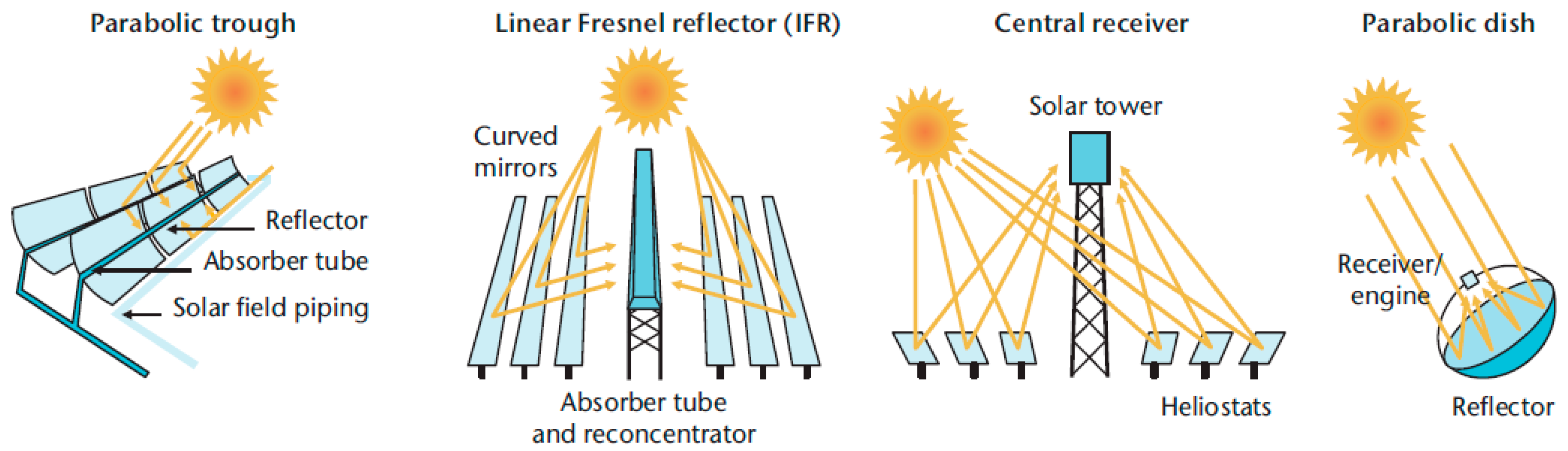
Parabolic trough, linear Fresnel, tower, and parabolic dish are the main different options in CSP technology, depending on how the focus of sunrays and the position of the receiver is implemented (
Figure 1). Line focus systems track the sun with mirrors arranged in one axis (parabolic trough and linear Fresnel systems), while point focus systems use two axes (tower and dish systems). On the other hand, the receiver can be fixed (linear Fresnel and tower systems) or mobile (parabolic trough and dish systems).
Parabolic trough collector (PTC) systems concentrate the sun in a parabolically curved trough-shaped reflector. The receiver is a tube located along the inner side of the collector [
5]. The heat transfer fluid (HTF), usually synthetic oil, is heated by the energy concentrated in the receiver, where it flows through the tube along the trough collector and is then used to generate electricity in a conventional steam turbine generator after a heat transfer exchange with a secondary HTF, water/steam.
The tower technology uses large sun-tracking mirrors, also called heliostats, to focus the sunlight on a receiver that is located at the top of the tower to produce electricity from the sun [
5]. The HTF is usually molten salt or water/steam, and it is heated when it flows through the receiver. Again, it is used in a conventional steam turbine generator to produce electricity, either directly or by using a heat exchanger.
The linear Fresnel technology [
6], on the other hand, uses mirrors mounted on trackers on the ground that are flat or slightly curved. The mirrors reflect sunlight to a receiver tube located above them. Sometimes, a small parabolic mirror is placed on the receiver to increase the focus of the sunlight.
The last technology is parabolic dish systems, in which the concentrator is a dish with a parabolic-shaped focus point, with the receiver located at the focal point [
5]. The sun is tracked with a two-axis structure where the concentrators are mounted. The receiver is usually mounted next to the heat engine that uses the collected heat to produce electricity on site. Here, Stirling and Brayton cycle engines are used.
The HTF, thermal energy storage (TES), and power cycle can be selected from different options in each technology. One of the most important components to achieve high overall performance and efficiency in CSP systems is the HTF [
7]. The main requirements for a proper HTF were summarized by Benoit et al. [
8], based on the review of existing and potential HFTs used in CSP receivers. To increase the efficiency of the cycle, the HTF should be able to work in a wide working temperature range and should present high thermal stability. If this is accomplished, the cost of the solar field, which is the main saving factor in a CSP plant, is reduced. Next, in order to increase the heat transfer between the HTF, the TES material, and the power block driving fluid, and in addition to withstand high pressure and temperature changes, the HTF should have good thermophysical properties. Finally, the HTF should be non-hazardous, have a low corrosive behaviour, and should be cost-effective. More information about different types of HTF suitable for CSP plants and other high temperature applications (such as liquids, supercritical fluids, and gases) is presented in other studies [
7,
9,
10], such information on their cost and thermal and physical properties.
CSP technology with a PTC system is currently the most mature solar technology, leading to the accumulation of relevant operational experience [
11]. The most widely used heat transfer fluid (HTF) in parabolic trough plants is a eutectic mixture of the organic compounds biphenyl oxide and diphenyl oxide [
12,
13,
14]. The operation temperature of the solar thermal power plant is limited to up to 400 °C when using an organic HTF [
14,
15], since when operating above this temperature the HTF degrades [
15].
Significantly higher efficiency of the solar thermal power system can be achieved if a more stable HTF is used, such as binary or ternary mixtures of nitrate salts within the needed operating temperature [
15,
16,
17]. These eutectic mixtures would allow operating temperatures of 500 °C or higher [
10,
16]. The most widely considered candidates are Solar Salt, HiTec
®, and HiTec XL
® [
12,
18]. Solar Salt is a binary salt mixture of 60 wt.% NaNO
3 and 40 wt.% KNO
3. HiTec is a ternary mixture of alkali-nitrates/nitrites, and finally, HiTec XL is a ternary mixture of sodium, potassium, and calcium nitrates. Their melting properties are given in
Table 1.
The biggest drawback of these nitrate salt mixtures is that they freeze inside the tubing in the system, since their melting points vary from 120 °C to 220 °C. Therefore, freeze protection has to be considered in any PTC plant. On the other hand, HiTec XL and HiTec have a lower melting point, therefore the problem of freezing is easier to control. On the other hand, the thermal stability of these mixtures is lower than Solar Salt [
10,
12,
19,
20].
The benefit of using molten salts as heat transfer fluids results from the increase in the allowable maximum operating temperature [
15,
21]. However, molten salts with the desired thermal stability limit have freezing/melting points well above ambient temperature. As such, a freeze protection and recovery system (freeze P/R) is needed for three key functions:
Pre-heat plant for initial salt fill, or pre-heat loops for fill after maintenance.
Prevent freeze events for the duration of the plant life.
Recovery from freeze events for the duration of the plant life.
Preheating of the plant is required to prevent the formation of salt plugs during the initial plant fill and to minimize thermal shock to piping and equipment. Preheating will be needed on a loop level to refill the loop with salt after maintenance has been performed on a loop. Once the plant is filled with salt, the system will then be used to prevent freeze events by maintaining a temperature above the freeze point of the salt, should such situations arise. If a plug or blockage does form anywhere in the plant, the system will apply heat to the affected zone to prevent a larger freezing event and/or melt the frozen zone. The freeze P/R system is not intended to provide heating under normal operation of the plant.
The freeze protection/recovery system proposed in this paper includes two main sections: Heat tracing and impedance heating [
22,
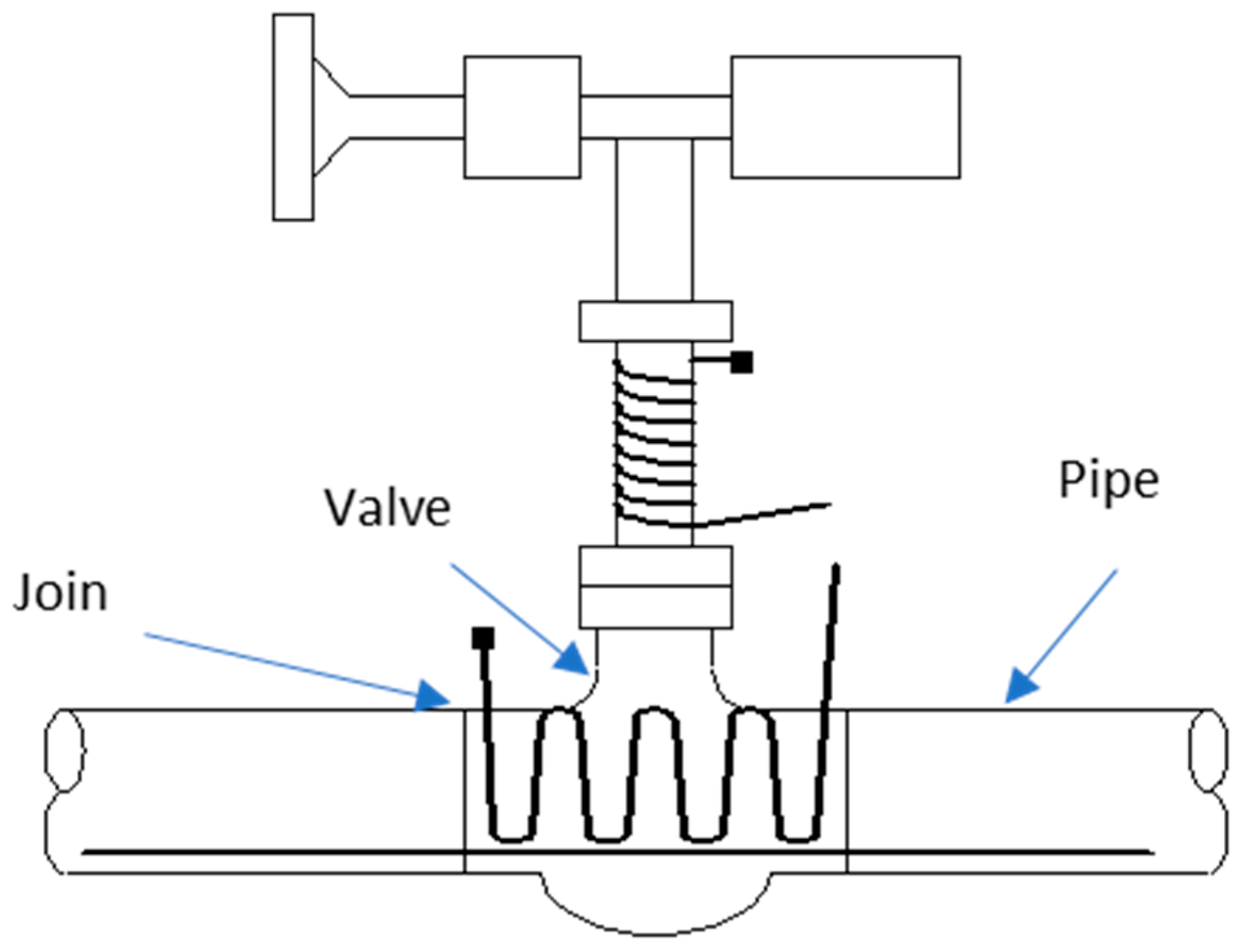
23]. Heat tracing involves the application of heat trace cables to all plant surfaces that might be compromised in a freeze event. This includes all pipes, headers, joints, and valves [
24]. If the plant undergoes a freeze risk, the salt in these areas must be melted. Since no external energy hits these components during normal operation, heat tracing is the only practical option of introducing a heat input.
Impedance melting is accomplished by applying a voltage over a necessary number of absorber tubes in the solar field. This voltage, given a resistivity of the tube, induces a current in the absorber tube that results in a heat generation term.
A good understanding of the working philosophy of freeze protection systems is needed to minimize the parasitic consumption of solar plants, being one of the criteria to select the final HTF in the parabolic trough collector plants. Different modelling studies have been published for state-of-the-art of PTC plants [
11,
25]. However, state-of-the-art PTC plants have never been the subject of a specific feasibility study of heat tracing systems when using high melting point salts as a HTF. The work carried out in this document describes the freeze protection systems used in parabolic trough plants with three mixtures of molten salt, and the modelling for their implementation and optimization in the plant performance model.
4. Results and Discussion
4.1. Results and Discussion for the Heat Tracing System
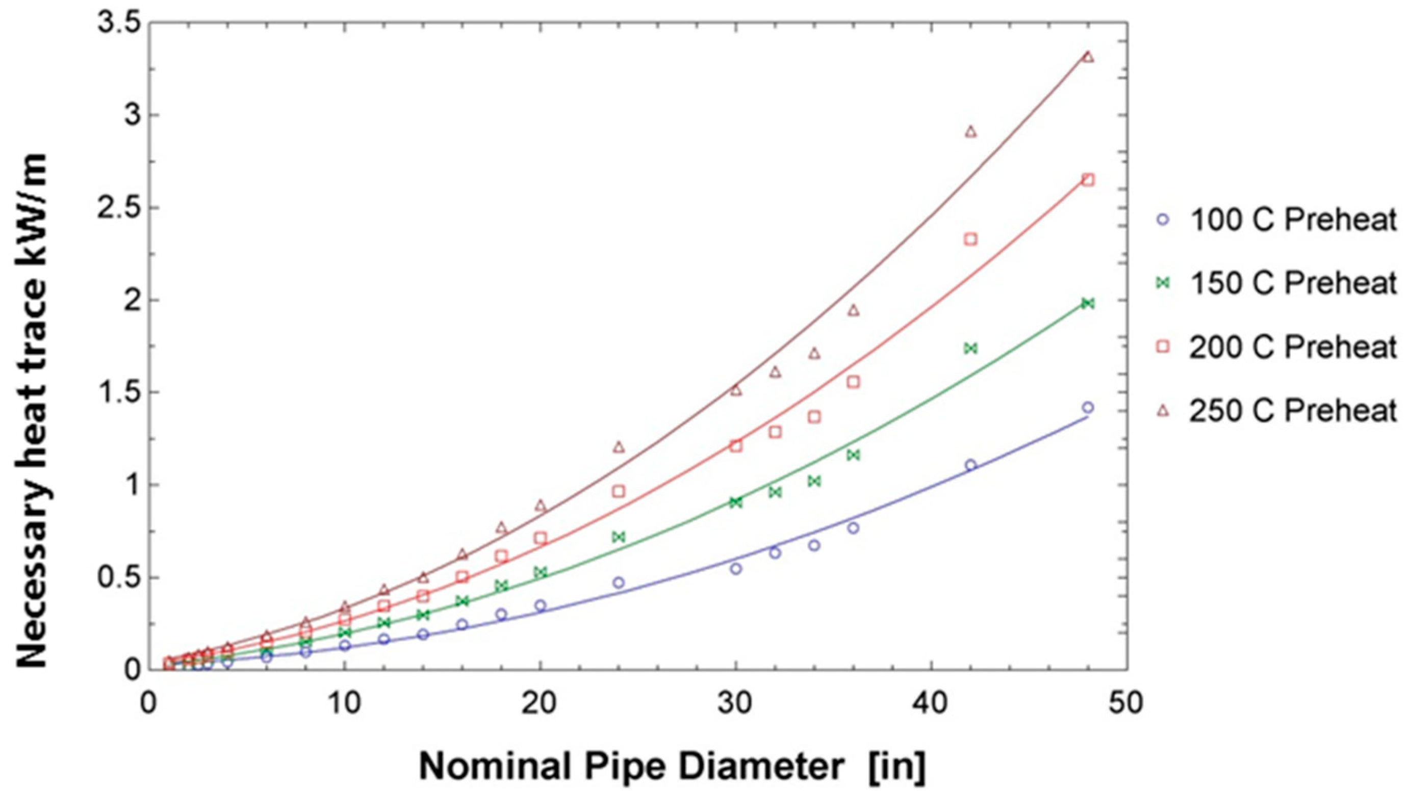
First, results for the pre-heating regime were generated. Based on the pipe diameter and the required pre-heat temperature, the heat trace system can be calculated. The results presented in
Figure 9 show that the heat trace requirements increase with the nominal pipe diameter as expected. Some variation is observed based on the non-linearity of schedule 40 pipe thicknesses.
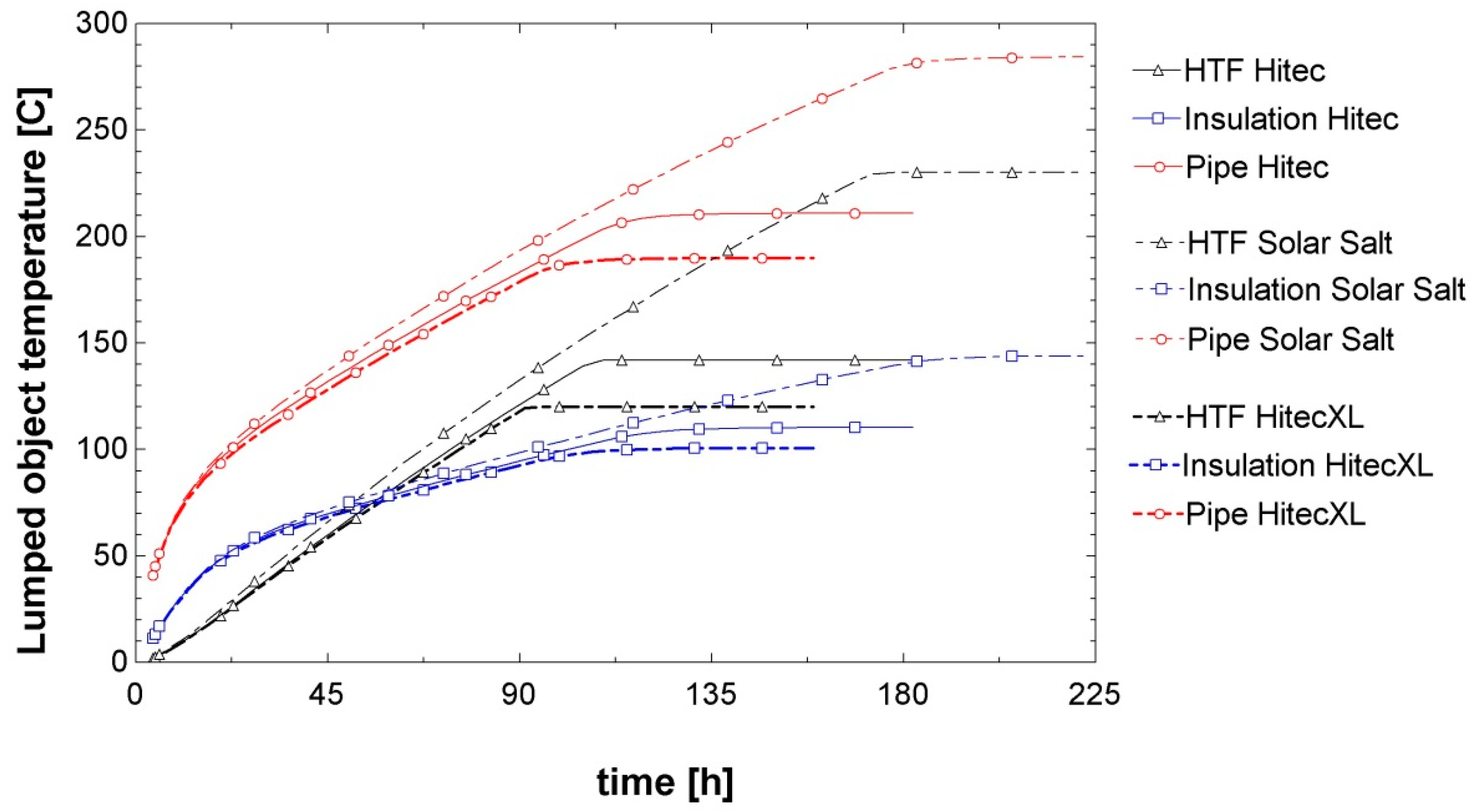
The results in
Figure 10 show the transient behaviour of the system during a freeze recovery. As the salt HTF begins to melt, the temperature value reaches the constant value of the phase change temperature. The figure shows the temperature transients for the pipe, insulation, and internal salt during the freeze recovery process for each candidate salt using a heat trace system. This is designed for an 8 h preheat to 100 °C for a 48” pipe, with a wind speed of 5 m/s and an ambient temperature of 15 °C. The line type denotes the HTF type and the colour/symbol denotes the system component. The melting process is finished when the lines stop.
Further investigation of the melting time was performed.
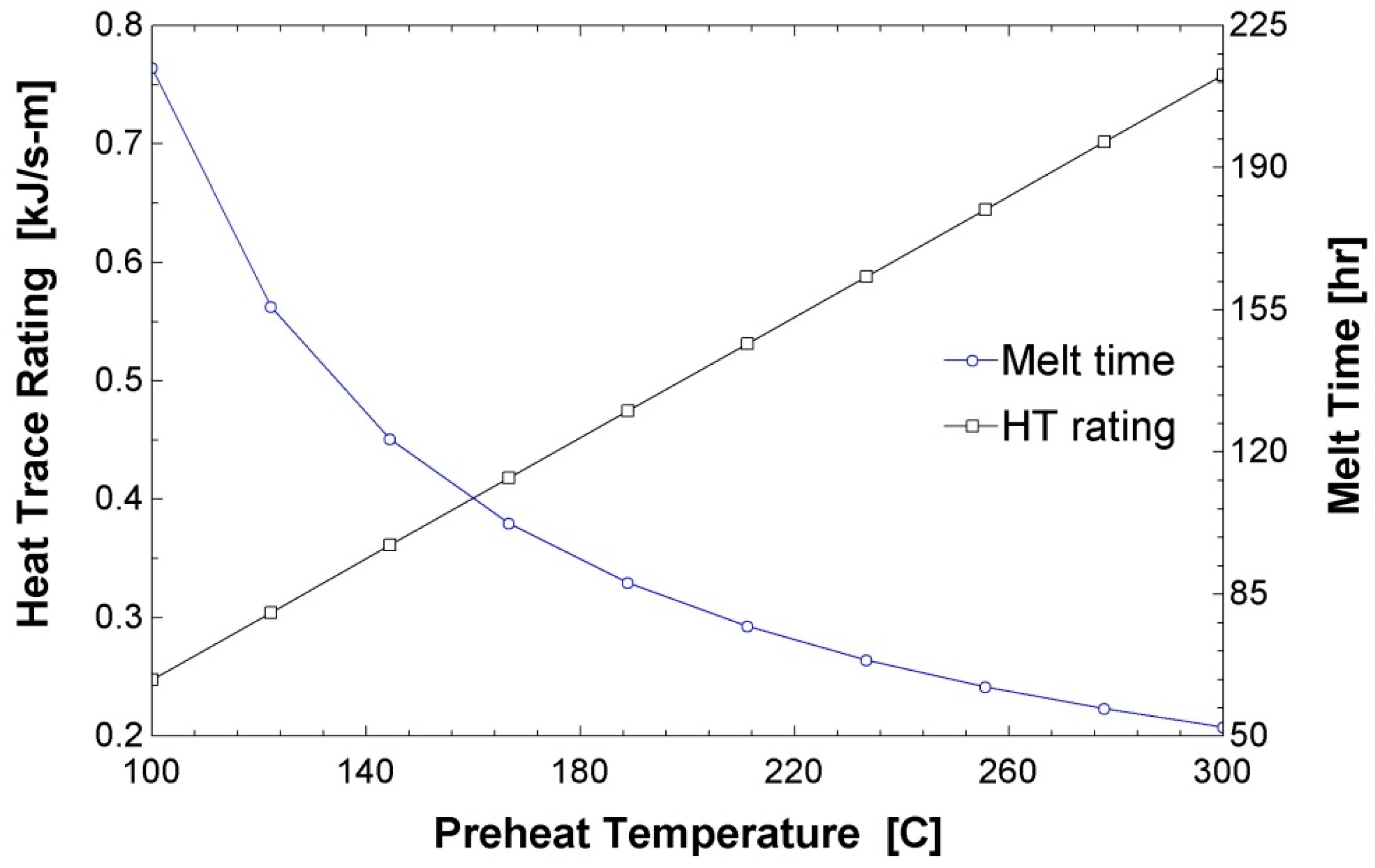
Figure 11 shows that because the model first sizes the system based on a user specified preheating time and then solves for melting transients, the melting rate is adversely affected by the initial preheating temperature that is specified per HTF. The system heat trace rating is proportional to the specified preheating temperature per each HTF, where the system melting performance drops off significantly as the specified preheating temperature is decreased.
The model has been integrated with the preliminary field pipe sizing model to generate the total heat trace system required for a molten salt HTF plant. The total model generates the optimal diameters for each pipe segment. Then, using a subprogram, the number of heat trace cables is calculated for each segment to satisfy the preheating requirements. The largest available heat trace cables output 0.05 W/m at their maximum operation. Since the code generates the required heating in W/m as well, it is a division criterion to arrive at the total number of heat trace cables for any pipe section. Multiplying by the length of each segment, we arrive at the total length of heat trace cable required in the plant, where redundant heat trace cables are added to the system to allow for fast recovery from failed heat trace cables. Redundant cables are calculated so that there are always at least 50% more cables then necessary. If the number of cables on the pipe is less than four, then two redundant cables are added. The redundant cables are not wired and are only connected if a cable on the same pipe fails. The total number of cables, redundant and wired, can be used to generate the total heat trace system cost.
The results in
Table 2,
Table 3,
Table 4 and
Table 5 show that HiTec and Solar Salt both require 141,892 m of heat trace cable, while HiTec XL requires 143,592 m. The values for HiTec and Solar Salt are the same because the heat trace cables come in discrete numbers and rounding causes the slight difference in required power to be lost. HiTec XL heat trace system requirements are larger because the pipe sizes for a HiTec XL based system were found to be slightly larger than the other two salts. Heat trace system sizes are a function of the pipe sizes and the HTF properties, but, because pipe sizes are only a function of HTF properties, the heat trace system size can also be considered a function of HTF properties.
4.2. Results and Discussion for the Impedance System
What is most significant to the sizing of an impedance heating system is its performance in off design conditions, such as during the night or in times of low solar irradiation.
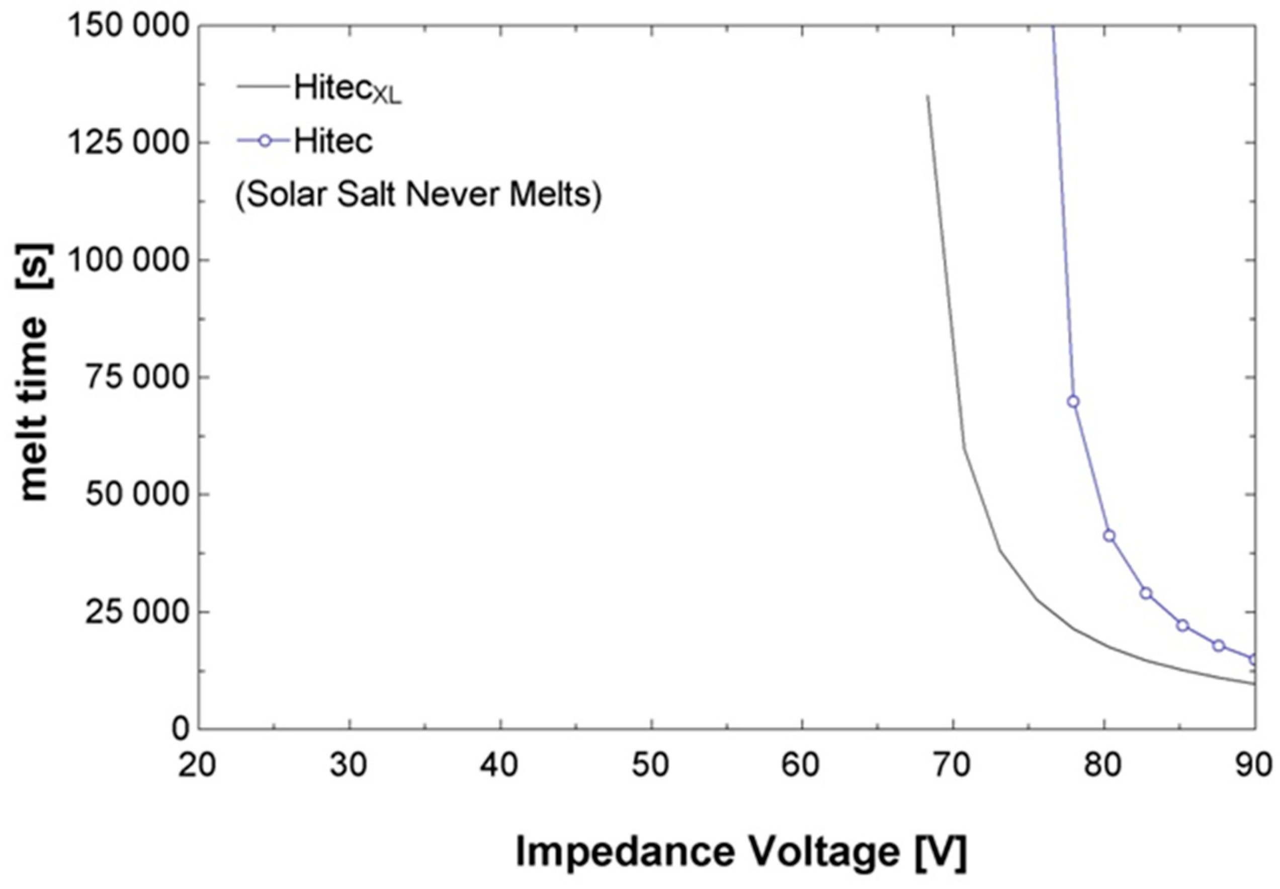
Figure 12 shows the melting time at different impedance voltages for a nominal system. An asymptotic behaviour is seen, where the salt is not able to be melted until a certain voltage threshold is reached. The effect of the high melting temperature of Solar Salt is observed on its ability to be melted. A much higher impedance voltage is needed to overcome the higher levels of heat loss due to the higher required melting temperature.
Figure 13 shows the melting time for a system with a compromised vacuum. Very high voltages are necessary to melt HiTec or HiTec XL, and no voltage under 90 volts can overcome the heat loss. The IEEE Std 844-2000 (IEEE Recommended Practice for Electrical Impedance, Induction, and Skin Effect Heating of Pipelines and Vessels) standard voltage limit of 80 volts hinders meeting this standard while still melting any of the salt options. This suggests that multiple transformers may be needed per solar collector assembly (SCA) to supply enough energy to cause melting.
Tubes with no glazing were also studied, but no voltages were found that were capable of melting any of the salt options. For this reason, no graph is presented.
The effect of wind speed on melting time was also considered. However, it was found that wind speeds of even 15 m/s had little (less the 5%) effect on the melting time. For the nominal tube, melting is possible for any operational wind condition. For a tube with broken or no glazing, melting is difficult or impossible without solar radiation.
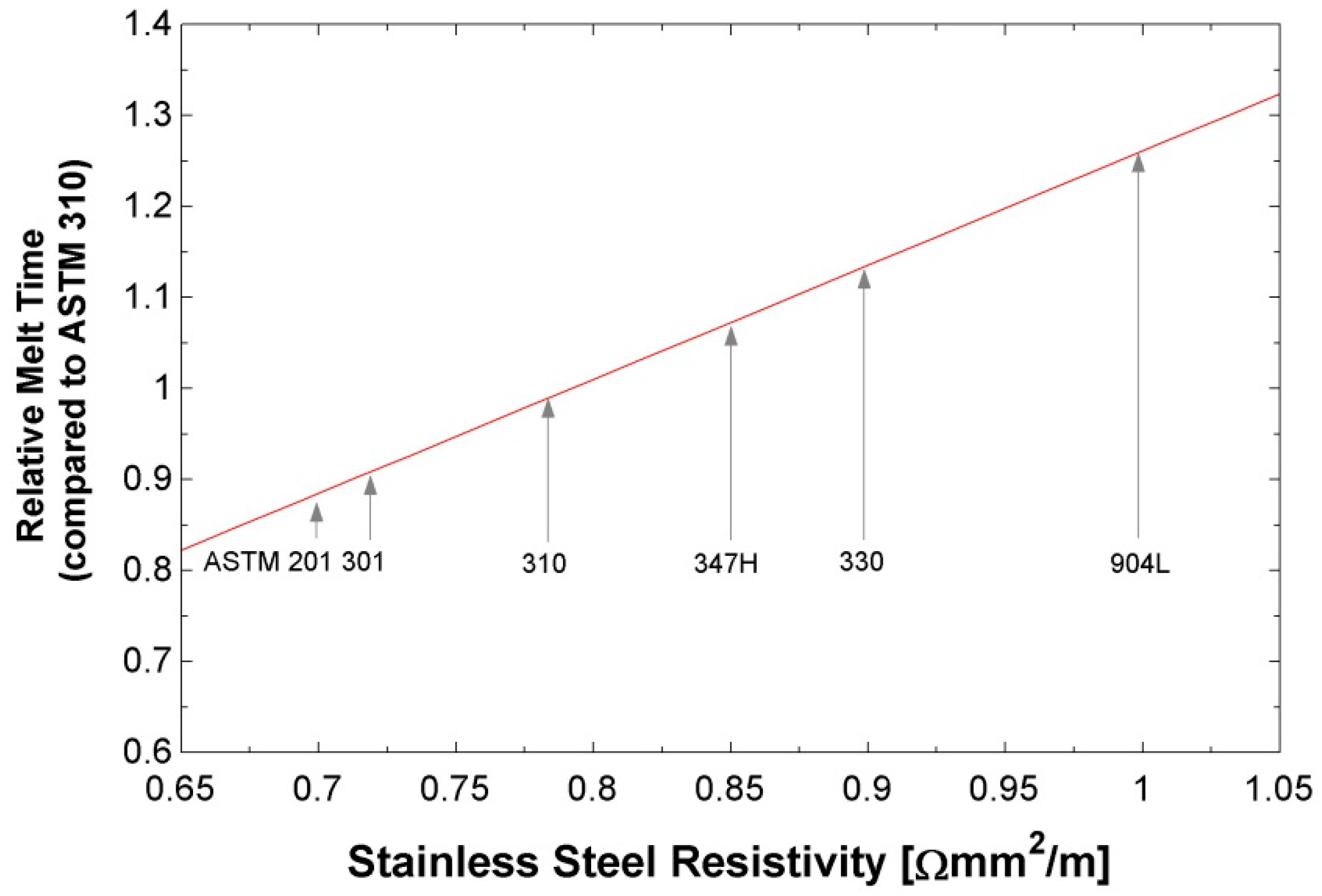
The material of the absorber was also analysed in this study. Currently ASTM 310 stainless steel is proposed. This material offers an appropriate resistivity value, but it could be improved. Since impedance heating is dependent on the square of current to determine power, materials with lower resistivities tend to perform better as heat generators. An analogy is shown below to help understand this trend. Given a large battery with two terminals, if the terminals are connected by something with high resistivity, like wood or plastic, no heat is generated. However, if the cables are connected to a material with low resistivity like copper, the wire will glow and generate large amounts of heat.
Figure 14 shows the melting time relative to the current system configurations for various stainless steel types. A 10–15% decrease in the melting time can be achieved by switching to 201 or 301 stainless steel. While this is an improvement, this change does not improve the overall situation significantly.
The goal of the model development was to design the system necessary to supply adequate impedance heating to recover from a freeze event. To do this, an operational target was developed. The metrics used in the target are summarized in
Table 6.
One day was chosen as a melting time as a standard time from a commercial plant. Lost vacuum was chosen as the worst case because it is assumed that any collectors with broken envelopes would be repaired prior to melting. On the other hand, lost vacuums are not easy to diagnose and are often only replaced at infrequent intervals. Therefore, during a freeze event, some tubes with lost vacuums would need to be melted.
Impedance heating provides a constant heat input along the entire length of the pipe. Furthermore, axial thermal conduction in the pipe and salt is minimal. This allows for each heat collection element (HCE) to be modelled as an island. That is, a HCE with no vacuum will melt at the same rate, no matter whether it is surrounded by tubes with vacuums intact, with no vacuum, or with no glazing. We assume that in every loop there will be at least one HCE with no vacuum, constraining our melting time to the melting time of an HCE with no vacuum.
A system using each salt was analysed for two electrical configurations: One transformer per SCA and two transformers per SCA. For the one transformer setup a connection cable length of 80 m was used. For the two-transformer setup 40 m was used.
Figure 15 shows a design layout for a system with one transformer per SCA. The cable lengths are shown with the arrow tipped lines going to and from the transformer. The necessary voltage to reach the target conditions was calculated assuming no solar radiation. These results are tabulated in
Table 7. HiTec and Solar Salt systems will need to have two transformers per SCA.
Finally, the total melting time of the system was investigated. It was not considered that the whole field is melted simultaneously, so as not to penalize the cost of the transformers that feed the impedance currents. Different cases of loop simultaneity were considered. The number of loops capable of melting simultaneously was the parameter to optimize. Based on the cost of the DC conductor necessary to feed each loop and the complexity of the utility of switching the plant from a 240 MW source to a 150 MW sink, the actual number was estimated to be around 10. This results in total plant melting times from 100 to 300 days. This represents a significant financial penalty for freezing.
5. Conclusions
Parabolic trough collector (PTC) technology with thermal oil as the HTF is currently the most mature solar technology that is implemented at commercial scale. The use of molten salts as HTF has the advantage of being able to work at higher temperature to increase plant efficiency, and the disadvantage of the potential freezing of the HTF in pipes and components. Two methods of freeze recovery needed in this design have been developed to evaluate the technical feasibility of molten salt in PTC systems. A model of heat tracing in pipes and components, and a model of impedance melting in the solar field has been developed in this paper to compare the freezing protection system in three molten salts mixtures, namely Solar Salts, Hitec and Hitec XL.
In the heat tracing model, all piping included in the heat trace system was heated using a mineral insulted (MI) cable. This is the only type of heat trace cable that can withstand exposure temperatures over 250 °C. Mineral wool thermal insulation with an aluminium jacket was used on all traced piping. Mineral wool insulation was used on valve bodies and bonnets with removable blankets on the actuators. The heat tracing model has been created to size the heat tracing system for any pipe. In addition, the model has been applied to the overall pipe sizing and costing model to make future system cost estimations more accurate.
The model has evaluated the recovery after a freezing event, obtaining that the melting times are acceptable for all pipe diameters proposed in the study. The result of the model also shows how HiTec salt requires less heat trace power in its operation. When evaluating the three fluids, it is concluded that the recovery from freezing in a molten salt plant is possible. The threat of system wide HTF freeze events does not invalidate the concept of molten salt HTFs.
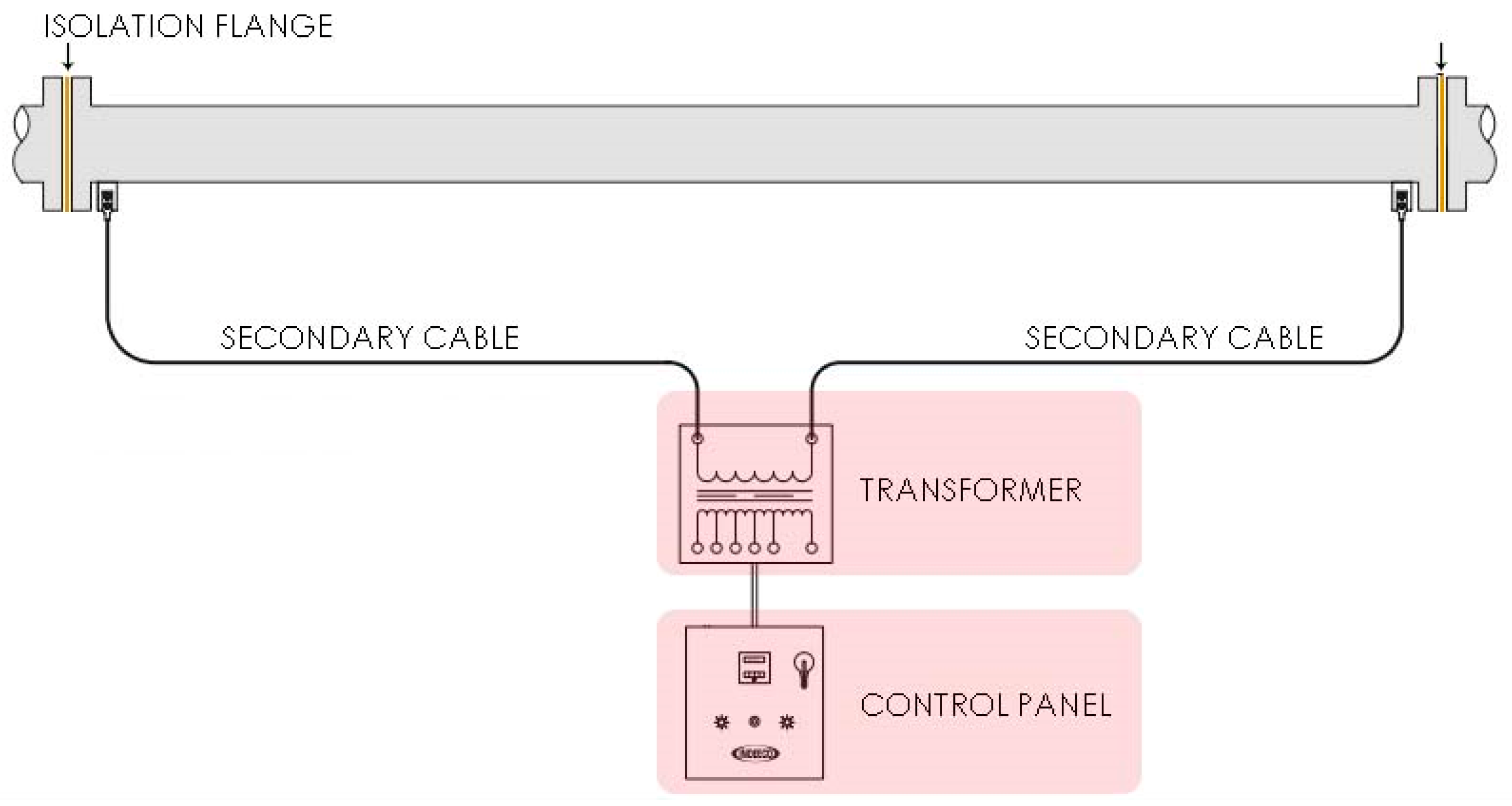
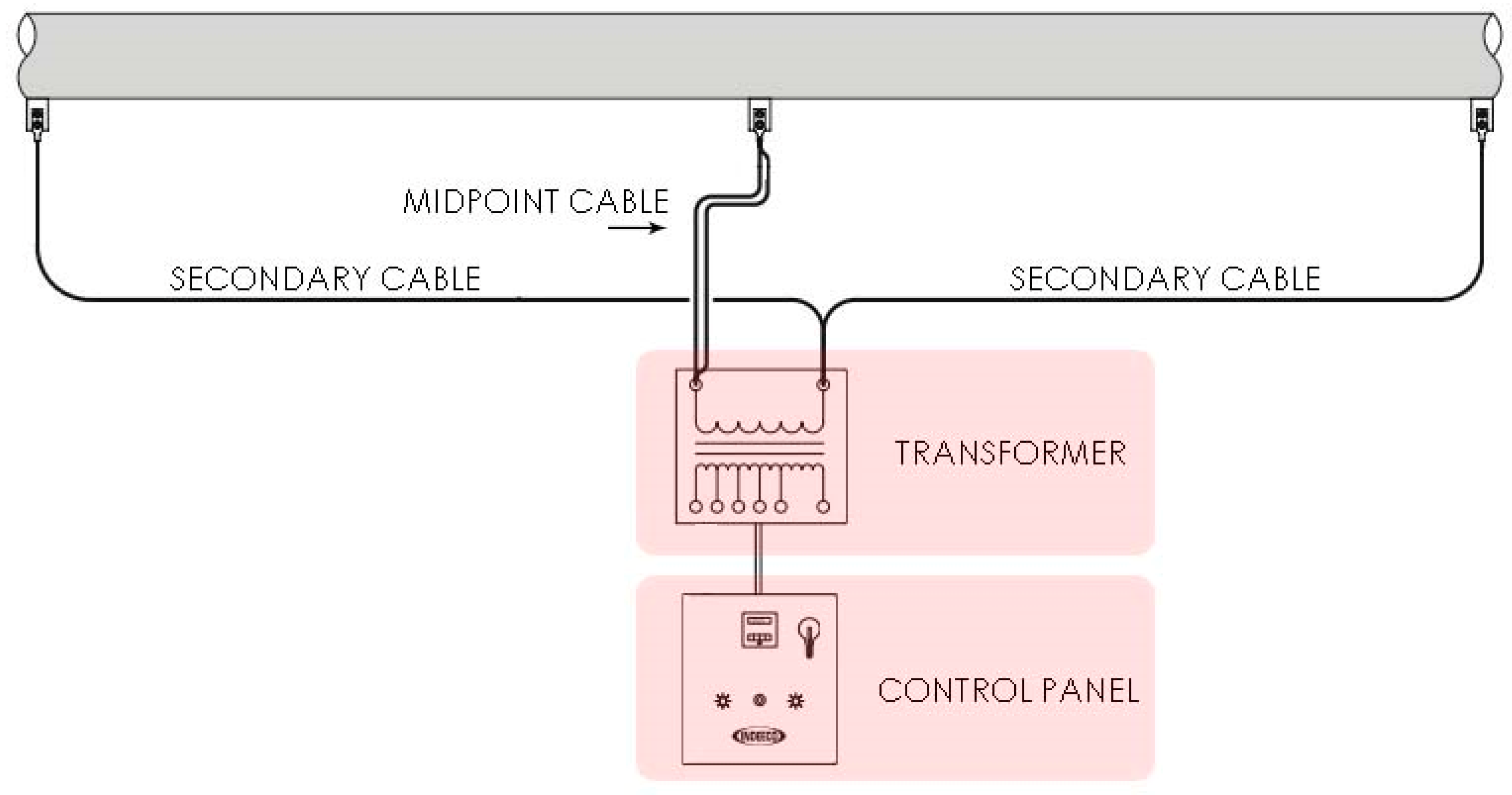
In the impedance model, the receiver tubes were heated with impedance heating, which consisted of a standalone panel and transformer for each collector. Each impedance heating system was a mid-point system to avoid the need for electrical isolation between the receiver tubes and adjacent piping.
The impedance heating model has analysed the performance under off-design conditions (tubes with lost vacuum and high wind losses), showing the increase in the melting time for tubes with a compromised vacuum. This requires working with two SCA transformers for HiTec and Solar Salt. Additionally, more than 100 days will be needed to completely melt a fully frozen solar field.
Even when the melting times involved are not ideal, the reliability of an impedance-based recovery system is high and, as such, freeze events do not stand in the way of future work on molten salt HTF systems.
The models developed show that both systems are technically feasible, since the plant may recover from a freezing event in all studied cases, although the recovery times considerably penalize the performance of the plant. Therefore, an economical detailed study including capital expenditure and operational expenditure (CAPEX and OPEX) is necessary to see which system is the best for a commercial plant.

 ,
, 


