Grid Synchronization of a Seven-Phase Wind Electric Generator Using d-q PLL


 ,
,  and
and 
Abstract
:1. Introduction
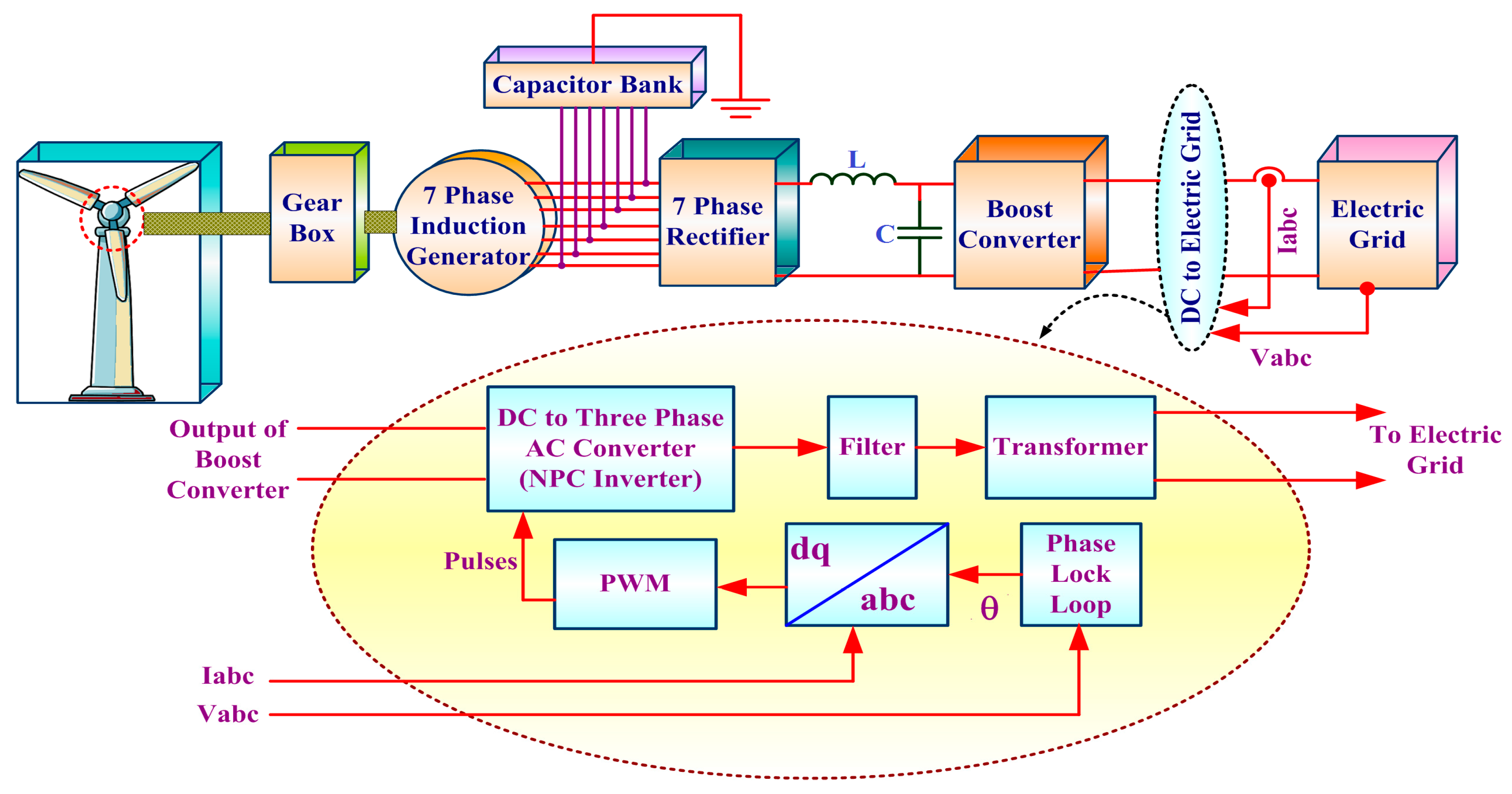
2. Proposed System Description
3. Modeling of System Components
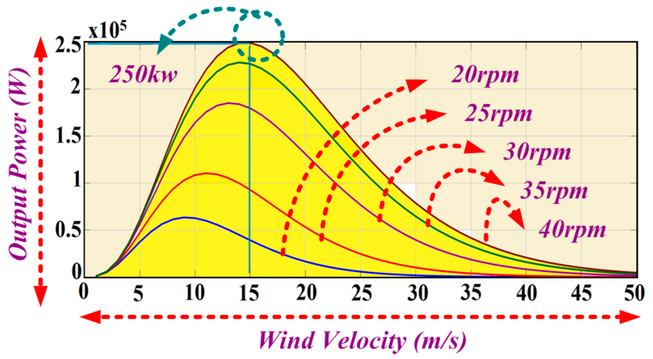
3.1. Wind Turbine
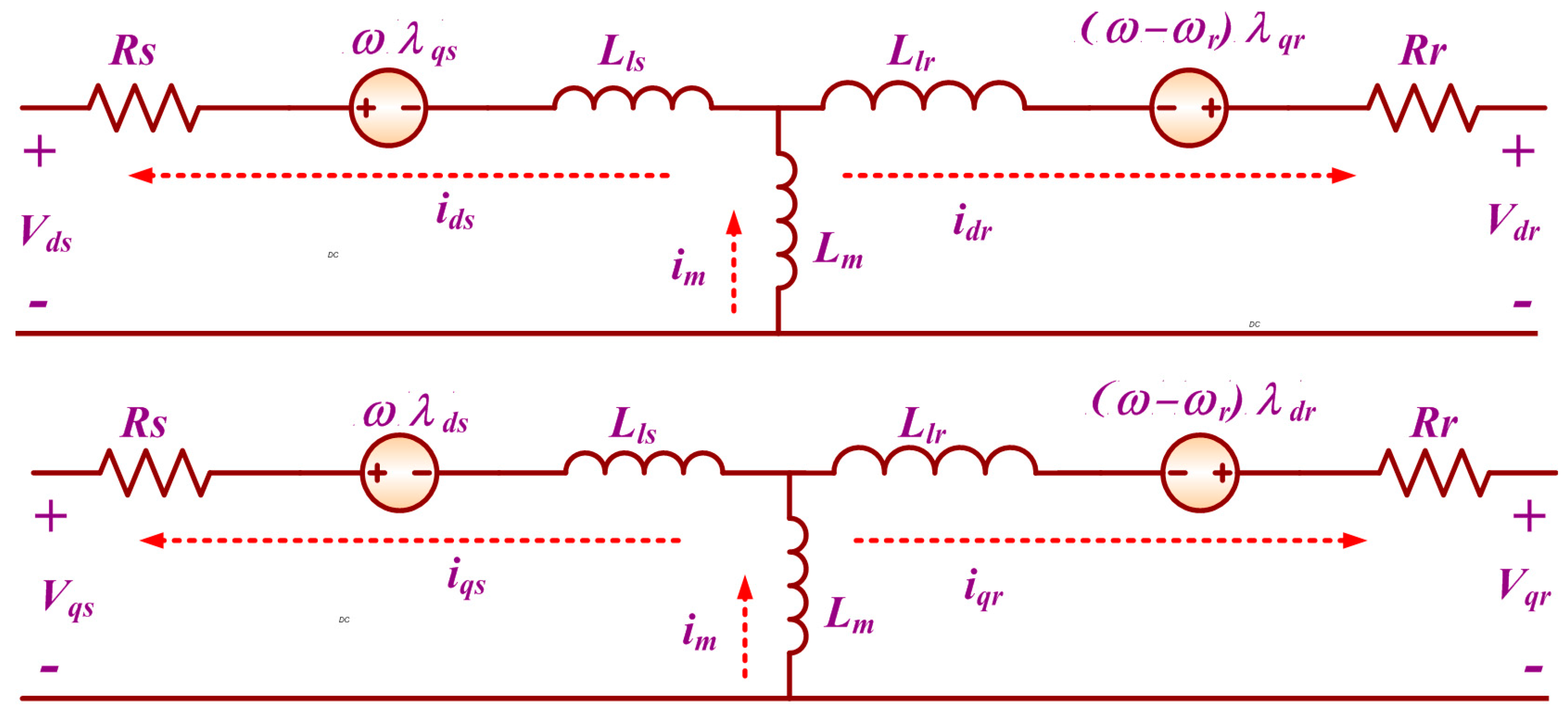
3.2. 7PIG Model
3.3. Modeling of the Shunt Capacitor and Load
4. DC Link Converter
4.1. Seven Phase Diode Bridge Rectifier
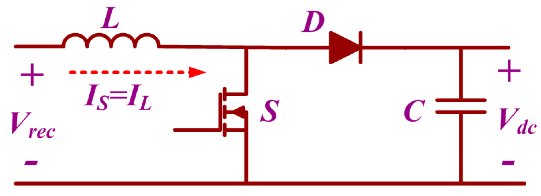
4.2. DC-DC Boost Converter
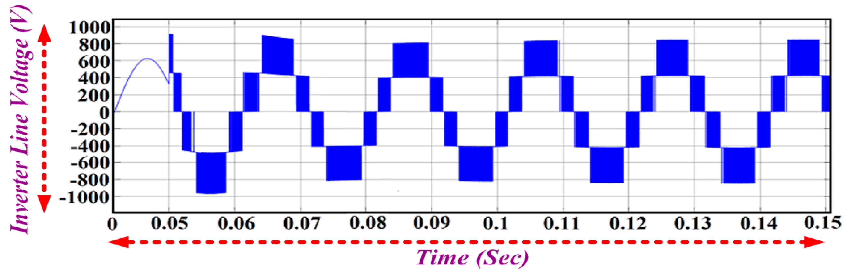
4.3. Three Level Neutral Point Clamped Inverter
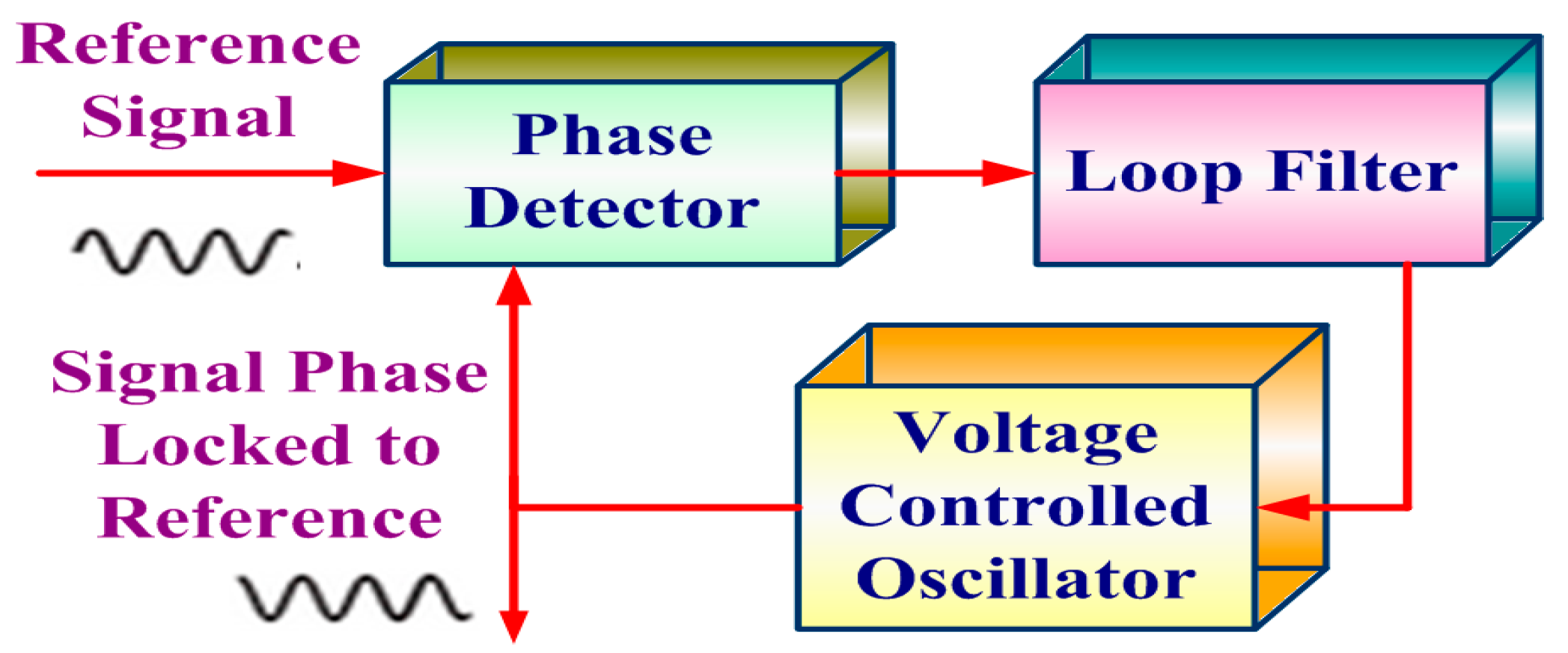
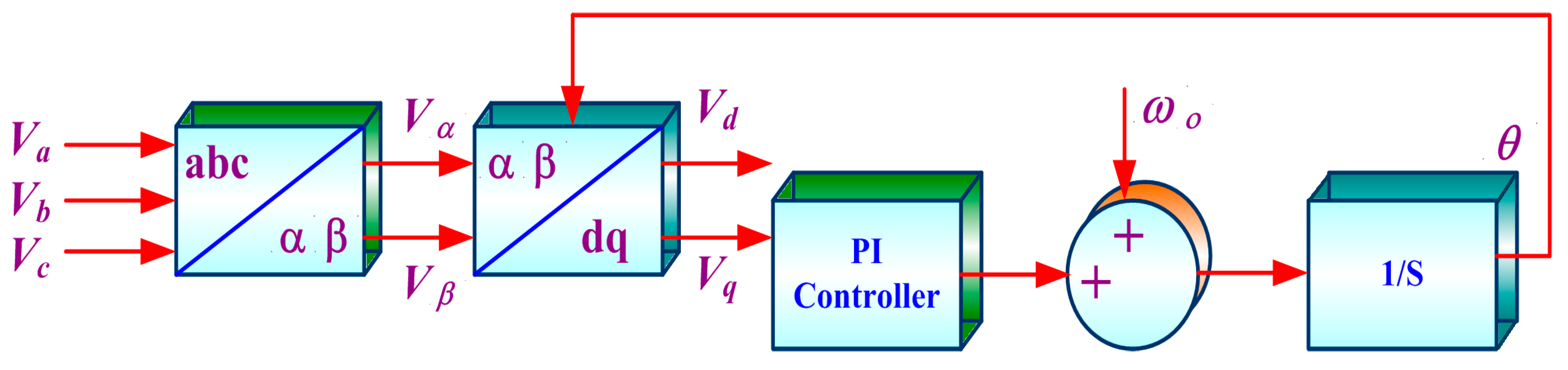
5. Grid Interface Using PLL
Synchronous Reference Frame (SRF/d-q) PLL
6. Simulation Result
6.1. Wind Turbine
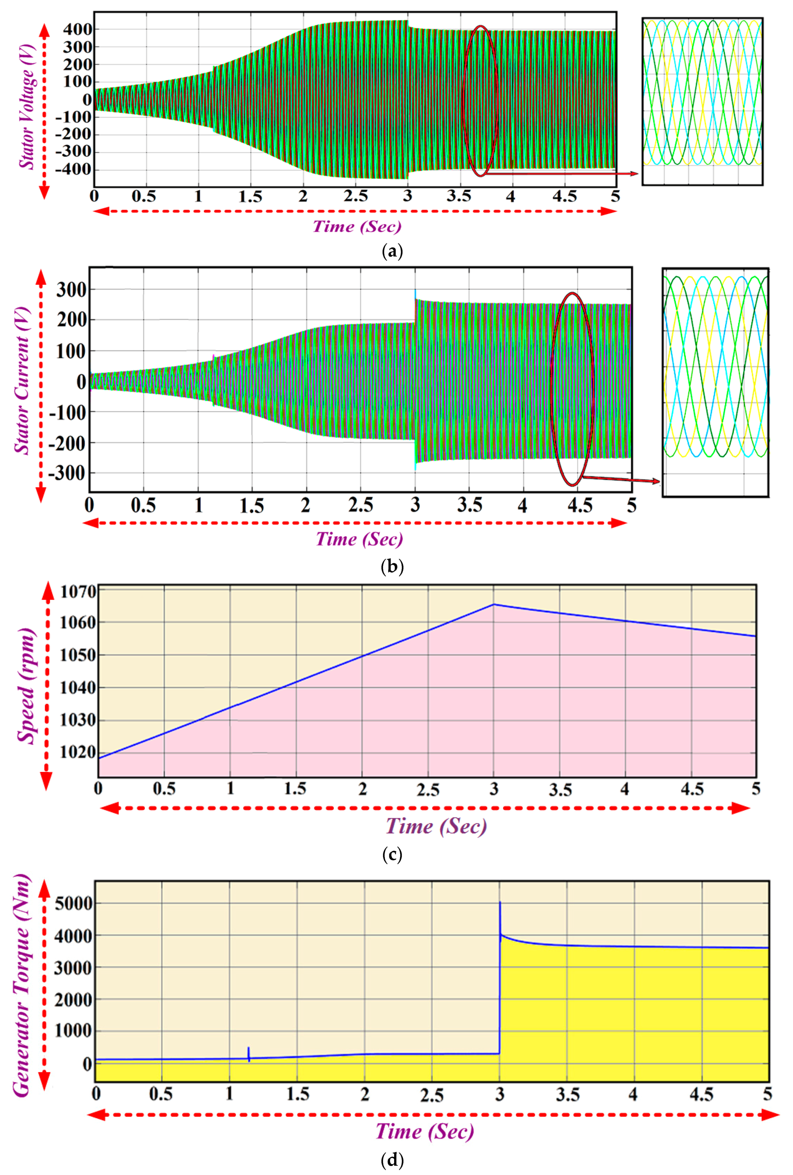
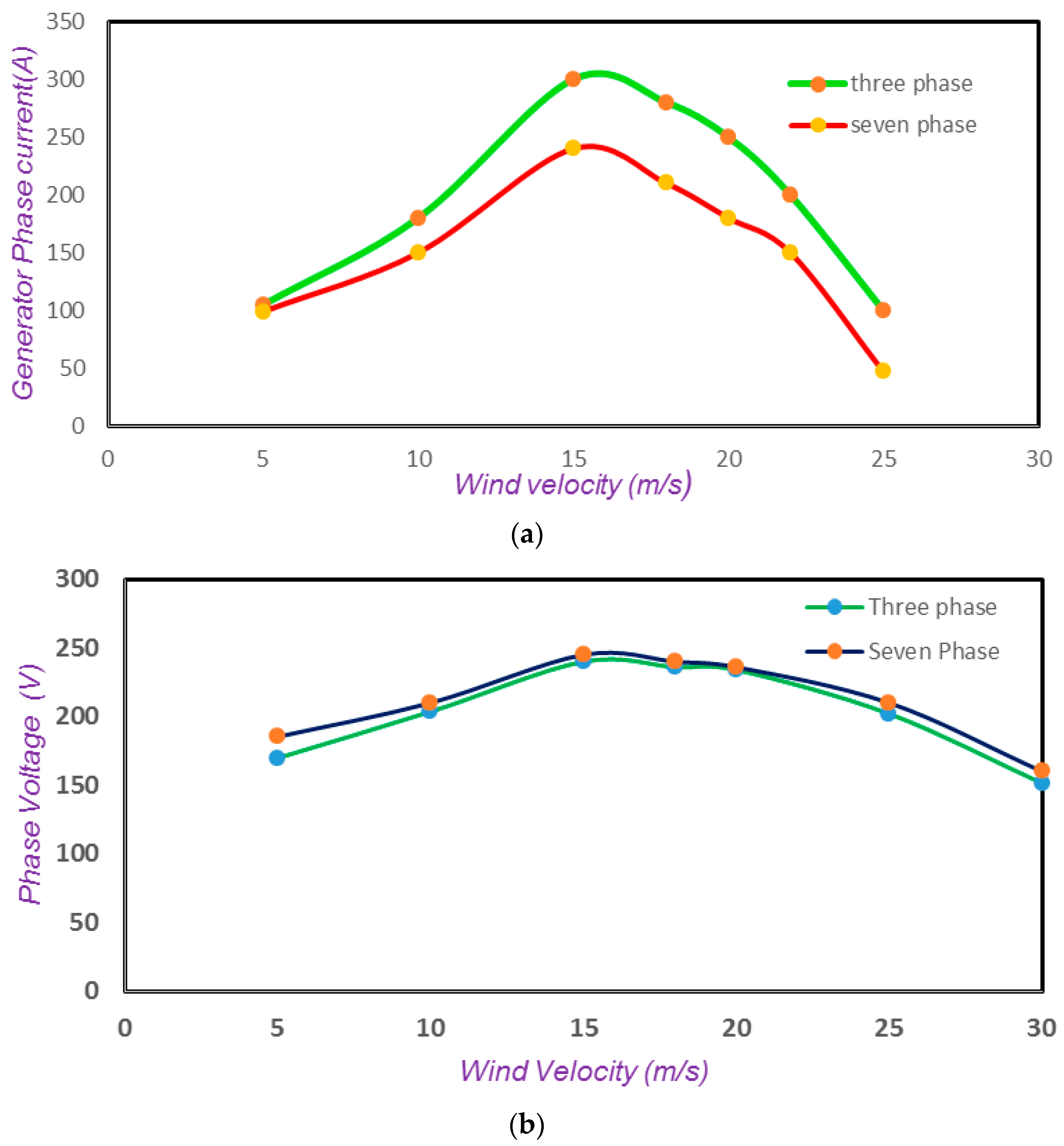
6.2. Seven Phase Induction Generator
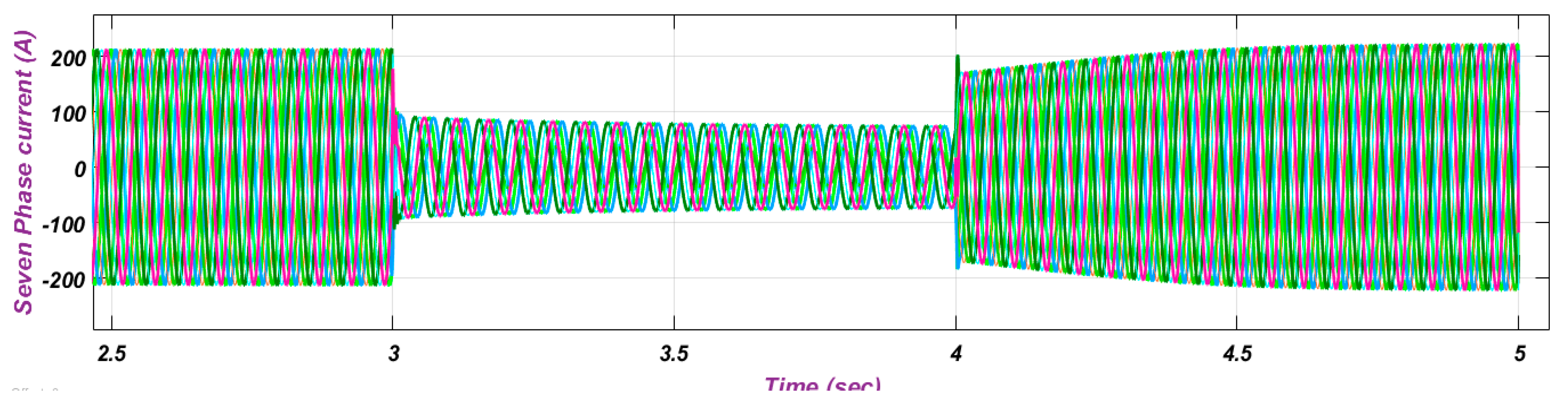
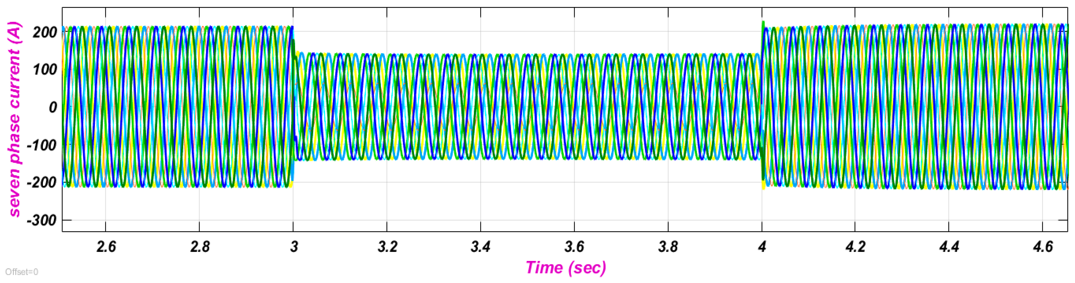
6.3. Fault Tolerant Operation of 7PIG
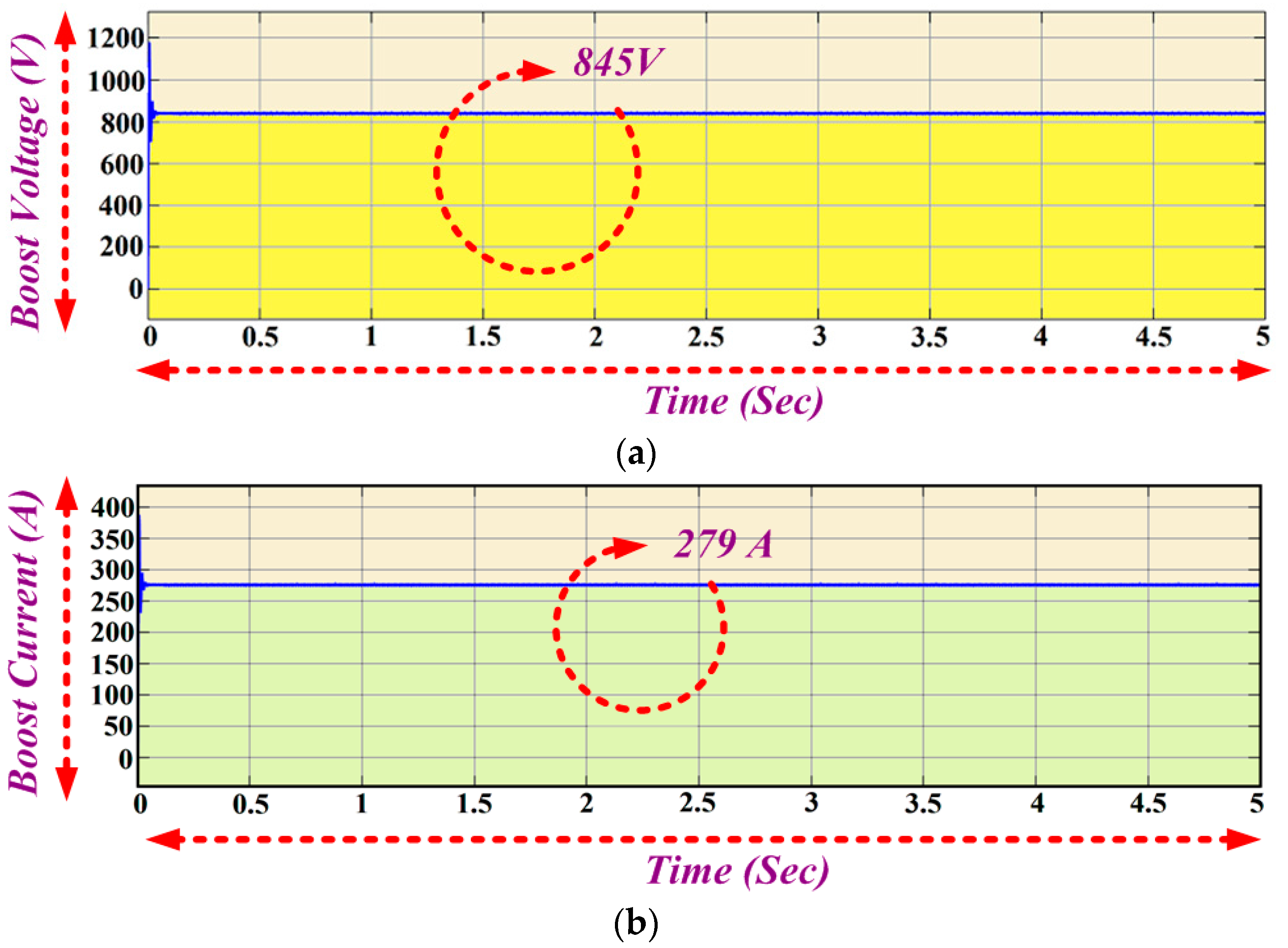
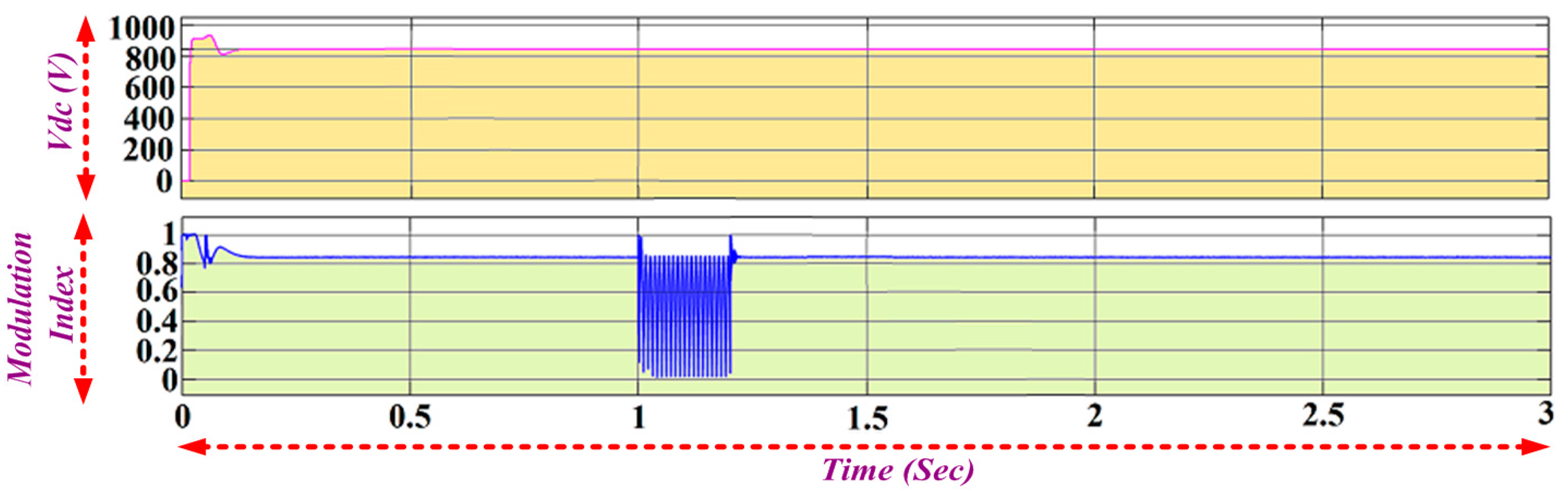
6.4. DC Link Converter
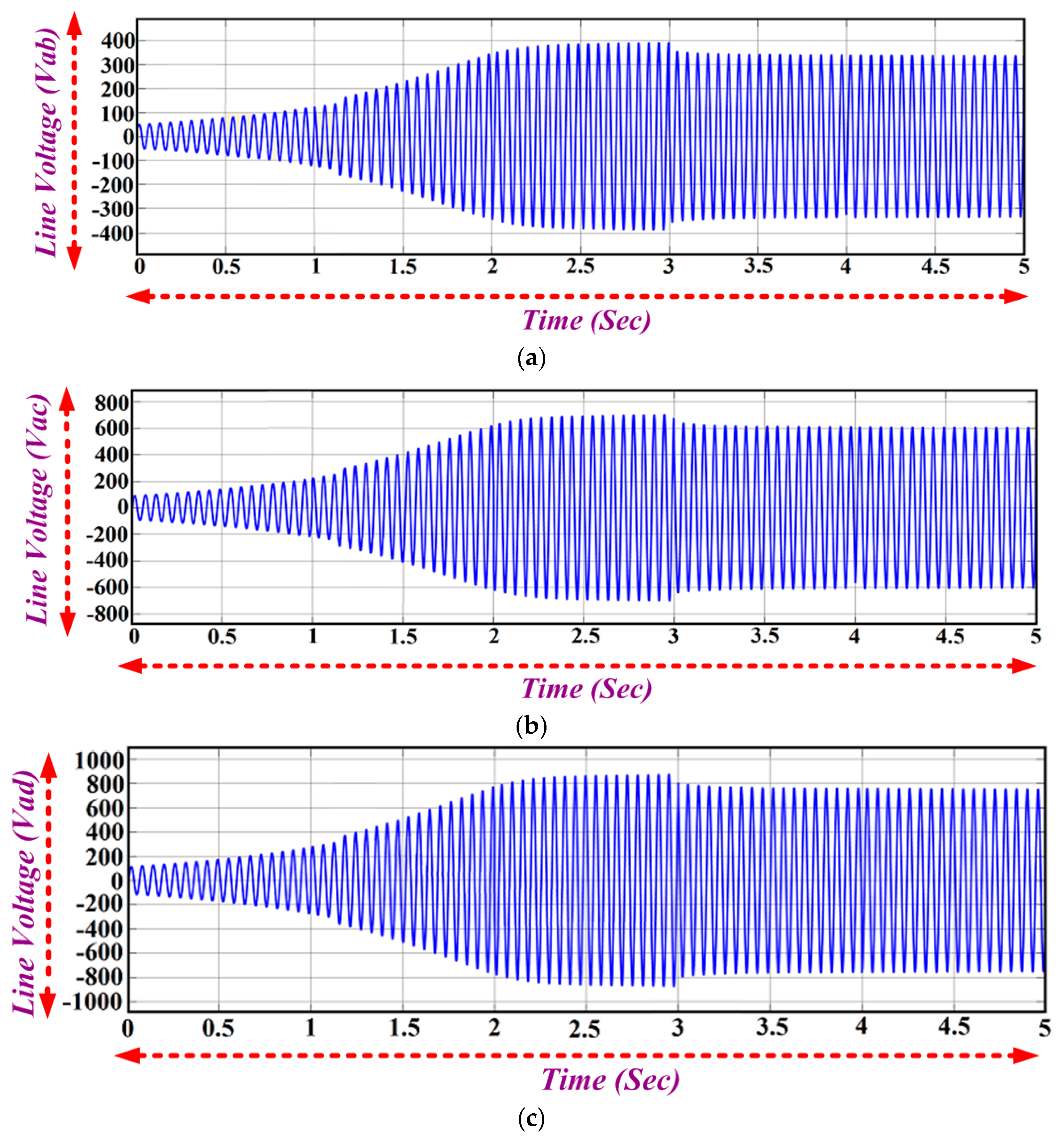
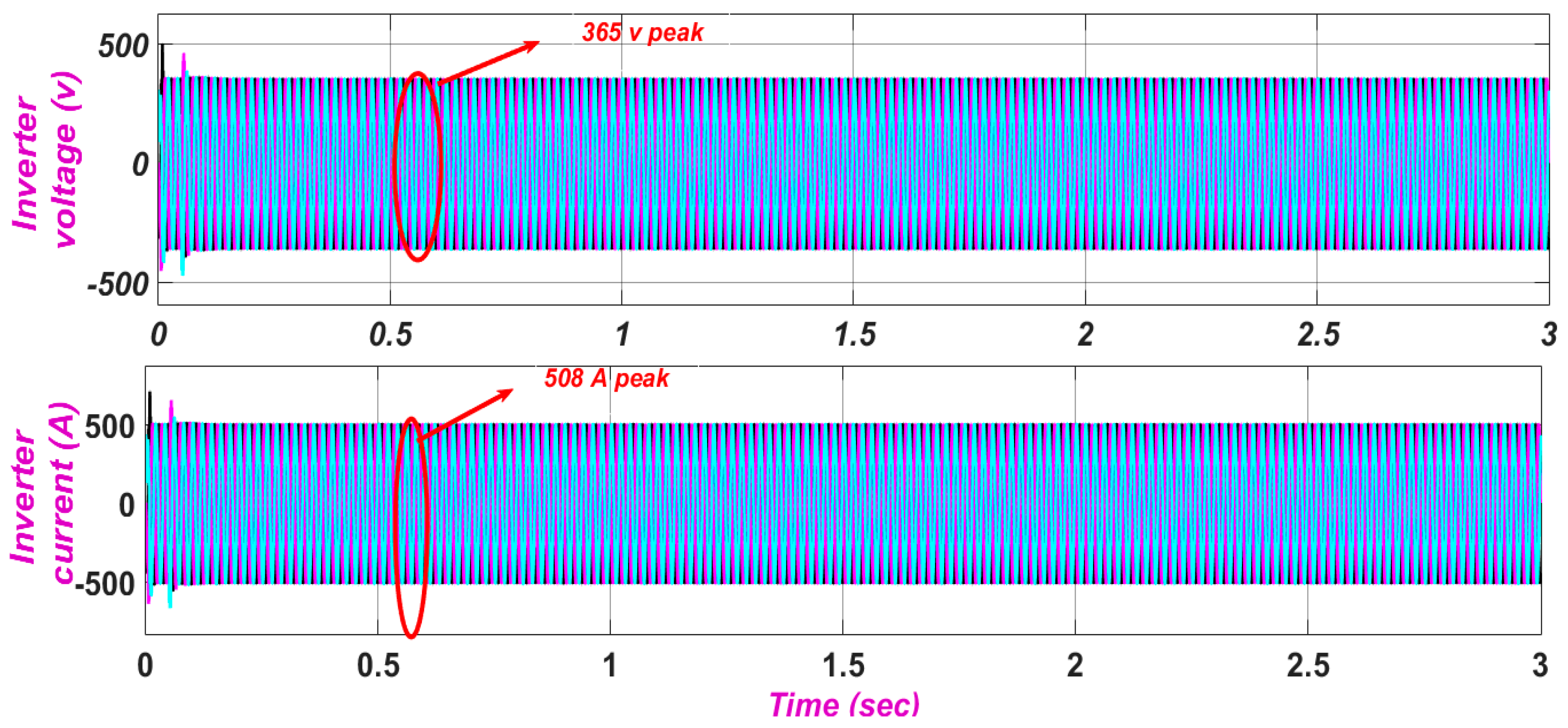
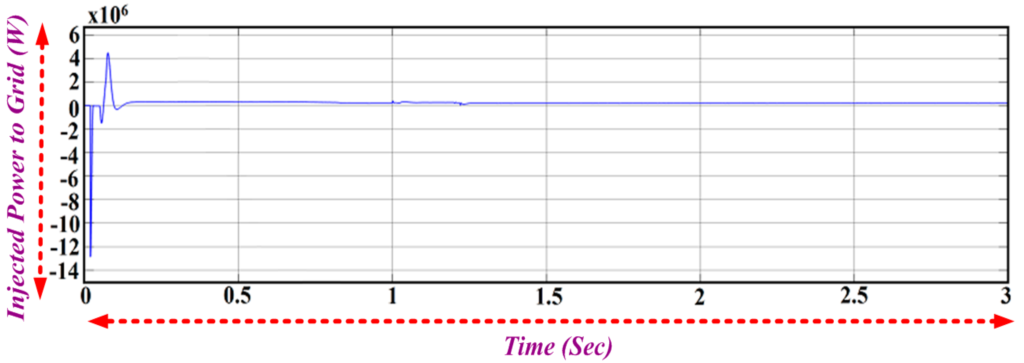
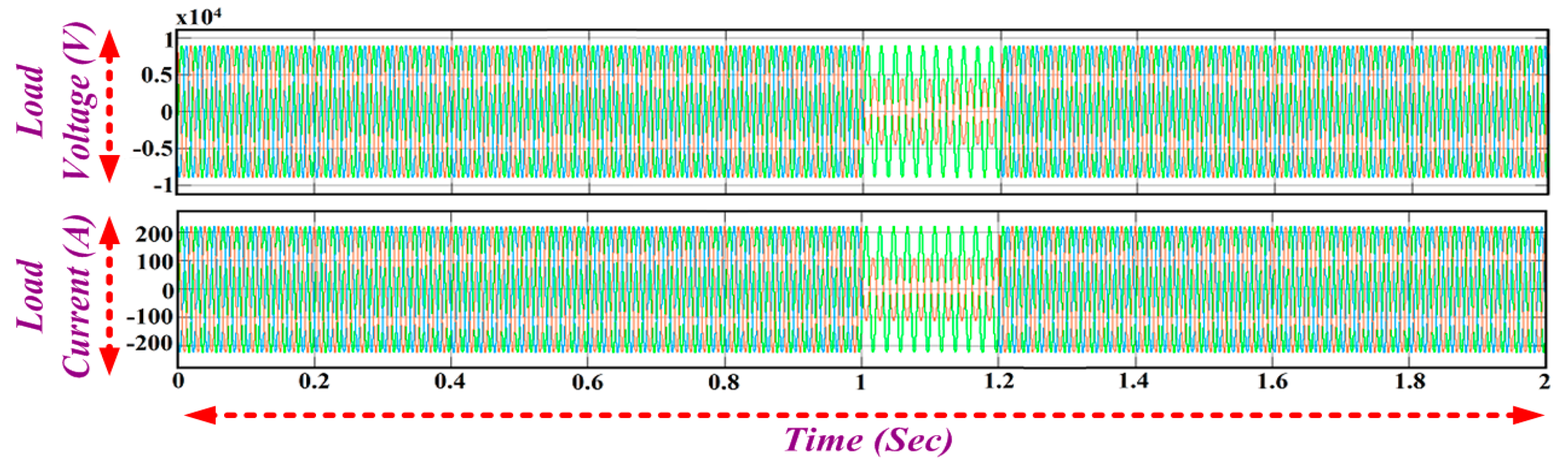
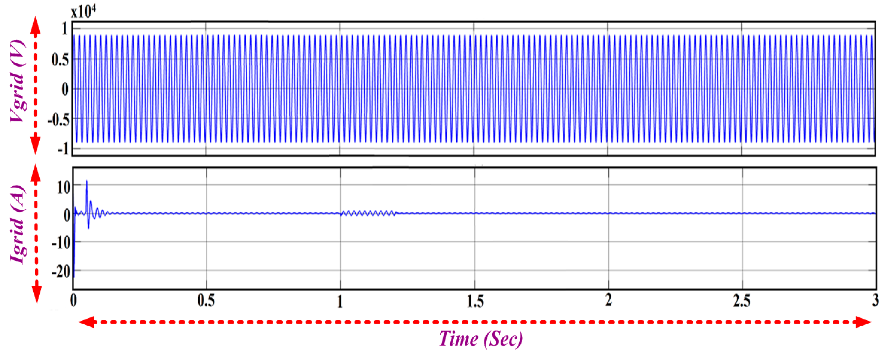
6.5. Grid Integration
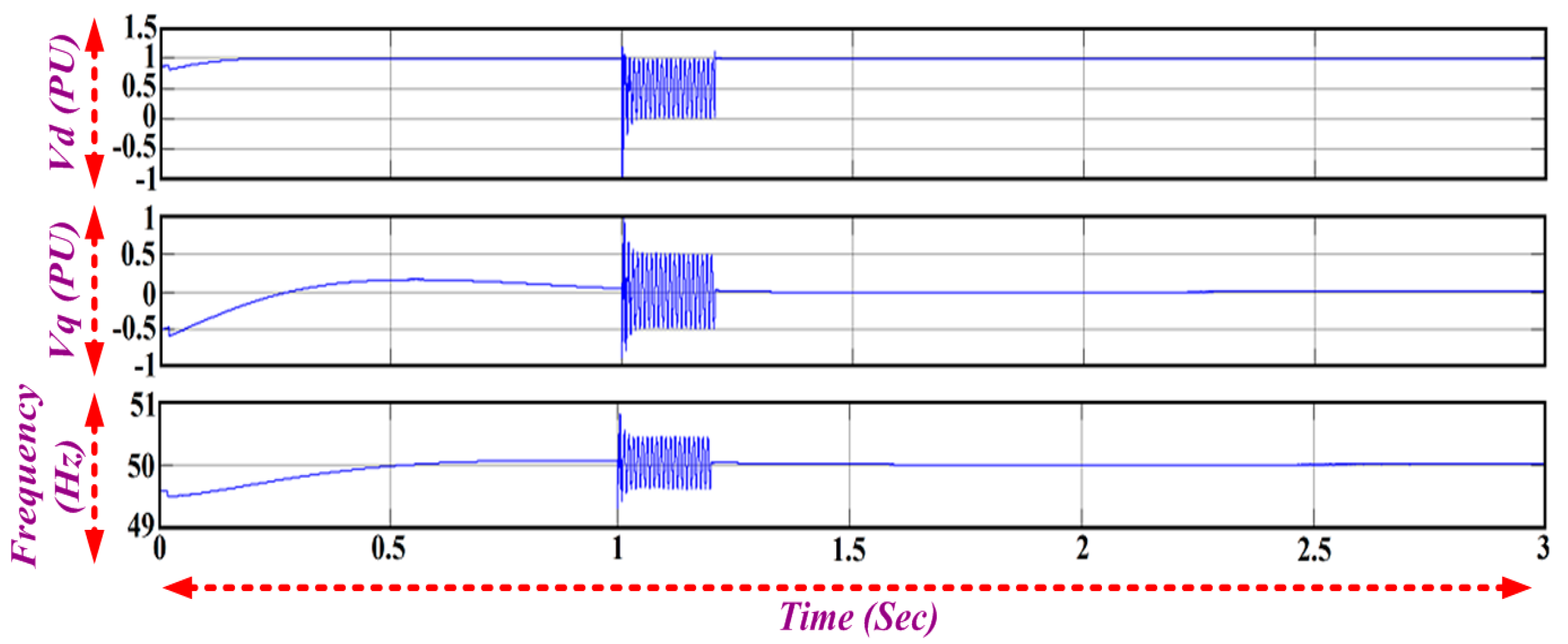
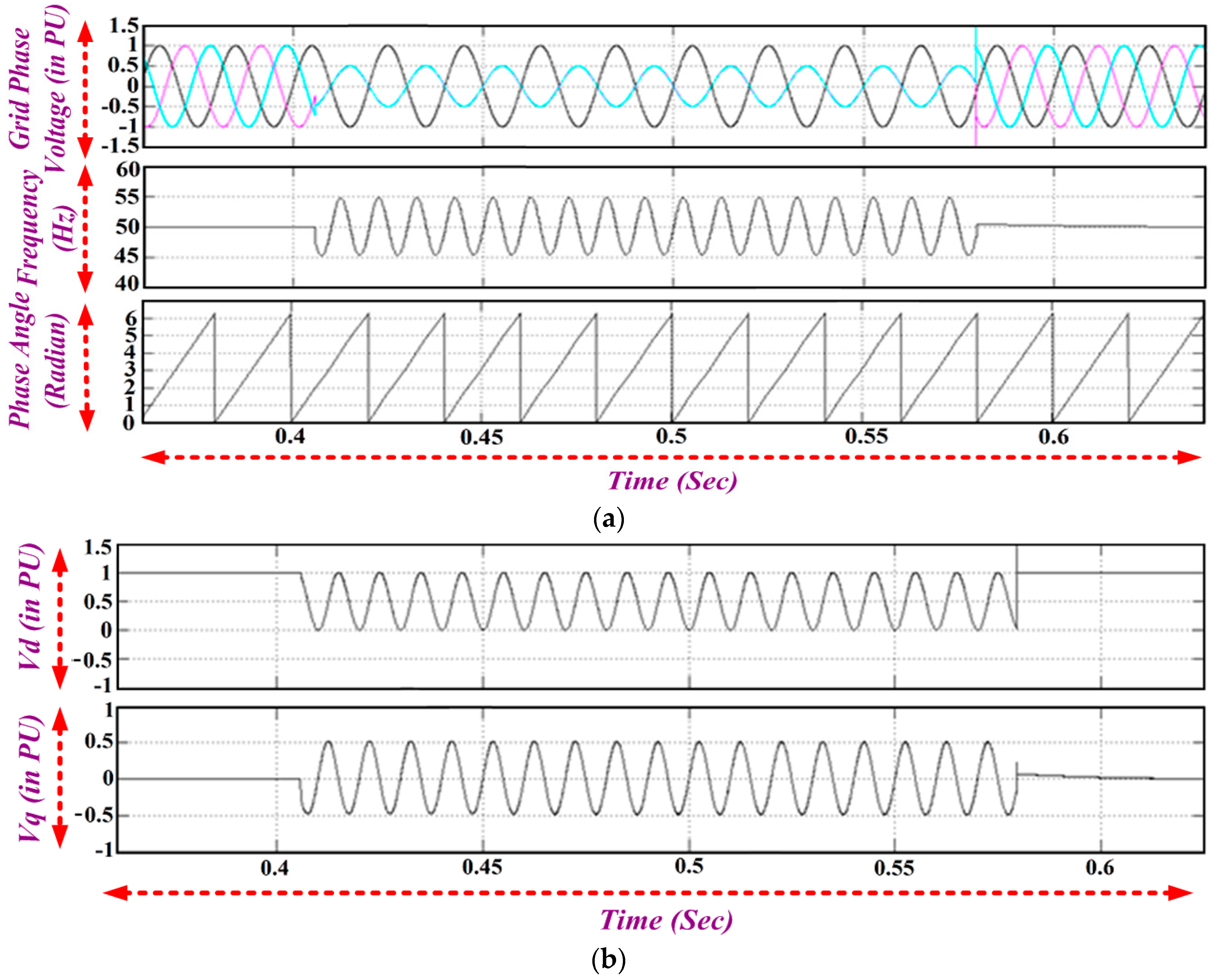
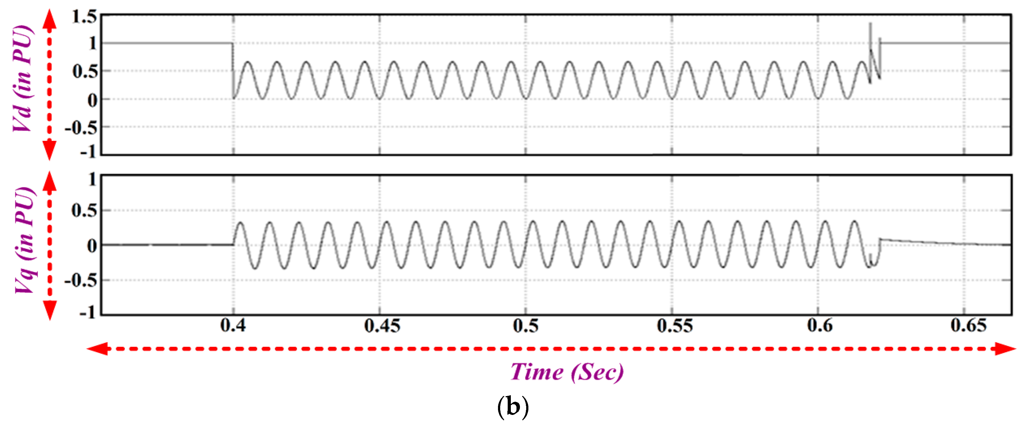
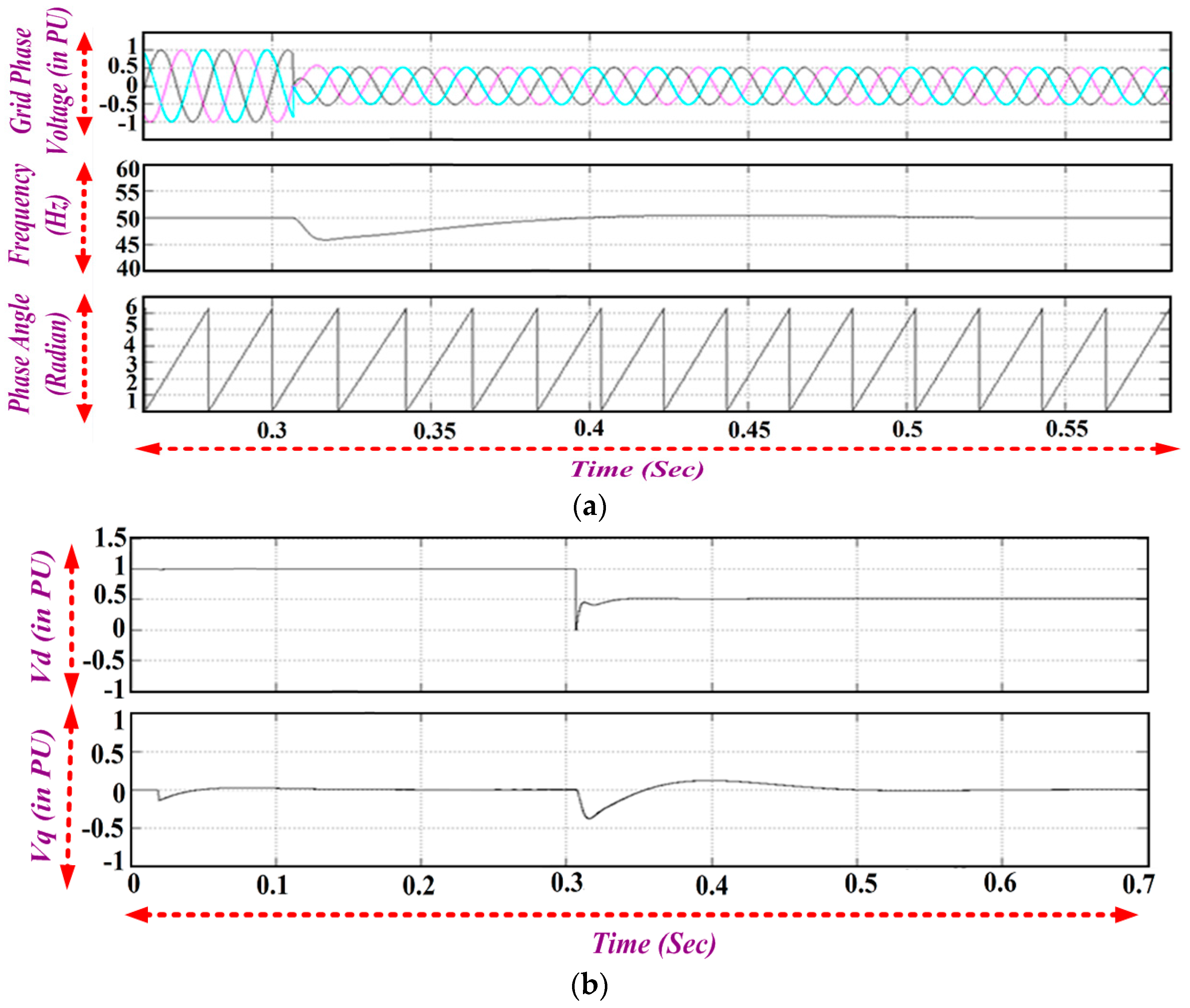
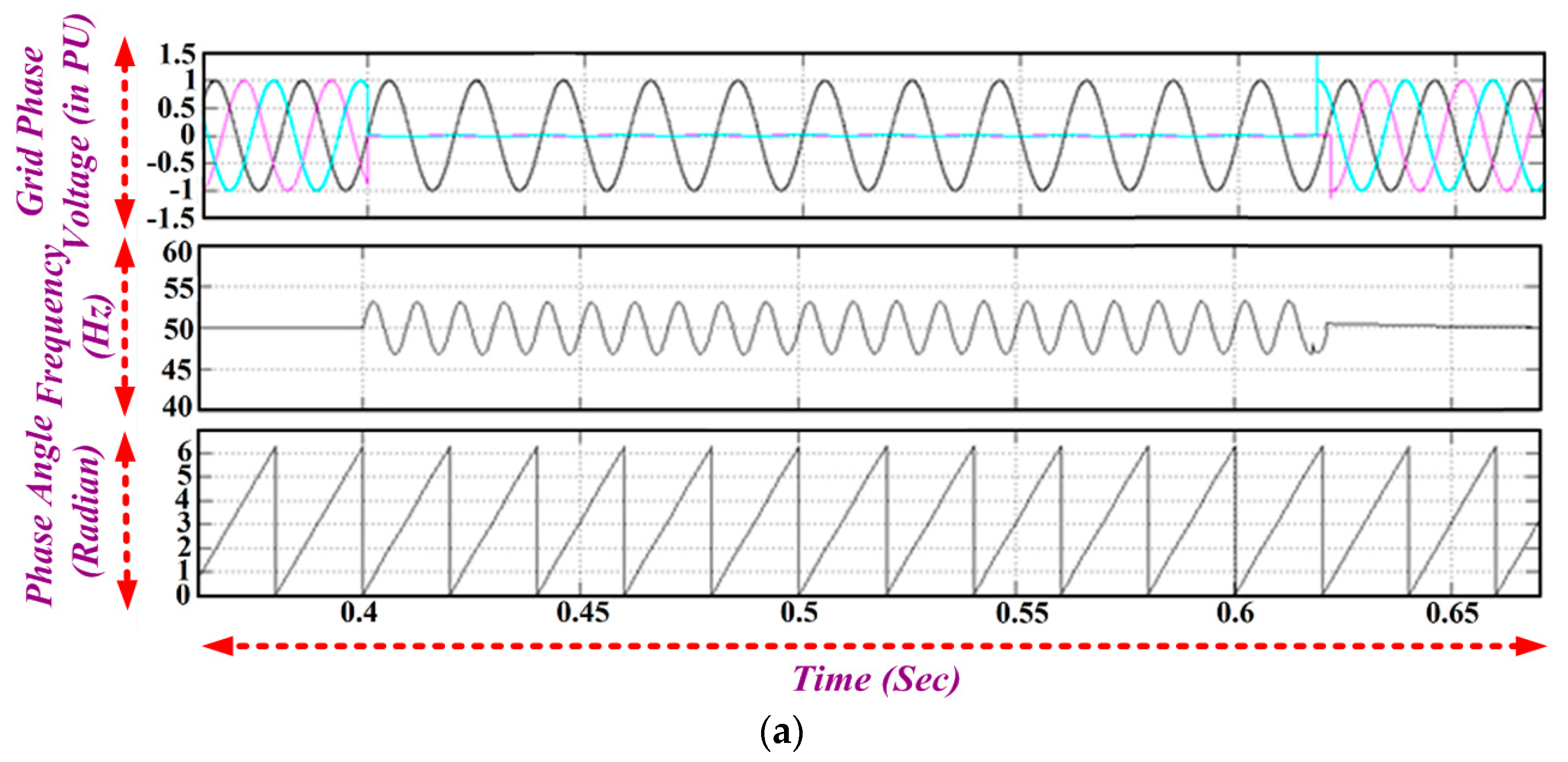
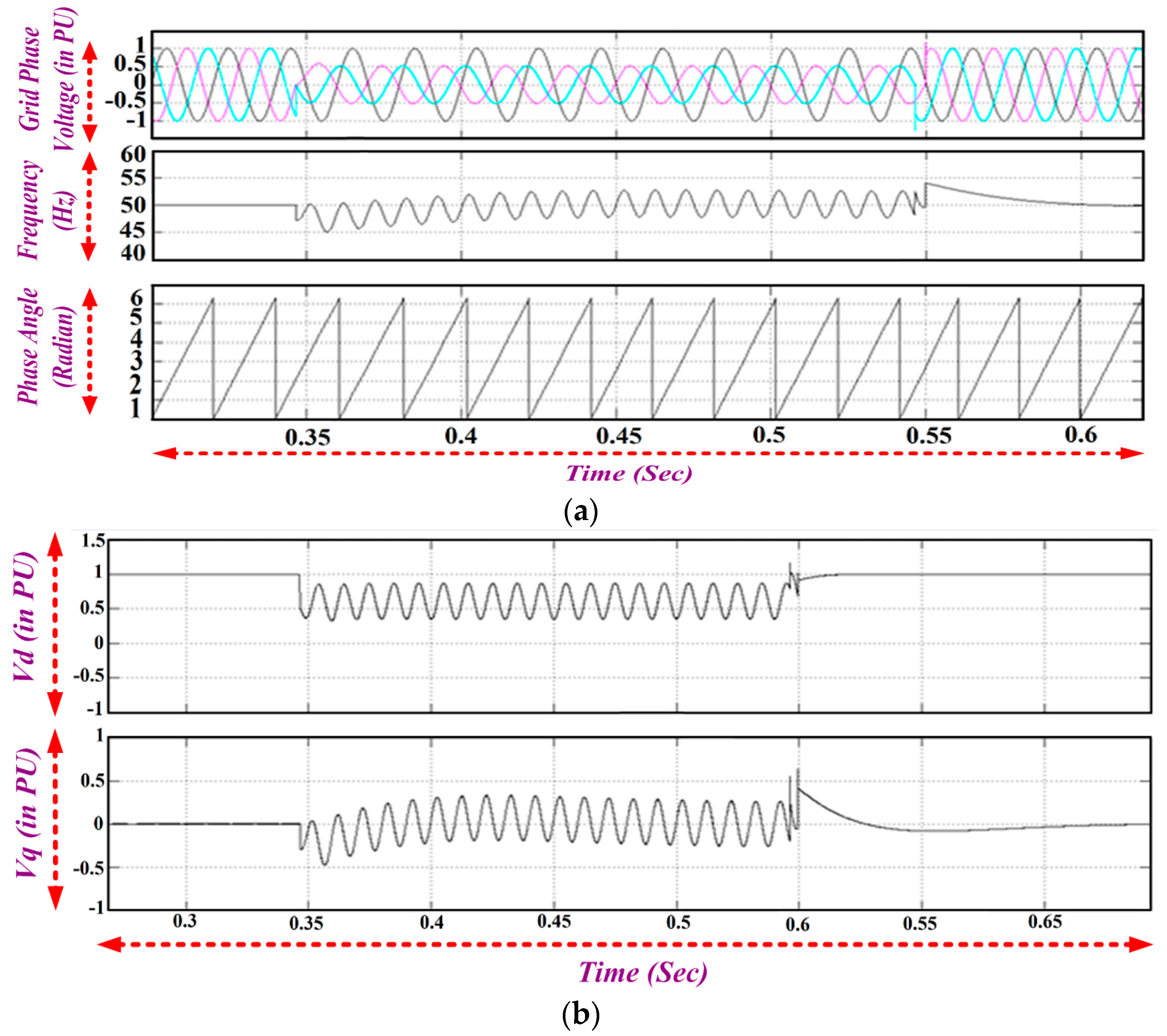
6.6. SRF PLL Performance under Various Grid Conditions
7. Conclusions
Acknowledgments
Author Contributions
Conflicts of Interest
Nomenclature
| MPIG | Multiphase Induction Generator |
| 7PIG | Seven Phase Induction Generator |
| WEG | Wind Electric Generator |
| d-q | Direct-Quadrature axis |
| Rs, Rr | Stator, Rotor resistance (Ω) |
| Ls, Lr | Stator. Rotor leakage inductance (mH) |
| Lm | Mutual inductance (mH) |
| ids, iqs | Stator d-q-axis currents (Amps) |
| idr, iqr | Rotor d-q-axis currents (Amps) |
| Vds, Vqs | Stator d-q-axis voltage (V) |
| Vdr, Vqr | Rotor d-q-axis voltage (V) |
| λds, λqs | Stator d-q-axis flux linkage |
| SRFPLL | Synchronous Reference Frame Phase Locked Loop |
| λdr, λqr | λqr Stator d-q-axis flux linkage |
| P | Numbers of poles |
| p | Differential operator with respect to t |
| ∆ | Tip Speed ratio |
| B | Blade Pitch Angle |
| ωtur | Angular speed of turbine |
| Tg | Electromagnetic Torque |
| fs | Switching frequency (Hz) |
| δ | Duty ratio |
| Vm | Peak value of phase voltage (V) |
| U,θ | Amplitude and phase of input |
Appendix A

| Wind Turbine | 7PIG | ||
|---|---|---|---|
| Rated power | 250 kW | Rated power | 210 kW |
| No. of blades | 3 | Rated voltage | 240 V |
| Rated speed | 40 rpm | Rated current | 240 A |
| Rotor Diameter | 29.8 m | Rated frequency | 50 Hz |
| Air density | 1.2 kg/m3 | Rated power factor | 0.82 |
| Blade pitch angle | −1.1 | Rated speed | 1018 rpm |
| Gear Ratio | 1:24.52 | No. of poles | 6 |
| Cut-in wind speed | 3 m/s | Stator resistance | 0.12 ohms |
| Cut-out wind speed | 25 m/s | Stator leakage inductance | 0.017197 mH |
| Rated wind speed | 15 m/s | Rotor resistance referred to stator | 0.0047 ohms |
| Equivalent inertia | 1542 kg·m2 | Rotor leakage inductance referred to stator | 0.015605 mH |
References
- Jain, S.; Ramulu, C.; Padmanaban, S.; Ojo, J.O.; Ertas, A.H. Dual MPPT algorithm for dual PV source fed open-end winding induction motor drive for pumping application. Int. J. Eng. Sci. Technol. 2016, 19, 1771–1780. [Google Scholar] [CrossRef]
- Yaramasu, V.; Wu, B.; Sen, P.C.; Kouro, S.; Narimani, M. High-power wind energy con-version system: State-of-the-art and emerging technologies. IEEE Proc. 2015, 103, 740–788. [Google Scholar] [CrossRef]
- Singh, G.K. Self-excited induction generator research—A survey. Electr. Power Syst. Res. 2004, 69, 107–114. [Google Scholar] [CrossRef]
- Bansal, R.C. Three phase self-excited induction generator-an overview. IEEE Trans. Energy Convers. 2015, 20, 292–299. [Google Scholar] [CrossRef]
- Thomsen, B.; Guerrero, J.; Thogersen, P. Faroe islands wind-powered space heating microgrid using self-excited 220-kW induction generator. IEEE Trans. Sustain. Energy 2014, 5, 1361–1366. [Google Scholar] [CrossRef]
- Khan, M.F.; Khan, M.R.; Iqbal, A. Modeling, implementation and analysis of a high (six) phase self-excited induction generator. J. Electr. Syst. Inf. Technol. 2017. [Google Scholar] [CrossRef]
- Levy, D. Analysis of double stator induction machine used for a variable speed constant frequency small scale hydro/wind electric generator. Electr. Power Syst. Res. 1986, 11, 205–223. [Google Scholar] [CrossRef]
- Levi, E.; Bojoi, R.; Profumo, F.; Toliyat, H.A.; Williamson, S. Multiphase induction motor drives—A technology status review. IET Electr. Power Appl. 2007, 1, 489–516. [Google Scholar] [CrossRef]
- Singh, G.K. Multiphase Induction Machine drive research. Electr. Power Syst. Res. 2002, 61, 139–147. [Google Scholar] [CrossRef]
- Jones, M.; Levi, E. A literature survey of state-of-the-art in multi-phase ac drives. In Proceedings of the 37th University Power Engineering Conference (UPEC), Stafford, UK, 9–11 September 2002; pp. 505–510. [Google Scholar]
- Apsley, J.M.; Williamson, S.; Smith, A.; Barnes, M. Induction machine performance as a function of phase number. IEE Proc. Electr. Power Appl. 2006, 153, 898–904. [Google Scholar] [CrossRef]
- Apsley, J.; Williamson, S. Analysis of multiphase induction machines with winding faults. IEEE Trans. Ind. Appl. 2006, 42, 465–472. [Google Scholar] [CrossRef]
- Wang, T.; Fang, F.; Wu, X.; Jiang, X. Novel Filter for Stator Harmonic Currents Reduction in Six-Step Converter Fed Multiphase Induction Motor Drives. IEEE Trans. Power Electr. 2013, 28, 498–506. [Google Scholar] [CrossRef]
- Ayman, S.; Khalik, A.; Ahmed, S. Performance Evaluation of a Five-Phase Modular Winding Induction Machine. IEEE Trans. Ind. Electr. 2012, 59, 2654–2699. [Google Scholar]
- Sanjeevikumar, P.; Grandi, G.; Blaabjerg, F.; Wheeler, P.W; Ojo, J.O. Analysis and implementation of power management and control strategy for six-phase multilevel AC drive system in fault condition. Int. J. Eng. Sci. Technol. 2016, 19, 31–39. [Google Scholar]
- Sanjeevikumar, P.; Grandi, G.; Blaabjerg, F.; Ojo, J.O.; Wheeler, P.W. Power sharing algorithm for vector controlled six-phase AC motor with four customary three-phase voltage source inverter drive. Int. J. Eng. Sci. Technol. 2015, 18, 408–415. [Google Scholar]
- Sanjeevikumar, P.; Pecht, M. An isolated/non-isolated novel multilevel inverter configuration for dual three-phase symmetrical/asymmetrical converter. Int. J. Eng. Sci. Technol. 2016, 19, 1763–1770. [Google Scholar]
- Sanjeevikumar, P; Bhaskar, M.S.; Blaabjerg, F.; Norum, L.; Seshagiri, S.; Hajizadeh, A. Nine-phase hex-tuple inverter for five-level output based on double carrier PWM technique. In Proceedings of the 4th IET International Conference on Clean Energy and Technology, IET-CEAT'16, Kuala Lumpur, Malaysia, 14–15 November 2016. [Google Scholar]
- Dragonas, F.A; Nerrati, G.; Sanjeevikumar, P; Grandi, G. High-voltage high-frequency arbitrary waveform multilevel generator for DBD plasma actuators. IEEE Trans. Ind. Appl. 2015, 51, 3334–3342. [Google Scholar] [CrossRef]
- Sanjeevikumar, P.; Blaabjerg, F.; Wheeler, P.; Lee, K.; Mahajan, S.B.; Dwivedi, S. Five-phase five-level open-winding/star-winding inverter drive for low-voltage/high-current applications. In Proceedings of the 2016 IEEE Transportation Electrification Conference and Expo, Asia-Pacific, Busan, Korea, 1–4 June 2016; pp. 66–71. [Google Scholar]
- Sanjeevikumar, P.; Blaabjerg, F.; Wheeler, P.; Siano, P.; Martirano, L.; Szcześniak, P. A novel multilevel quad-inverter configuration for quasi six-phase open-winding converter. In Proceedings of the 2016 10th International Conference on Compatibility, Power Electronics and Power Engineering, Bydgoszcz, Poland, 29 June–1 July 2016; pp. 325–330. [Google Scholar]
- Ayman, S.; Khalik, A.; Masoud, M. Effect of Current Harmonic Injection on Constant Rotor Volume Multiphase Induction Machine Stators: A Comparative Study. IEEE Trans. Ind. Appl. 2012, 48, 2002–2013. [Google Scholar]
- Wang, L.; Jian, Y.-S. Dynamic Performance of isolated self-Excited Induction Generator under various Loading conditions. IEEE Trans. Energy Convers. 1999, 14, 93–100. [Google Scholar] [CrossRef]
- Mihet-Popa, L.; Blaabjerg, F.; Boldea, I. Wind Turbine Generator Modeling and Simulation where Rotational Speed is the Controlled Variable. IEEE Transac. Ind. Appl. 2004, 40, 3–10. [Google Scholar] [CrossRef]
- Mihet-Popa, L.; Proştean, O.; Szeidert, I. The soft-starters modeling, simulations and control implementation for 2 MW constant-speed wind turbines. Int. Rev. Electric. Eng. 2008, 3, 129–135. [Google Scholar]
- Mihet-Popa, L.; Groza, V. Modeling and simulations of a 12 MW wind farm. J. Advan. Electric. Comput. Eng. 2010, 10, 141–144. [Google Scholar] [CrossRef]
- Singh, G.K.; Yadav, K.B.; Saini, R.P. Modeling and analysis of multi-phase (six phase) self-excited induction generator. In Proceedings of the Eighth International Conference on Electrical Machines and Systems, Nanjing, China, 29 September 2005; Volume 3. [Google Scholar]
- Singh, G.K.; Yadav, K.B.; Saini, R.P. Analysis of a saturated multi-phase (six-phase) self-excited induction generator. Int. J. Emerg. Electr. Power Syst. 2006, 7. [Google Scholar] [CrossRef]
- Singh, G.K. Modeling and experimental analysis of a self-excited six-phase induction generator for stand-alone renewable energy generation. Int. J. Renew Energy 2008, 33, 1605–1621. [Google Scholar] [CrossRef]
- Singh, G.K.; Yadav, K.B.; Saini, R.P. Capacitive self-excitation in six-phase induction generator for small hydro power—An experimental investigation. In Proceedings of the International Conference on Power Electronics, Drives and Energy Systems (PEDES), New Delhi, India, 12–15 December 2006. [Google Scholar]
- Singh, G.K. Steady-state performance analysis of six-phase self-excited induction generator for renewable energy generation. In Proceedings of the 11th International Conference on Electrical Machines and Systems (ICEMS), Wuhan, China, 17–20 October 2008. [Google Scholar]
- Mittal, R.; Sandhu, K.S.; Jain, D.K. An overview of some important issues related to wind energy conversion system (WECS). Int. J. Environ. Sci. Dev. 2010, 1. [Google Scholar] [CrossRef]
- Blaabjerg, F.; Liserre, M.; Ma, K. Power Electronics Converters for Wind Turbine Systems. IEEE Trans. Ind. Appl. 2012, 48, 708–719. [Google Scholar] [CrossRef]
- Pavlos, T.; Sourkounis, C. Review of control strategies for DFIG-based wind turbines under unsymmetrical grid faults. In Proceedings of the 2014 Ninth International Conference on Ecological Vehicles and Renewable Energies (EVER), Monte-Carlo, Monaco, 25–27 March 2014. [Google Scholar]
- Haniotis, A.E.; Soutis, K.S.; Kladas, A.G.; Tegopoulos, J.A. Grid connected variable speed wind turbine modeling, dynamic performance and control. In Proceedings of the 2004 IEEE PES Power Systems Conference and Exposition, New York, NY, USA, 10–13 October 2004. [Google Scholar]
- Ramesh, M.; Jyothsna, T.R. A Concise Review on different ascepts of wind energy systems. In Proceedings of the 2016 3rd international conference on Electrical Energy systems (ICEES), Chennai, India, 17–19 March 2016. [Google Scholar]
- Limongi, L.R.; Bojoi, R.; Pica, C.; Profumo, F.; Tenconi, A. Analysis and Comparison of Phase Locked Loop Techniques for Grid Utility Applications. In Proceedings of the IEEE Power Conversion Conference PCC, Nagoya, Japan, 2–5 April 2007; pp. 674–681. [Google Scholar]
- Karimi-Ghartemani, M.; Iravani, M. A method for synchronization of power electronic converters in polluted and variable-frequency environments. IEEE Trans. Power Syst. 2004, 19, 1263–1270. [Google Scholar] [CrossRef]
- Krause, P.; Wasynczuk, O.; Sudhoff, S.D.; Pekarek, S. Analysis of Electric Machinery and Drive Systems, 3rd ed.; John Wiley & Sons: Hoboken, NJ, USA, 2013. [Google Scholar]
- Bimal, K.B. Modern Power Electronics and AC Drives; Prentice Hall: Upper Saddle River, NJ, USA, 2002. [Google Scholar]
- Renukadevi, G.; Rajambal, K. Generalized model of multi-phase induction motor drive using Matlab/Simulink. In Proceedings of the 2011 IEEE PES Innovative Smart Grid Technologies, Kerala, India, 1–3 December 2011. [Google Scholar]
- Renukadevi, G.; Rajambal, K. Novel carrier-based PWM technique for n-phase VSI. Int. J. Energy Technol. 2011, 1, 1–9. [Google Scholar]
- Renukadevi, G.; Rajambal, K. Comparison of different PWM schemes for n-phase VSI. In Proceedings of the 2012 International Conference on Advances in Engineering, Science and Management (ICAESM), Nagapattinam, Tamil Nadu, India, 30–31 March 2012; pp. 559–564. [Google Scholar]
- Renukadevi, G.; Rajambal, K. Field programmable gate array implementation of space-vector pulse-width modulation technique for five-phase voltage source inverter. IET Power Electr. 2014, 7, 376–389. [Google Scholar] [CrossRef]
- Masoud, M. Five-phase Uncontrolled Line Commutated Rectifier: AC Side Compensation using Shunt Active Power Filter. In Proceedings of the 8th IEEE GCC Conference and Exhibition, Muscat, Oman, 1–4 February 2015. [Google Scholar]
- Ranjana, M.S.B.; Sanjeevikumar, P.; Siano, P.; Fedák, V.; Vaidya, H.; Aishwarya, S.T. On The structural implementation of magnetic levitation windmill. In Proceedings of the IEEE 1st Industrial and Commercial Power System Europe, 17th International Conference on Environment and Electrical Engineering, Milan, Italy, 6–9 June 2017; pp. 2326–2330. [Google Scholar]


© 2017 by the authors. Licensee MDPI, Basel, Switzerland. This article is an open access article distributed under the terms and conditions of the Creative Commons Attribution (CC BY) license (http://creativecommons.org/licenses/by/4.0/).
Share and Cite
Chandramohan, K.; Padmanaban, S.; Kalyanasundaram, R.; Bhaskar, M.S.; Mihet-Popa, L. Grid Synchronization of a Seven-Phase Wind Electric Generator Using d-q PLL. Energies 2017, 10, 926. https://doi.org/10.3390/en10070926
Chandramohan K, Padmanaban S, Kalyanasundaram R, Bhaskar MS, Mihet-Popa L. Grid Synchronization of a Seven-Phase Wind Electric Generator Using d-q PLL. Energies. 2017; 10(7):926. https://doi.org/10.3390/en10070926
Chicago/Turabian StyleChandramohan, Kalaivani, Sanjeevikumar Padmanaban, Rajambal Kalyanasundaram, Mahajan Sagar Bhaskar, and Lucian Mihet-Popa. 2017. "Grid Synchronization of a Seven-Phase Wind Electric Generator Using d-q PLL" Energies 10, no. 7: 926. https://doi.org/10.3390/en10070926
APA StyleChandramohan, K., Padmanaban, S., Kalyanasundaram, R., Bhaskar, M. S., & Mihet-Popa, L. (2017). Grid Synchronization of a Seven-Phase Wind Electric Generator Using d-q PLL. Energies, 10(7), 926. https://doi.org/10.3390/en10070926