
From the Concept of Being “the Boss” to the Idea of Being “a Team”: The Adaptive Co-Pilot as the Enabler for a New Cooperative Framework

 ,
,  , , ,
, , ,  and
and 
Abstract
:Featured Application
Abstract
1. Introduction
1.1. The Context and the Problem
1.2. Our Answer: The Concept of the Adaptive Co-Pilot
1.3. Contributions of the Work
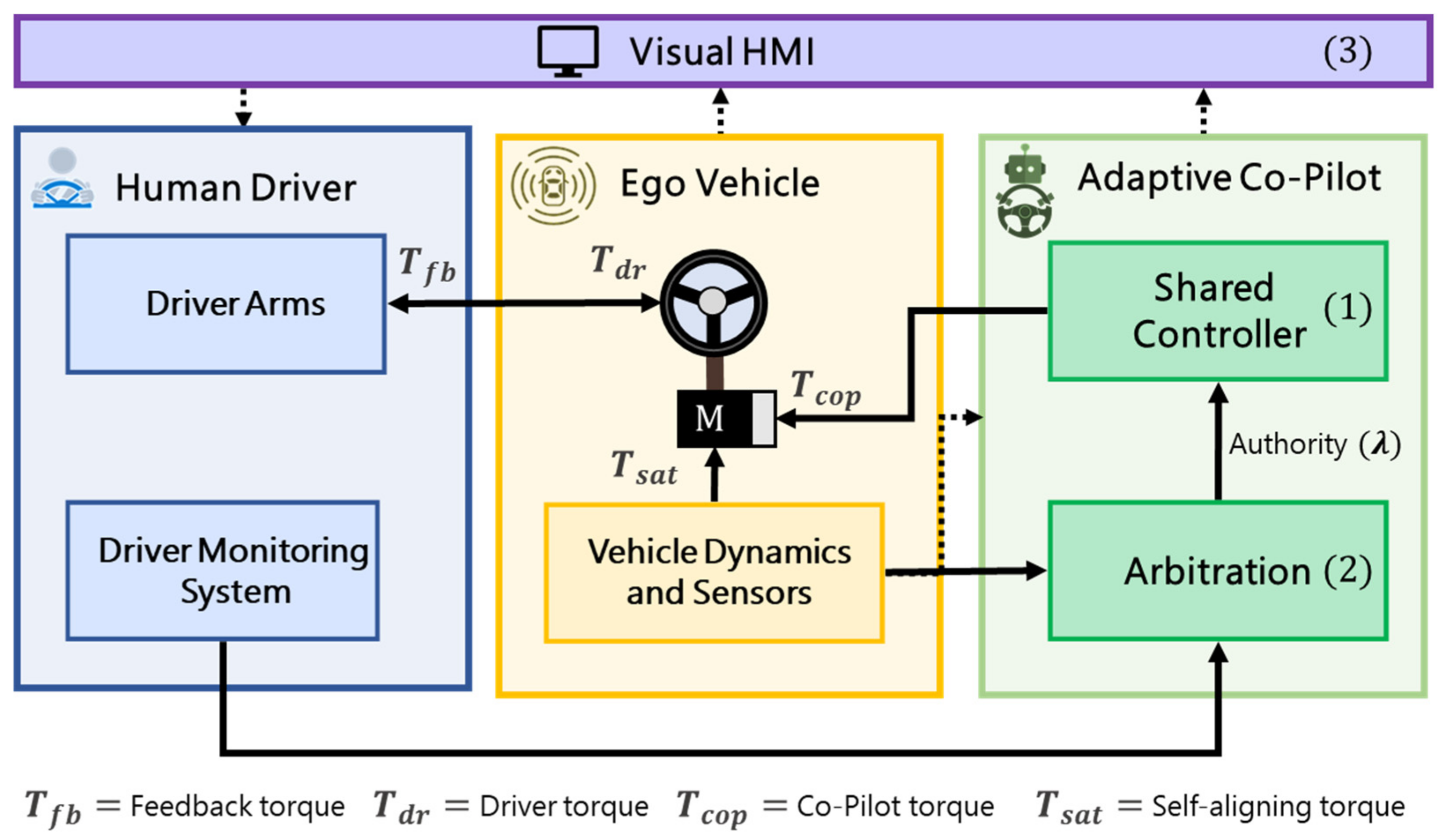
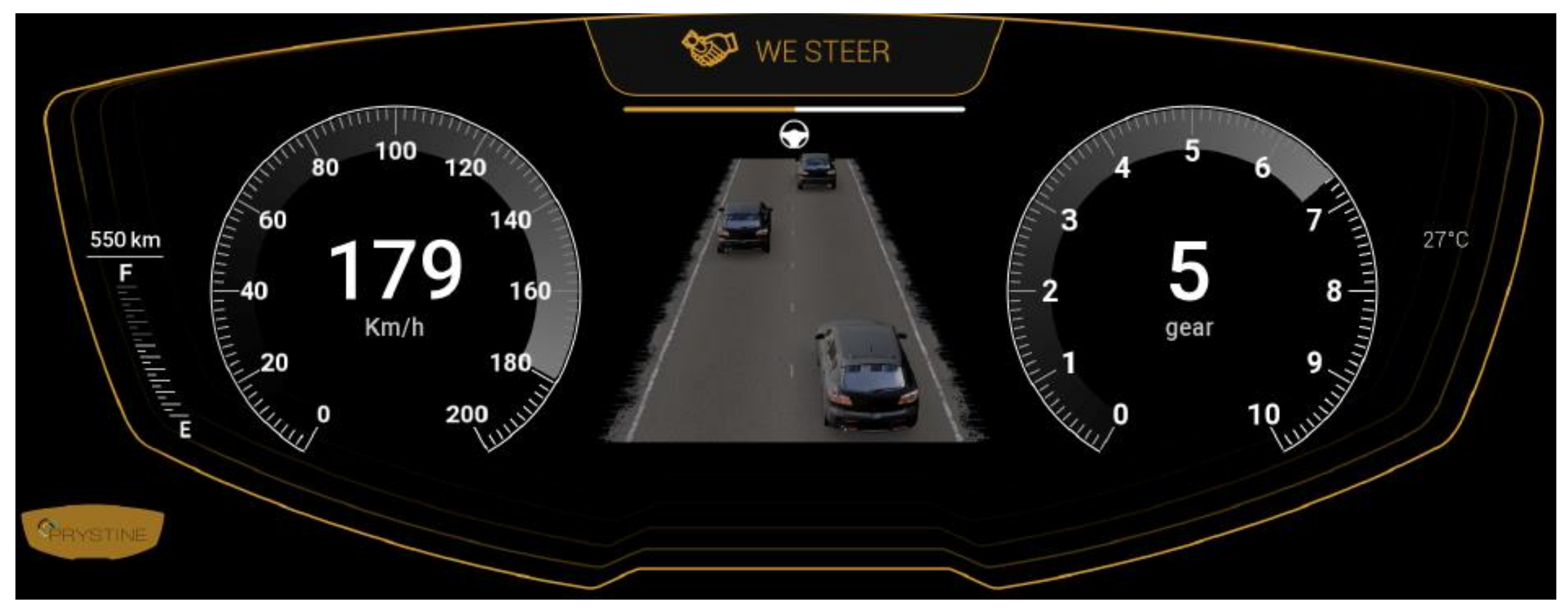
- Development (Section 2): Three components of the adaptive co-pilot are presented in this work: (1) a novel lateral shared controller, able to assist the driver with different levels of haptic authority, (2) an arbitration module that calculates the authority to be assigned to the controller, designed under two principles (minimal intervention and safety-over-comfort), and (3) an innovative visual HMI for shared control, as the enabler of trust in decisions and actions performed by the co-pilot.
- Testing (Section 3.1): The implementation of the adaptive co-pilot is then tested in a scenario where the driver is asked to repeatedly perform a secondary task, which results in two general driver states (attentive or distracted). Under this scenario, four driving modes are compared (manual as a baseline, and LK and LC as two available commercial ADAS, and the proposed adaptive co-pilot). The last three offer steering support to the driver to keep within the lane in both attentive and distracted states. Tests were carried out in a driver-in-the-loop simulator with five drivers.
- Evaluation (Section 3.2 and Section 3.3): A quantitative analysis of the tests was performed, considering KPIs related to tracking performance, safety indicators, and driving efforts. To complement the study, a subjective evaluation was also performed through questionnaires applied to the participants, with KPIs related to safety, comfort, and overall perception of the system. Results show that when the driver is continuously kept in the loop under the support of the adaptive co-pilot, it provides benefits in regards to the driving task that would help to avoid “automation irony” (as the driver has a sense of being responsible for driving even under automation support). At the same time, drivers benefit from the automation capabilities for intervening during the distraction events and improving driving safety, while reducing driver-required efforts.
2. Materials and Methods
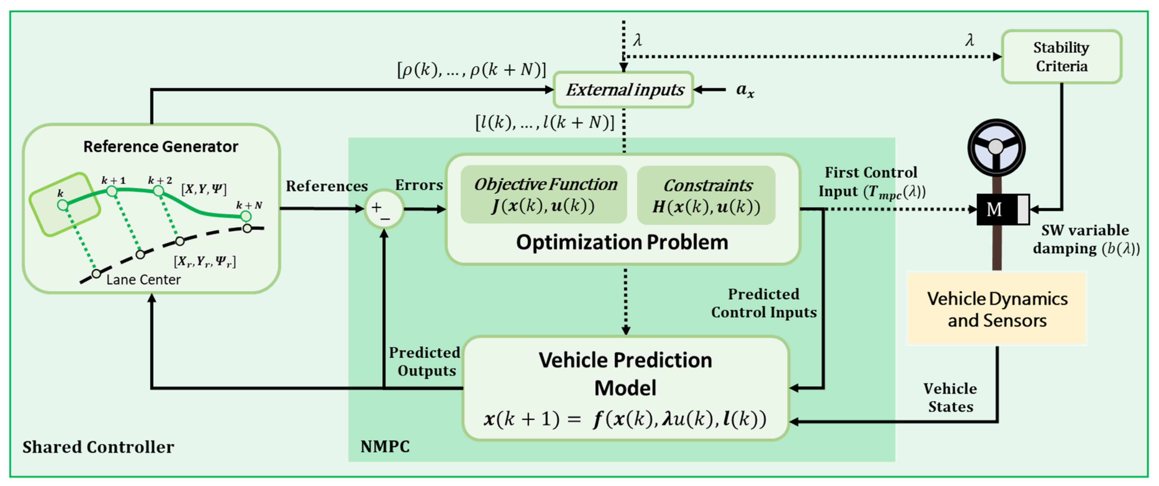
2.1. Adaptive Co-Pilot—Shared Controller
- The control signal (controller output) is the steering wheel torque, whereas conventional autopilots use the steering wheel angle [25] or even the angular velocity [26]. However, drivers control the steering wheel by applying torque with the arms-hands mechanism, and it has been shown that steering angle control decreases the ease of driver intervention (as it has to deal with the low lever position controller) [27]. Therefore, to couple the control signals of both agents, a torque-based lateral controller is designed, similar to previous works in lateral shared control that have followed the same approach [28].
- The authority of the controller is adaptative to the ever-changing environment and context, whereas conventional autopilots assign a single authority value to the controller, being either activated (authority = 1, or maximum torque applied) or deactivated (authority = 0). In autopilots, the context may change the behavioral planner, but the core controller remains with the same authority, whereas for the driver–automation “team”, the automation support can adapt its intensity according to the conditions of each scenario (changes in driver fit-to-drive conditions, unsafe driver actions, automation failures, and others). This means automation can assist the driver with different levels of intensity (authority), covering the continuous spectrum from “no assistance” to “maximum allowed assistance”. In the literature, this intensity is known as the level of haptic authority [22,29].
- The control method is able to perform optimization of multiple objectives, as the complex interaction between driver and automation creates a series of goals such as tracking performance, driver comfort, driving efforts, and safety, which cannot always be achieved at the same time. Therefore, a controller capable of balancing those objectives efficiently is ideal for the adaptive co-pilot. Whereas classical controllers such as PIDs have been widely used for autopilots, shared control applications are more benefited by optimal control algorithms that allow minimizing functions with multiple objectives, with the additional benefit of managing constraints of vehicle dynamic states and control signals [8].
2.1.1. The Vehicle Model
2.1.2. The Optimization Problem
2.1.3. The Adaptive Authority
2.1.4. The Stability Criteria
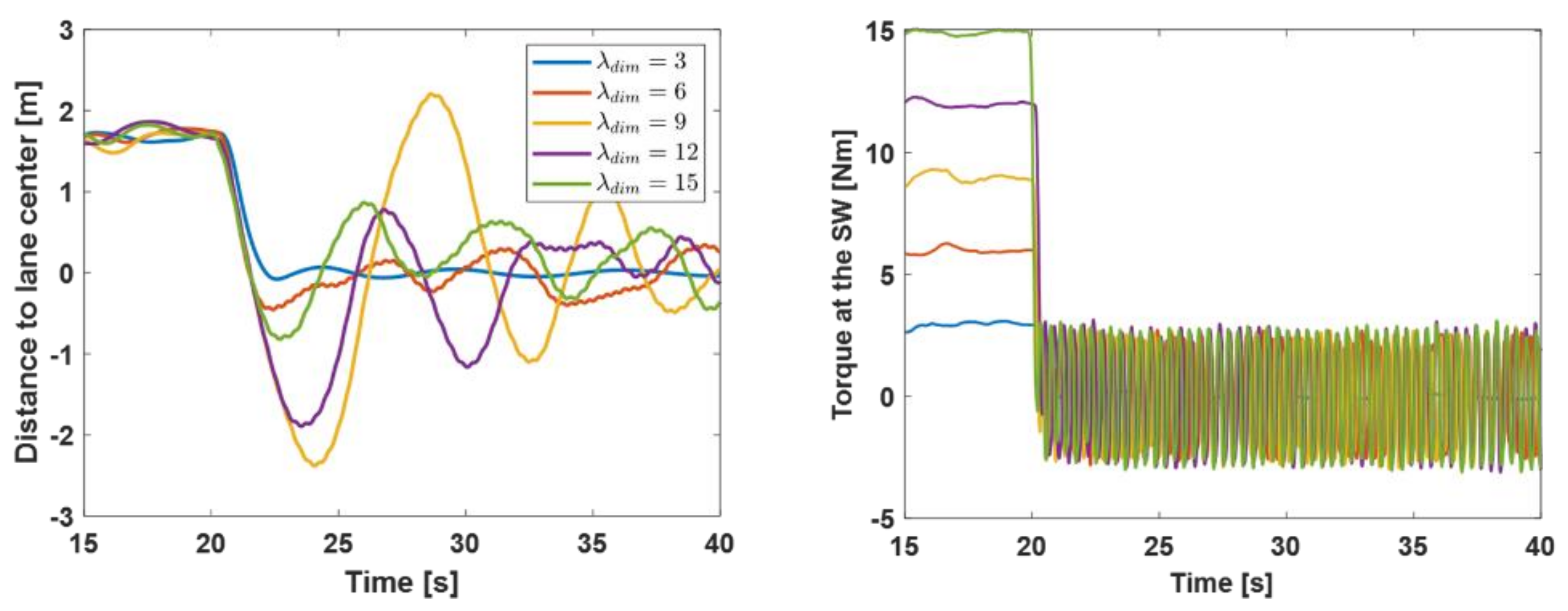
2.1.5. The Authority Dimension
2.2. Adaptive Co-Pilot—Arbitration
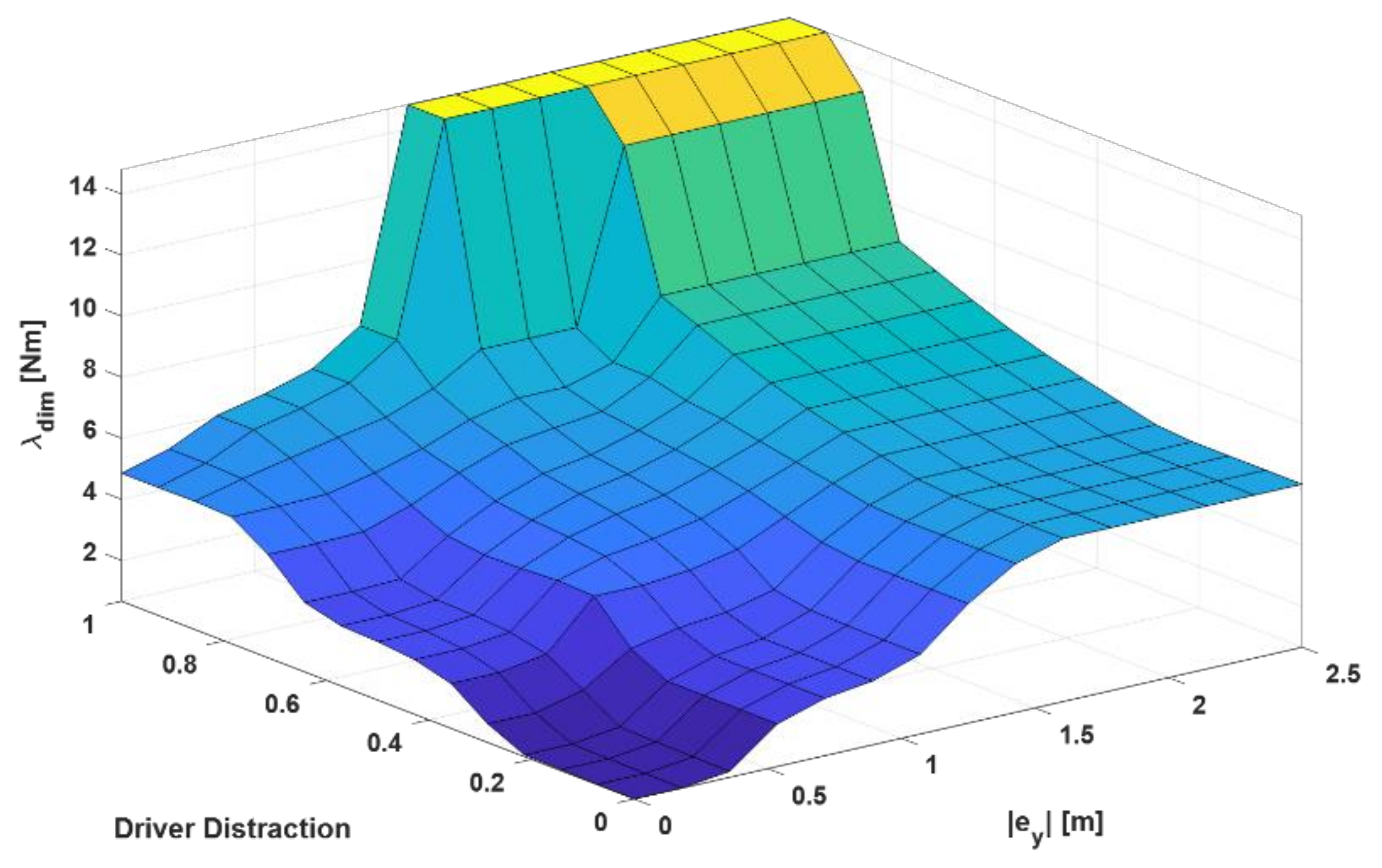
- The minimal intervention principle follows the idea that drivers only need assistance under specific circumstances; on the contrary, automation could create unnecessary conflicts that will produce a feeling for the driver of being controlled all the time, and decrease the driver acceptance rate. Additionally, not intervening when drivers are in suitable conditions to drive aims to increase the sense of responsibility for the driving task, in order to avoid over-trust in automation. Moreover, the inclusion of the lateral error in the logic is part of this principle, as assistance should not be given to the driver only considering the distraction level (as the driver could maintain a safe performance even under some levels of distraction). Therefore, a combination of performance (lateral error) and driver state (distraction level) is needed.
- The safety over comfort principle is based on the fact that safety has a higher priority over the parameters that add comfort to the driving task. In this sense, if the driver is not in a condition to drive, and is also performing an unsafe action, then the system has to intervene even if it overrides the driver or the maneuver creates discomfort (e.g., high lateral acceleration or strong torque at the steering wheel).
2.3. Visual HMI
3. Results
3.1. Driving Performance Test
3.1.1. User Story
3.1.2. Experimental Conditions
3.1.3. Key Performance Indicators
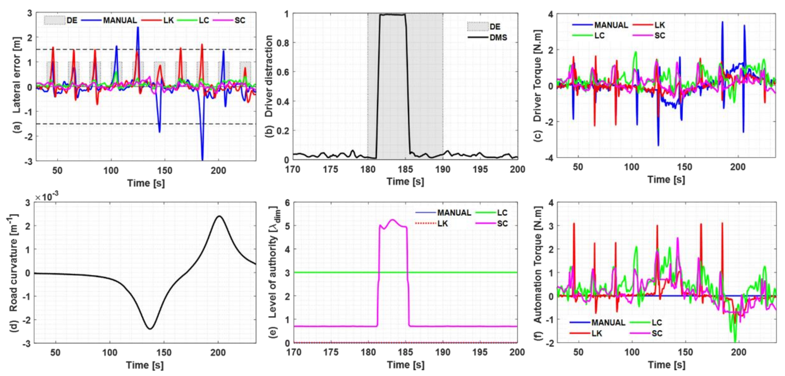
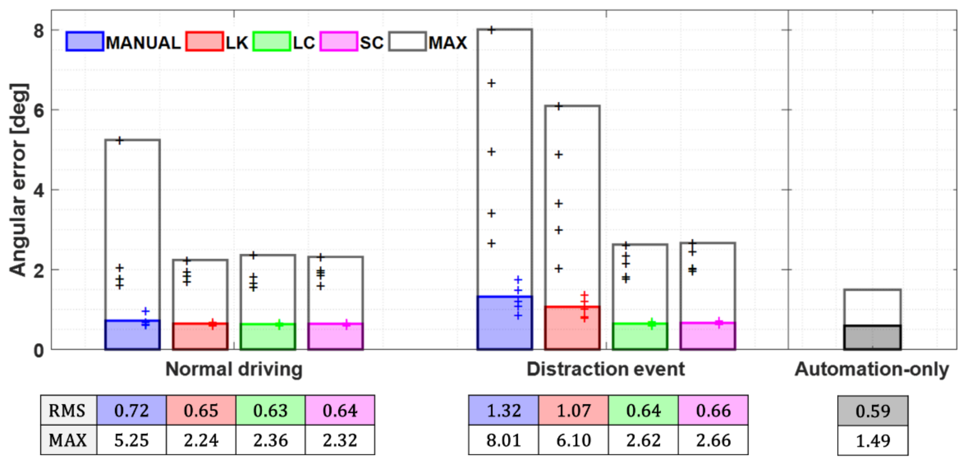
- Tracking errors: the ability to follow the expected trajectory is evaluated by the RMS and maximum (MAX) lateral and angular tracking errors.
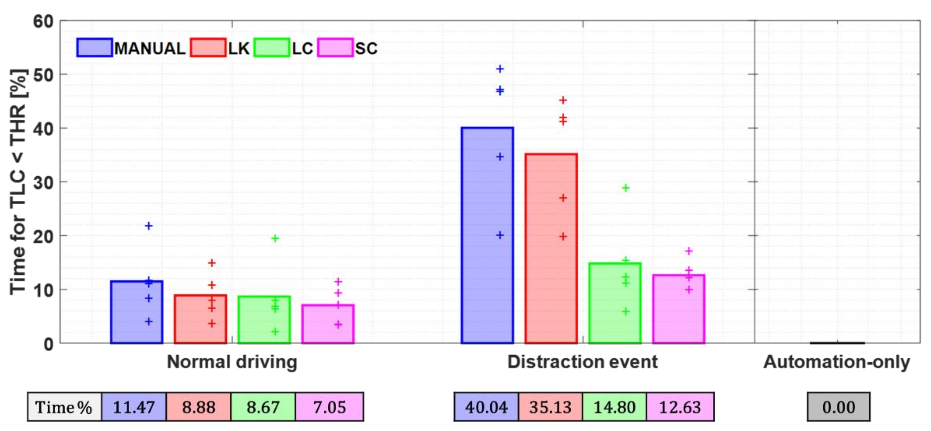
- Safety indicators: the RMS and minimum (MIN) TLC indicate how close (in time) the vehicle is from departing the lane limits. It is estimated at any given time assuming the steering angular speed would remain unchanged. Additionally, the percentage of the time driven with the TLC below a threshold of 3.8 s (the minimum TLC when the automated system drives alone by the testing route, with the configuration of the nominal controller) provides a measure of the risk exposure.
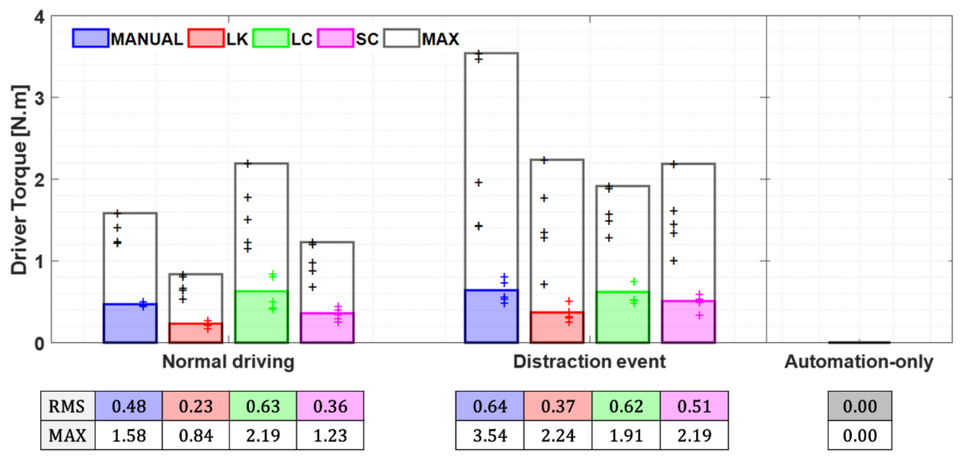
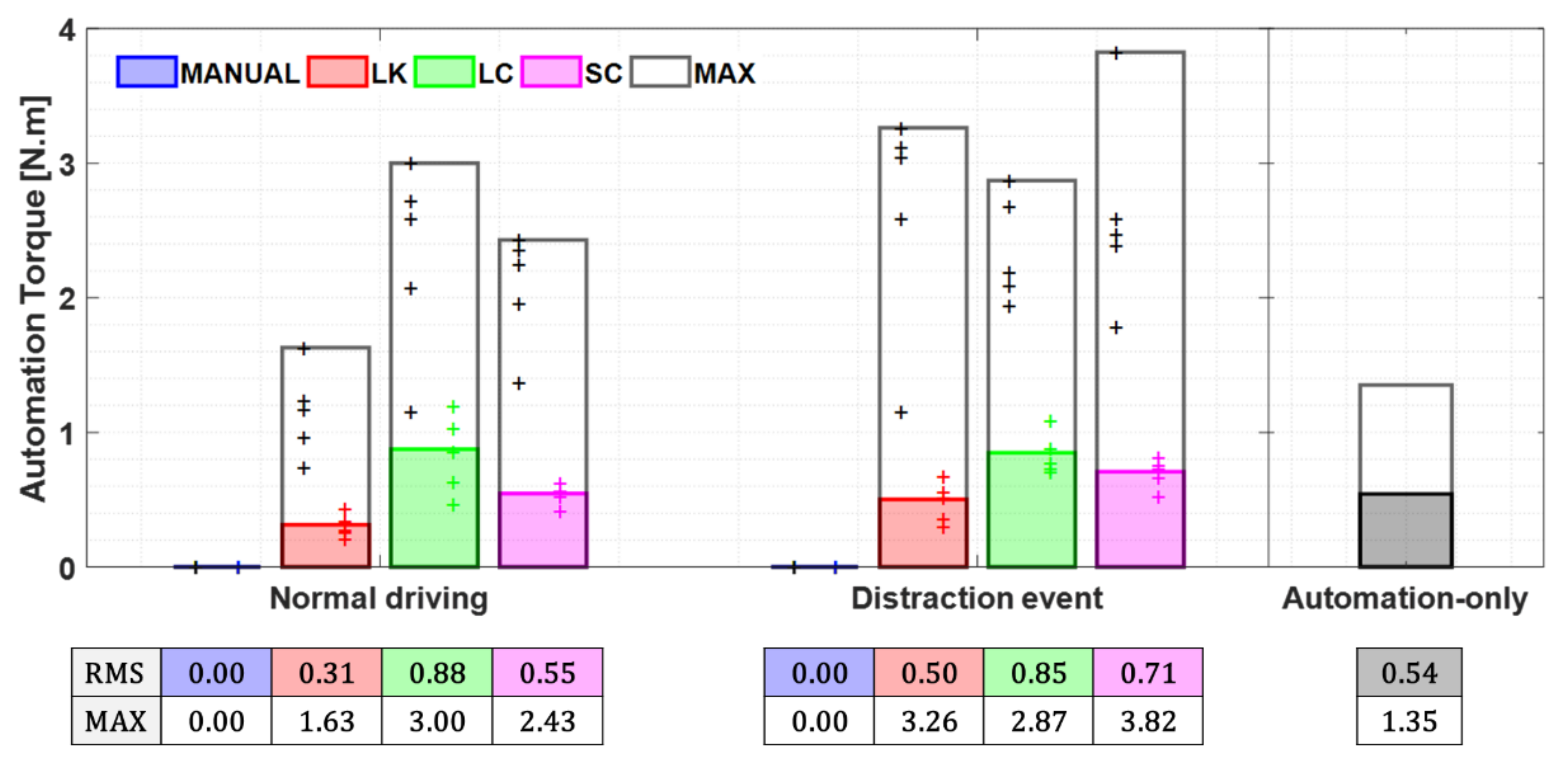
- Driving efforts: the RMS and maximum torque exerted by the driver provide a measure of the effort applied, which relates to conflict and comfort. The RMS and maximum automation torque provide a measure of the work performed by the system and are related to its efficiency.
- Safety-related indicators: evaluate the driver’s sense of being protected, being allowed to perform the secondary task, or being required to continuously monitor the environment.
- Comfort-related indicators: evaluate the driver’s feeling of the system being harmonious or too intrusive in its interaction.
- Overall driver perception: evaluates the driver’s assessment of the system, using its own criteria to ponder safety and comfort behavior.
3.2. Quantitative Evaluation (Experimental Results)
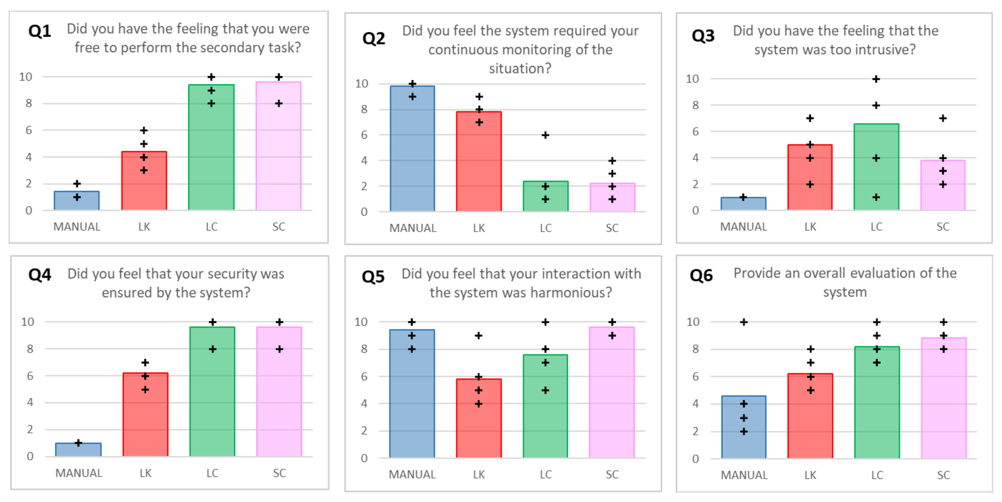
3.3. Qualitative Evaluation (Questionnaires)
- Did you have the feeling that you were free to perform the secondary task?
- Did you feel the system required your continuous monitoring of the situation?
- Did you have the feeling that the system was too intrusive?
- Did you feel that your security was ensured by the system?
- Did you feel that your interaction with the system was harmonious?
- Provide an overall evaluation of the system.
4. Discussion
- Extend the experiments presented in this work, with a larger number of participants, a more realistic scenario with higher curvature sections, other secondary tasks, and additional metrics (e.g., secondary task fulfillment evaluation and take-over performance when automation support is unexpectedly deactivated). In particular, the take-over behavior will be a key aspect in the acceptance of the SC mode in the future, as it is expected to result in better performance in comparison to when the driver is kept out of the loop.
- Extend the scenarios beyond the distracted driver, using the driving simulator again. With reference to the work of Okada and colleagues [54], we will include curves and other road layouts. Moreover, two additional use-cases will be evaluated: (1) support in collision avoidance of sudden obstacles when driving in automated mode, and (2) support in an overtaking maneuver, evaluating transitions from automated to manual, initiated by the driver when the AD cannot perform this maneuver due to—for example—limitations in perception. In such a situation, the system informs the driver and asks for support. Two possibilities can be investigated: cooperation in perception (where the influence of visual HMI presented in this work will be evaluated) and real-time cooperation in action.
- Integration of the HMI: while presented in this work as an initial prototype, the next step is to integrate the visual HMI with real data coming from the simulator, to be used in the experimental test to evaluate its effectiveness as an enabler of trust in decisions and actions performed by the co-pilot.
- Implementation of the co-pilot enabler in a real demonstrator vehicle, using an automated Renault Twizy.
5. Conclusions
Author Contributions
Funding
Institutional Review Board Statement
Informed Consent Statement
Data Availability Statement
Conflicts of Interest
References
- National Highway Traffic Safety Administration; U.S Department of Transportation. TRAFFIC SAFETY FACTS Crash • Stats Critical Reasons for Crashes Investigated in the National Motor Vehicle Crash Causation Survey. 2015. Available online: https://crashstats.nhtsa.dot.gov/api/public/viewpublication/812115 (accessed on 24 May 2021).
- Flemisch, F.; Schieben, A.; Schoemig, N.; Strauss, M.; Lueke, S.; Heyden, A. Design of human computer interfaces for highly automated vehicles in the EU-project HAVEit. In International Conference on Universal Access in Human-Computer Interaction; Springer: Berlin/Heidelberg, Germany, 2011; Volume 6767, pp. 270–279. [Google Scholar] [CrossRef]
- J3016B: Taxonomy and Definitions for Terms Related to Driving Automation Systems for On-Road Motor Vehicles—SAE International. Available online: https://www.sae.org/standards/content/j3016_201806/ (accessed on 27 May 2021).
- Da Lio, M.; Biral, F.; Bertolazzi, E.; Galvani, M.; Bosetti, P.; Windridge, D.; Saroldi, A.; Tango, F. Artificial Co-Drivers as a Universal Enabling Technology for Future Intelligent Vehicles and Transportation Systems. IEEE Trans. Intell. Transp. Syst. 2014, 16, 244–263. [Google Scholar] [CrossRef]
- Flemish, F.O.; Goodrich, K.H.; Adams, A.A.; Conway, S.R.; Palmer, M.T.; Schutte, P.C. The H-Metaphor as a Guideline for Vehicle Automation and Interaction; University of Munich: Munich, Germany, 2003. Available online: http://www.sti.nasa.gov (accessed on 24 May 2021).
- Bainbridge, L. Ironies of automation. Automatica 1983, 19, 775–779. [Google Scholar] [CrossRef]
- Jerry, W. By what Hubris? The readiness of the human operator to take over when the automation fails or hands over control. In Proceedings of the DDI2018 6th International Conference on Driver Distraction and Inattention, Gothenburg, Sweden, 15–17 October 2018; pp. 182–184. [Google Scholar]
- Marcano, M.; Iaz, S.D.; Perez, J.; Irigoyen, E. A Review of Shared Control for Automated Vehicles: Theory and Applications. IEEE Trans. Hum. Mach. Syst. 2020, 50, 475–491. [Google Scholar] [CrossRef]
- Bhardwaj, A.; Ghasemi, A.H.; Zheng, Y.; Febbo, H.; Jayakumar, P.; Ersal, T.; Stein, J.L.; Gillespie, R.B. Who’s the boss? Arbitrating control authority between a human driver and automation system. Transp. Res. Part F Traffic Psychol. Behav. 2020, 68, 144–160. [Google Scholar] [CrossRef]
- Kaber, D.B.; Endsley, M.R. Out-of-the-loop performance problems and the use of intermediate levels of automation for improved control system functioning and safety. Process. Saf. Prog. 1997, 16, 126–131. [Google Scholar] [CrossRef]
- Stanton, N.A.; Marsden, P. From fly-by-wire to drive-by-wire: Safety implications of automation in vehicles. Saf. Sci. 1996, 24, 35–49. [Google Scholar] [CrossRef] [Green Version]
- Rudin-Brown, C.M.; Parker, H.A. Behavioural adaptation to adaptive cruise control (ACC): Implications for preventive strategies. Transp. Res. Part F Traffic Psychol. Behav. 2004, 7, 59–76. [Google Scholar] [CrossRef]
- Saffarian, M.; de Winter, J.C.F.; Happee, R. Automated Driving: Human-Factors Issues and Design Solutions. Proc. Hum. Factors Ergon. Soc. Annu. Meet. 2012, 56, 2296–2300. [Google Scholar] [CrossRef]
- Vorndran, I. Unfallentwicklung auf Deutschen Straßen; Statistisches Bundesamt: Wiesbaden, Germany, 2010; Available online: https://www.destatis.de/EN/Methods/WISTAScientificJournal/_node.html;jsessionid=734A3E16437E203E3ACFD9CE125115B3.live742 (accessed on 24 May 2021).
- Martens, M.H.; Beukel, A.P.V.D. The road to automated driving: Dual mode and human factors considerations. In Proceedings of the 16th International IEEE Conference on Intelligent Transportation Systems (ITSC 2013), The Hague, The Netherlands, 6–9 October 2013; pp. 2262–2267. [Google Scholar] [CrossRef]
- Eriksson, A.; Stanton, N.A. The Chatty Co-Driver: A Linguistics Approach to Human-Automation-Interaction. In Contemporary Ergonomics and Human Factors; Charles, R., Wilkinson, J., Eds.; CIEHF: London, UK, 2016. [Google Scholar]
- Grice, H. Logic and Conversation. In Speech Acts; Cole, P., Morgan, J.L., Eds.; Brill: New York, NY, USA, 1975; pp. 41–58. Available online: https://brill.com/view/book/edcoll/9789004368811/BP000003.xml (accessed on 24 May 2021).
- Flemisch, F.; Abbink, D.; Itoh, M.; Pacaux-Lemoine, M.-P.; Weßel, G. Shared control is the sharp end of cooperation: Towards a common framework of joint action, shared control and human machine cooperation. IFAC PapersOnLine 2016, 49, 72–77. [Google Scholar] [CrossRef]
- Mosier, K.L. Automation and cognition: Maintaining coherence in the electronic cockpit. Adv. Hum. Perform. Cogn. Eng. Res. 2002, 2, 93–121. [Google Scholar] [CrossRef]
- Marcano, M.; Díaz, S.; Pérez, J.; Castellano, A.; Landini, E.; Tango, F.; Burgio, P. Human-Automation Interaction Through Shared and Traded Control Applications. Adv. Intell. Syst. Comput. 2020, 1131, 653–659. [Google Scholar] [CrossRef]
- Automate Project—Automation Accepted and Trusted Teammate to Enhance Traffic Safety and Efficiency. Available online: https://www.automate-project.eu/ (accessed on 24 May 2021).
- Benloucif, M.; Sentouh, C.; Floris, J.; Simon, P.; Popieul, J.-C. Online adaptation of the Level of Haptic Authority in a lane keeping system considering the driver’s state. Transp. Res. Part F Traffic Psychol. Behav. 2019, 61, 107–119. [Google Scholar] [CrossRef]
- Billings, C.E. Aviation Automation: The Search for A Human-Centered Approach, 1st ed.; CRC Press: Boca Raton, FL, USA, 1996; Available online: https://www.routledge.com/Aviation-Automation-The-Search-for-A-Human-centered-Approach/Billings/p/book/9780805821277 (accessed on 24 May 2021).
- Gonzalez, D.; Perez, J.; Milanes, V.; Nashashibi, F. A Review of Motion Planning Techniques for Automated Vehicles. IEEE Trans. Intell. Transp. Syst. 2015, 17, 1135–1145. [Google Scholar] [CrossRef]
- Matute-Peaspan, J.A.; Zubizarreta-Pico, A.; Diaz-Briceno, S.E. A Vehicle Simulation Model and Automated Driving Features Validation for Low-Speed High Automation Applications. IEEE Trans. Intell. Transp. Syst. 2020, 1–10. [Google Scholar] [CrossRef]
- Perez, J.; Milanes, V.; Onieva, E. Cascade Architecture for Lateral Control in Autonomous Vehicles. IEEE Trans. Intell. Transp. Syst. 2011, 12, 73–82. [Google Scholar] [CrossRef]
- Nagai, M.; Mouri, H.; Raksincharoensak, P. Vehicle Lane-Tracking Control with Steering Torque Input. Veh. Syst. Dyn. 2002, 37, 267–278. [Google Scholar] [CrossRef]
- Sentouh, C.; Nguyen, A.-T.; Benloucif, M.A.; Popieul, J.-C. Driver-Automation Cooperation Oriented Approach for Shared Control of Lane Keeping Assist Systems. IEEE Trans. Control Syst. Technol. 2018, 27, 1962–1978. [Google Scholar] [CrossRef]
- Van Paassen, M.M.; Boink, R.P.; Abbink, D.; Mulder, M.; Mulder, M. Four design choices for haptic shared control. Adv. Aviat. Psychol. 2017, 2, 237–254. [Google Scholar] [CrossRef]
- Guo, C.; Sentouh, C.; Popieul, J.-C.; Haué, J.-B. Predictive shared steering control for driver override in automated driving: A simulator study. Transp. Res. Part F Traffic Psychol. Behav. 2019, 61, 326–336. [Google Scholar] [CrossRef]
- Ercan, Z.; Carvalho, A.; Tseng, H.E.; Gökaşan, M.; Borrelli, F. A predictive control framework for torque-based steering assistance to improve safety in highway driving. Veh. Syst. Dyn. 2017, 56, 810–831. [Google Scholar] [CrossRef]
- Bao, C.; Feng, J.; Wu, J.; Liu, S.; Xu, G.; Xu, H. Model predictive control of steering torque in shared driving of autonomous vehicles. Sci. Prog. 2020, 103. [Google Scholar] [CrossRef] [PubMed]
- Lazcano, A.M.R.; Niu, T.; Akutain, X.C.; Cole, D.; Shyrokau, B. MPC-based Haptic Shared Steering System: A Driver Modelling Approach for Symbiotic Driving. IEEE/ASME Trans. Mechatron. 2021, 1. [Google Scholar] [CrossRef]
- Camacho, E.F.; Bordons, C. Introduction to model predictive control. In Advanced Textbooks in Control and Signal Processing; Springer International Publishing: Berlin/Heidelberg, Germany, 2007; pp. 1–11. [Google Scholar] [CrossRef]
- Marcano, M.; Díaz, S.; Matute, J.A.; Irigoyen, E.; Pérez, J. A cascade steering shared controller with dual-level dynamic authority. IFAC-PapersOnLine 2020, 53, 15353–15359. [Google Scholar] [CrossRef]
- Matute-Peaspan, J.A.; Marcano, M.; Diaz, S.; Zubizarreta, A.; Perez, J. Lateral-Acceleration-Based Vehicle-Models-Blending for Automated Driving Controllers. Electronics 2020, 9, 1674. [Google Scholar] [CrossRef]
- Erlien, S.M.; Fujita, S.; Gerdes, J.C. Shared Steering Control Using Safe Envelopes for Obstacle Avoidance and Vehicle Stability. IEEE Trans. Intell. Transp. Syst. 2015, 17, 441–451. [Google Scholar] [CrossRef]
- Mayne, D.; Rawlings, J.; Rao, C.; Scokaert, P. Constrained model predictive control: Stability and optimality. Automatica 2000, 36, 789–814. [Google Scholar] [CrossRef]
- Li, M.; Cao, H.; Li, G.; Zhao, S.; Song, X.; Chen, Y.; Cao, D. A Two-Layer Potential-Field-Driven Model Predictive Shared Control Towards Driver-Automation Cooperation. IEEE Trans. Intell. Transp. Syst. 2020, 1–17. [Google Scholar] [CrossRef]
- De Winter, J.; Stanton, N.; Eisma, Y.B. Is the take-over paradigm a mere convenience? Transp. Res. Interdiscip. Perspect. 2021, 10, 100370. [Google Scholar] [CrossRef]
- Marcano, M.; Castellano, A.; Díaz, S.; Pérez, J.; Tango, F.; Landini, E.; Burgio, P. Shared and traded control for human-automation interaction: A haptic steering controller and a visual interface. Hum. Intell. Syst. Integr. 2021, 3, 25–35. [Google Scholar] [CrossRef]
- Masola, A.; Gabbi, C.; Castellano, A.; Capodieci, N.; Burgio, P. Graphic Interfaces in ADAS: From requirements to implementation. In Proceedings of the GoodTechs ’20: 6th EAI International Conference on Smart Objects and Technologies for Social Good, Antwerp, Belgium, 14–16 September 2020. [Google Scholar] [CrossRef]
- Vaca-Recalde, M.E.; Pérez, J.; Echanobe, J. Driver Monitoring System Based on CNN Models: An Approach for Attention Level Detection. In Proceedings of the 21st International Conference, Guimaraes, Portugal, 4–6 November 2020; pp. 575–583. [Google Scholar] [CrossRef]
- Pena, A.; Iglesias, I.; Valera, J.J.; Martin, A. Development and validation of Dynacar RT software, a new integrated solution for design of electric and hybrid vehicles. In Proceedings of the EVS26 International Battery, Hybrid and Fuel Cell Electric Vehicle Symposium, Los Angeles, CA, USA, 6–9 May 2012; Volume 3, pp. 2026–2032. Available online: https://www.researchgate.net/publication/280482628 (accessed on 29 May 2021).
- Houska, B.; Ferreau, H.J.; Diehl, M. ACADO toolkit-An open-source framework for automatic control and dynamic optimization. Optim. Control. Appl. Methods 2010, 32, 298–312. [Google Scholar] [CrossRef]
- Becker, C.; Yount, L.; Rosen-Levy, S.; Brewer, J.; NHTSA. Functional Safety Assessment of an Automated Lane Centering System. 2018. Available online: https://rosap.ntl.bts.gov/view/dot/37211 (accessed on 10 May 2021).
- Druml, N.; Debaillie, B.; Anghel, A.; Ristea, N.C.; Fuchs, J.; Dubey, A.; Reißland, T.; Hartstem, M.; Rack, V.; Ryabokon, A.; et al. Programmable Systems for Intelligence in Automobiles (PRYSTINE): Technical Progress after Year 2. In Proceedings of the 2020 23rd Euromicro Conference on Digital System Design (DSD), Kranj, Slovenia, 26–28 August 2020; pp. 360–369. [Google Scholar] [CrossRef]
- Flemisch, F.; Heesen, M.; Hesse, T.; Kelsch, J.; Schieben, A.; Beller, J. Towards a dynamic balance between humans and automation: Authority, ability, responsibility and control in shared and cooperative control situations. Cogn. Technol. Work. 2011, 14, 3–18. [Google Scholar] [CrossRef]
- Nishimura, R.; Wada, T.; Sugiyama, S. Haptic Shared Control in Steering Operation Based on Cooperative Status Between a Driver and a Driver Assistance System. J. Hum. Robot. Interact. 2015, 4, 19. [Google Scholar] [CrossRef]
- Abbink, D.A.; Mulder, M. Exploring the Dimensions of Haptic Feedback Support in Manual Control. J. Comput. Inf. Sci. Eng. 2009, 9, 011006. [Google Scholar] [CrossRef]
- Inagaki, T. Hanbook of Cognitive Task Design, 8 Adaptive Automation: Sharing and Trading of Control. In Handbook of Cognitive Task Design; Lawrence Erlbaum Associates: Mahwah, NJ, USA, 2003; pp. 147–169. Available online: https://books.google.es/books?hl=es&lr=&id=dElPH0ruR-sC&oi=fnd&pg=PA147&dq=Adaptive+automation:+Sharing+and+trading+of+control&ots=EIhPp04ODA&sig=N5BmD9McjzgF353NV1i-AkXork4 (accessed on 31 May 2021).
- Devitt, S.K. Trustworthiness of autonomous systems. In Studies in Systems, Decision and Control; Springer International Publishing: Berlin/Heidelberg, Germany, 2018; Volume 117, pp. 161–184. [Google Scholar] [CrossRef] [Green Version]
- Schaefer, K.E.; Chen, J.Y.C.; Szalma, J.L.; Hancock, P.A. A Meta-Analysis of Factors Influencing the Development of Trust in Automation. Hum. Factors J. Hum. Factors Ergon. Soc. 2016, 58, 377–400. [Google Scholar] [CrossRef] [PubMed] [Green Version]
- Okada, K.; Sonoda, K.; Wada, T. Control transfer method from automated driving to manual driving during curve travel. In Proceedings of the 2019 IEEE International Conference on Systems, Man and Cybernetics (SMC), Bari, Italy, 6–9 October 2019; pp. 3130–3135. [Google Scholar] [CrossRef]


| Abbreviation | Meaning | Abbreviation | Meaning |
|---|---|---|---|
| ADAS | Advanced Driver Assistance System | LoA | Level of Automation |
| ADS | Automated Driving System | MF | Membership Function |
| AI | Artificial Intelligence | MPC | Model Predictive Control |
| AV | Automated Vehicle | NMPC | Non-linear MPC |
| FIS | Fuzzy Inference System | ODD | Operational Design Domain |
| HMI | Human–Machine Interface | RMS | Root Mean Square |
| ITS | Intelligent Transportation Systems | SAE | Society of Automotive Engineers |
| KPI | Key Performance Indicator | SC | Shared Control |
| LC | Lane-Centering | TLC | Time to Lane Crossing |
| LK | Lane-Keeping | TOR | Take-Over Request |
| State Vector | Prediction Model Function | Optimization Function | Constraints | Equation N° |
|---|---|---|---|---|
| Vehicle Model | ||||
| X-coordinate | (Tracking) | (1) | ||
| Y-coordinate | (Tracking) | (2) | ||
| Yaw angle | (Tracking) | (3) | ||
| Long. speed | 0 | (4) | ||
| Lateral speed | (5) | |||
| Yaw rate | (Comfort) | (6) | ||
| Algebraic Expressions for Tire Model | ||||
| Lat. Force front | (7) | |||
| Lat. Force rear | (8) | |||
| Tracking-errors Model | ||||
| Lateral error | (9) | |||
| Angular error | (10) | |||
| Steering Wheel Model | ||||
| Sw. angle | ; | (11) | ||
| Angular speed | (Comfort) | (12) | ||
|
Control Input | Input Model Function | Optimization Function | Constraint | Equation N° |
|---|---|---|---|---|
| Control torque (u) | (Effort) | (13) | ||
| Control torque rate of change () | (Effort) | (14) |
| Parameter | Value | Parameter | Value | Parameter | Value |
|---|---|---|---|---|---|
| Vehicle mass | 1650 kg | Motor inertia | 0.1 kg·m2 | Cornering stiffness front-rear () | 940 × 102 N 118 × 103 N |
| Vehicle inertia | 3234 kg·m2 | Motor damping | 0.65 N·s/rad | MPC horizon (N) | 30 |
| Distance to axis front-rear | 1.40 m 1.65 m | Steering ratio | 8.77 | MPC sample-time () | 0.05 s |
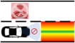
| Variable | N° of MFs | [Labels] → [Values] | MFs |
|---|---|---|---|
| Inputs | |||
| Lateral error | 4 | NONE = [−1.5 −0.57 −0.04 0.33] LOW = [−3.5 −0.01 0.32 1.04] MED = [0.34 1.15 1.52] HIGH = [1.04 1.54 2.54 3.04] |  |
| Driver distraction | 3 | LOW = [−0.53 −0.21 −0.01 0.87] MED = [0.26 0.68 0.91] HIGH = [0.63 0.94 1.29 1.54] | 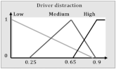 |
| Outputs | |||
| Authority | 4 | MAN = [−1 0 0.5 2] LOW = [0.5 2 6] MED = [2.02 6.02 10] HIGH = [14.3 14.8 24.3 24.8] | 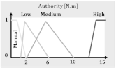 |
| IF-THEN Rules | |||
|---|---|---|---|
| Input () | Input () | Output () | Design Strategy |
| LOW | LOW | MANUAL | Min. Intervention |
| MEDIUM | LOW | Safety + Comfort | |
| HIGH | MEDIUM | Safety + Comfort | |
| MEDIUM | LOW | LOW | Min. Intervention |
| MEDIUM | MEDIUM | Safety + Comfort | |
| HIGH | HIGH | Safety over Comfort | |
| HIGH | NONE | LOW | Min. Intervention |
| LOW | MEDIUM | Safety + Comfort | |
| MEDIUM | HIGH | Safety over Comfort | |
| HIGH | HIGH | Safety over Comfort | |
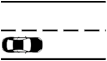
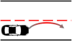
| Manual Driving (MANUAL) | Lane Keeping (LK) | Lane Centering (LC) | Shared Control (SC) | |
|---|---|---|---|---|
| No torque is applied by the automation. The driver only feels the self-aligning torque. | When the vehicle approaches the border line, the vehicle intervenes, applying a momentary torque. | A continuous torque is applied to keep the vehicle on a reference trajectory within the lane. | If the driver is attentive, they receive minimal correction torque, which only increases when getting close to the borders. If the driver is distracted, the authority increases and the free moving range is reduced. | |
| Nm | Nm m Nm | Nm | ||
 |  | 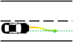 |  |  |
Publisher’s Note: MDPI stays neutral with regard to jurisdictional claims in published maps and institutional affiliations. |
© 2021 by the authors. Licensee MDPI, Basel, Switzerland. This article is an open access article distributed under the terms and conditions of the Creative Commons Attribution (CC BY) license (https://creativecommons.org/licenses/by/4.0/).
Share and Cite
Marcano, M.; Tango, F.; Sarabia, J.; Castellano, A.; Pérez, J.; Irigoyen, E.; Díaz, S. From the Concept of Being “the Boss” to the Idea of Being “a Team”: The Adaptive Co-Pilot as the Enabler for a New Cooperative Framework. Appl. Sci. 2021, 11, 6950. https://doi.org/10.3390/app11156950
Marcano M, Tango F, Sarabia J, Castellano A, Pérez J, Irigoyen E, Díaz S. From the Concept of Being “the Boss” to the Idea of Being “a Team”: The Adaptive Co-Pilot as the Enabler for a New Cooperative Framework. Applied Sciences. 2021; 11(15):6950. https://doi.org/10.3390/app11156950
Chicago/Turabian StyleMarcano, Mauricio, Fabio Tango, Joseba Sarabia, Andrea Castellano, Joshué Pérez, Eloy Irigoyen, and Sergio Díaz. 2021. "From the Concept of Being “the Boss” to the Idea of Being “a Team”: The Adaptive Co-Pilot as the Enabler for a New Cooperative Framework" Applied Sciences 11, no. 15: 6950. https://doi.org/10.3390/app11156950
APA StyleMarcano, M., Tango, F., Sarabia, J., Castellano, A., Pérez, J., Irigoyen, E., & Díaz, S. (2021). From the Concept of Being “the Boss” to the Idea of Being “a Team”: The Adaptive Co-Pilot as the Enabler for a New Cooperative Framework. Applied Sciences, 11(15), 6950. https://doi.org/10.3390/app11156950