Abstract
This paper presents a study on the robotic harvesting of New Mexico type chile pepper, in a laboratory setting, using a five degrees of freedom (DoF) serial manipulator. The end-effector of the manipulator, a scissor-type cutting mechanism, was devised and experimentally tested in a lab setup which cuts the chile stem to detach the fruit. Through a MATLAB™-based program, the location of the chile pepper is estimated in the robot’s reference frame, using Intel RealSense Depth Camera. The accuracy of the 3D location estimation system matches the maximum accuracy claimed by the manufacturer of the hardware, with a maximum error to be in Y-axis, which is 5.7 mm. The forward and inverse kinematics are developed, and the reachable and dexterous workspaces of the robot are studied. An application-based path planning algorithm is developed to minimize the travel for a specified harvesting task. The robotic harvesting system was able to cut the chile pepper from the plant based on 3D location estimated by MATLAB™ program. On the basis of harvesting operation, on 77 chile peppers, the following harvesting indicators were achieved: localization success rate of 37.7%, detachment success rate of 65.5%, harvest success rate of 24.7%, damage rate of 6.9%, and cycle time of 7 s.
1. Introduction
Chile pepper, as the signature crop of the state of New Mexico (NM), plays an important role for many small acreage growers in the predominately Hispanic and Native American population areas in the state [1,2]. The green chile (Capsicum annuum) crop is entirely hand harvested in New Mexico, requiring a large number of farm laborers during a relatively narrow harvest window. High cost and limited labor availability, as reported throughout the U.S. agriculture sector [3,4], are main contributing reasons for reduced chile pepper production in the state of New Mexico over the past two decades. In 2020, the harvested area for the chile pepper was reported to be 3440 ha (8500 acres) [5], which was significantly declined from 13,962 ha (34,500 acres) in 1992 [6]. Harvest labor costs up to 50 percent of the total production cost in USA. The studies have shown that the cost can be reduced up to 10 percent with mechanization or use of robotic harvesting [6]. Despite the extensive attempts to use mechanized chile pepper harvester as early as 1972 [7], these systems have not been adopted by industry for chile pepper harvest. Mechanized harvesting for the chile, specifically, and other crops, in general, has four major tasks [8]. The first task is dividing that the machine separates the fruit from the bushes and leaves as it goes from one plant to another, to avoid damage to the plant and the harvested fruit. Second, being the most important is the detachment of the fruit from the plant. The third step is to grasp and convey the fruit, after being removed from the plant. Fourth is the transportation from the field to the post-processing site and the consumer market. Detachment task in robotic harvesting has extra importance because it is challenging, crop-specific, and has the highest effects on the economic value of the fruit.
In New Mexico, NM-type red chile and paprika, NM-type long green chile, and Cayenne peppers are the three main types of chile peppers that contribute the most to the overall chile industry. Each of these three types of chile requires a different type of mechanization for harvesting, as they differ in size, shape, and uses. Additionally, the product damage for the chile peppers which are sold as fresh market item, like green chile pepper, is not acceptable, which makes the mechanization of harvesting more challenging. Heavy-duty and large harvesting machines can perform in larger field areas where only one harvesting cycle is needed for the crop, as the mechanized harvesters, mostly destroy the plant in their first harvesting process [9]. Moreover, mechanized harvesting is not selective harvesting, so it brings up the bushes and sometimes soil with the fruit. On the other hand, cultivation in a greenhouse and on small farms has been increasing with time, where these harvesters cannot be used because of their larger size. These facts point to the necessity of using other advanced technologies, such as robotic harvesters, for selective and adaptive harvesting, which should be small enough to work in a canopy and harvest from a variety of plants in greenhouses. Such robotic harvesting solutions can also be used in fields.
Robotic systems have been used in farming systems to address growing global challenges in agriculture [3,4,10]. Harvesting has been significantly affected by a consistently shrinking and increasingly more expensive labor force; therefore, there has been substantial research related to the design and development of field robots for harvesting [10,11]. Robotic arms (manipulators) are designed or selected from commercially available platforms with degrees-of-freedom (DoF) varying between two to seven with the majority of them having three [10,12,13,14]. However, none of the past research in harvesting robots has offered systematic analysis and design for the selection of the number of DoF [10]. On the other hand, robotic end-effectors are mostly custom made and specialized for specific crop harvesting. Some of these robotic end-effector grasp and hold the fruit using suction cups [15,16] or a combination of suction cups and robotic fingers [17,18]. The detachment process is carried out using thermal cutting, scissor cutting, or physical twist and pulling for detaching the fruits at the stem [12,14,19].
There have been a lot of research efforts in robotic harvesting for fruits, which are hanging on small plants near the ground [20], including berry and tomato [14,21,22,23]. The fruit removal mechanism adopted by these robots includes: (1) cutting the stem [13,15] and (2) gripping or grasping the fruit and applying a normal force to destem. For example, Gunderman et al. [21] used a soft gripper for berry harvesting which takes into account the fingertip force, fruit size and shape, and nature of the plant. Hohimer et al. [24] recently presented a 5-DoF apple harvesting robotic arm with a soft gripper as end-effector and the detachment mechanism. Some of the other robotic systems use the manipulator’s movement to apply force for the detachment [16,25], rather than just using the torque by the wrist joints. Despite the variation in their core concept, all of the designs considered the requirement of delicate grasping to avoid fruit damage [26,27].
All these harvesting techniques, which grip the fruit and pluck it by applying force have been mainly applied for trees and rigid stem plants. However, for delicate plants, this method can create a lot of damage to the unharvested fruit and plant itself. Harvesting the fruit by cutting the pedicle (the stem holding the fruit with plant) is very useful when the subject plant is very delicate and cannot sustain a lot of force from the robotic manipulator. In this method, there is no extra force applied on the plant, rather the robot simply cuts the pedicle and takes off the fruit. For instance, Liu et al. [15] developed a litchi picking robot with a cutting mechanism. The pneumatic force is transmitted to the cutting blades through a tendon and rigid bar. Two designs are discussed and compared, where a detailed quality analysis comparison is shown for harvesting, through hand picking, manual mechanized picking, and the harvester picking. Laser cutting is also studied as the cutting technique for detachment of spherical fruit by Liu et al. [28]. Jia et al. [29] developed an integrated end-effector which can grip the fruit and then cut the stem, as a single device, using a clutching mechanism. The actions of holding and cutting are designed as a logical sequence action.
Task and motion planning are also essential parts of robotic harvesting systems. A few works studied task planning strategies for harvesting which are mainly based on coverage path planning to pick all available fruits in a scene [16] or to minimize the required time for moving between fruits [30]. The direct displacement towards the desired position of the end-effector is the most common approach for path planning of the robotic manipulators. This approach was achieved using position-based control [19] and visual feedback control [31]. Other control algorithms, like fuzzy control [19], combined PD and linear quadratic technique [32], and impedance control method [33], for coordinating robotic manipulators and grasp modulation, have been employed.
Despite all of these efforts for harvesting different crops [10], there has not been any effort towards design and development of robots/intelligent machines for harvesting chile pepper. Aforementioned issue in regards to mechanized machines has been a huge factor in preventing transition to mechanical harvest, since human laborers can selectively pick marketable green fruit, while mechanical harvesters completely strip all fruit, including immature pods that could provide for a later harvest [8,9]. Robotic harvesters could potentially selectively harvest marketable green chile fruit and successful implementation of robots for NM green chile could reverse the decline of acreage in the state (from 38,000 acres in mid-1990s to 8400 in 2018). However, the complexity of the chile pepper crops environment would be a challenging factor regarding hardware design, computer vision, and motion/control algorithms to achieve an effective robotic harvester. The best strategy is to break down the complexity of the problem.
This work presents a feasibility study of using a robotic arm and customized end-effector for harvesting chile pepper. The structure of green chile pepper plant and random distribution of fruits all around it would require use of a more dexterous robotic arm with 5 to 7 degrees-of-freedom. A rigid link commercial robot Tinkerkit Braccio Arm with 5 DoF is modified and used along with a cutting mechanism to detach the chile pods from the plant in a laboratory setting. Similar to the other low-hanging crops on small plants, like berries and tomato, the cutting mechanism was considered as the primary option for the end-effector. The scope of this paper is to cut the fruit stem with a cutting mechanism while to keep the plant and other unharvested fruit safe. A MATLAB™-based software is developed which localizes the fruit in 3D space, based on identification of the fruit in the image by the human operator. For this purpose, Intel RealSense Depth Camera D435i is used for collection of stereo and RGB images. The reachable and dexterous workspace of the robot was studied with respect to the spatial distribution of chile peppers to determine the optimal configuration of the robot for maximum harvesting rate. Motion planning in Cartesian space was carried out for manipulation and harvesting tasks. The operation of the robotic harvesting for chile pepper was examined in a series of bench-top testing for a total of 77 chile peppers. The obtained data were analyzed, and harvesting metrics were determined, to assess the proof-of-concept and feasibility of using the robotic system for chile pepper harvesting.
The organization of this paper is as follows. Section 2 gives an overview about the overall robotic harvesting system and its components. In Section 3, the details of the Harvesting robotic arm, forward and inverse kinematic, workspace analysis, customized end-effector design, and prototyping will be discussed. Section 4 introduces the vision-based fruit localization, camera setup, definition of the frames, and the error analysis. Section 5 presents the study of chile pepper’s geometrical features and distribution of chile pods on the plant grow in a pot. In Section 6, motion planing strategy and the harvesting scheme will be introduced. Finally, Section 7 discusses the results of the experimental harvesting and obtained harvesting indicators.
2. Robotic Harvesting System
Harvesting robot consists of a 5-DoF robot arm, a cutting mechanism, an Arduino Due board, an Intel RealSense Depth Camera D435i and a MATLAB™ running machine. The schematic of the harvesting system and physical lab setup is shown in Figure 1 and Figure 2, respectively. The Intel RealSense Depth Camera D435i takes both the Red-Green-Blue (RGB) and depth images and transfers it to our MATLAB™ code. The whole bench top, consisting of the test chile pepper plant for harvesting and the harvesting robot, is in the viewing frame of the camera. The MATLAB™-based graphical user interface shows only the RGB image to the user for identification of the ripe chile pepper. The human operator identifies and selects one chile pepper in the image, as shown in Figure 3, by a mouse click on that point in the image. On the back end, MATLAB™ registers both the RGB and the depth images together and generates a mapping between them. Based on user identifying the chile pepper in the image, the MATLAB™ program takes the depth and point cloud data for that specific pixel, which is selected with the mouse click, using Intel RealSense Software Development Kit (SDK) functions. Then, it transforms these data into the robot coordinate frame using designated homogeneous transformations.
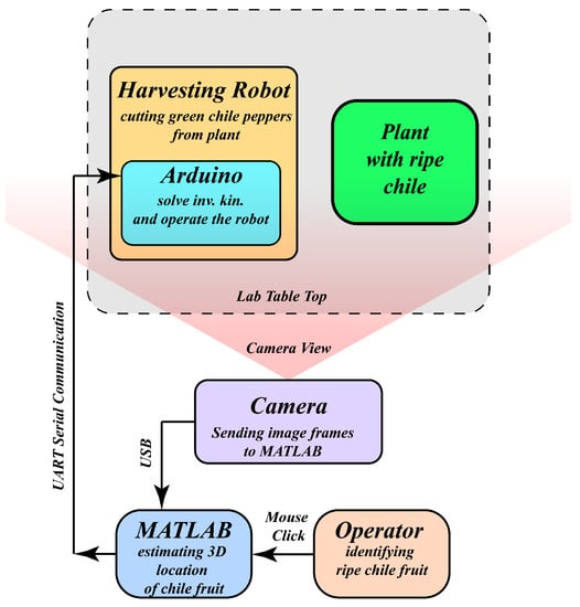
Figure 1.
Harvesting scheme showing all the components.
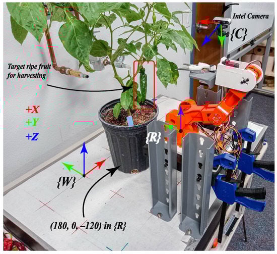
Figure 2.
Lab setup for testing of harvesting robot.
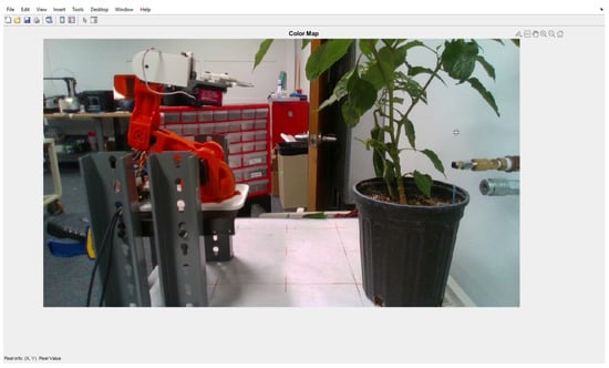
Figure 3.
The image that the operator is seeing and clicks on the ripe chile pepper.
Although the human operator will not exactly choose the best place to be cut, the operator does provide an approximate location for the robot to know where is the connecting point of the fruit to the stem as a reference point. Based on the 3D localization obtained from the image, the robot will move its end-effector to a point (offset from the human operator’s selected point) on the stem determined according to a pre-set offsets in x-y-z direction. These offsets were determined based on the prior analyses of the fruit geometrical features (e.g., average stem length) presented in Section 5. Then, the localization information will be communicated to the Arduino Due board installed on the harvesting robot. This localization information consist of three coordinates data. Given the current joint space position and Cartesian space position of the robot, the arduino program assesses whether this location is within the reachable space of the robot. If the point is in the reachable space, the robot approaches the identified fruit from the outside of the plant, to avoid or minimize collision of the end-effector with any branch or other obstacles within the plant. The cutting mechanism cuts the stem which is connecting the fruit with the plant. The whole operation is considered as a complete harvesting cycle.
3. Harvesting Robot
A systematic design starts from the study of the application requirements, limitations, and valid assumptions. The following subsections give an insight on the performance and limitations of the robot arm being used for this study, with respect to the challenges for chile pepper harvesting.
3.1. Braccio Robotic Arm
Braccio, shown in Figure 4, is a five degrees of freedom (5 DoF), low-cost robot arm used for our preliminary study on the robotic harvesting of chile peppers and proof-of-concept. It is based on DC Servo Motors which are controlled by their internal circuitry in a discrete manner based on the input reference signal send by a micro-controller. In this work, Arduino Due Development Board is used as microcontroller for the hardware. Starting from the base to the end-effector, the joints of the robot arms are named as base, shoulder, elbow, wrist pitch and wrist roll, respectively. All the motors at the joints have a range of motion from 0° to 180° degrees except the shoulder joint (2nd joint), which can only move from 15° to 165°. The limitation of this joint is because of the mechanical design and structural limitations, not the motor’s extreme positions. The maximum reach of the robot arm is 400 mm, while the maximum payload capacity is 150 g for an operating distance of 320 mm and 400 g for minimal operating distance.
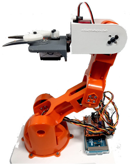
Figure 4.
Braccio robot arm.
3.2. Forward Kinematics
Forward kinematics of the robot is derived in the form of linear homogeneous transformation using Denavit–Hartenberg (D-H) parameters. The joint space is defined so that the zero position of each joint is in the center of its space. It is important to note that the Braccio comes with servo motors, which give an actuator space of 0 to . The joint space selected, following most common notation, is to . The frames assignment is shown in Figure 5. The D-H parameters are written based on the shown frames and tabulated in Table 1. A homogeneous transformation can be written as
where , , , , , and . , , , and are defined in the D-H parameters (see Table 1).
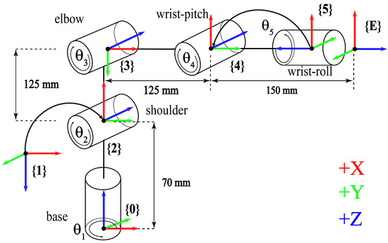
Figure 5.
Braccio schematic, frames, and joints definition.

Table 1.
D-H Parameters of Braccio robot arm.
Table 1.
D-H Parameters of Braccio robot arm.
| i | ||||
|---|---|---|---|---|
| 1 | 180 | 0 | −70 | |
| 2 | 90 | 0 | 0 | |
| 3 | 0 | 125 | 0 | |
| 4 | 0 | 125 | 0 | |
| 5 | 90 | 0 | 0 | |
| E | 180 | 0 | −150 | 0 |
All lengths in mm, while angles are in degrees.
This forward kinematics is used for MATLAB™ simulations and implementation in Arduino.
3.3. Inverse Kinematics
The inverse kinematics of this 5 DoF robot can be written in the geometric form, where the inputs are three coordinate values for position, called as x, y, and z, and two orientation angles called as pitch (denoted as ) and roll (denoted as ). All the joint angles are denoted as , , , , and . The coordinate frames are shown in the Figure 5. The base angle can be determined as
Take r as the distance from the end-effector position in x-y plane (projection on this plane) to the origin of the base frame of the robot, . Defining a new plane comprising of r in x-y plane, and z-, denoted as r-z plane, the solution for next three joints can be solved as a 3-DoF planar robot.
For a specified pitch angle , the location of the 4th joint in r-z plane can be found as and . Now, all the sides of the triangle formed by joint 2, joint 3, and joint 4 are known, so the angles , , and (shown in Figure 6) can be determined by the rule of cosines and the joint angles can be written as
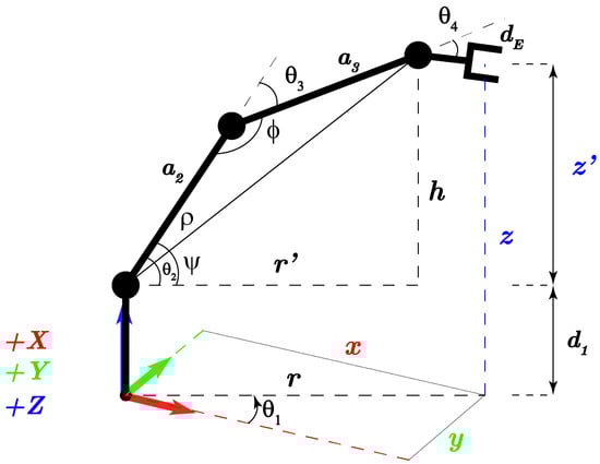
Figure 6.
Geometric representation of the Braccio robot arm for inverse kinematics.
The last angle is independent of position and pitch .
3.4. Reachability and Dexterity
As mentioned earlier, the robot has five degrees of freedom, which limits its dexterity in the yaw orientation, being the rotation about z-, and referred to as . For any position in reachable space, no value other than zero is possible for yaw, when taken in end-effector’s moving frame. Roll, being the rotation about x-, and referred to as , is independent of the end-effector’s position so, any roll orientation is practically possible. The pitch, rotation about y-, denoted as , affects the dexterous space considerably enough, to be studied. It is mostly because of the limitations of the joint movements.
A MATLAB™ program is developed to plot and visualize the reachable workspace of the robot. In this program, only the front half of the robot is plotted, to make the plot more elaborate. The actual workspace is twice (same as the other side of the robot) than what is shown here. The dexterous space of the robot is mainly dependent upon on the pitch angle. For a specified pitch angle, there would be a different dexterous space. Considering these limitations from the hardware, it is needed to define the minimal requirements for the application. Although the ideal pitch angle for the harvesting purpose using Braccio is , but a range of was found practically good enough to harvest a chile pepper from the plant. It is found that the dexterous space for is incredibly small, but, with the flexible range of , the dexterous space is adequate to capture most of the chile peppers from the plant. This will be discussed in detail in the preceding sections. Figure 7 shows the reachable and dexterous space of the Braccio robot arm in the form of the point cloud data. For a better understanding, the planar view is also shown in Figure 7b, where the blue points show the space where the robot is reachable with , and the green points show the space which is reachable with any pitch angle in the range of else . The space covered by magenta points is the overall reachable workspace with any pitch angle .
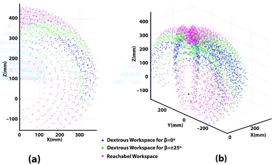
Figure 7.
(a) The workspace in magenta, dexterous space for in blue, and dexterous space for in green, shown in a planar view for a specific base rotation (b) shown in 3D point cloud data for better visualization.
3.5. Repeatability and Accuracy
Repeatability and accuracy are very important parameters to assess the robot’s performance. The repeatability and accuracy test was performed on the robot by giving a target location in 3D space and measuring the actual location of the end-effector where it reaches. It was tested for three different points in the 3D workspace, , , and ; called as point 1, point 2 and point 3, respectively. The three points are selected so that the performance can be assessed in both quadrants, as well as on the x-, which lies on the middle of the robot’s workspace. A total of 33 samples were recorded, having 11 for each point, to assess the inherent performance parameters. The overall average of the difference found in target and reached point is denoted as . The standard deviation for the same point is a metric parameter for repeatability. For each point, standard deviation is denoted as , , and . The Table 2 shows the results.
Table 2.
Accuracy and precision results for Braccio robotic arm.
3.6. Detachment of Chile Fruit
3.6.1. Computer-Aided Design
It was discussed earlier that, for delicate fruit, cutting of pedicle is the most effective technique for detachment from the plant, in terms of minimum damage to the plant. The detachment technique used for harvesting, in this work, is the cutting of stem through sharp edge blades which are actuated with a DC Position Servo motor. This customized cutting mechanism is mounted on Braccio robot arm as the end-effector. The cutter mechanism needs to be designed considering the constraints for size, weight, and mode of operation. These constraints are defined by the capabilities and limitations of Braccio robot arm. The maximum payload capacity of Braccio robot arm is 150 g, so the weight of the designed end-effector was limited to 150 g increment from the original end-effector. Size of the end-effector was also considered so that the minimum collision with the obstacles can be achieved. The torque of the motor held with the gripper of Braccio robot arm is not enough to cut a stem of diameter ranging from 4.7 mm to 6.3 mm. Moreover, the Braccio’s wrist motor is one of the main bottleneck in the limitation of payload capacity. Thus, both motors, the one responsible for roll rotation and the gripper, called M5 and M6, were replaced with metal gear and metal horn servo motors, DS 3218 DC Servo Motor, with the maximum torque of 2 Nm.
As shown in Figure 8a, the cutter is designed such that one blade is fixed with the ground of end-effector and the other blade is moving about a pivot which lies within the body of the blade. This way, the maximum cutting force can be achieved depending on the maximum torque provided by the motor. Additionally, the torque is enhanced by 5.5 times through a set of pinion and gear (with 12 and 54 teeth, respectively) as the transmission method. This helps to drastically increase the cutting success rate. The CAD model of the cutter developed in SolidWorks™ is shown in Figure 8a. The torque at the pivot of the blade come out to be Nm, where is the torque at cutter, and is the maximum torque of the motor. The maximum torque is applied when the motor is operated at 6.0 V.
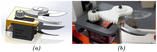
Figure 8.
(a) CAD model of the cutting mechanism. (b) Fabricated cutter installed on the robot arm.
3.6.2. Prototyping and Manufacturing
The designed cutter mechanism was fabricated using a stereolithography (SLA) printer Form 3 (Formlabs, Somerville, MA, USA). For the gears, engineering grade Rigid 400 from Formlabs [34] is used. The blades used for this design are commercially available as replacement blades for gardening pruners. The mounting fixture of the mechanism was designed considering that it should be installed on Braccio robot arm as end-effector. The assembled cutting mechanism installed on the robot’s end-effector is shown in Figure 8b.
4. Vision-Based Fruit Localization
A vision-based fruit localization was used to determine the coordinates of the chile pepper and its stem. Location of an object in camera frame can be estimated in 3D space, given the camera intrinsic and extrinsic. For this purpose, Intel RealSense™ Depth Camera D435i is used, which provides an RGB and depth images. Additionally, the camera is equipped with an Inertial Measurement Unit (IMU), which is used to determine the relative orientation of the camera frame with respect to the world frame . Vision-based identification or classification of the chile fruit is not the scope of this research, so RGB image plays an important role for the user (human operator) to identify chile pods in the image and click on its location with possibly minimal error, as compared to a greyscale depth image. The camera provides 3D image, as well, which may be taken as 3D point cloud data in correlation to every depth image pixel. By combining both RGB and depth image, we can co-relate an image pixel with its 3D location in the camera frame. The location of the targeted point is required to be known in the robot frame . Another frame called the world frame is introduced at a known point in the robot frame. All these frames and the camera setup is shown in Figure 9.
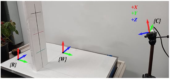
Figure 9.
Actual camera and table setup shown with frames of references.
The robot is placed on a lab bench top with its coordinates shown in Figure 9, and the coordinate frame is denoted as . The plane of this frame is aligned with the bench top. A global frame, called world frame and denoted as , is introduced. Location of camera and the origin of the robot frame can be measured in as there are fixed for the whole operation. Z-axis of frame is perfectly aligned with gravity whether the frame may not be aligned because of inherent inclination of the table and the floor. The rotation matrix describes the camera frame with respect to the world frame. The accelerometer readings (, , and ) were used to solve for the roll and pitch angles ( and ), and we assumed the yaw angle () known due the fixed and known pose of the camera with respect to the benchtop test setup in this study. We externally verified the yaw rotation by aligning the horizontal grid line (see Figure 9).
where and are normalized accelerometer readings and gravity vectors, respectively. Solving for the roll and pitch angles ( and ) gives:
which yields:
substituting these terms back into with yields:
where
In a practical real-world setting with a moving camera, as opposed to the current case, an extra orientation measuring sensor (e.g., electronic compasses or 9-DoF IMU sensor) will be used to calculate the required rotation angles and the rotation matrix.
In Equation (4), , , and are the normalized accelerations with the units of g being the gravitational acceleration. When camera is setup on the tripod, these values can be taken once from the Intel RealSense Viewer software and entered into the MATLAB™ program. The origin point of the world frame was marked on the table and can be seen in the camera image. Using a measuring, the 3D location of camera frame origin can be extracted in the world frame. The homogeneous transformation from frame to frame can be written as
The rotation of the robot frame with respect to the world frame takes into account any tilt in the table top. There is no rotation around the z- because both the frames are on the table top. The table tilt angles and about the x- and y-, respectively, were determined once, using an inclinometer, after the table had setup. This rotation matrix can be written as
where
and where , .
The position of the world frame W is already known in the robot frame. Thus, the transformation is given as:
The combined homogeneous transformation, mapping the camera frame into the robot frame, is obtained as follows: .
Given the position of any point in the camera frame, that can be transformed into the position of the same point in the robot frame. This can be written as:
4.1. Performance of 3D Localization and Camera
A test setup was developed to measure the accuracy of the 3D location estimation. Figure 9 shows the test setup with a known grid marked on the table top. As the measurements are estimated in 3D, there must be some known position elevated from the table’s surface. A grid marked bar was designed with a flat surface which may be placed at any known point in 2D plane to raise its z coordinate value. Note that the vertical bar should be at right angle with the table, but it may not be aligned with gravity vector, as the inclination of table has already been accommodated in the transformations. Following are the possible sources of the error in the 3D localization system. The overall error in the measurement system is given in Table 3.
Table 3.
Error (mm) in 3D location estimation.
4.1.1. Human Operator Error
As mentioned previously, the human operator identifies chile peppers in the image and additionally by clicking on the fruit location it provides a reference point for the robot to position its end-effector for the detachment task. The human operator error, in this case, is due to either the challenge of repeatability of clicking on the same pixel on the image (repeatability) or clicking on a point off the fruit (accuracy). This is very important factor since our robot positioning of stems relies on the reference point location provided by the human operator. Thus, human error is one of the most contributing factor in the integrated error found in this vision-based localization measurement system.
4.1.2. Depth Camera
The depth camera installed does have an inherent error in the depth measurement. This error is unsystematic and needs to be taken as the Original Equipment Manufacturer (OEM) claims. It should be considered that up to 2% error may be there in the measurement of depth when measured in the range of 2 m. Most of these error contributions can be minimized by taking an average of multiple readings. Taking multiple readings is only possible when the image frame or the scene being captured, is stationary. For moving frames, reducing this error can be a challenging task.
4.1.3. Accelerometer
Camera is always in stationary condition for this specific application. In this case, the only acceleration component, that the embedded accelerometer can read is the gravitational vector. The gravitational vector is divided into three Cartesian components, which are normalized and used for orientation of the camera, as given in Equation (4). But there is a known issue with this estimation of orientation. Any rotation about the gravitation vector does not reflect in the orientation matrix. This part was externally verified before taking measurements, by ensuring that each horizontal (along x-axis of the robot frame) grid line in the camera frame should be perfectly horizontal in the frame. This means that all the points on each horizontal line should have same x-pixel value in the image frame. Due to this, there may have some random error in the external verification.
5. Study of Chile Fruit
5.1. Dimensions and Anatomical Features of the Chile Fruit
A data collection and analysis on the size and form factor of the New-Mexico type chile was performed based on 27 chile peppers. The considered parameters are maximum diameter D, projected length L, diameter of the stem d, and the available length of the stem for cutting purpose l. These notations are shown in Figure 10, as well.
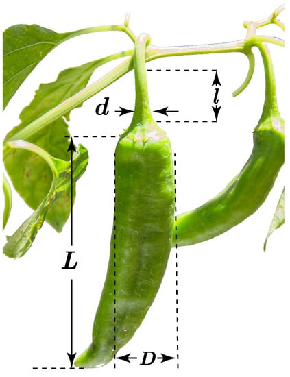
Figure 10.
Dimensions of chile pepper taken into consideration in size data collection.
The analyzed data in form of histogram are shown in the Figure 11. More than 90% of the chile has a diameter in the range of 24 mm to 38 mm with an average of 29.4 mm and the standard deviation of 5.3 mm. Average length of chile pepper is 113.4 mm with a high variation, showing standard deviation of 21.1. Stem diameter is very important to know for designing a cutting mechanism. The average stem diameter was found to be 5.6 mm with the maximum of 7.5 mm. Having more available length of stem means it is easy to reach the chile even with positional errors caused by either mechanical hardware or software. The results show the average available stem length of 22.1 mm with a significant variation of 12.2 mm. However, in some of the anomalous cases, the fruit may not have any available stem. The analysis results are summarized in Table 4.
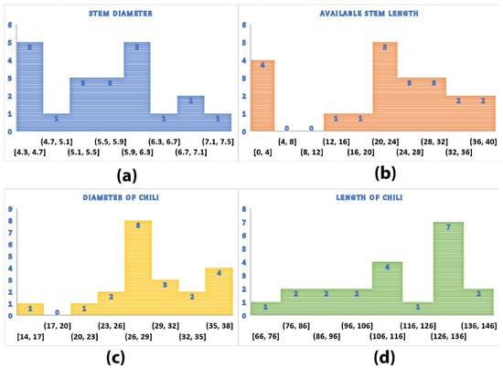
Figure 11.
Histogram of the collected data for (a) diameter of chile pepper, (b) length of chile pepper, (c) diameter of the stem, and (d) available length of the stem.
Table 4.
Variation in chile fruit dimensions and anatomical features.
5.2. Distribution of Chile Fruit on the Plant
The spatial distribution of the chile pepper fruit on the plant was studied as a crucial factor with respect to the robot’s reachable and dexterous space. If the robotic arm was mounted on a mobile robot, then this problem would be seen from some different perspective, but, in the current scenario, it will be discussed based on the fixed location of the robot arm. Considering the bottom center of the chile pot to be , locations of 57 chile peppers were recorded using the 3D location estimation system used for fruit localization in Section 4. The distribution of the chile fruit with respect to the zero location is shown in Figure 12b. Through a MATLAB™-based program, an ideal location for robot is also calculated so that the maximum chile fruit is in the dexterous space (for ) of the robot. This optimum location of the robot was found out to be with respect to the world frame. Figure 12c shows all the chile fruits to be enveloped in the dexterous space of the robot when the robot is located at the optimum location.
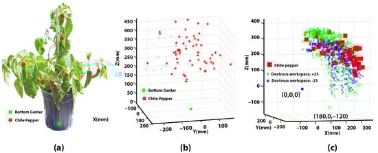
Figure 12.
(a) Spatial distribution shown on physical plant, (b) chile distribution shown with respect to the center of the bottom face of the chile pot, and (c) optimum location of the robot to have maximum chile peppers in the dexterous space.
6. Motion Planning and Harvesting Scheme
This section describes the flow of algorithm followed for harvesting, as shown in Figure 13, along with the motion of the robot in the harvesting operation.
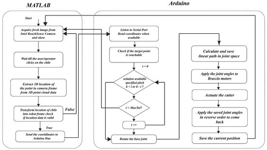
Figure 13.
Algorithm for the harvesting program.
6.1. Motion Planning
Trajectory planning was carried out based on a straight line path in Cartesian space where the pitch orientation of wrist was specified to achieve the desired position and orientation for harvesting chile pepper pods. To generate, verify, and simulate the robot’s motion, a MATLAB™-based simulation program is developed, so that the proposed scheme can always be tested in the simulation. Based on Equation (1), and the inverse kinematics, some commonly used functions, like , are developed. These functions mainly solve the joint angles of the robot for a specific object’s pose in 3D space. Current joint angles and the end-effector’s position and orientation are always kept in the program, so that robot can make a linear trajectory from the current point to the target point in Cartesian space. The preference is to have one kind of inverse kinematics solution for all the intermediate points; therefore, motions in the joint space with drastic changes can be avoided. Figure 14 shows an example of path planning and operation of the Braccio robotic arm in the MATLAB™ simulation for the target point and the initial position . The corresponding joint angles are illustrated in Figure 14b, which verifies the smooth motion of the robotic arm in the joint space, with the joint angles in step time. The resulted path is provided to the Arduino algorithm for operating the actual robotic arm.
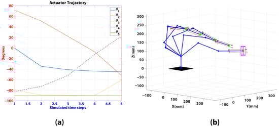
Figure 14.
(a) Actuator trajectory for simulation. (b) MATLAB™ simulation of Braccio with joint angles.
6.2. Harvesting Program
The two-part program runs on MATLAB™ and Arduino simultaneously, as the schematic of the program shows in Figure 13. The MATLAB™ program takes a set of RGB and depth image frame and registers them through the SDK functions. Based on the identification and click on an image pixel, the pixel information is retrieved from the image data and its corresponding depth and 3D point data, from the 3D point cloud built by the SDK function. This 3D location of the chile fruit is in the camera frame. Using Equation (7), the location is transformed into the robot frame. Using serial communication between the MATLAB™ program and Arduino Due board, the location of the chile is communicated to the Arduino, which instructs the robot to reach the specified location and cut the targeted chile.
Arduino program is responsible for the solution of joint angles for the given 3D location. Using inverse kinematics of the robot, this program finds the optimal joint space position of the robot, following a linear trajectory, in the same way as developed in MATLAB™ simulations. Due to the limitations of the Braccio discussed earlier, the dexterous space for one specific pitch angle, , is very small. In the application of chile harvesting, the ideal pitch angle is , but it is acceptable for some range called as tolerance in pitch angle. It has been observed, with experimental studies, that the max tolerance can be up to . An iteration-based algorithm is shown in Figure 13, which solves the solution for the best pitch angle, starting from the ideally required pitch angle. The described harvesting schemes and the operation of the robot was examined in a series of bench top laboratory testing.
7. Results and Discussion
A study has been conducted through a series of experiments to verify the performance, show feasibility of using robotic system, and formulate the potential factors for unsuccessful cases. Generally, performing this study in an indoor (Laboratory) setting has eliminated some of the common challenges in outdoor settings due to the controlled environment, such as working in a structured environment (fixed table and fixed camera view), consistent and controlled light, and disturbances due to wind. Some of the other simplifying assumptions we made in this work include: (1) fruits are fully exposed to the computer vision and the robot (we moderately trimmed the leaves); (2) average geometrical features of chile pepper pods were used for the robot positioning; and (3) the stems are vertically oriented.
The cutting mechanism and technique is proper for the hanging fruits only when the pedicle is separated from other stems and plant objects, and the length of the pedicle is long enough to selectively cut it. As shown in Figure 15a, in some cases, the length of the pedicle is short for the cutting mechanism to selectively cut it for detachment. A higher precision robot may be able to do this job, provided that the width of the cutter is also small enough. Another issue is that, in some cases, there is a big cluster of fruits on the same point in the plant (Figure 15b). First, it is very hard for the vision-based localization system to capture the exact chile pepper’s 3D location; secondly, it is a hard job for the cutting mechanism, as well, to cut the correct chile, in that case. It may increase the damage rate, as well. Another challenging case is shown in Figure 15c, where the chile pepper pedicle (target stem) is very close to the main or sub-branch of the plant. In this case, the robot may damage the plant and, eventually, all the unharvested fruit on that sub branch.
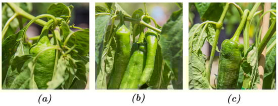
Figure 15.
Challenging cases for robotic harvesting. (a) Chile pepper with almost zero stem available for cutting. (b) A cluster of chile pepper in the same vicinity. (c) A chile pepper with its stem very close of main or sub-branch of the plant.
In addition to the aforementioned limitations, the 5-DoF robot can only reach to chile peppers which is approachable from the center of the robot without any obstacle in pathway. The main stem of the plant is one major obstacle, in such a case, when the robotic manipulator is static on a platform. All the chile pepper which have the main stem of the plant in the pathway of robot, cannot be localized by the robot. Using, the same data of 57 chile pepper, as in Section 5, a MATLAB™ simulation is run to see the effect of the main stem of the plant in the pathway to the chile pepper. Figure 16 shows that, out of 57 chile peppers, 21 (which makes it 36.8%) are in the region which not reachable for the robot because of the stem. The simulation shows that the orientation of the plant may change the percentage value. But, in this study, the orientation of the plant was not intentionally selected to increase the success rate; rather, it was arbitrarily chosen.
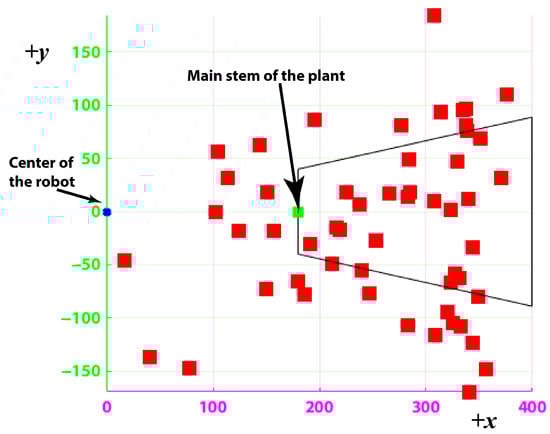
Figure 16.
MATLAB simulation (x-y plane view) of showing chile peppers which are not reachable (in the bounding box) because of the plant stem in the pathway as an obstacle.
Chile harvesting was performed by an image click on the MATLAB™-based program, which finds the location of the chile and sends the coordinates to Arduino. The same test setup shown in Figure 2 was used. The robot was raised 120 mm high reference to the chile pot, through a platform. The chile pots were placed at 180 mm at x-axis in the robot frame. These values were found out as the best optimum location of the robot where it can reach maximum number of chile pepper as per the chile distribution data. Because the camera is fixed at one location, some of the view-blocking leaves were trimmed, in order to see all the chile pepper in the image frame. An example of harvesting operation is shown in Figure 17. For the recorded videos of the operation, please refer to the Supplementary Materials, Video S1.
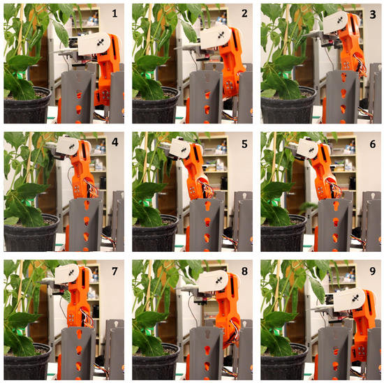
Figure 17.
Harvesting operation of the robot shown in frames.
A number of trials were performed to asses the localization success rate, detachment success rate, harvesting success rate, cycle time, and damage success rate. These performance metric are defined by Reference [10] for harvesting in a canopy. They are interpreted for lab testing as follows:
- Fruit localization success [%]: The number of successfully localized ripe fruit per total number of ripe fruit taken for testing in the lab setup.
- Detachment success [%]: The number of successfully harvested ripe fruit per total number of localized fruit.
- Harvest success [%]: The number of successfully harvested ripe fruit per total number of ripe fruit taken for testing in the lab setup.
- Cycle time [s]: Average time of a full harvest operation, including human identification, localization, and fruit detachment.
- Damage rate [%]: The number of damaged fruit of pedicles per total number of localized ripe fruit, caused by the robot.
Localization is considered correct only if the stem is found to be in the center of two blades of the cutter. Based on 77 ripe fruit taken for harvesting, the summary of harvest testing results are shown in Table 5. For more details and the collected raw data used for these calculation please refer to the Supplementary Materials, Tables S1 and S2.
Table 5.
Results of lab testing of robotic chile pepper harvesting.
Comparison of performance of a robotic harvester to human laborer is a valid point which can indicate whether the use of robot is effective/efficient and economical or not. However, to the best of our knowledge, direct information regarding hand-pick harvesting performance indicators has not been collected. Although, based on our personal experience in the lab, the human clipping, for example, is faster but taking into account the burden of this repetitive task and the capability of robots to perform repetitive tasks in a longer period of time compared to human laborer, the obtained 7 s cycle is justified. Additionally, the average cycle time for different harvesting robots, reported in Reference [10], is 33 s with a large range of 1 to 277 s, which makes our robotic harvester’s cycle time performance to be in a reasonable range.
Based on the previous studies, in this matter, 6.9% is an acceptable rate for fruit damages using mechanized/robotic harvesting. Bac et al. [10] reported on average the fruit damage rate for robotic harvesters (for different crops) is 5% with the low of 0% and high of 13%. Particularly, the fruit damage rate was reported for chile pepper mechanized harvester as low as 7% to 11% which is stated as “acceptably low” [9]. In some other aggressive mechanized harvesters, the fruit damage rate was reported as high as 20% [8]. In our future work, we will use in-hand visual servoing and related motion planning to improve this harvesting factor.
In this study, the localization of stem was carried out by a combination of the human operator fruit detection and robot pre-motion planning algorithm. Therefore, the real localization which must be vision-based had not be implemented. In this study, we defined the localization in a slightly different way, and it was considered correct only if the stem is found to be in the center of two blades of the cutter. As it is mentioned, this is the result of the fruit identification by the human operator and other pre-adjustment in the robot motion planning based on our knowledge from the fruit geometrical analysis section. Despite the simplified assumptions, this task was facing a higher rate of failure compared to the other factors due to more complexity of stem and plant structure; please refer to Figure 15. One solution to resolve this issue and improve the rate is to use an in-hand camera (camera mounted at the wrist) to provide real-time and close-up information about the stem geometrical feature, and then the robot would be able to perform on-the-fly adjustment to position the cutter in an optimal position for a successful detachment.
The obtained results for robotic harvesting using a 5-DoF robot show promising for future studies based on the presented feasibility study and the observed challenges, which are specific to the case of chile pepper harvesting. The results indicate that using a robotic arm with more degrees-of-freedom could improve the chile pepper harvesting performance. Moreover, the outcomes of this study indicate the importance of mobility of manipulator to achieve higher harvesting rate. For example, if the same manipulator is mounted on top of a mobile robot, then it can reach all the plants from all sides, which would increase the localization and harvesting success rate. To achieve fully autonomous harvesting robot for chile pepper, our overarching goal, integration of two major components into the current system are needed. First is computer vision which requires fruit identification and localization. As many robotic harvesting applications rely on color differences, it will be critical to establish features capable of distinguishing between the green foliage of the chile plants and the green chile pods themselves, as in Figure 3. Work in detection of other crops with a similar identification challenge, such as green bell peppers [35,36] and cucumber [37], provides some guidance on identifying green fruits based on other features (e.g., slight variations in color or texture (i.e., smoothness) or spectral differences in NIR). Leveraging machine learning and the capabilities of convolutional neural networks (CNNs), which have shown excellent performance in image classification and segmentation, could overcome this challenge. Second, from the standpoint of robot operation, using more advance motion planning and control algorithms are required to perform them.
8. Conclusions
This paper presents a feasibility study on the robotic harvesting for chile pepper, in a laboratory setting, using a 5-DoF serial manipulator. A simple and easy to develop 3D location estimation system was developed with considerably minimal mean error which can be efficiently used for various research applications which involve data logging. The estimation system is designed linear, which does not consider affinity and other hardcore computer vision theories, in the trade-off of a considerable effort to setup for each data logging session. The first of its nature, a detailed study is performed on the chile pepper plant and fruit to study the feasibility and challenges for robotic harvesting of chile pepper, which is immensely needed for researchers who are contributing in this field. Based on the collected data, it was shown that an optimum location of the robotic arm can be extracted. For Braccio robot arm, the optimum location was found to be , with respect to the world frame. The forward and inverse kinematics of Braccio robot was derived for workspace analysis and motion planning. A chile pepper harvesting robot is developed with a customized cutting mechanism, in which its performance was examined in a series of in-laboratory harvesting tests. The developed harvesting robot showed promising results with localization success rate, detachment success rate, harvest success rate, damage rate, and cycle time of 37.7%, 65.5%, 24.7%, 6.9%, and 7 s, respectively. With this study, it is shown that the chile pepper harvesting is feasible with robotics, and, in the future, more efforts should be put into this area by the researchers. By eliminating the inherent drawbacks and limitations in the presented system, the success rate can be increased.
Supplementary Materials
The following are available online at https://www.mdpi.com/article/10.3390/robotics10030094/s1, Table S1: Harvesting results, Table S2: Chile peppers’ 3D location, Video S1: Harvesting supplementary videos.
Author Contributions
Conceptualization, M.U.M. and M.H.-J.; methodology, M.U.M. and M.H.-J.; software, M.U.M. and M.H.-J.; validation, M.U.M.; formal analysis, M.U.M.; investigation, M.U.M.; resources, M.H.-J.; data curation, M.U.M.; writing—original draft preparation, M.U.M. and M.H.-J.; writing—review and editing, M.H.-J.; visualization, M.U.M. and M.H.-J.; supervision, M.H.-J.; funding acquisition, M.H.-J. All authors have read and agreed to the published version of the manuscript.
Funding
This work is supported by a grant (award number 2021-67021-34203) from USDA/NIFA and a seed funding from the NMSU Center of Excellence in Sustainable Food and Agricultural Systems (CESFAS) program.
Institutional Review Board Statement
Not applicable.
Informed Consent Statement
Not applicable.
Data Availability Statement
The data presented in this study are available in the Supplementary Materials provided in this article.
Conflicts of Interest
The authors declare no conflict of interest.
Abbreviations
The following abbreviations are used in this manuscript:
| DoF | Degrees of freedom |
| D-H | Denavit–Hartenberg |
| DC | Direct current |
| CAD | Computer aided design |
| SLA | Stereolithography |
| 3D | Three-dimensional |
| SD | Standard deviation |
| SDK | Software development kit |
| RGB | Red-Green-Blue |
References
- Bosland, P.W.; Bailey, A.L.; Cotter, D.J. Growing Chiles in New Mexico; Guide H-New Mexico State University, Cooperative Extension Service (USA): Las Cruces, NM, USA, 1991. [Google Scholar]
- Bosland, P.W.; Walker, S. Growing Chiles in New Mexico [Guide H-230]; Guide H-New Mexico State University, Cooperative Extension Service (USA): Las Cruces, NM, USA, 2014. [Google Scholar]
- Taylor, J.E.; Charlton, D.; Yúnez-Naude, A. The end of farm labor abundance. Appl. Econ. Perspect. Policy 2012, 34, 587–598. [Google Scholar] [CrossRef]
- Hertz, T.; Zahniser, S. Is there a farm labor shortage? Am. J. Agric. Econ. 2013, 95, 476–481. [Google Scholar] [CrossRef] [Green Version]
- 2020 New Mexico Chile Production; Technical Report; USDA National Agriculture Statistics Service: Washington, DC, USA, 2021.
- Russo, V.M. Peppers: Botany, Production and Uses; CABI Publishing: Wallingford, UK, 2012; pp. 1–280. [Google Scholar] [CrossRef]
- Miles, J.; Hinz, W.; Pike, W. Development of a Mechanism for Picking Chile Peppers. Trans. ASAE 1978, 21, 419–0421. [Google Scholar] [CrossRef]
- Funk, P.A.; Walker, S.J.; Herbon, R.P. A systems approach to chile harvest mechanization. Int. J. Veg. Sci. 2011, 17, 296–309. [Google Scholar] [CrossRef]
- Funk, P.A.; Walker, S.J. Evaluation of Five Green Chile Cultivars Utilizing Five Different Harvest Mechanisms. Appl. Eng. Agric. 2010, 26, 955–964. [Google Scholar] [CrossRef]
- Bac, C.W.; Van Henten, E.J.; Hemming, J.; Edan, Y. Harvesting Robots for High-value Crops: State-of-the-art Review and Challenges Ahead. J. Field Robot. 2014, 31, 888–911. [Google Scholar] [CrossRef]
- Bechar, A.; Vigneault, C. Agricultural robots for field operations: Concepts and components. Biosyst. Eng. 2016, 149, 94–111. [Google Scholar] [CrossRef]
- Bonadies, S.; Lefcourt, A.; Gadsden, S.A. A survey of unmanned ground vehicles with applications to agricultural and environmental sensing. Autonomous air and ground sensing systems for agricultural optimization and phenotyping. Int. Soc. Opt. Photonics 2016, 9866, 98660Q. [Google Scholar]
- Zhao, D.-A.; Lv, J.; Ji, W.; Zhang, Y.; Chen, Y. Design and control of an apple harvesting robot. Biosyst. Eng. 2011, 110, 112–122. [Google Scholar]
- Feng, Q.; Zou, W.; Fan, P.; Zhang, C.; Wang, X.; Xiong, Y.; From, P.J.; Isler, V.; Davidson, J.R.; Bulanon, D.M.; et al. Fruit detection system and an end effector for robotic harvesting of Fuji apples. Agric. Eng. Int. CIGR J. 2019, 12, 203–210. [Google Scholar] [CrossRef]
- Liu, T.H.; Zeng, X.R.; Ke, Z.H. Design and prototyping a harvester for litchi picking. In Proceedings of the 2011 Fourth International Conference on Intelligent Computation Technology and Automation, Shenzhen, China, 28–29 March 2011; Volume 2, pp. 39–42. [Google Scholar] [CrossRef]
- Baeten, J.; Donné, K.; Boedrij, S.; Beckers, W.; Claesen, E. Autonomous fruit picking machine: A robotic apple harvester. Springer Tracts Adv. Robot. 2008, 42, 531–539. [Google Scholar] [CrossRef] [Green Version]
- Tanigaki, K.; Fujiura, T.; Akase, A.; Imagawa, J. Cherry-harvesting robot. Comput. Electron. Agric. 2008, 63, 65–72. [Google Scholar] [CrossRef]
- Aljanobi, A.A.; Al-Hamed, S.A.; Al-Suhaibani, S.A. A Setup of Mobile Robotic Unit for Fruit Harvesting. In Proceedings of the 19th International Workshop on Robotics in Alpe-Adria-Danube Region, RAAD 2010-Proceedings, Budapest, Hungary, 24–26 June 2010; pp. 105–108. [Google Scholar] [CrossRef]
- Hayashi, S.; Ganno, K.; Ishii, Y.; Tanaka, I. Robotic Harvesting System for Eggplants. Jpn. Agric. Res. Q. JARQ 2002, 36, 163–168. [Google Scholar] [CrossRef] [Green Version]
- Davidson, J.; Bhusal, S.; Mo, C.; Karkee, M.; Zhang, Q. Robotic Manipulation for Specialty Crop Harvesting: A Review of Manipulator and End-Effector Technologies. Glob. J. Agric. Allied Sci. 2020, 2, 25–41. [Google Scholar] [CrossRef]
- Gunderman, A.L.; Collins, J.; Myer, A.; Threlfall, R.; Chen, Y. Tendon-Driven Soft Robotic Gripper for Berry Harvesting. arXiv 2021, arXiv:2103.04270. [Google Scholar]
- Ceccarelli, M.; Figliolini, G.; Ottaviano, E.; Mata, A.S.; Criado, E.J. Designing a robotic gripper for harvesting horticulture products. Robotica 2000, 18, 105–111. [Google Scholar] [CrossRef] [Green Version]
- Kultongkham, A.; Kumnon, S.; Thintawornkul, T.; Chanthsopeephan, T. The design of a force feedback soft gripper for tomato harvesting. J. Agric. Eng. 2021, 52. [Google Scholar] [CrossRef]
- Hohimer, C.J.; Wang, H.; Bhusal, S.; Miller, J.; Mo, C.; Karkee, M. Design and field evaluation of a robotic apple harvesting system with a 3d-printed soft-robotic end-effector. Trans. ASABE 2019, 62, 405–414. [Google Scholar] [CrossRef]
- Bulanon, D.M.; Kataoka, T. Fruit Detection System and an End Effector for Robotic Harvesting of Fuji Apples; American Society of Agricultural and Biological Engineers: St. Joseph, MI, USA, 2010. [Google Scholar]
- Van Henten, E.J.; Hemming, J.; Van Tuijl, B.; Kornet, J.; Meuleman, J.; Bontsema, J.; Van Os, E. An autonomous robot for harvesting cucumbers in greenhouses. Auton. Robot. 2002, 13, 241–258. [Google Scholar] [CrossRef]
- Van Henten, E.; Van’t Slot, D.; Hol, C.; Van Willigenburg, L. Optimal manipulator design for a cucumber harvesting robot. Comput. Electron. Agric. 2009, 65, 247–257. [Google Scholar] [CrossRef]
- Liu, J.; Li, P.; Li, Z. A multi-sensory end-effector for spherical fruit harvesting robot. In Proceedings of the IEEE International Conference on Automation and Logistics, ICAL 2007, Jinan, China, 18–21 August 2007; pp. 258–262. [Google Scholar] [CrossRef]
- Jia, B.; Zhu, A.; Yang, S.X.; Mittal, G.S. Integrated gripper and cutter in a mobile robotic system for harvesting greenhouse products. In Proceedings of the 2009 IEEE International Conference on Robotics and Biomimetics, ROBIO 2009, Guilin, China, 19–23 December 2009; pp. 1778–1783. [Google Scholar] [CrossRef]
- Reed, J.; Miles, S.; Butler, J.; Baldwin, M.; Noble, R. AE—Automation and emerging technologies: Automatic mushroom harvester development. J. Agric. Eng. Res. 2001, 78, 15–23. [Google Scholar] [CrossRef]
- Foglia, M.M.; Reina, G. Agricultural robot for radicchio harvesting. J. Field Robot. 2006, 23, 363–377. [Google Scholar] [CrossRef]
- Sakai, S.; Iida, M.; Osuka, K.; Umeda, M. Design and control of a heavy material handling manipulator for agricultural robots. Auton. Robot. 2008, 25, 189–204. [Google Scholar] [CrossRef] [Green Version]
- Wei, J.; Yi, D.; Bo, X.; Guangyu, C.; Dean, Z. Adaptive variable parameter impedance control for apple harvesting robot compliant picking. Complexity 2020. [Google Scholar] [CrossRef]
- 3D Printing Materials: Engineering Resins|Formlabs. Available online: https://formlabs.com/ (accessed on 21 July 2021).
- Moghimi, A.; Aghkhani, M.H.; Golzarian, M.R.; Rohani, A.; Yang, C. A robo-vision algorithm for automatic harvesting of green bell pepper. In Proceedings of the 2015 ASABE Annual International Meeting, American Society of Agricultural and Biological Engineers, New Orleans, LA, USA, 26–29 July 2015; p. 1. [Google Scholar]
- Kitamura, S.; Oka, K. Recognition and cutting system of sweet pepper for picking robot in greenhouse horticulture. In Proceedings of the IEEE International Conference Mechatronics and Automation, Niagara Falls, ON, Canada, 29 July–1 August 2005; Volume 4, pp. 1807–1812. [Google Scholar]
- Yuan, T.; Li, W.; Feng, Q.; Zhang, J. Spectral Imaging for Greenhouse Cucumber Fruit Detection Based on Binocular Stereovision; American Society of Agricultural and Biological Engineers: Pittsburgh, PA, USA, 2010; p. 1. [Google Scholar]
Publisher’s Note: MDPI stays neutral with regard to jurisdictional claims in published maps and institutional affiliations. |
© 2021 by the authors. Licensee MDPI, Basel, Switzerland. This article is an open access article distributed under the terms and conditions of the Creative Commons Attribution (CC BY) license (https://creativecommons.org/licenses/by/4.0/).