Abstract
Fabrication imperfections strongly influence the functioning of Micro-Electro-Mechanical Systems (MEMS) if not taken into account during the design process. They must be indeed identified or precisely predicted to guarantee a proper compensation during the calibration phase or directly in operation. In this work, we propose an efficient approach for the identification of geometric uncertainties of MEMS, exploiting the asymptotic homogenization technique. In particular, the proposed strategy is experimentally validated on a MEMS filter, a device constituted by a complex periodic geometry, which would require high computational costs if simulated through full-order models. The complex periodic structure is replaced by an equivalent homogeneous medium, allowing a fast optimization procedure to identify imperfections by comparing a simplified analytical model with the experimental data available for the MEMS filter. The actual over-etch, obtained after the release phase, and the electrode offset of a fabricated MEMS filter are effectively identified through the proposed strategy.
1. Introduction
The rapid spread of high-performance Micro-Electro-Mechanical Systems (MEMS) in consumer applications, in the automotive industry, in virtual/augmented reality and in the internet of things [1,2,3] requires improved design methods, new fabrication strategies and efficient control procedures.
In particular, a lot of work has been devoted to improving MEMS fabrication processes [4] and to controlling imperfections that are inevitably present [5,6,7,8]. Despite the increasing effort in such topics, MEMS fabrication process imperfections still represent unknowns for MEMS designers and a significant limitation for devices’ performance and reliability. In [6,9], for example, the effect of process-induced uncertainties on the performance of MEMS devices is addressed, while in [10], it is demonstrated how fabrication imperfections impact energy loss through mechanical mode coupling. In [11], the imperfections coming from both the fabrication and assembly/packaging of Radio-Frequency MEMS devices are studied and categorized, while in [12], sensitivity analyses are proposed to study the effect of geometric and material uncertainties on the performance of MEMS resonators.
The direct experimental measurement of fabrication imperfections is very complex and time-consuming due to the scale of the devices. For this purpose, optical/scanning electron microscopy [13] or laser interferometry [14] is usually employed. However, these optical techniques cannot provide significant information on the fabrication imperfections of the final geometry of the device since MEMS are typically encapsulated and consequently not directly accessible through visual inspection. On the other hand, electrostatic measurements represent a very powerful experimental technique, but, while affected by uncertainties, they do not allow for the direct quantification of fabrication process imperfections.
Analytical or numerical models able to predict the correct functioning of MEMS devices also in the presence of fabrication process imperfections are fundamental for design, as evidenced in [15] for a tuning-fork gyroscope or in [16] for an electrostatically actuated microbeam resonator.
In [17], a theory to predict the strength of microstructures in the presence of defects is proposed and good agreement with experimental results is demonstrated; in [18], the effect of etch holes on ferromagnetic MEMS is modelled, while in [19], Monte Carlo analyses are combined with finite element method (FEM) simulations to investigate the effect of the grain morphology and orientation on the effective elastic properties of polysilicon structures usually employed in MEMS.
Inverse identification of the unknown mechanical, geometric and material parameters through the combination of experiments and finite element models seems a promising strategy, but its huge computational cost arising from the use of full-order FEM simulations makes it hardly applicable to the complex structures typical of MEMS devices. To overcome such limitations, parametric model order reduction techniques based on the combination of the proper orthogonal decomposition and the kriging metamodeling have been recently proposed in [20,21].
An alternative, new and promising strategy is proposed and applied in this work to reduce the computational cost of the inverse identification of fabrication imperfections in geometrically complex MEMS. Our proposal makes use of asymptotic homogenization. The two-scale homogenization is a mathematical tool that provides explicit expressions of the effective properties of periodically heterogeneous materials, under the hypothesis of linearity and scale separation [22,23]. The method has been widely employed in solid mechanics to study the static and dynamic behavior of composite materials and metamaterials [24,25,26,27], but seldom applied to MEMS, to the best of authors’ knowledge. In this work, we combine an analytical model with the asymptotic homogenization technique to identify two typical geometric unknowns of capacitive devices: the electrode offset and the over-etch. The electrode offset is here defined as the discrepancy between nominal and after-fabrication gaps between movable components, i.e., rotor, and fixed electrodes, i.e., stators. The over-etch is instead defined as the deviation from the nominal geometric dimensions of the fabricated mechanical structure. Such discrepancy is an inevitable consequence of the acid attack exploited during the MEMS fabrication to selectively remove the oxide deposited below the polysilicon and to consequently obtain suspended mechanical structures able to move with respect to the substrate. The acid indeed penetrates in the polysilicon structure from the free edges and reduces their in-plane dimensions by a quantity that is referred to as over-etch. Its actual value is unknown and strongly affects the behavior of the device, especially when elements with small in-plane dimensions are present, e.g., suspension springs. In the present work, we implement a proper optimization procedure based on the minimization of the difference between modeling predictions (analytical model plus homogenization) and experimental data coming from electro-mechanical tests.
The paper is organized as follows. The asymptotic homogenization technique is introduced in Section 2 and applied to a MEMS electrically tunable mechanical filter in Section 3 to identify an equivalent continuum. In Section 4, the new identification procedure of over-etch and electrode offset is detailed and then applied to the MEMS filter previously studied; conclusions are finally summarized in Section 5.
2. Asymptotic Homogenization
Numerical analyses of periodic media often represent a huge computational burden, especially when the size ℓ of the microstructure is very small with respect to the macroscopic dimension L of the body. In such a case, i.e., when , the problem can be studied by employing two-scale asymptotic homogenization, which is a mathematical tool that provides the effective homogenized properties of a periodic medium.
We consider a single-phase linear-elastic body , such as the one shown in Figure 1a, which is constructed by a periodic repetition of a unit cell , shown in Figure 1b, in which only a subset is filled by the material. The geometry of the unit cell is completely free at this stage; a specific example will be provided in the following section (Figure 2, right panel).
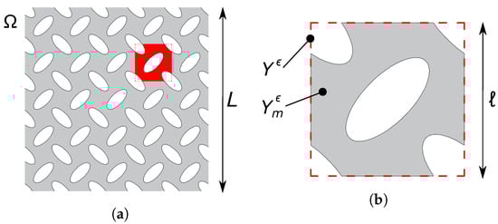
Figure 1.
(a) Single-phase heterogeneous medium with periodic structure. (b) Close-up view of its unit cell.
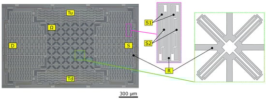
Figure 2.
SEM immage of the MEMS structure (left) with a close-up view of the stators S1, S2 (mid) and the auxetic unit cell (right).
In the small strains and displacements hypothesis, the static equilibrium of the periodic media is governed by the differential equations
where are the body forces, is the displacement field, is the symmetric part of the gradient of and is the fourth-order elastic stiffness tensor of the constituent material.
Using the standard argument of asymptotic homogenization [22,23], we denote by the macroscopic variable and by the microscopic one, which lives in the re-scaled unit cell . The assumed material periodicity gives
while body forces can be non-uniform and read
The solution of (1) is searched by developing the displacement with respect to in the form
where all the fields on the right-hand side of Equation (4) are defined on and are periodic with respect to . For any vector function of and , we will denote by a subscript and the partial derivative with respect to and ; for instance, and will denote the symmetric gradients of with respect to and , respectively.
It is possible to prove—see [23] for the full derivation—that the 0-th order displacement only depends on the macroscopic variable, i.e., , and that the effective equilibrium equation is given by
In Equation (5), is the homogenized stiffness tensor of the periodic media, whose components are evaluated as
being the unit vector in the i-th direction, ⊙ the symmetric tensorial product and the solution of the cell problem
The field represents the elastic displacement of the re-scaled unit cell, up to a rigid body motion, when it is subjected to periodic boundary conditions and the uniform eigenstrain .
As can be seen from (6), the effective stiffness tensor possesses all the minor and major symmetries, i.e., . However, it should be noticed that, in general, is anisotropic even if the constituent material is isotropic.
Finally, in Equation (5), are the homogenized body forces, which are given by
3. MEMS Filter
3.1. Mechanical Design
The innovative MEMS electrically tunable mechanical filter recently proposed in [28,29] is here employed to demonstrate the efficiency of the proposed fabrication imperfection identification procedure.
A scanning electron microscopy (SEM) image of the MEMS filter, fabricated through surface micromachining by the STMicroelctronics Thelma© (Thick Epitaxial Layer for Micro-Gyroscopes and Accelerometers) process [3], is shown in Figure 2. The device consists of a central structure made by a 5 × 5 periodic repetition of the auxetic unit cell reported in the right-hand close-up schematic view of Figure 2, and four external frames , , S and D rigidly connected to the central structure through thick beams and suspended to the substrate through folded springs.
Electrodes for the electrostatic push–pull actuation and differential readout are located inside the four frames according to the scheme shown in Figure 2 (middle panel). The central part of the device represents an example of a two-dimensional periodic medium, as studied in Section 2; hence, homogenization will be applied to this part. The four external frames are also “quasi-periodic” (i.e., the constituent cells slightly vary in space), but they will not be homogenized as their geometry is simple and their deformation in operation is negligible. A coarse mesh can be then employed to discretize external frames without losing accuracy and simultaneously not affecting the overall computational cost of the FEM simulation.
3.2. Homogenization of the Auxetic Core
The inner core of the MEMS structure is here analyzed through the asymptotic homogenization. In particular, after solving the cell problems (7), the effective properties of the media are computed from Equation (6). Figure 3 shows the solution of the three cell problems in which uniform eigenstrains are applied within the unit cell: (a) normal horizontal, (b) normal vertical and (c) angular eigenstrain.
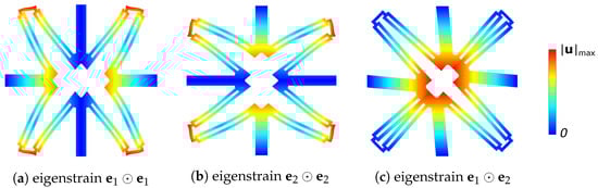
Figure 3.
Contour of the displacement magnitude over the (magnified) deformed shape of the solution of cell problems (a) , (b) and (c) .
The in-plane anisotropy of the auxetic core can be visualized by computing the effective in-plane Young’s modulus and Poisson’s ratio as a function of the stretching direction , being the angle with respect to the horizontal direction. Introducing the transversal direction —see [30] for further details—one has
where is the effective compliance of the periodic media, i.e., the inverse tensor of .
The homogenized properties are shown in the polar plots of Figure 4 as a function of for different values of the over-etch. As expected, for increasing values of the over-etch, the auxetic core of the MEMS filter becomes more and more compliant since monotonically decreases. When the direction of stretching is mainly horizontal or vertical, the inner core exhibits an auxetic behavior (), which is quite independent of the over-etch.
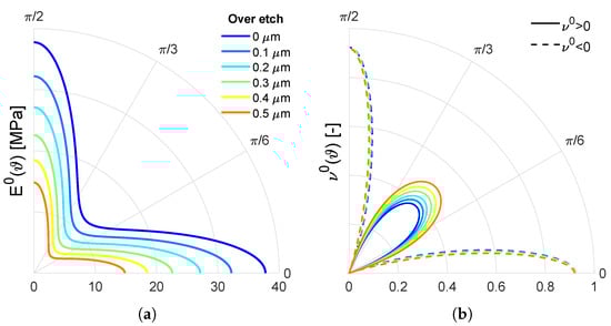
Figure 4.
Polar plots of the homogenized Young’s modulus (a) and Poisson’s ratio (b) as a function of for different values of the over-etch. Negative values of are indicated with dashed lines.
3.3. Validation of Effective Properties
The asymptotic homogenization technique can be employed to reduce the computational burden of numerical analyses involving periodic linear-elastic media, without a significant loss in terms of accuracy.
To validate the homogenized properties of the auxetic core of the MEMS structure of Figure 2, we compare the result of finite element analyses (FEA) obtained in the case of the real geometry and those obtained by replacing the inner core with an equivalent homogeneous medium.
We simulate the case in which the left and the right frames of the MEMS structure are displaced outwards of in the horizontal direction. The FEA are carried out in the case of the MEMS nominal geometry with the commercial finite element software COMSOL Multiphysics.
As discussed in [31], a fine discretization is required to correctly reproduce the bending of the thin elements constituting the auxetic unit cells and the anchoring springs. The mesh employed for the real geometry is composed of 1,600,000 quadratic serendipity tetrahedral elements. When the inner core is replaced by the effective homogenized medium, a coarser mesh can be used and the number of elements is reduced to 600,000.
Figure 5 shows the contours of the horizontal (a,b) and vertical (c,d) displacement fields of the inner core of the MEMS structure for the real and the homogenized model. The fields are non-uniform due to the fact that only the three central cells are attached to the frames. Due to the auxetic behavior, the structure expands in the vertical direction. The homogenization approach allows a reduction in the computational time of 90% and a 4% error ( FEM with actual geometry and FEM with homogenized medium) in terms of vertical displacement of the top/bottom frame.
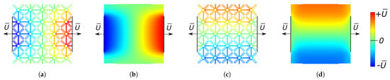
Figure 5.
Contours of the horizontal (a,b) and vertical (c,d) displacement of the MEMS auxetic core (a,c) and the corresponding homogenized medium (b,d).
4. Identification of Geometric Uncertainties
4.1. Experimental Results
To experimentally validate the hybrid modeling reduction strategy, an electrical characterization in the static regime of the push–pull parallel-plate capacitors located in the external frames of the auxetic MEMS device is performed. Figure 6a shows the block diagram of the experimental setup implemented to perform the electrical characterization of the MEMS device.
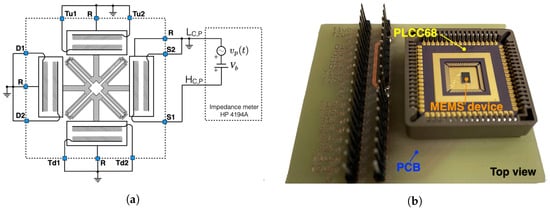
Figure 6.
(a) Block diagram of the experimental setup employed for the static characterization of the auxetic MEMS device; (b) image of tailored printed circuit board (PCB) containing the MEMS device housed in a PLCC68 package.
The capacitance between each distinctive stator terminal, , , , , , , and , and the common rotor terminal R is measured by exploiting the impedance meter HP4194A by applying a proper sinusoidal probing signal and a tunable DC-bias voltage . Specifically, Figure 6a reports the experimental configuration used to measure the capacitance , i.e., the capacitance between terminals and R. In the reported configuration, the probing signal and the DC-bias voltage is applied between terminals and R while keeping all other terminals grounded to avoid unwanted induced electrostatic forces. The bias voltage is tuned within the range 0–12 V with a step size of V to induce a tunable electrostatic force between the parallel plates . We suitably set the maximum value of to prevent the pull-in effect and the root mean square value of the amplitude to 50 mV to produce a negligible electrostatic force compared to the one induced by . The frequency is chosen equal to 200 kHz to avoid mechanical resonances of the MEMS structure. The first translational/auxetic modes actuable through the electrodes located on the D (or S) frame are indeed in the frequency range 16 kHz–60 kHz.
A similar experimental configuration is implemented to measure all other capacitances, i.e., , , , , , and . The top view of the tailored printed circuit board (PCB) developed for the static characterization of the auxetic MEMS device bonded in the 68-pin plastic-leaded-chip-carrier (PLCC68) package is reported in Figure 6b.
The experimental capacitance–voltage curves between the rotor and each one of the stators of the MEMS structure are reported in Figure 7 with dots, having defined .
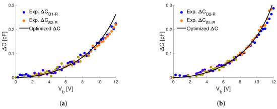
Figure 7.
Capacitance–voltage curves, between the rotor and the different stators (a) Exp. ; Exp. , (b) Exp. ; Exp. , (c) Exp. ; Exp. , (d) Exp. ; Exp. , obtained experimentally (dotted), and the optimal analytical ones (black continuos).
Due to the symmetries of the MEMS nominal geometry, in the absence of any non-symmetric imperfection, the experimental curves in Figure 7a,c should be identical to those of Figure 7b,d (respectively). As can be seen, this is not the case for Figure 7a,b, since, at a given bias voltage, the experimental values of and are lower with respect to and . This effect can be explained by an initial gap between the rotor and the stators that is larger than the one between the rotor and the stators , i.e., arguing that the rotor is rigidly shifted in the horizontal direction with respect to the substrate. This shift can actually occur due to geometric imperfection and/or to the presence of pre-stresses in the suspension springs.
4.2. Optimization Procedure
In this work, we focus on the identification of only two possible geometric uncertainties of a MEMS device, but the same approach can be applied also in the case of more fabrication imperfections. The first one is the over-etch , which significantly modifies the MEMS geometry and the stiffness of its components. The second parameter is a possible rigid horizontal shift of the rotor R with respect to the substrate, which leads to asymmetric gaps between the stators of the left and right frames.
When measuring the capacitance–voltage relationship between the rotor R and a stator , with or , the functioning of the MEMS structure can be described by the simplified scheme shown in Figure 8a. The left plate represents the stators fixed on the substrate, while the right one represents the rotor R, which is anchored to the substrate by means of a spring.
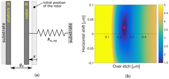
Figure 8.
(a) Schematic representation of the analytical model; (b) contour of the error as a function of the over-etch and horizontal shift.
The stiffness of the spring represents the linear-elastic equivalent stiffness of the MEMS frame where the stators are located. These values can be evaluated by FEA, as a function of the over-etch , exploiting the homogenization of the inner auxetic core; see [31] for details. For example, the equivalent stiffness of the D frame is evaluated as the ratio of the applied uniform horizontal force on the frame and its (average) horizontal displacement, while the stiffness of the frame is evaluated as the ratio between the uniform vertical force on the frame and the corresponding vertical displacement.
In the hypothesis that all capacitors in the MEMS device act as parallel plates, which is quite reasonable since the dimensions of the capacitors are far larger than their distance, the capacitance between and R can be evaluated as
where is the vacuum permittivity, is the total surface of the plates, x is the displacement of the rotor and is the initial gap between the plates. This latter can be expressed as a function of the fabrication imperfections here under investigation as
where is the nominal initial gap between the plates. The attractive electrostatic force acting on the rotor can be evaluated as
where the simplification is justified by the small amplitude of the probing signal employed in the experimental tests.
Enforcing the balance between the electrostatic force (12) and the restoring elastic force , one obtains
which defines implicitly the analytical capacitance–voltage relation between the stators and the rotor R, as a function of and , where .
Once the analytical and experimental capacitances are obtained from Equation (13) and measurements, respectively, the optimal over-etch and horizontal shift are chosen as those values that minimize the relative error
where is the -norm of .
4.3. Results
Considering reasonable intervals of the uncertainty parameters, e.g., m and m, one can evaluate the relative error (14) between the analytical and experimental capacitance curves. Note that the error should be evaluated in a limited voltage interval, e.g., between 0 V and 10 V, to avoid nonlinear phenomena that may occur at high voltage and that are not taken into account in the equivalent stiffness analytical model.
Figure 8b shows the contour of the relative error as a function of the over-etch and the horizontal shift. In particular, the yellow indicates the region where , while the red marker indicates the minimum of the error, which occurs at m and m. The optimal over-etch is in good agreement with typical values available for the fabrication process employed for the MEMS device under study [32].
The analytical capacitance–voltage curves associated with the optimal values of over-etch and horizontal shift are shown in Figure 7 with solid black lines and are in good agreement with the experimental curves.
5. Conclusions
In this work, we propose a time-saving approach for the identification of geometric uncertainties of MEMS devices having a periodic structure.
In particular, we consider a tunable MEMS mechanical filter, already proposed in a previous work by some co-authors, and study the linear-elastic effective properties of the periodic core by employing the two-scale asymptotic homogenization technique as a function of over-etch. In this way, the complex geometry of the periodic media has been replaced by an equivalent homogeneous one, allowing a strong reduction in computational time without a significant loss in terms of accuracy, even with only cells.
We experimentally measure the capacitance–voltage relation between the rotor and the different stators of the MEMS in order to characterize the real functioning of the device. Then, we propose a simplified electro-mechanical model able to predict the MEMS behavior and able to account for the geometric uncertainties to be identified, i.e., over-etch and electrode offset in this work.
The optimal values of such geometric imperfections are identified as those that minimize the relative error between experimental data and analytical predictions. The identified parameters are in agreement with typical values available for the employed fabrication process and provide analytical capacitance–voltage curves that correctly reproduce the experimental ones.
This first contribution shows one of the potentialities of asymptotic homogenization in the identification of geometric imperfections in fabricated MEMS. A similar approach would be also very effective to develop efficient design tools for complex microsystems.
Author Contributions
Conceptualization, V.Z. and C.C.; methodology, V.Z. and C.C.; software, D.F.; validation, D.F., A.N. and V.Z.; data curation, A.N.; writing—original draft preparation, D.F.; writing—review and editing, A.N., V.Z. and C.C.; supervision, C.C.; funding acquisition, V.Z. and C.C. All authors have read and agreed to the published version of the manuscript.
Funding
This research was partially funded in the frame of the Joint Research Center (JRC) STMicroelectronics-Polimi “STEAM”.
Institutional Review Board Statement
Not applicable.
Informed Consent Statement
Not applicable.
Data Availability Statement
The data presented in this study are available on request from the corresponding author.
Acknowledgments
The authors acknowledge STMicroelectronics for the fabrication of the structure studied in this work.
Conflicts of Interest
The authors declare no conflict of interest.
Abbreviations
The following abbreviations are used in this manuscript:
| FEA | Finite Element Analysis |
| MEMS | Micro-Electro-Mechanical Systems |
| PCB | Printed Circuit Board |
| PLCC68 | 68-Pin Plastic-Leaded-Chip-Carrier |
| SEM | Scanning Electron Microscopy |
References
- Choudhary, V.; Iniewski, K. Mems: Fundamental Technology and Applications; CRC Press: New York, NY, USA, 2017. [Google Scholar]
- Corigliano, A.; Ardito, R.; Comi, C.; Frangi, A.; Ghisi, A.; Mariani, S. Mechanics of Microsystems; Wiley: New York, NY, USA, 2018; ISBN 978-1-119-05383-5. [Google Scholar]
- Vigna, B.; Ferrari, P.; Villa, F.F.; Lasalandra, E.; Zerbini, S. Silicon Sensors and Actuators; Springer: New York, NY, USA, 2022. [Google Scholar]
- Tseng, S.H. CMOS MEMS Design and Fabrication Platform. Front. Mech. Eng. 2022, 8, 894484. [Google Scholar] [CrossRef]
- Williams, K.; Gupta, K.; Wasilik, M. Etch rates for micromachining processing-Part II. J. Microelectromech. Syst. 2003, 12, 761–778. [Google Scholar] [CrossRef]
- Williams, K.; Muller, R. Etch rates for micromachining processing. J. Microelectromech. Syst. 1996, 5, 256–269. [Google Scholar] [CrossRef]
- Hartzell, A.L.; da Silva, M.G.; Shea, H.R. MEMS Reliability; Springer: New York, NY, USA, 2011. [Google Scholar]
- Ghisi, A.; Mariani, S. Effect of Imperfections Due to Material Heterogeneity on the Offset of Polysilicon MEMS Structures. Sensors 2019, 19, 3256. [Google Scholar] [CrossRef]
- Codreanu, I.; Martowicz, A.; Gallina, A.; Pieczonka, L.; Uhl, T. Study of the effect of process induced uncertainties on the performance of a micro-comb resonator. In Proceedings of the 4th Conference Mechatronic Systems and Materials 2008—MSM 2008, Beijing, China, 12–15 October 2008. [Google Scholar]
- Vatanparvar, D.; Shkel, A.M. Effect of fabrication imperfections on energy loss through mechanical mode coupling in MEMS. In Proceedings of the 2018 IEEE International Symposium on Inertial Sensors and Systems (INERTIAL), Moltrasio, Italy, 26–29 March 2018; pp. 1–2. [Google Scholar]
- Karmakar, A.; Biswas, B.; Chauhan, A. Investigation of Various Commonly Associated Imperfections in Radiofrequency Micro-Electro-Mechanical System Devices and its Empirical Modeling. IETE J. Res. 2021, 0, 1–10. [Google Scholar] [CrossRef]
- Uhl, T.; Martowicz, A.; Codreanu, I.; Klepka, A. Analysis of uncertainties in MEMS and their influence on dynamic properties. Arch. Mech. 2009, 61, 349–370. [Google Scholar]
- Nyyssonen, D.; Larrabee, R.D. Submicrometer linewidth metrology in the optical microscope. J. Res. Natl. Bur. Stand. 1987, 92, 187. [Google Scholar] [CrossRef]
- Gennat, M.; Meinig, M.; Shaporin, A.; Kurth, S.; Rembe, C.; Tibken, B. Determination of parameters with uncertainties for quality control in MEMS fabrication. J. Microelectromech. Syst. 2013, 22, 613–624. [Google Scholar] [CrossRef]
- Poreddy, S.; Pai, P.F.; Feng, Z.C. Design Compensation for Fabrication Imperfections of Tuning-Fork Gyroscopes. Proc. Inst. Mech. Eng. Part K J. Multi-Body Dyn. 2006, 220, 97–103. [Google Scholar] [CrossRef]
- Liu, M.; Maute, K.; Frangopol, D.M. Multi-objective design optimization of electrostatically actuated microbeam resonators with and without parameter uncertainty. Reliab. Eng. Syst. Saf. 2007, 92, 1333–1343. [Google Scholar] [CrossRef]
- Pugno, N.; Peng, B.; Espinosa, H. Predictions of strength in MEMS components with defects—A novel experimental–theoretical approach. Int. J. Solids Struct. 2005, 42, 647–661. [Google Scholar] [CrossRef]
- Fang, X.S.; Myung, N.V.; Nobe, K.; Judy, J.W. Modeling the effect of etch holes on ferromagnetic MEMS. IEEE Trans. Magn. 2001, 37, 2637–2639. [Google Scholar] [CrossRef]
- Ghisi, A.; Geninazzi, M.V.; Mariani, S. Polysilicon MEMS Sensors: Sensitivity to Sub-Micron Imperfections. Proceedings 2019, 4, 35. [Google Scholar]
- Mirzazadeh, R.; Eftekhar Azam, S.; Mariani, S. Micromechanical characterization of polysilicon films through on-chip tests. Sensors 2016, 16, 1191. [Google Scholar] [CrossRef]
- Mirzazadeh, R.; Eftekhar Azam, S.; Mariani, S. Mechanical Characterization of Polysilicon MEMS: A Hybrid TMCMC/POD-Kriging Approach. Sensors 2018, 18, 1243. [Google Scholar] [CrossRef]
- Bakhvalov, N.S.; Panasenko, G. Homogenisation: Averaging Processes in Periodic Media; Kluwer Academic Publishers: Dordrecht, The Netherlands, 1989. [Google Scholar]
- Bensoussan, A.; Lions, J.L.; Papanicolaou, G. Asymptotic Analysis for Periodic Structures; North-Holland Publishing Company: Amsterdam, The Netherlands, 1978. [Google Scholar]
- Auriault, J.L.; Bonnet, G. Dynamique des composites élastiques périodiques. Arch. Mech. 1985, 37, 269–284. [Google Scholar]
- Craster, R.V.; Kaplunov, J.; Pichugin, A.V. High-frequency homogenization for periodic media. Proc. R. Soc. A 2010, 466, 2341–2362. [Google Scholar] [CrossRef]
- Comi, C.; Marigo, J.J. Homogenization Approach and Bloch-Floquet Theory for Band-Gap Prediction in 2D Locally Resonant Metamaterials. J. Elast. 2020, 139, 61–90. [Google Scholar] [CrossRef]
- Faraci, D.; Comi, C.; Marigo, J.J. Band Gaps in Metamaterial Plates: Asymptotic Homogenization and Bloch-Floquet Approaches. J. Elast. 2022, 148, 55–79. [Google Scholar] [CrossRef]
- Zega, V.; Nastro, A.; Ferrari, M.; Ardito, R.; Ferrari, V.; Corigliano, A. An Innovative Auxetic Electrically-Tunable Mems Mechanical Filter. In Proceedings of the 2022 IEEE 35th International Conference on Micro Electro Mechanical Systems Conference (MEMS), Tokyo, Japan, 9–13 January 2022; pp. 539–542. [Google Scholar]
- Zega, V.; Nastro, A.; Ferrari, M.; Ardito, R.; Ferrari, V.; Corigliano, A. Design, fabrication and experimental validation of a MEMS periodic auxetic structure. Smart Mater. Struct. 2019, 28, 095011. [Google Scholar] [CrossRef]
- Nordmann, J.; Aßmus, M.; Altenbach, H. Visualising elastic anisotropy: Theoretical background and computational implementation. Contin. Mech. Thermodyn. 2018, 30, 689–708. [Google Scholar] [CrossRef]
- Faraci, D.; Nastro, A.; Zega, V.; Comi, C. Two-scale asymptotic homogenization in a MEMS auxetic structure for over etch identification. In Proceedings of the ECCOMAS 2022, Oslo, Norway, 5–9 June 2022; pp. 1–10. [Google Scholar]
- Corigliano, A.; De Masi, B.; Frangi, A.; Comi, C.; Villa, A.; Marchi, M. Mechanical characterization of polysilicon through on-chip tensile tests. J. Microelectromech. Syst. 2004, 13, 200–219. [Google Scholar] [CrossRef]
Publisher’s Note: MDPI stays neutral with regard to jurisdictional claims in published maps and institutional affiliations. |
© 2022 by the authors. Licensee MDPI, Basel, Switzerland. This article is an open access article distributed under the terms and conditions of the Creative Commons Attribution (CC BY) license (https://creativecommons.org/licenses/by/4.0/).