1. Introduction
Electricity is a critical form of energy in our daily lives, in our society, and in today’s world. Electrical transmission and distribution networks have the primary purpose of carrying electrical energy from where it is produced to where it is consumed and used. Although initially the production, transport, and distribution of electrical energy were intended only to supply small geographical regions with small-scale systems, currently these systems are interconnected by high and very high voltage transmission lines, forming complex systems with strongly interconnected networks that cover vast geographical areas. The interconnection of networks allows for economies of scale, with more efficient use of generators, greater reliability, and a higher load factor, that is, the ratio between average load and maximum load due to load diversity, thus increasing the capacity of energy networks. The interconnection of networks also leads to an increase in the complexity of the systems, and any disturbance in one part of the system can have a very negative impact on the overall interconnected system.
Electrical energy is produced in power plants by generating units, which convert a form of primary energy into electrical energy. Primary energy comes from a range of sources, such as fossil fuels, nuclear power, hydropower, wind, and solar. The process used to convert this primary energy into electrical energy depends on the characteristics of the generating unit, traditionally synchronous alternating current generators, and is partly determined by the primary energy source.
The carbon neutrality targets set by the European Union and several countries around the world have driven a transformation characterized by the gradual replacement of synchronous thermal generation based on fossil fuels with Renewable Energy Sources (RES), such as wind and solar.
The energy transition, while necessary to achieve the established goals, introduces significant challenges to the stability of EPS (Electrical Power Systems) and electrical grids, since RES still do not contribute to stability at levels comparable to the generating units of large thermal and hydro power plants, either in terms of inertia, which has seen a notable reduction in recent years, or in voltage control or short-circuit power [
1,
2].
The energy transition in electricity production models has become increasingly visible globally, with forecasts indicating that, by 2050, in many countries, most electricity will be generated from Renewable Energy Sources (RES), with wind and solar energy being particularly prominent [
3,
4]. In the case of mainland Portugal, in 2024, renewable production satisfied 70% of consumption, of which 27% came from wind energy and 9% from solar energy, registering new annual quota highs [
3].
Conversely, non-renewable production, such as that from combined cycle natural gas plants, has been progressively decreasing, in line with European decarbonization commitments, namely within the framework of the European Green Deal, which establishes a 55% reduction in net greenhouse gas emissions by 2030 and carbon neutrality by 2050 [
5]. However, the decommissioning of these means of production, typically high-power generators characterized by high rotating masses, imposes a significant reduction in the level of inertia of the production systems, with a significant impact on the operational security of the electrical networks, on the stability of frequency and voltage and, ultimately, on the security of meeting electricity consumption.
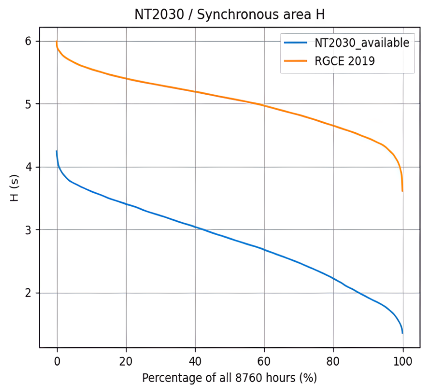
Figure 1 illustrates the expected reduction in inertia in the synchronous area of Continental Europe, comparing the equivalent inertia values H (s) recorded in 2019 (in orange) with those projected for 2030 (in blue), considering an energy transition scenario based on the policies already declared by the Member States to achieve carbon neutrality [
6,
7].
The reduction in inertia, which can even reach a third of the value recorded in 2019 [
7], is directly associated with the increasing penetration of wind and solar production, since these technologies, due to their characteristics and the way they are connected to the grid, contribute very little to the inertia of electrical systems.
Table 1 shows the inertia contribution by type of production in Continental Europe [
8].
Currently, the inertia of electrical systems is largely ensured by the kinetic energy accumulated by the rotating masses of conventional production systems, which rotate at the same electrical speed in a synchronous manner, imposed by the frequency of the grid in which they are inserted, as is the case with thermal, hydroelectric, and nuclear power plants.
2. Synchronous Inertia of Generator Sets
The inertia of rotating masses is essential to ensure the stability of the electrical grid, contributing to the safe and reliable operation of power systems. It can be understood as the ability to resist sudden changes in frequency, resulting from imbalances between production and consumption, which occur, for example, when a generator goes out of service due to a fault. The greater the inertia of a system, the greater its stability in the face of such imbalances and, therefore, the smaller the frequency deviation observed in the grid.
The synchronous inertia of an electrical machine involves quantifying the kinetic energy stored by its large rotating masses, which rotate at the same synchronous speed in the infinite capacity grid in which they are inserted. The kinetic energy stored by a body in rotational motion can be calculated from the equation:
where:
J: moment of inertia of the rotor mass (and its couplings) in kg∙m2;
w: angular velocity in rad/s;
Ec: kinetic energy stored by a body in rotational motion, in Joules.
Replacing the angular velocity
w with its relation to the frequency
w = 2πf, the equation can be simplified to:
The inertia constant of a synchronous generator,
Hi, can be defined as the ratio between the kinetic energy stored by the rotating body, that is, by the rotor mass and its couplings, and the nominal apparent power of the machine:
where:
J: moment of inertia of the rotor mass (and its couplings) in kg∙m2;
Ec: kinetic energy stored by a body in rotational motion, in Joules;
Sn: nominal apparent power of a synchronous generator i, in MVA;
Hi: inertia constant of a synchronous generator i, in seconds.
The inertia constant is quantified in seconds (s), as can be seen from the following equation:
It is also observed that different machines with the same nominal apparent power can, depending on their constructive characteristics, present different inertia values, contributing to a greater or lesser degree to frequency stability. Currently, one way to increase the inertia of rotating machines is by installing flywheels coupled to the rotor of synchronous machines. In this case, it is possible to reach inertia constant values of up to 16 s, a value about four times greater than the typical values of conventional combined cycle production units installed in Continental Europe (
Table 1). In high apparent power machines, these values can correspond to about 4000 MW∙s of accumulated kinetic energy [
9,
10].
It can thus be concluded that the rotational inertia offered by a synchronous generator is directly proportional to the kinetic energy accumulated by the rotor masses (and their couplings) in rotational motion. This energy is released immediately in the event of an imbalance in the grid, naturally attenuating the frequency variation in such a situation. At the same time, it helps to understand why the inertia (synchronous) constant of renewable energy sources, such as solar and wind, is considered zero, namely, due to the absence of rotating masses in synchronized rotational motion with the electrical grid.
3. Dynamic Equilibrium in the Operation of Synchronous Generators and Frequency Stability
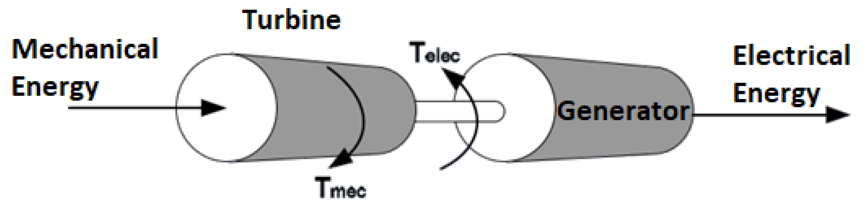
A synchronous generator coupled to a turbine can be represented as two large masses in rotational motion, with two opposing torques, as shown in
Figure 2 [
10]:
The mechanical torque developed by the turbine, Tmec, acts to increase the angular velocity w, while the electromagnetic torque, Telec, produced by the generator, acts in the opposite way, reducing that same velocity. When the torques are equal in magnitude, Tmec = Telec, the angular velocity w becomes constant, thus reflecting the dynamic stability of the turbine and generator assembly.
The mechanical torque applied by the turbine to the generator will then be:
where:
Tmec: rotational torque supplied by the turbine to the generator in N.m;
Pmec: mechanical power supplied by the turbine to the generator in W;
w: angular velocity of the machine, or rotation of the rotor shaft in rad/s;
The active electromagnetic power developed by the three-phase synchronous generator in parallel with the infinite capacitance synchronous network, where the armature resistance of the generator is neglected, as is usual in high-power machines, is obtained by the following equation:
where:
Pelec: electromagnetic active power developed by the generator in W;
Vt: phase voltage at the generator terminals in V;
E: electromotive force induced in the armature in V;
δ: angular deviation of the machine, or phase angle with respect to a synchronous reference axis;
Xs: synchronous reactance of the armature in Ω;
The stability limit in the operation of the synchronous generator is verified for a phase angle
δ of 90°, which corresponds to the maximum active power value and develops the maximum electromagnetic torque. The electromagnetic torque developed by the generator is:
As shown in
Figure 2, the electromagnetic torque has the opposite direction to the mechanical torque. In dynamic equilibrium, these torques are equal in magnitude, with the acceleration (deceleration) torque being zero, and the rotation of the generator set will be stabilized and constant.
In a stable regime, all generators in parallel with the infinite capacity synchronous network rotate at the same electrical speed, or frequency-dependent pulsation, that is, we = 2πf, in rad/s.
The angular rotation speed of each generator set is wm = 2πn, where n is the mechanical rotation of the generator in rps (revolutions per second).
The electrical speed of the synchronous network (frequency) and the mechanical rotation speed of each generator set are related by the pairs of magnetic poles
p of the generator sets, that is:
Thus, the relationship between frequency (electrical speed) and the rotation of the generating units is verified, and it is evident that changes in the rotation of the generating units have an impact on the frequency of the infinite capacity synchronous network, in which they are interconnected in parallel.
The dynamic stability of the operation of the generating units is associated with the kinetic energy accumulated in the rotating masses of the unit (turbine and generator), according to the following equations:
where:
Tmec: mechanical torque imposed by the turbine on the generator in N.m;
Telec: electromagnetic torque developed by the generator in W;
Pelec: electromagnetic power developed by the generator in W;
Pmec: mechanical power supplied by the turbine to the generator in W;
J: moment (coefficient) of inertia of the rotating masses in kg∙m2;
w: angular velocity of the machine in rad/s;
This dynamic stability can be disturbed, either by electrical reasons, such as changes in the electrical load demanded of the generator, or by mechanical reasons, such as changes in the mechanical torque developed by the turbine that drives the generator. This dynamic equilibrium, impacting the rotation of the turbine-generator assembly, is represented by the following equation:
where:
J: moment of inertia of the rotor mass (and its couplings) in kg∙m2;
: is the angular acceleration in rad/s2;
Ta: is the acceleration (deceleration) torque of the machine in N·m;
Δw represents the deviation of the angular velocity from the nominal (or synchronous) speed, in rad/s, where δ is the angular deviation of the machine, or phase angle, relative to a synchronous reference axis.
The angular acceleration of the machine will be:
The dynamic equilibrium of the turbine-generator system can also be represented by the following equation:
The acceleration power,
Pa, will be obtained using the following equation:
Knowing that the angular momentum of a body in rotational motion is:
where:
M: corresponds to the angular momentum, expressed in kg.m2/s;
J: moment of inertia of the rotor mass (and its couplings) in kg∙m2;
w: is the angular velocity in rad/s;
Since the synchronous machine rotates, under normal conditions, at synchronous speed, except when the stability limit is exceeded and the machine loses synchronism with the network, M can be considered constant. Based on this assumption, M = J can be considered.
Thus, the equation for the inertia constant of a synchronous generator,
Hi, can be obtained using the following equation:
The angular momentum
M is obtained using the following equation:
Thus, the equation that translates the dynamic equilibrium of the Turbine-Generator system’s power, considering all units in p.u. (per unit), is as follows:
Based on the above, duly justified by the equations presented, especially Equations (10)–(13), it is verified that frequency stability is strongly sensitive to the balance of active power, that is, at each instant the active power generated must equal the active power of the load plus the active losses in the transmission lines. It can be concluded that, in the face of an imbalance in the electrical load supplied by the generators, the greater the coefficient of inertia J, as well as the inertia constant of the synchronous generators H, the smaller the angular acceleration, Equations (12), (13) and (17), and, consequently, the smaller the frequency deviation in relation to the nominal or synchronism value. This is a desirable situation to maintain frequency stability during such a disturbance. It can thus be seen that high values of the inertia coefficient J and the inertia constant H contribute to attenuating the rate of frequency change (in Hz/s) during a disturbance, ensuring frequency stability and providing robustness to the electronic systems, i.e., the ability to prevent the frequency from deviating from the nominal value, with all the consequences that may result from this.
3.1. Rate of Change of Frequency
To quantify the rate at which frequency deviation manifests itself in a power system when subjected to a disturbance and to relate it to the inertia constant of each generator, the RoCoF (Rate of Change of Frequency) indicator is used, which directly reflects the system’s robustness in the face of an imbalance, and whose relationship with the synchronous machine is presented below.
From the equation of motion already presented in (10), which is developed for a synchronous machine
Hi,, the RoCoF indicator is used based on all generators interconnected in a power system. Thus, it is useful to define the system’s inertia constant
Hsys, calculated from the weighted average of all contributions:
where:
Hi: is the inertia constant of a synchronous generator i, in seconds;
Si: is the nominal apparent power of the synchronous generator i, in MVA;
Ssys: is the nominal apparent power of all interconnected groups, in MVA;
Hsys: is the inertia constant of the system, in seconds.
Presenting the moment of inertia
J, as a function of the system inertia constant
Hsys, as presented in Equation (15),
J can be substituted in the equation of motion (10) by:
Thus, Equation (10) can be presented as follows:
Given that
Pmec −
Pelec is the acceleration (deceleration) power, it can be represented by ∆
P, and rearranging the equation for the rate of change of frequency, we obtain:
The RoCoF indicator represents the frequency deviation that occurs over a given time interval, df/dt can be replaced by RoCoF, resulting in:
where:
∆P: corresponds to the power imbalance between production and consumption in MW;
Ssys: is the total installed power in the system in MVA;
f: is the nominal frequency of the system in Hz;
Hsys: is the system inertia constant in MWs/MVA, calculated from the resulting contribution of the interconnected synchronous generators;
RoCoF: is the rate of change of frequency at the moment of imbalance in Hz/s.
Analysing the expression of Equation (22), it is verified that the RoCoF indicator is inversely proportional to the system inertia constant Hsys. Thus, the greater the inertia of the system, the lower the frequency oscillation rate in the face of an imbalance that may occur in the active power of the system.
3.2. Impact of Inertia on the Rate of Change of Frequency
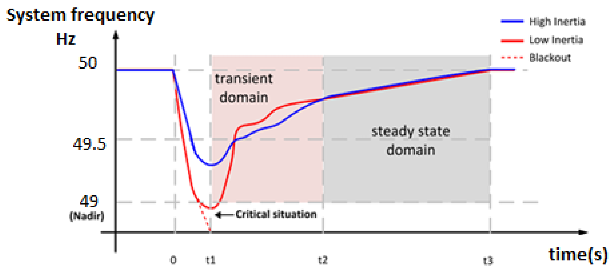
Systems with high RoCoF values, that is, with low inertia, reduce the time available for the activation of the network’s frequency regulation mechanisms, which can lead to system collapse if frequency values outside the safe and desired operating range are reached.
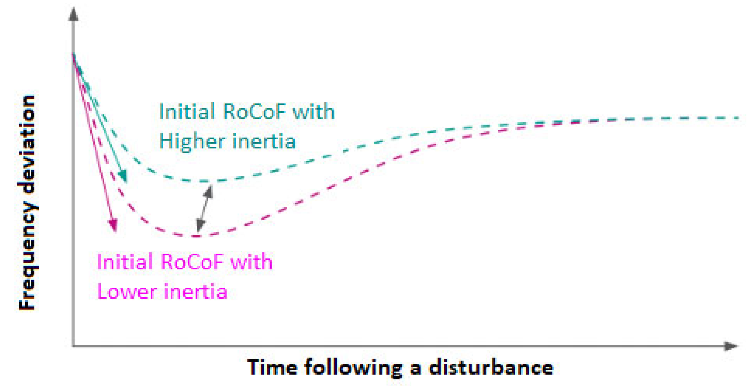
This concept is illustrated in
Figure 3, which compares the frequency deviation recorded after an imbalance between production and consumption in electrical systems with low and high inertia.
As can be seen in
Figure 3, a more pronounced RoCoF is observed for low inertia systems (in purple), resulting in minimum frequency values, usually referred to as Nadir, which can exceed the values considered to be the limit for the stability of the power systems and trigger the disconnection of the synchronous generators, with the consequent cascade collapse of the system.
In reality, the term Nadir is commonly used to refer to the minimum frequency value reached during an imbalance in the electrical grid, close to the stability limit or the activation threshold of under frequency protections.
Indeed, although generators in service on the European electricity grid must be able to operate without disconnecting from the grid within a frequency range between 47.5 and 51.5 Hz (for certain periods of time) [
13], studies show that Nadir values below 49 Hz can trigger critical situations for grid stability [
14]. Thus, Transmission Systems Operators (TSOs), in Portugal and generally in all European countries, define the Nadir value at 49 Hz as the threshold for activating load shedding as a measure to mitigate the imbalance between production and consumption.
The behaviour of frequency over time, after an imbalance between systems with low and high inertia, can be analyzed in
Figure 4. The importance of inertia is evident not only in damping the rate of change of frequency (RoCoF), but also in preventing the Nadir frequency value, corresponding to the activation thresholds of load shedding, from being reached.
As can be observed in
Figure 4, the low-inertia system, represented by the red line, in the presence of an imbalance presents a high RoCoF (steep slope), leading to a rapid exceeding of the Nadir frequency (critical situation at t ≈ t1), crossing the limits that ensure system stability. This situation can trigger the shutdown of the operating generators and, consequently, a blackout, as represented by the dashed red line.
In the high-inertia system, represented by the blue line, the RoCoF is visibly lower, and at the same instant t ≈ t1), the system frequency is still far from the Nadir value. This aspect plays a crucial role in the stability of electrical systems, as it provides a time interval between (0 ≤ t ≤ t1) that allows the TSOs to activate the frequency control mechanisms foreseen in the System Services before the critical Nadir frequency value is reached by restoring the balance between active power production and consumption.
The inertia of the SEE is therefore particularly important during this period, also known as the transient period (or transient domain), which occurs immediately after an imbalance, during which it acts as a mechanism that dampens frequency oscillations, keeping it above the Nadir value, until the TSOs can activate the aforementioned regulation mechanisms foreseen in the System Services.
4. Voltage Stability
Voltage stability is associated with the balance that must be verified in power systems between the reactive energy injected and consumed in the electrical networks. The ability of the synchronous machine to supply or absorb significant amounts of reactive energy, according to its nominal power, becomes especially useful in the voltage control of power systems, given the direct relationship between reactive power and voltage amplitude [
16,
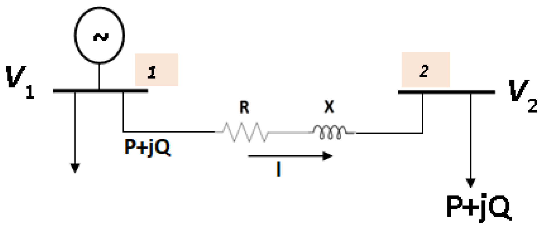
17]. Consider a system with two buses interconnected by a line, as represented in
Figure 5:
In the simplified system shown in
Figure 5, rewritten in phasor notation, it is considered that:
V1: is the voltage at bus 1, and V2 is the voltage at bus 2;
The line impedance is Z, which is represented by its resistive component R and reactive inductive component X, obtained from Z = R + jX;
I: represents the current flowing through the line between the two buses;
P corresponds to the active power and Q to the reactive power.
To mathematically establish the relationship between reactive power and voltage amplitude, we start from the voltage equation at busbar 2, expressed by [
16]:
In high and very high voltage transmission lines, it is known that
R ≪
X, and Equation (18) is simplified to:
Considering busbar 1 as the reference for the arguments, and considering, for simplification, a purely inductive line, the current
I flowing through the line is calculated by the following equation:
Substituting Equation (24) into Equation (23), we obtain:
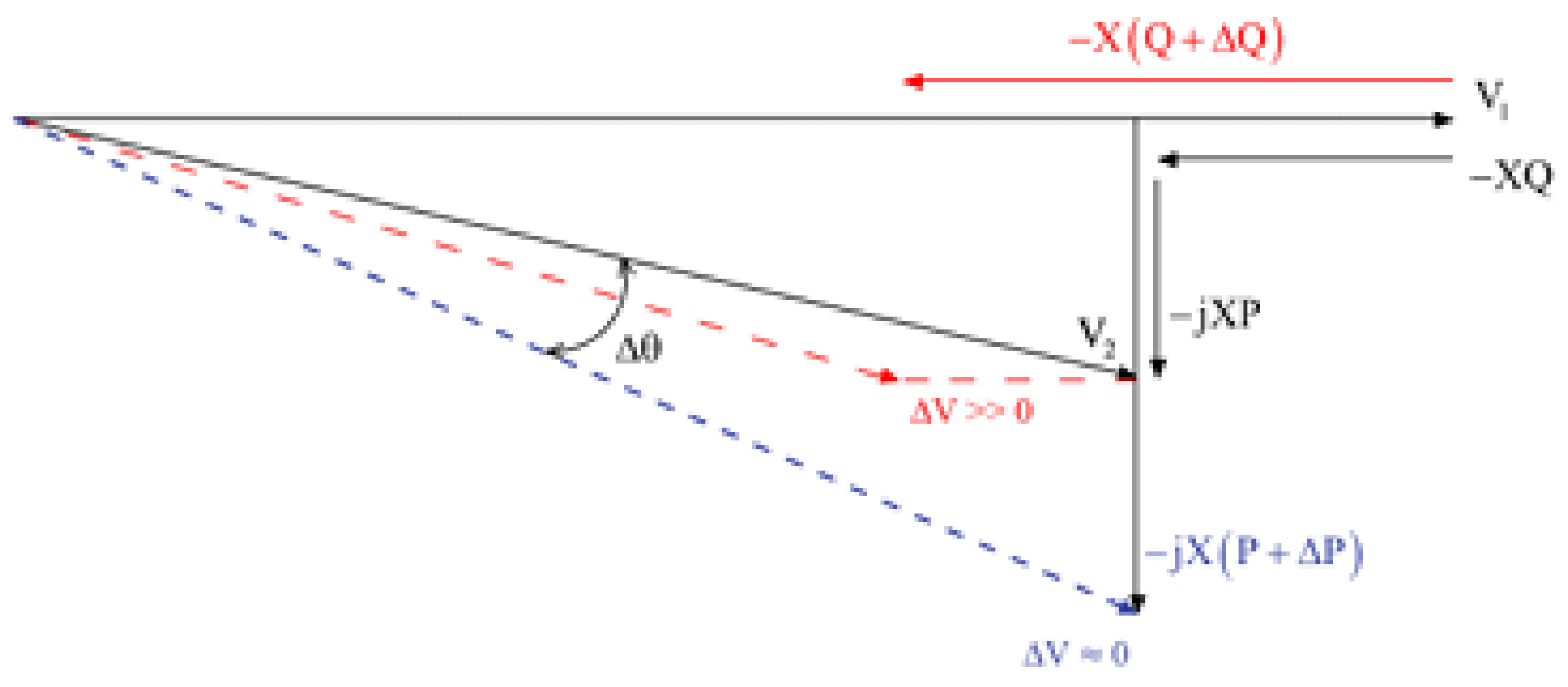
Analysing Equation (26) shows a direct relationship, inherent to all SEEs, between active power and voltage argument, and between reactive power and voltage amplitude [
16]. This conclusion becomes more evident if Equation (26) is represented in a vector diagram, as shown in
Figure 6 [
17]:
From the vector diagram shown in
Figure 6, the following can be concluded:
A variation in active power (∆P), reflected in the imaginary component (j), causes a phase shift of V2 relative to V1 but does not result in a significant variation in amplitude (∆V ≈ 0).
A variation in reactive power (∆Q) mainly affects the real component of the voltage, leading to a significant variation in the amplitude of V2 and only a small effect on the voltage argument (∆θ ≈ 0).
Unlike frequency stability control, which is centrally performed in the control centers of the power systems, voltage control can be geographically decentralized at the substation (busbar) level of the power systems. Thus, to maintain a constant amplitude of V2, variations in reactive load (∆Q) must be cancelled at busbar 2. This is achieved using capacitor banks or static synchronous compensators. Voltage fluctuations can be attenuated by manually or automatically adjusting the transformer ratios.
Synchronous generators also play a fundamental role in this aspect of voltage stability control. In reality, adjusting the magnetic excitation of the generators allows them to inject reactive power into the grids (overexcited generators) or consume reactive power from the grids to which they are connected (under-excited generators), thus contributing to the balance of reactive power and, as such, to voltage stability.
The reactive power developed by the three-phase synchronous generator in parallel with the infinite-capacity synchronous grid, where the resistance of the generator armature is neglected, as is usual in high-power machines, is obtained by the following equation:
where:
Q: reactive power developed by the generator in VAr;
Vt: phase voltage at the generator terminals in V;
E: electromotive force induced in the armature in V;
δ: angular deviation of the machine, or phase angle with respect to a synchronous reference axis;
Xs: synchronous reactance of the armature in Ω;
In general, the operation of synchronous machines is based on the following assumptions:
If δ > 0, the electromagnetic active power developed by the machine is positive, and the machine operates as a generator.
If δ < 0, the electromagnetic active power developed by the machine is negative, and the machine operates as a motor.
If in Equation (27) the term Ecosδ > Vt, the synchronous machine supplies reactive power to the grid. In this case, the machine is said to be overexcited.
If in Equation (27) the term Ecosδ < Vt, the synchronous machine receives reactive power from the grid. In this case, the machine is said to be under-excited.
The maximum active power generated (or absorbed) by the machine is verified for δ = 90°. This power angle (also called phase angle) represents the stability limit in steady-state operation of the machine.
The excitation control of the synchronous machine acts on the magnitude of the electromotive force induced in the armature,
E. This adjustment of the machine’s excitation defines the power factor regime in which the machine will operate, defining the magnitude of the reactive power that the machine will inject, or consume, from the network to which it is interconnected. This procedure decisively contributes to voltage stability in the electrical network. A situation in which the excitation control of synchronous generators also contributes to voltage stability in the electrical network is based on the fact that during off-peak hours (during the night), transmission lines are unloaded, increasing the voltage at the terminals and, as such, presenting themselves as a capacitive load for the generators. In this case, the generators are under-excited, decreasing the value of
E to a value of magnitude smaller than the voltage at the terminals,
Vt. In this case, as can be seen from Equation (27), the reactive power
Q is negative, which means that the generators are consuming reactive power from the network to which they are connected, stabilizing the network voltage at the nominal value. This possibility of controlling the excitation of the machine contributes decisively to the voltage stability in the electrical system to which it is connected [
18].
Whenever necessary, there is also the possibility of synchronous machines functioning as synchronous compensators, that is, as generators (or consumers) of reactive power, controllable through their excitation current, consuming a small percentage of active power (equivalent to losses) to remain in operation. In this case, the synchronous machine operates only in two quadrants, as it does not have a primary drive [
18].
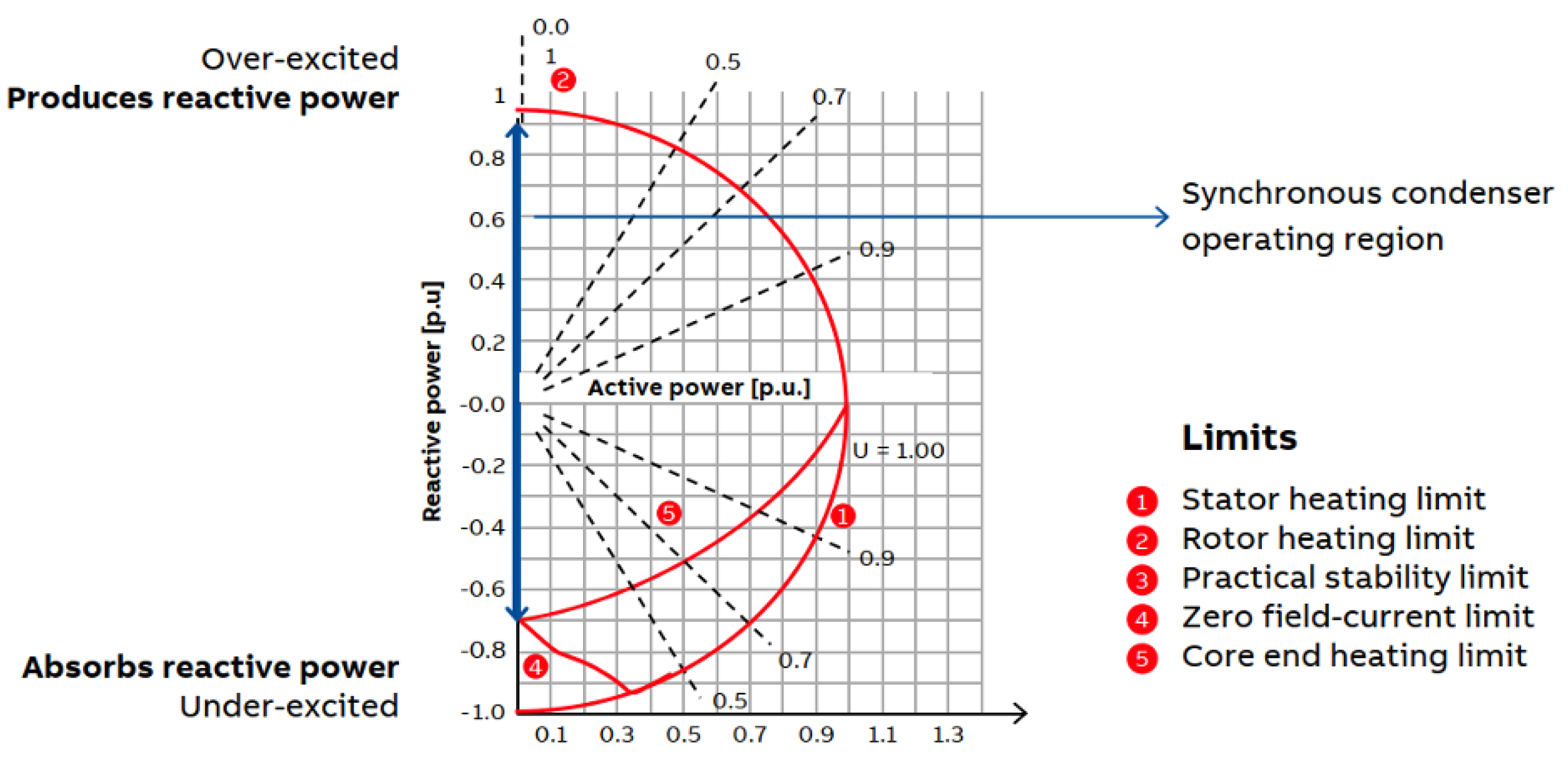
Its operation in this regime can be illustrated by the typical capacity diagram of a synchronous compensator shown in
Figure 7 [
19]. The horizontal axis represents the active power consumption component, equivalent to losses, which, for simplification, can be considered (graphically) negligible (typically between 1.0% and 2.0%). Thus, all operating points of the machine are represented along the vertical axis, as indicated by the blue line, corresponding to the supply or consumption of reactive power. Also shown in the same diagram are the curves, in red, that trace the operational limits of the machine. By crossing the red curves with the machine’s operating points represented on the vertical axis in blue, it can be observed, in reference to its power in p.u. (per unit), that:
In overexcitation, the machine supplies reactive power to the grid (machine in capacitive power factor regime), up to a value of QC = 0.90 p.u.;
In under excitation, the machine consumes reactive power from the grid (machine in inductive power factor regime) up to a value of QI = 0.70 p.u.;
The most usual situation of the synchronous compensator is with the machine overexcited, injecting reactive power into the network. In this situation, the phase angle δ is practically zero (0°), and the reactive power Q is positive, corresponding to a value of the electromotive force induced in the armature E greater than the voltage at the terminals Vt, as can be seen from Equation (27).
Another great advantage of the machine being able to function as a synchronous compensator, in addition to contributing to voltage stability as mentioned, lies in the fact that there are rotating masses hanging from the network, increasing the synchronous inertia and also contributing to the stability of the electrical system frequency, as was verified in
Section 3.
5. Solutions for Inertia Compensation and Ensuring Frequency and Voltage Stability
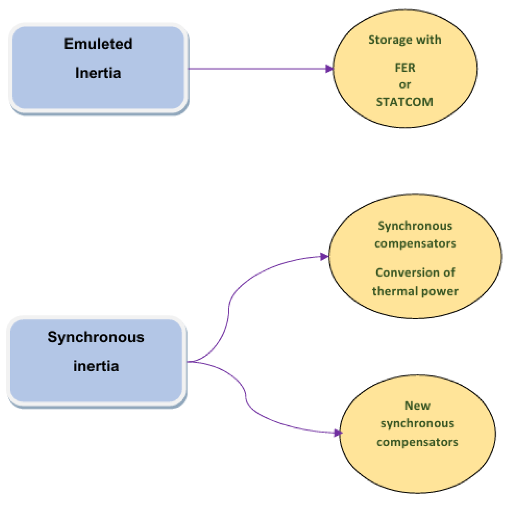
The growing and inevitable predominance of renewable energy sources (RES) in the operation of power systems necessitates the use of various technological solutions that have been explored to ensure system stability in the absence of synchronous generation, as shown in
Figure 8.
On the one hand, although emerging, inertia emulation solutions, or synthetic inertia, for example, associating Energy Storage Systems (ESS) with renewable energy sources or with STATic synchronous Compensators (STATCOM), are a solution that is already viable and technically evolved, meeting the evolution that is occurring in control systems and power electronics [
20,
21].
On the other hand, the use of synchronous compensators, a technology that has been widely developed and present in power systems for decades in reactive power compensation, with the inherent guarantee of voltage stability, also contributing to the increase in short-circuit power, offering synchronous inertia to power systems since they are rotating masses in service on the network, is also a very viable alternative.
5.1. Emulation of Inertia, or Synthetic Inertia
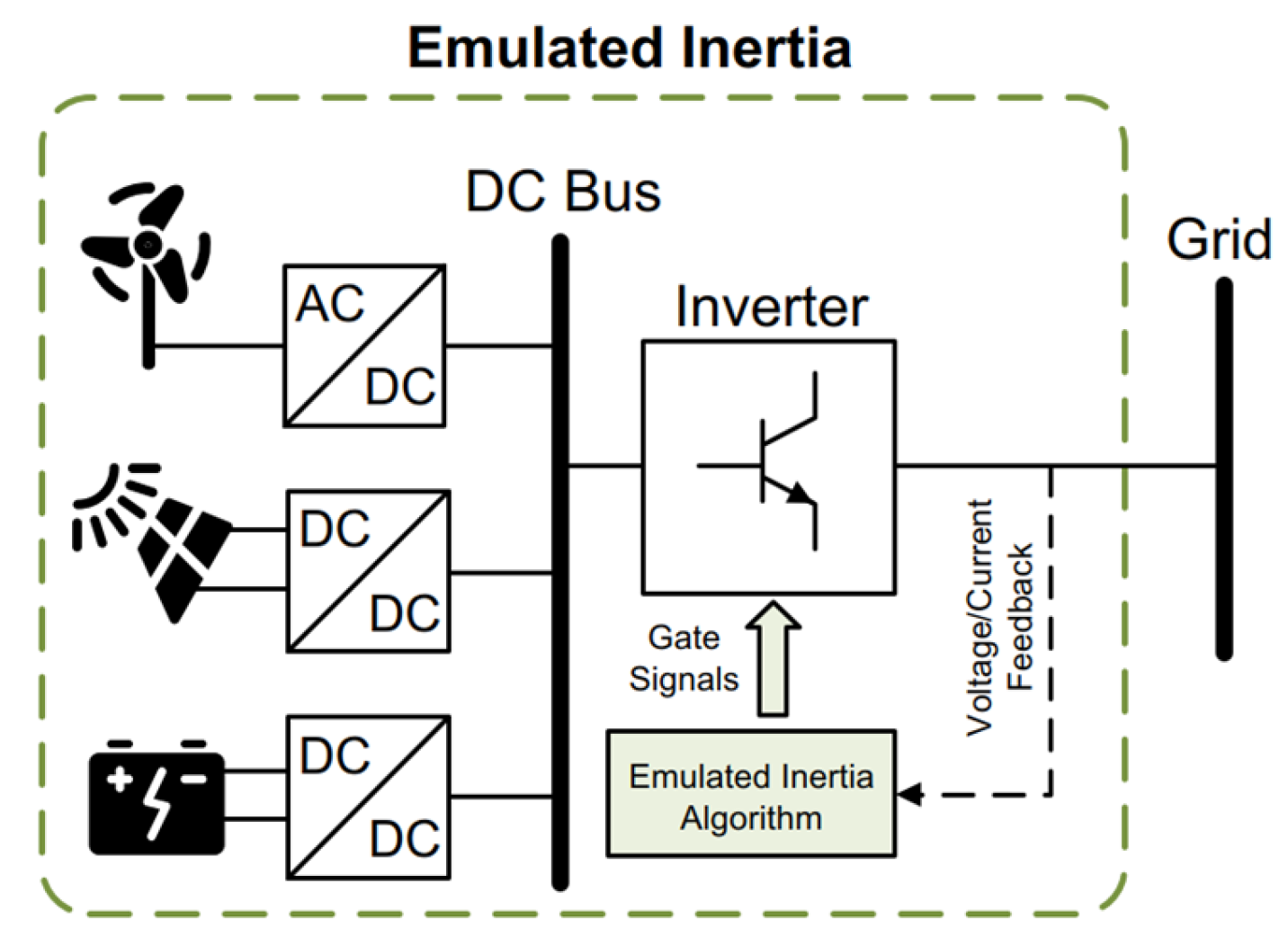
In this concept of inertia emulation, present on a small scale in power systems, power electronics converters are used, capable of ensuring active frequency and voltage regulation (grid-forming technology) and control algorithms to emulate inertia through the EVs, that is, so that they provide additional power during moments of frequency and voltage imbalance in the electrical system. This grid-forming technology refers to the ability of an energy source, such as wind, solar, or batteries, connected to the grid through electronic converters, a technology already widely developed, which allows ensuring active frequency and voltage regulation [
21,
22,
23,
24]. This concept of synthetic inertia emulation is shown in
Figure 9.
One of the main implementation difficulties generally stems from the need for renewable energy sources to operate below their nominal power (production curtailment), reducing economic benefits in energy production [
21,
22,
23,
24]. Also within the scope of the concept presented in
Figure 9, there are other inertia emulation solutions, which include the association of Energy Storage Systems (ESS) with renewable energy sources or with STATic synchronous COMpensators (STATCOM) [
20,
21,
22,
23], controlled and regulated in order to provide active power during periods of frequency imbalance in the electrical grid.
However, these technologies also have limitations related to their storage capacity and high cost [
24,
25,
26]. In the case of ESS supported by lithium-ion batteries (the most common electrochemical storage option), known as Battery Energy Storage Systems (BESS), problems related to the lifespan of these batteries still arise. Although reference values for lithium-ion batteries point to a lifespan of 20 years, studies indicate that their use in frequency regulation can reduce the lifespan to about 12 years and, when used in a peak shaving context (storing energy during periods of lower consumption and lower price for later use or sale during hours when the price of electricity is higher), decrease to about 8 years, that is, less than half the value initially estimated [
27,
28].
Thus, synthetic inertia solutions, although promising for the medium and long term, are still in an emerging phase, lacking greater technological and economic maturity before they can be implemented on a large scale as a viable alternative to synchronous inertia [
25,
26,
27,
28,
29]. Indeed, widespread adoption of the technology is not expected before 2028, and it is expected that by then a large volume of power converters (associated with the RES (Renewable Energy Sources) already under construction) will be installed without the capacity to contribute significant values of inertia [
20].
Therefore, the contribution of RES (Renewable Energy Sources) to the overall inertia of electrical systems remains somewhat limited at present.
5.2. Synchronous Inertia
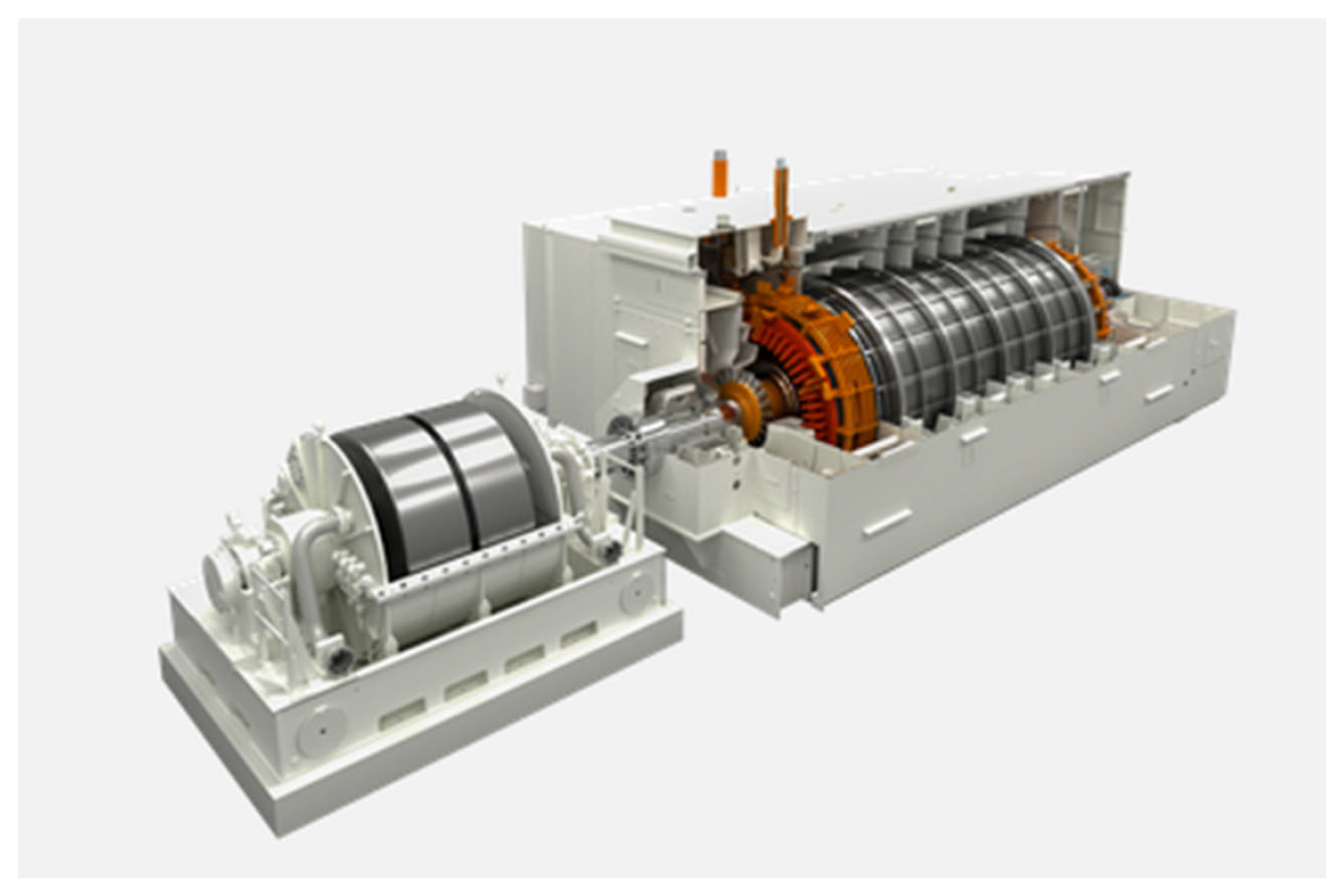
Due to their technological maturity and ability to provide intrinsic inertia, synchronous compensators are seen as one of the most promising solutions to effectively mitigate the reduction in inertia of power systems in the short to medium term, offering the robustness and stability that electrical systems need to operate reliably and safely. Their contribution to frequency stability consists of coupling a flywheel to the synchronous compensator, which rotates together with the rotor and, due to its high mass, provides a significant increase in the moment of inertia compared to the turbine-generator assembly of a conventional thermal power plant, as shown in
Figure 10.
In this context, the options are divided into two main approaches: the construction of new synchronous compensators in strategic locations or the conversion of existing conventional production units into synchronous compensators, as is the case with thermal power plants that have already been decommissioned or are in the process of being decommissioned.
However, the choice between one of the two options depends on both the technical and economic feasibility of the conversion, since not all plants are in the same technical condition and state of conservation.
5.2.1. Synchronous Inertia: Conventional Thermal Production Unit Conversion
The conversion of a conventional thermal power plant to a synchronous compensator with the addition of a flywheel consists, first, of decommissioning and decoupling the turbine (primary drive) from the synchronous machine, a quick, lower-cost, and less complex solution to implement; then a flywheel is added to the group. Coupling a mass to the rotor shaft of the synchronous compensator allows obtaining solutions with moments of inertia higher than those of the simpler solution without a flywheel, representing an additional benefit that is particularly important when it is intended to implement measures to reinforce frequency stability in power systems.
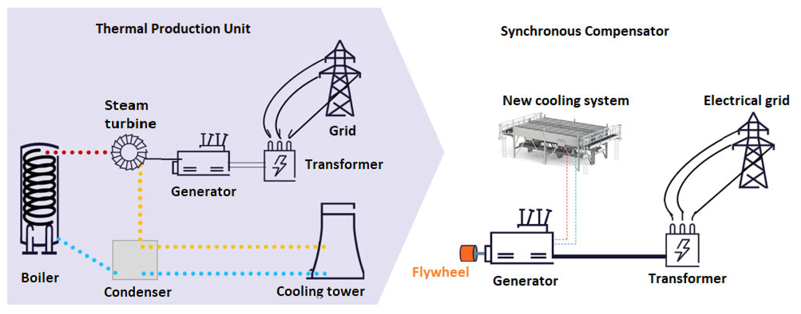
Figure 11 schematically illustrates the main modifications resulting from the conversion of a conventional coal-fired thermal power plant into a synchronous compensator, which includes the installation of the flywheel coupled to the rotor shaft of the synchronous compensator.
As shown in
Figure 11, not only is the steam turbine decoupled, but also all the equipment associated with the turbine’s thermal cycle (boiler, condenser, cooling system, and tower). Due to the reduction in cooling needs (essentially linked to the turbine’s thermal cycle), it is often necessary to install a new cooling system, sized exclusively for the new needs of the synchronous machine, and therefore more compact and efficient.
Although the example presented refers to a conventional production unit equipped with a steam turbine, the same scenario and respective modifications apply to any thermoelectric unit (with a gas, steam, or combined cycle turbine). The decoupling point between the turbine (gas or steam) and the synchronous machine usually occurs at the point of mechanical connection of the turbine rotor with the generator rotor.
After this separation, which occurs essentially for stability reasons, the synchronous machine can rotate freely and in synchronism with the grid, consuming only the active power corresponding to its losses, in contrast to a situation where the turbine was not removed, in which the mechanical losses of the turbine would be added to the losses of the synchronous machine. Within this context of the conversion process, there is also a need to re-establish the machine’s start-up process to synchronous speed, a function previously performed by the turbine through the gradual introduction of steam (or gas, depending on the type). In this context, the following solutions stand out [
21,
31]:
Mechanical starting—through the coupling of a low- or medium-voltage asynchronous motor (known as a pony motor) to the rotor shaft of the compensator. This motor, controlled by a speed variator, gradually accelerates the rotor to synchronous speed. After synchronization occurs, the power to the pony motor is removed, and it continues to rotate coupled to the synchronous compensator, also contributing to the moment of inertia. This type of starting is, as a rule, independent of the type of excitation system of the synchronous machine;
Direct electrical starting—in machines with a static excitation system (with brushes and slip rings), carried out through a static converter, also called an SFC (Startup Frequency Converter), connected to the stator of the machine. This system, based on power electronics, supplies the stator of the synchronous machine with a sinusoidal voltage of variable frequency, generating a magnetic field in the stator. This field interacts with the rotor’s magnetic field (generated by the excitation current), progressively accelerating it to about 5% above synchronous speed. At this point, the SFC is deactivated, allowing the compensator to rotate freely. A natural deceleration process then begins, due to the rotor’s inertia. It is precisely during this deceleration ramp that synchronization occurs, as soon as the speed (i.e., frequency), voltage amplitude, and phase angle are within ranges sufficiently close to the network values;
Indirect electric starting—in machines with a brushless excitation system, performed using an SFC (Startup Frequency Converter) and an auxiliary hydraulic motor. In the first phase, the hydraulic motor accelerates the rotor from a resting state (0 rpm) to approximately 300 rpm (or 10% of the nominal value), a speed at which the magnetic field generated by the brushless exciter is already strong enough to interact with the field created in the stator through the SFC, and the hydraulic motor is taken out of service. Similar to the previous example, the synchronous machine is then accelerated to a speed higher than the synchronous speed, at which point the SFC is also deactivated, followed by the same deceleration and synchronization process.
The choice between one of the options, especially between the pony motor and the SFC (Startup Frequency Converter), depends not only on the characteristics of the synchronous machine existing in the plant but also on technical and economic aspects that are evaluated within the scope of the conversion.
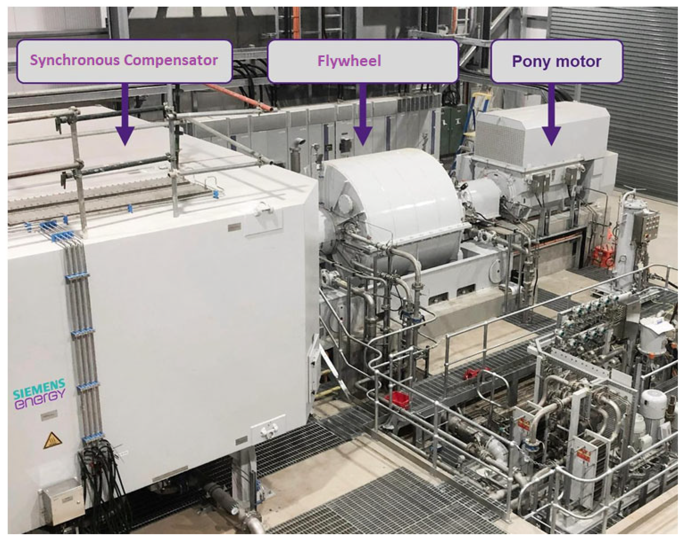
Figure 11 shows a real application of this type of solution, associated with a mechanical starting system, through the coupling of the assembly to an asynchronous motor.
As can be seen in
Figure 12, the flywheel and the pony motor are coupled to the shaft of the synchronous compensator (rotor), with the motor positioned at the end of the rotor shaft. This configuration allows for primary drive and acceleration of the entire equipment assembly during the starting and synchronization process of the synchronous compensator with the electrical network.
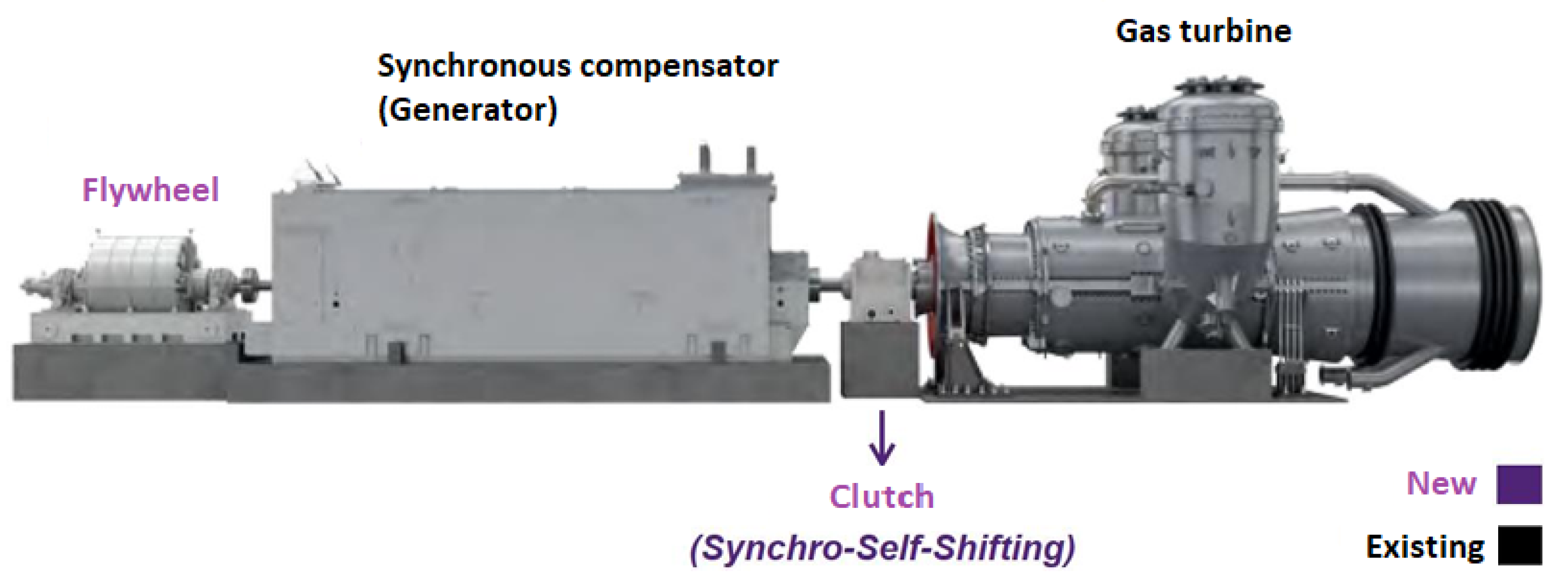
An alternative synchronous compensation solution consists of converting a thermoelectric production unit into a dual-operation synchronous compensator, that is, a system capable of switching between conventional energy production mode and synchronous compensator mode, by means of a clutch installed between the synchronous machine and the turbine (gas or steam) as shown in
Figure 13 for a gas turbine.
In this solution, the entire thermal cycle is maintained, however, a special application clutch designated Synchro-Self Shifting [
30,
33] (Siemens Energy, Synchronous Condenser, Germany) is installed that allows the turbine to be instantly decoupled from the synchronous machine and put into operation as a synchronous compensator. The same operation can be done in reverse, that is, to operate a switching from synchronous compensator mode to energy production mode, achieving this switching in about 30 min [
33]. With this type of solution, the power plant gains an additional source of revenue and can operate flexibly in two modes: electricity production and the provision of System Services, switching between operating modes according to the needs of the power supply and market attractiveness.
Figure 13.
Conversion of a gas turbine thermal power generation unit into a double-operation synchronous compensator. Figure obtained in [
34].
Figure 13.
Conversion of a gas turbine thermal power generation unit into a double-operation synchronous compensator. Figure obtained in [
34].
Regarding the start-up and synchronization process with the grid while maintaining the entire thermal cycle associated with conventional production, the start-up follows the usual procedure for a gas-fired power plant: the rotor winding is excited, and the SFC (Startup Frequency Converter) system is used to gradually accelerate the turbine-generator assembly. From a certain point, the injection and combustion of gas in the turbine chamber make it self-sustaining, allowing the SFC to be deactivated and the rotor speed to gradually increase to nominal speed, at which point synchronization with the grid is established.
5.2.2. Synchronous Inertia: Building New Synchronous Compensators
The construction of new synchronous compensators from scratch, compared to the conversion solutions presented previously, does not present differences in concept or application, although it may involve a greater investment. However, the new equipment benefits from the technological advances achieved in the meantime, in contrast to the synchronous machines installed several years ago, allowing the use of more efficient units than those reused in the context of conversion. In addition, they can be sized to meet the specific needs of the power system where they will be installed. For example, in a new design, the machine can be designed to have a synchronous reactance as low as technically possible, maximizing its contribution to the increase in short-circuit power, which is typically achieved by using cylindrical rotors. Alternatively, it can be designed with a high rotor mass if the inertia requirements are considerable, a characteristic that is traditionally more easily achieved by using salient pole rotors [
10].
It is common to find cylindrical rotor machines in thermal power plants, as their use is considered more efficient than that of salient poles in high-speed applications, such as in gas turbine-coupled power generation, providing a high contribution to increasing short-circuit power and consequent stability of the electrical power system.
5.2.3. Synchronous Inertia: Hybrid Solutions
Hybrid solutions for synchronous compensation and synthetic inertia emulation arise from the strategic combination of different FACTS technologies, maximizing the advantages of each. In this context, there are fundamentally two solutions [
8]:
Association of synchronous compensators with Energy Storage Systems (ESS): In addition to the conventional operation of synchronous compensators, this combination provides the system with the ability to absorb or supply active power in situations of imbalance between production and consumption, contributing to the re-establishment of the system’s frequency balance immediately after the inertial response of the synchronous compensator;
Association of synchronous compensators with STATic synchronous COMpensators (STATCOM): this approach combines the contributions of synchronous compensators with the advantages of static compensators, which, although not capable of contributing synchronous inertia or increasing short-circuit power, offer a faster response to voltage variations or disturbances, playing an important role in voltage control.
From a technological standpoint, the synchronous compensators used in hybrid solutions do not differ from those employed in the individual solutions presented above. The distinction of a hybrid solution lies solely in the integration of the synchronous compensator with other FACTS technologies (Flexible Alternating Current Transmission Systems), whose joint operation is coordinated by a common control system with the aim of optimizing the performance of both systems, thus obtaining more efficient operation in situations and locations where stabilization of the electrical grid operation is sought in all fundamental aspects inherent to the safe operation of power systems: frequency, short-circuit power increase, and voltage control.
Summary of the current situation regarding the contribution of different technologies to the implementation of measures for the stability of electrical power systems:
Synchronous compensator: contributes high inertia, allows voltage stability, although somewhat limited, high short-circuit power, maturity, and long service life;
Static compensator (STATCOM or SVC): does not contribute inertia, high voltage control, zero short-circuit power, technological maturity, and long service life;
Synthetic inertia (FER with grid-forming): limited inertia contribution, high voltage control, zero short-circuit power, reduced maturity, and still limited service life;
Energy Storage Systems (ESS): limited inertia contribution, high voltage control, zero short-circuit power, reduced maturity, reduced service life.
6. Conclusions
The carbon neutrality targets set by the European Union and several countries around the world have driven an energy transition, characterized by the gradual replacement of synchronous thermal generation, based on fossil fuels, with Renewable Energy Sources (RES), such as wind and solar. This has a significant impact on the level of inertia of production systems, impacting the operational security of electrical grids, frequency, and voltage stability.
The inertia of power systems is largely ensured by the kinetic energy stored in the large rotating masses of conventional production systems, rotating machines that rotate synchronously with the grid, as is the case with generators in thermal, hydroelectric, and nuclear power plants. However, in line with the objectives of the energy transition, thermal generation is being progressively phased out and replaced by Renewable Energy Sources (RES), such as wind and solar. Despite technological advancements, these still do not contribute to the inertia of power systems in a way comparable to traditional synchronous generators.
In response to the challenges posed by the energy transition, several technological solutions are being explored to ensure the stability of systems in the absence of synchronous generation, including inertia emulation or synthetic inertia solutions. These solutions, while promising for the medium and long term, are still in an emerging phase, requiring greater technological and economic maturity before they can be implemented on a large scale as a viable alternative to synchronous inertia.
In this context, synchronous compensators, a technology already widely consolidated and present in power systems for several decades in reactive power compensation, are identified as a solution that could effectively assume the role that has been played by conventional thermoelectric production, contributing to mitigating the reduction of inertia in the short and medium term. These, in addition to their intrinsic nature of contributing rotational inertia, also offer versatility in supporting other system services, such as voltage control and short-circuit power reinforcement. Among the synchronous compensation solutions, two main approaches stand out: the construction of new synchronous compensators or the conversion of existing thermal power plants into synchronous compensators.
In some of these initiatives, the conversion of existing thermal power plants into synchronous compensators was preferred over the construction of a new synchronous compensator from scratch, either for cost optimization or for speed of implementation.
In the case of converting a thermal power generation unit into a synchronous compensator, the original rotor of the synchronous machine is reused, and, therefore, the constructive solution adopted remains the same as that for which the machine was initially designed. In these cases, about two-thirds of the moment of inertia results from the rotating masses of the gas (and/or steam) turbines, which become decoupled during conversion. Thus, it is common practice, within the context of conversion, to use a flywheel to restore inertia levels similar to the original ones. Therefore, a technical and economic evaluation of the advantages and disadvantages between converting thermoelectric units and building new synchronous compensators becomes fundamental.
Summary of different technologies for the implementation of measures for the stability of electrical power systems is presented at final of
Section 5.
This article aimed not only to contextualize the problem of safety in the operation of electrical networks subject to high penetration of renewable energy sources, mathematically justifying how the inertia levels of generators are crucial for frequency stability, but also to provide a clear view of the challenges and opportunities posed by the inevitable energy transition and its relationship with the stability and safety in the operation of current electrical power systems.