Proceeding Paper

Aerial Firefighting Fleet for Wildfire Suppression: A System of Systems Approach †
by
Auraluck Pichitkul
1,*,
Kaung Sett Toe
1,
Kyaw Zaw Hlyan
1,
Soe Yu Waddy
1,
Aung Hein Kyaw
1,
Nikolaos Kalliatakis
2,
Nabih Naeem
2 and
Prajwal Shiva Prakasha
2
1
School of Mechanical Engineering, Suranaree University of Technology, Muang Nakhon Ratchasima, Nakhon Ratchasima 30000, Thailand
2
Institute of System Architectures in Aeronautics, German Aerospace Center (DLR), 21129 Hamburg, Germany
*
Author to whom correspondence should be addressed.
Presented at the 15th EASN International Conference, Madrid, Spain, 14–17 October 2025.
Eng. Proc. 2026, 133(1), 65; https://doi.org/10.3390/engproc2026133065
Published: 5 May 2026

Abstract

This study documents the design, development, and evaluation of a purpose-built aerial firefighting fleet optimized for diverse wildfire suppression environments as part of the COLOSSUS project’s X-Challenge. The multidisciplinary effort encompassed aerodynamic design, propulsion system, systems integration, cost estimation, simulation, design of experiments, and fleet optimization. Key technical advancements include a conceptual hybrid electric Vertical Takeoff and Landing (eVTOL) aircraft design, and the integration of a series hybrid propulsion model into the System of Systems Inverse Design (SoSID) simulation toolkit, in which evaluation takes place at fleet level. Simulation results indicate that the proposed aircraft achieves competitive or superior effectiveness across all test scenarios, with the series hybrid configuration offering notable endurance and tactical adaptability.

1. Introduction

This work was part of a six-month international student competition, the COLOSSUS Project’s X-Challenge. As part of the X-Challenge, teams were tasked with developing innovative aircraft designs and expanding the COLOSSUS framework with new System of Systems (SoS) insights and features. Therefore, the method, analysis and use cases presented in this work are derived from those provided by the X-Challenge’s objectives, constraints and tools. The details of the three scenarios referred to in this analysis (Salamis—Greece, Pyrenees—France, and Pacific Palisades—United States) and further information on the challenge can be found in [1].
As part of the COLOSSUS X-Challenge [1], our job is to create a new aircraft that will help fight wildfires in the future, while also coming up with creative ways to use our aircraft in conjunction with new solutions.
Aircraft performance in such missions depends on aerodynamic efficiency, propulsion capability, payload capacity, and operational flexibility, as well as life-cycle cost. This study presents the complete design and evaluation of an aerial firefighting aircraft optimized for varied environments. The process covered aerodynamic configuration, structural design, propulsion system selection, and systems integration. Multiple configurations were evaluated against mission requirements, payload–range constraints, scooping efficiency, and maneuverability in challenging terrain.
Economic considerations were integral to the design process. Acquisition and operating costs, including fuel, maintenance, and crew, were estimated to ensure the aircraft is viable for fleet deployment by firefighting agencies. Trade-off analyses balanced performance benefits against cost impacts, with the selected configuration delivering high effectiveness without prohibitive expense.
Key technical developments also include the integration of a series hybrid propulsion model for the SoSID simulation toolkit, enabling precise modeling of generator–battery–motor interactions.

2. Aircraft Design and Development

2.1. Mission Requirements

The mission requirements of our proposed firefighting seaplane are shaped by the operational goals and constraints of the COLOSSUS X-Challenge. Our approach incorporates data from historical seaplane performance, modern hybrid propulsion trends, and the challenge’s operational requirements for 2035. The mission requirements were set to ensure a feasible and competitive target of payload and range while maintaining the performance of existing firefighting aircraft. A payload-range analysis was carried out to determine the aircraft’s payload and range, which was subsequently compared to existing firefighting aircraft of similar weight class. From these aircraft, the Fire Boss [2] stands out as the most relevant benchmark in terms of mission type and size class, and our payload and range is chosen around it. All other performance targets are based on the mission’s needs. In addition, the design is constrained by specific challenge requirements, such as Maximum Takeoff Mass (MTOM), fleet-level cost, and entry into service by 2035 [3]. Table 1 summarizes the key parameters and targets for our aircraft design.

2.2. Aircraft Configuration Selection

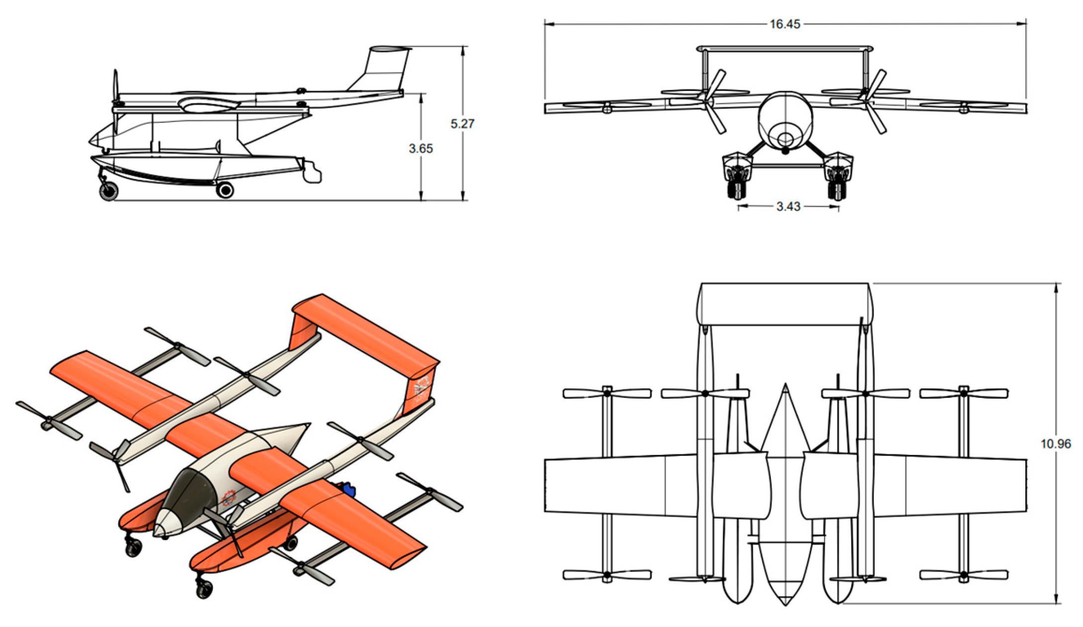
The chosen configuration for the COLOSSUS-X challenge is a lightweight amphibious seaplane with an MTOM of 6328 kg. It adopts a twin-float, high-wing, boom-mounted tail design and has Vertical Takeoff and Landing (VTOL) capability using hybrid-electric propulsion. The seaplane dimensions and data obtained by calculations and optimization in Open Vehicle Sketch Pad (OpenVSP) version 3.42.3 and Autodesk Fusion360 (build 2604.0.316) are shown in Figure 1 and Table A1.
During VTOL mode, six vertical electric rotors enable vertical lift. In the Short Takeoff and Landing (STOL) mode, the aircraft features a high-lift wing with flap systems. The power-to-weight ratio and wing loading have been optimized in the constraint analysis to allow for short takeoff from rivers and lakes when VTOL is unnecessary, thus extending mission range. The dual-mode capability enables crews to select the most efficient takeoff method based on environmental and tactical conditions.
The series hybrid propulsion system is chosen as it offers superior range, strong fuel efficiency, and balanced infrastructure and environmental performance. For the wing, it is positioned as a high wing because it can keep engines, propellers, and lifting surfaces high above water spray during scooping or taxiing. Moreover, by placing the wing high on the fuselage, float integration is simplified. The twin-boom-mounted tail configuration was chosen over a conventional single-fuselage tail for Spray Clearance. The booms act as both tail supports and structural tie-ins for VTOL mounts.
The aircraft’s primary cruise propulsion is provided by two tractor propellers mounted on booms beside the fuselage, just forward of the wing leading edge. A nose-mounted configuration is avoided as it interferes with cockpit visibility and sensor placement. Moreover, pusher propellers behind the wing can suffer from disturbed airflow, reducing propulsive efficiency, and increasing vibration [4]. They also risk water spray ingestion during scooping. Therefore, a choice is made to mount forward cruise propellers beside the fuselage as it minimizes yawing moments if one motor fails, reduces induced drag compared to wingtip mounting and supports efficient integration of the series hybrid electric powertrain.

3. Aircraft Design

3.1. Initial Sizing

3.1.1. Initial Mass Estimate

To perform the mass estimation, the mass of the seaplane is broken down into a crew and payload mass of 2578 kg and the fuel mass fractions, estimated using the statistical mass equations. The takeoff mass can then be estimated based on the equation from Raymer [5]. We set the fuel reserves required for our seaplane as 30 min reserve fuel at normal cruising speed with 100 km reserve fuel for diversion. According to our mission requirements, we determine the fuel fractions of taxi, takeoff, climb, and landing from historical data and a 1300 km range using the Breguet range equation [5]. Moreover, an additional reserve fuel fraction is calculated for our seaplane. The empty weight of the seaplane is assumed to be 45% of maximum takeoff mass. From the initial mass estimation, the takeoff mass for the design mission was calculated to be 6328 kg.

3.1.2. Critical Performance Parameters Selection

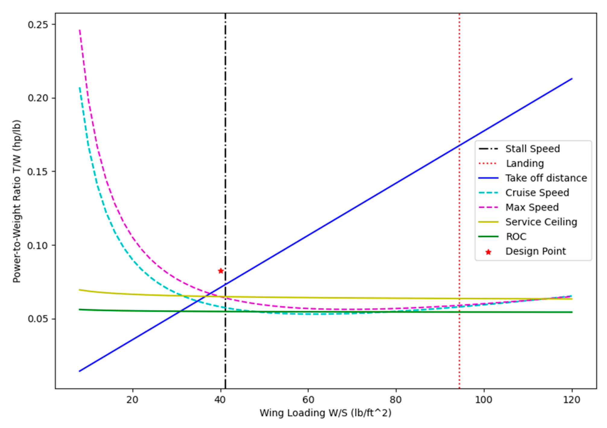
After deciding upon the design requirement, the next steps to be estimated are the critical parameters, i.e., the values of the wing loading W/S and the power-to-weight ratio P/W. These parameters are sized based on the required aircraft flight performance through constraint analysis. Constraint equations from the General Aviation Textbook [6] are used to determine the design space. To create the design space within the constraint plots, inputs for all equations are taken from similarity, are assumed, or are taken from the reference textbooks and historical data.
The constraint diagram is shown in Figure 2, and the design point is chosen to lie in the right and bottom location of the design space. The right location is desired because a higher wing loading would lead to a smaller wing area, which minimizes weight and cost. The bottom location is desired because a lower power-to-weight ratio would mean that a less powerful engine could be used, which generally reduces cost. The design point, as indicated by a red star, specifies a power-to-weight ratio of 0.0825 hp/lb and a wing loading of 40 lb/ft2. With the estimated takeoff mass, our seaplane will require a minimum wing size of 32.4 m2 and a minimum power of 847 kW. However, it should be noted that this power selection is only for the STOL mode; the VTOL mode is not included.

3.2. Wing Planform Selection

3.2.1. Airfoil Selection

The selection of airfoil is important because it has a significant impact on the aircraft’s performance throughout its flight regime. The aircraft will spend a considerable amount of time on cruises. Therefore, an airfoil which is ideal for cruise conditions was selected. The NACA 23018 airfoil was selected as the primary wing section for our seaplane due to its combination of high lift capability, gentle stall behavior, and structural depth, which are critical for amphibious firefighting missions.

3.2.2. Wing Parameters Selection

The wing planform is carefully selected based on aerodynamic theories, historical aircraft data, and calculation results. The goal was to design an efficient wing suitable for a low-speed seaplane, ensuring high maneuverability and the STOL abilities required for wildfire fighting. The design parameters are chosen based on Anderson’s book [7]. Our seaplane uses a single wing (monoplane configuration), which offers the best combination of structural simplicity, aerodynamic efficiency, and ease of manufacturing. A 2° low sweep maintains high low-speed lift efficiency, essential for short takeoff from water and precise low-speed handling in wildfire suppression missions. A taper ratio of 0.75 reduces induced drag while preserving a large enough tip chord for effective low-speed aileron control. The −2° anhedral reduces excessive roll stability from the high-wing configuration. This is critical for precise maneuvering in low-level wildfire suppression and during scooping approaches.

3.3. Tail Design

For our seaplane, a boom-mounted H-tail configuration connected by a full-span horizontal stabilizer is mounted on structural booms extending aft from the wing. The boom-mounted design positions the entire tail unit high and aft, well clear of the spray path during takeoff, scooping, and landing. Moreover, the widely spaced vertical stabilizers offer increased yaw stability and control authority. For both stabilizers, symmetric NACA 0012 airfoil was selected. These airfoils were chosen based on their suitability for tail surfaces that require control in both positive and negative angles of attack. The use of symmetric airfoils in both tails avoids the need for built-in aerodynamic twists and allows for easier control surface integration without affecting the zero-lift angle.

3.4. Mass Breakdown and Center of Gravity Calculation

The calculation of an aircraft’s mass and Center Of Gravity (COG) is fundamental to ensuring safe operation and performance. We use statistical equations from Raymer [5] to determine the mass of each component and combine them to obtain the empty weight and total weight of the aircraft. This information is used to determine the aircraft’s center of gravity, which must be within acceptable limits to ensure safe and stable flight. The calculation can be seen in Table A2.

4. Cost Analysis

4.1. Acquisition Cost Estimation

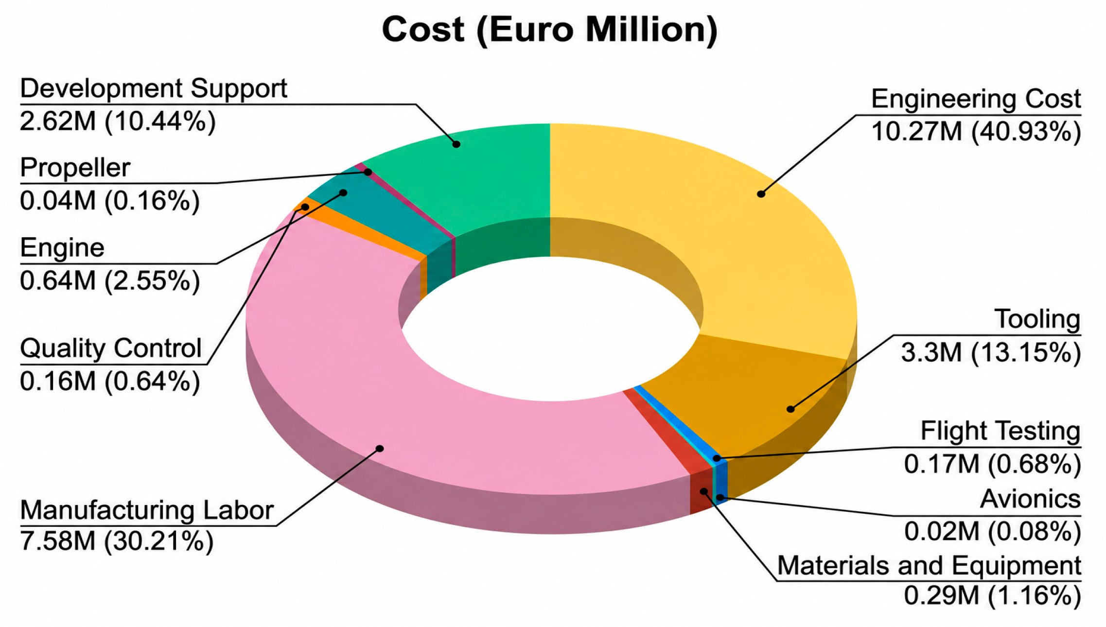
The acquisition cost of the SUT Ember AeroTech seaplane was estimated to use a parametric cost-modeling approach covering engineering, tooling, flight testing, manufacturing labor, materials and equipment, quality control, engine, propeller, avionics and development support. Based on these inputs and the cost relationships from [6], the initial unit acquisition cost is €25.09 million, as shown in Figure A1 in the Appendix B.
All cost elements were adjusted to the target year 2035 using a normalized Consumer Price Index (CPI) multiplier. Assuming an average European inflation rate of 2% per year, the CPI increases from 1.0 in 2012 to 1.577 in 2035, and this factor was applied uniformly to convert baseline values into 2035 euros [8].

4.2. Quantity Discount Factor (QDF)

A learning curve rate of 85%, representative of aerospace production, was applied to account for manufacturing efficiency gains across a six-aircraft fleet. Cost reductions are driven by cumulative production rather than elapsed time and are therefore realized progressively throughout the fleet’s serial production. Using Gudmundsson’s QDF formulation [6], the average cost per unit decreases from €25.09 million to €16.49 million, resulting in a total acquisition cost of €98.92 million.

4.3. Operational Cost Estimation

Operational costs were divided into Direct Operating Costs (DOC), including fuel/energy consumption, maintenance, and depreciation, and Indirect Operating Costs (IOC), estimated as 25% of DOC following common practice for utility-class aircraft [9]. Only the optimal performance scenario for each region is summarized in Table 2.

5. System of Systems Inverse Design (SoSID) Toolkit

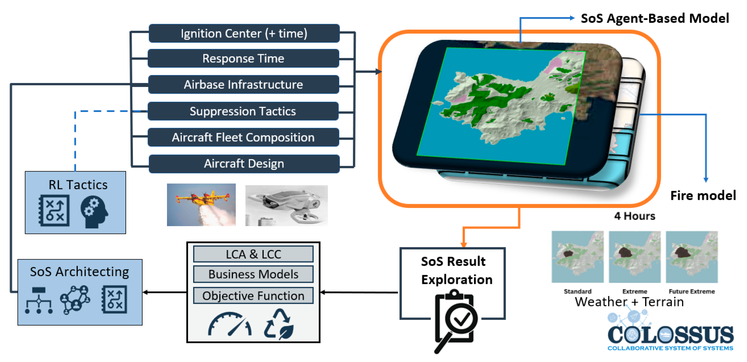
The above aircraft design and configuration was then simulated and evaluated within the SoSID toolkit. Wildfire fighting presents a complex SoS challenge, as multiple different systems work in collaboration against the wildfire. The wildfire itself is often unpredictable due to its sensitivity to the elevation profile, vegetation, and atmospheric conditions. The SoSID toolkit’s Aerial Wildfire Simulation use case, as showcased in Figure A2, models the wildfire using a cellular automata-based fire model, and couples it with the agent-based model of the firefighting systems, where its composition and tactics can be explored [10].

Development of Series Hybrid Propulsion in the Toolkit

As per the original SoSID toolkit, only conventional, electric, and parallel hybrid propulsion classes were present. To enable the simulation of aircraft employing a series hybrid propulsion architecture, a new propulsion class had to be implemented and integrated into the existing simulation framework. This class extends the modular propulsion architecture of the toolkit by supporting energy flows and power management unique to series hybrid systems.
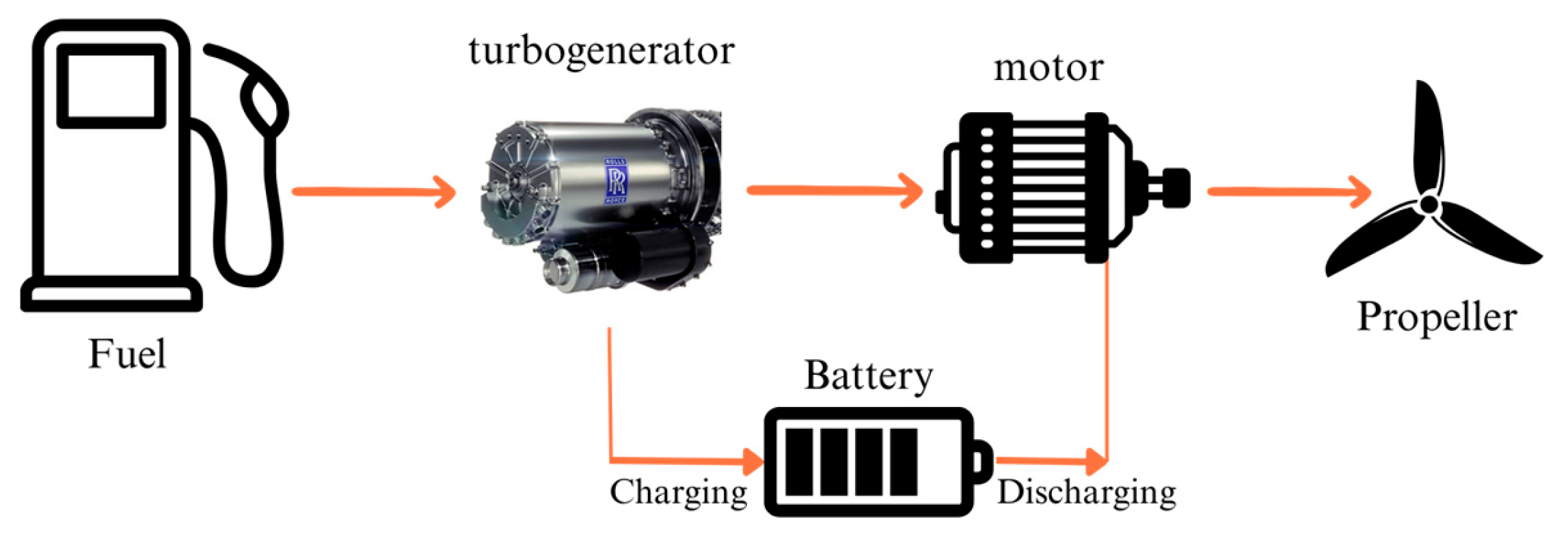
The fuel consumption rate is computed by multiplying the power demand of different flight modes by the estimated Brake Specific Fuel Consumption (BSFC) of the generator. As shown in Figure A3, the motors receive power directly from the turbogenerator. When motors require more power than the generator can supply, they draw it from the battery, which has a 1200 kW maximum output capacity. In order to prevent overcharging, the battery’s maximum allowable State of Charge (SoC) is 0.9, meaning it can be charged to 90% of its capacity. A minimum reserve of 15% SoC is maintained, at which the aircraft would return to the base for plug-in charging.
In the simulation toolkit, this extended class was validated using the team’s custom aircraft configuration. It can generalize to other series hybrid aircraft designs in future applications, enabling broader SoS representations and design space explorations.

6. Fleet Optimization by SoSID Simulations

6.1. Multi-Objective Optimization

The objective function is a combination of all the essential outputs from the SoSID toolkit. Measure of Effectiveness (MoE) [1] is applied to systematically evaluate the fleet performance.

6.2. Design of Experiments (DoE)

Each DoE analysis conducted for the Salamis, Pyrenees, and Palisades regions evaluates how the MoE changes with variations in suppression tactics and the number of deployed aircraft (fleet size). The objective is to determine the combination of suppression tactics and fleet size that delivers the highest MoE, providing insight into optimal resource allocation for wildfire suppression under differing geographic and operational conditions.
A Python module was developed in the SoSID toolkit by the SUT team to automate the creation of fleet composition and suppression tactics configuration files for the DoE. The script reads structured scenario setups from an Excel worksheet and converts them into JSON format compliant with the toolkit’s input requirements. This functionality enables DoE workflows by allowing multiple scenarios to be generated in batch, significantly reducing the time, effort, and error risk compared to manual JSON file creation.

6.2.1. Salamis, Greece

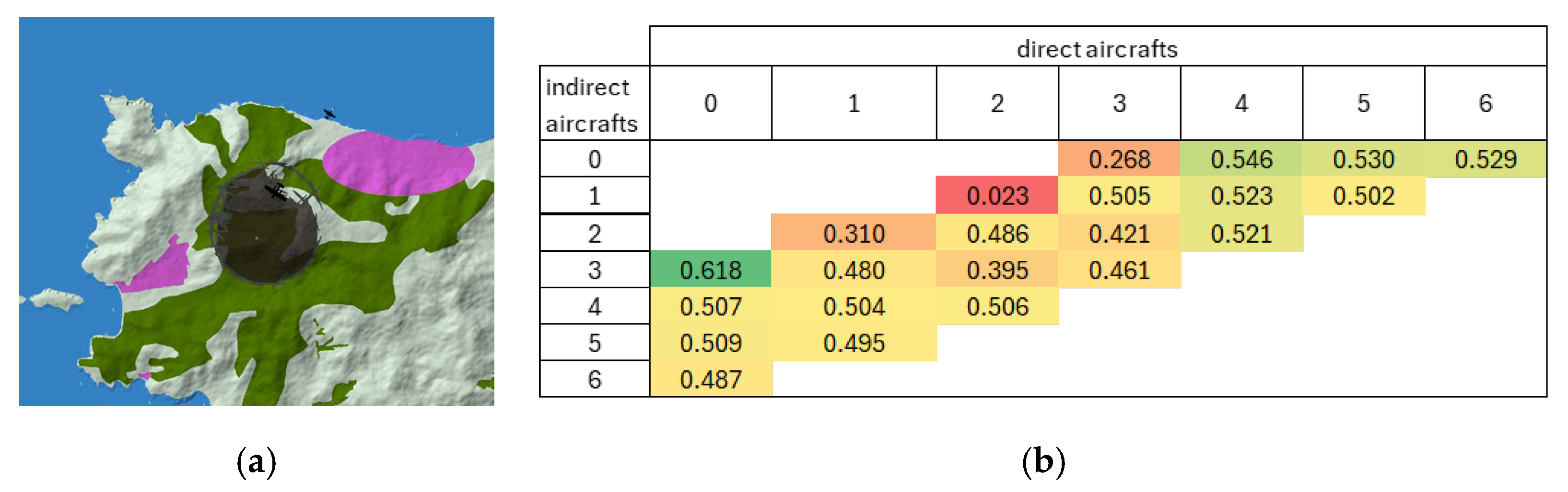
For Salamis, given the 2 h aircraft response time, fires are already large and difficult to control upon arrival, making adopting an indirect attack the most suitable primary tactic [11]. The highest MoE (0.618) occurred in a scenario, where all three aircraft performed indirect attacks as shown in Figure 3. In small fleets, indirect attacks consistently outperformed mixed or direct-only tactics. For larger fleets, using all aircraft in a direct attack also achieved high MoE, but split-tactics groups reduced effectiveness. The heat map confirms that optimal results are achieved when all aircraft operate according to a single, coordinated tactic.
The GUI of Figure 3a distinguishes environmental features by color: blue represents water sources for scooping, green indicates vegetation, and pink highlights residential areas. The black regions signify areas where the fire has been successfully contained or extinguished. The color-coding defined here is consistent across all GUI representations in this study.

6.2.2. Palisades, California

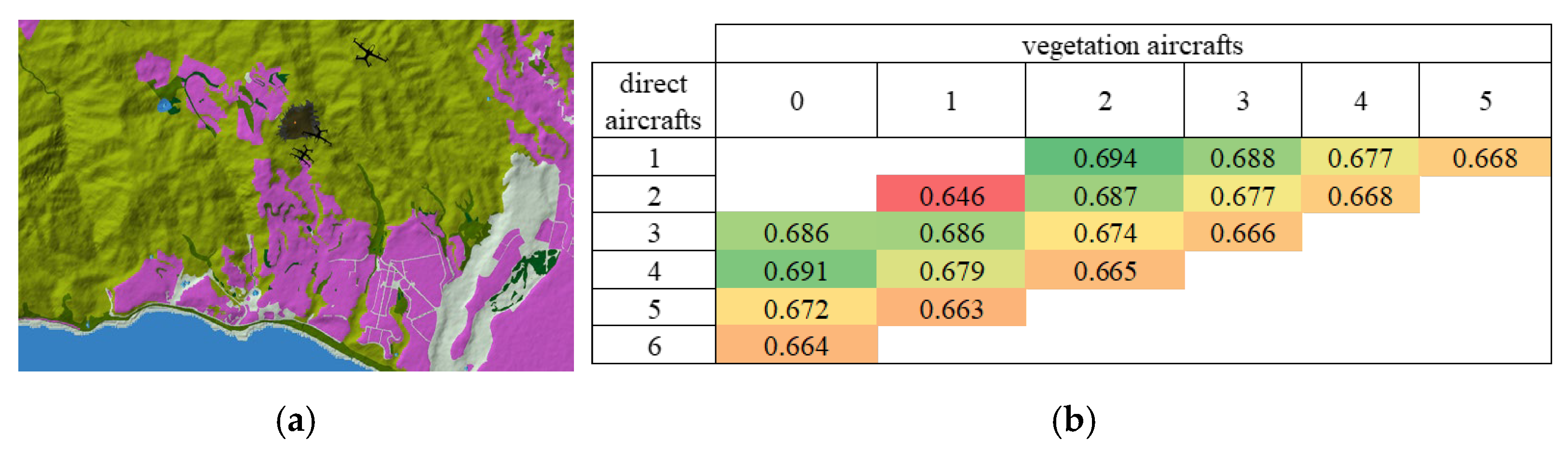
The highest MoE (0.694) occurred with a fleet of three aircraft of which two were assigned to attack vegetation and one was assigned to directly attack. Figure 4 suggests that splitting the suppression tactics between vegetation priority and direct attack yields the best MoE. Expanding the fleet size does not help as it only increases the operational and acquisition costs and does not affect the wildfire significantly.

6.2.3. Pyrenees, France

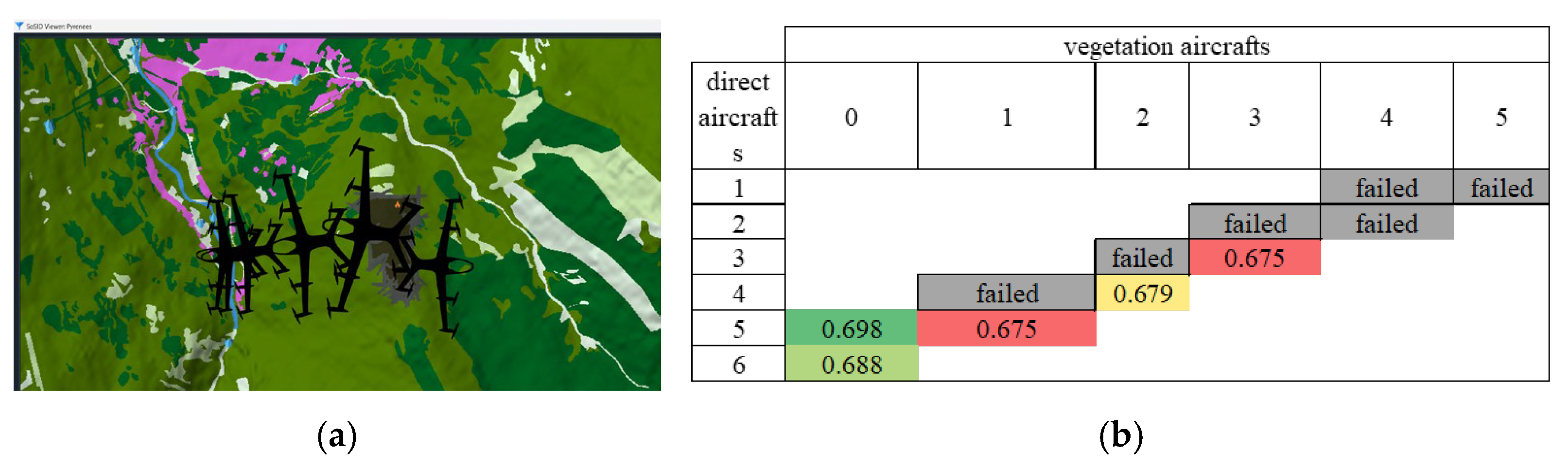
In the Pyrenees case as Figure 5 illustrated, the vegetation burn rate is exceptionally high, making the fire highly sensitive to suppression strategies. This sensitivity explains why several configurations failed in simulation.
This is the only scenario where the swapping of suppression tactics was established. When the burnt area exceeded 180 hectares, the groups swapped tactics, switching the direct attackers to vegetation containment and vice versa. Other configurations with similar fleet sizes also performed reasonably well; however, deviations in aircraft allocation or suppression focus tended to reduce MoE or even lead to outright failures.
Simulation results for Salamis, Palisades, and Pyrenees confirm strong performance and cost-effectiveness, with a six-aircraft fleet staying within the €100 million budget and satisfying 2035 technology readiness standards.

Author Contributions

Conceptualization, K.S.T. and S.Y.W.; methodology, K.S.T.; software and formal analysis, K.Z.H.; data curation, S.Y.W.; writing—original draft preparation, A.H.K. and K.S.T.; writing—review and editing, A.P., K.Z.H., N.K., N.N. and P.S.P.; visualization, A.H.K. and K.Z.H.; supervision, A.P., N.K., N.N. and P.S.P.; project administration, K.Z.H. All authors have read and agreed to the published version of the manuscript.

Funding

The research presented in this paper has been performed within the framework of the COLOSSUS project (Collaborative System of Systems Exploration of Aviation Products, Services and Business Models) and has received funding from the European Union Horizon Europe program under grant agreement No. 101097120. The Swiss participation in the Colossus project is supported by the Swiss State Secretariat for Education, Research and Innovation (SERI), under contract number 22.00609.

Institutional Review Board Statement

Not applicable.

Informed Consent Statement

Not applicable.

Data Availability Statement

The original contributions presented in this study are included in the article. Further inquiries can be directed to the corresponding author.

Acknowledgments

We would like to express our gratitude to Naratorn Udomchetchamnong, a mechanical and process system engineering graduate student, for his compassion and assistance during the aircraft design process.

Conflicts of Interest

The authors declare no conflicts of interest.

Appendix A

Table A1. Aircraft data.
ParametersValue
Length10.96 m
Height5.27 m
MTOM6328.5 kg
Empty Mass2848 kg
Capacity2500 kg
Wingspan16.51 m
Wing Area32.4 m2
Aspect Ratio8
AirfoilNACA 23018
Takeoff Field Length600 m
Cruise Speed330 km/h
Cruise AltitudeFL100
ROC6 m/s
Table A2. Mass of each component and its lever arms measured from the nose.
ComponentsMass [kg]Lever Arms/COG [m]
Wing472.53.5
Horizontal Tail62.210
Vertical Tail50.99.4
Fuselage213.73.1
Turbogenerator290.986.1
Fuel System99.13.4
Flight Controls63.92.7
Hydraulic6.33.1
Electrical139.63.5
Avionics140.90.3
Air Conditioning & Anti-Ice413.1
Front Electric Motors176.20.6
Rear Electric Motors172.47.3
Pilot77.81.9
Battery171.33.4
Floats & Landing gear673.53.1
Empty Weight28483
Water25003.4
Fuel903.13.5
Maximum Takeoff Mass6328.53.2

Appendix B

Figure A1. Distribution of initial unit acquisition costs by parameter.
Engproc 133 00065 g0a1
Figure A2. A schematic diagram describing the SoSID toolkit [3].
Engproc 133 00065 g0a2
Figure A3. Series hybrid propulsion system implemented in the toolkit.
Engproc 133 00065 g0a3

References

  1. Kalliatakis, N.; Naeem, N.; Prakasha, P.S. COLOSSUS X-Challenge Student Competition- Exploring Solutions to Wildfire Fighting Using System-of-Systems Analysis. In Proceedings of the 15th EASN Conference 2025, Madrid, Spain, 14–17 October 2025. [Google Scholar]
  2. The Fire Boss in Detail. Fire Boss LLC. Available online: https://firebossllc.com/specifications-and-performance/ (accessed on 3 July 2025).
  3. Kalliatakis, N.; Naeem, N.; Cigal, N. Colossus Collaborative System of Systems—Grand Challenge Project Description. Available online: https://colossus-sos-project.eu/wp-content/uploads/2025/02/ProjectDescription.pdf (accessed on 8 April 2026).
  4. Sinnige, T.; Nederlof, R.; van Arnhem, N. Aerodynamic Performance of Wingtip-Mounted Propellers in Tractor and Pusher Configuration. In AIAA AVIATION 2021 FORUM; American Institute of Aeronautics and Astronautics: Reston, VA, USA, 2021. [Google Scholar]
  5. Raymer, D.P. Aircraft Design: A Conceptual Approach, 3rd ed.; AIAA Education; American Institute of Aeronautics and Astronautics: Reston, VA, USA, 2002. [Google Scholar]
  6. Gudmundsson, S. General Aviation Aircraft Design; Butterworth-Heinemann: Oxford, UK, 2014; ISBN 978-0-12-397308-5. [Google Scholar]
  7. Anderson, J.D., Jr. Aircraft Performance and Design; McGraw-Hill: New York, NY, USA, 1999. [Google Scholar]
  8. Home—Eurostat. Available online: https://ec.europa.eu/eurostat (accessed on 27 November 2025).
  9. Direct Operating Cost—An Overview|ScienceDirect Topics. Available online: https://www.sciencedirect.com/topics/engineering/direct-operating-cost (accessed on 27 November 2025).
  10. Shiva Prakasha, P.; Naeem, N.; Amadori, K.; Donelli, G.; Akbari, J.; Nicolosi, F.; Knöös Franzén, L.; Ruocco, M.; Lefebvre, T.; Nagel, B. COLOSSUS EU Project—Collaborative SoS Exploration of Aviation Products, Services and Business Models: Overview and Approach. In Proceedings of the ICAS 2024, Florence, Italy, 9–13 September 2024. [Google Scholar]
  11. Direct vs. Indirect Attack Explained—BC Wildfire Service 2023. Available online: https://blog.gov.bc.ca/bcwildfire/direct-vs-indirect-attack-explained/ (accessed on 15 September 2025).
Figure 1. Technical drawing and isometric view of SUT Ember Aerotech.
Engproc 133 00065 g001
Figure 2. Constraint diagram.
Engproc 133 00065 g002
Figure 3. (a) Graphical User Interface (GUI) of an indirect containment of wildfire in Salamis. (b) MoE heatmap for combinations of direct and indirect aircraft in Salamis.
Engproc 133 00065 g003
Figure 4. (a) GUI of a direct containment of wildfire in Palisades. (b) The heat map visualizes these trends. Optimal outcomes are achieved when all available aircraft employ the same tactic, namely, either ‘direct’ or ‘vegetation.’
Engproc 133 00065 g004
Figure 5. (a) Aggressive direct attack by six aircraft quickly suppresses Pyrenees wildfire before spreading uncontrollably. (b) MoE heatmap for combinations of direct and vegetation-prioritized aircraft in Pyrenees.
Engproc 133 00065 g005
Table 1. Summary of mission requirements.
ParametersRequirements
Entry into Service (EIS)By 2035
Payload2500 kg
Cruise Speed330 km/h
Cruise Altitude3 km
Max Speed360 km/h
Stall Speed130 km/h
Range1300 km
Takeoff CapabilitiesVTOL or Amphibious STOL
Water capacity2.5 m3
Rate of Climb (ROC)6 m/s
FuelJet A1 or Sustainable Aviation Fuel
Table 2. Direct and indirect operating costs for the optimal performance scenarios in each region.
RegionDOC Per Mission (€)IOC (25%) (€)
Salamis59,216.714,804.7
Pyrenees2715.77678.94
Palisades16,699.014174.75
Disclaimer/Publisher’s Note: The statements, opinions and data contained in all publications are solely those of the individual author(s) and contributor(s) and not of MDPI and/or the editor(s). MDPI and/or the editor(s) disclaim responsibility for any injury to people or property resulting from any ideas, methods, instructions or products referred to in the content.