Proceeding Paper

Manufacturing of an Engine Outlet Guide Vane with Automated Fiber Placement and One-Shot Resin Transfer Molding Process †
by
Cristian Builes Cárdenas
1,*,
Elena Rodríguez Senín
1,*,
Mario Román Rodríguez
1,
Adrián López González
2 and
Gianna Avgousti
3
1
Advanced Composites Technologies, R&D Division, AIMEN Technology Centre, 36418 O Porriño, Spain
2
Escuela de Ingeniería Industrial, Universidad de Vigo, Rúa Maxwell, s/n, 36310 Vigo, Spain
3
EBOS Technologies, Arch. Makariou III and Mesaorias 1, Office 101, 2322 Lakatamia, P.O. Box 28122, Nicosia 2090, Cyprus
*
Authors to whom correspondence should be addressed.
Presented at the 15th EASN International Conference, Madrid, Spain, 14–17 October 2025.
Eng. Proc. 2026, 133(1), 47; https://doi.org/10.3390/engproc2026133047
Published: 24 April 2026

Abstract

The combination of the dry fiber AFP preforming process and RTM injection process brings new possibilities with regard to automation, high-quality manufacturing, and high-performance characteristics for out-of-autoclave composite manufacturing, particularly in aerospace industry. This paper describes the manufacturing of an aircraft engine Outlet Guide Vane (OGV), made with a dry carbon fiber preform manufactured with Automated Fiber Placement (AFP) and co-injected, co-cured, and co-bonded with titanium fittings through the Resin Transfer Molding (RTM) Process. The details of the assembly process and necessary steps are described. Parts of the digitalization process behind the manufacturing are described, including information about integrated sensors and data management.

1. Introduction

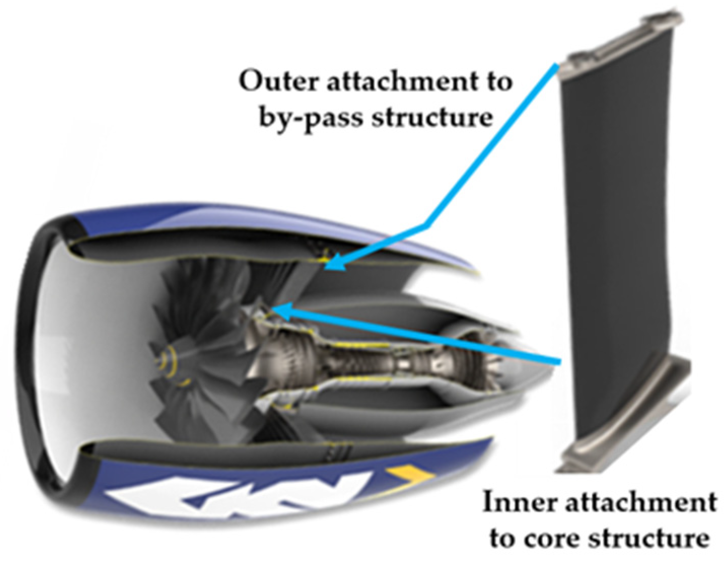
The engine Outlet Guide Vane (OGV) is a stator situated behind the fan in ducted electric or turbofan engines. Its role is to turn the rotating air flow behind the fan into axial flow, thereby improving the propulsive efficiency of the engine. It also provides structural support, transferring forces between the engine bypass structure and core structure, also transferring the weight of the engine to the wing structure [1].
OGVs are commonly made from metallic materials such as steel, adding considerable weight to the whole engine structure. Composite materials can be highly suitable for OGVs due to the low operational temperature in parts of the engine (not close to the combustion chamber) and their directional stiffness and strength. Different projects have been developed to leverage the advantages of composite materials used in such components, combining different technologies [2,3,4]. In particular, in CAELESTIS [5,6], additive manufacturing techniques are used to build a new OGV concept: Automated Fiber Placement (AFP) to construct a 3D dry carbon fiber preform, obtaining advantages in process automation and flaws/defects reduction, and Powder Bed Fusion (PBF) to produce titanium inserts that are co-joined together with the monolithic carbon fiber core. Both elements are co-bonded and co-cured through the Resin Transfer Molding (RTM) process in a “one-shot” manufacturing approach. This helps minimize the manufacturing time and reduce the risks of flaws and defects generated during the process, as well as reduce the overall OGV weight by combining different materials.

2. Results

2.1. Background

New aircraft concepts must be reliable and commercially viable in the effort to cut down global CO2 emissions, while ensuring their competitiveness by reducing the expected high costs, risk, and time required to realize such developments. In this case, virtual prototyping has the greatest potential for tackling this challenge, enabling technology across design, qualification, and certification and, eventually, in manufacturing. Current practices for designing and evaluating aircraft configurations are based on Multi-Disciplinary Optimization (MDO) methods that are limited to the use of advanced computational resources; thus, innovative steps need to be taken to attain a digital ecosystem that ensures interoperability among simulation tools and integrates high-performance computing (HPC) in the simulation process to deliver results within realistic timescales.
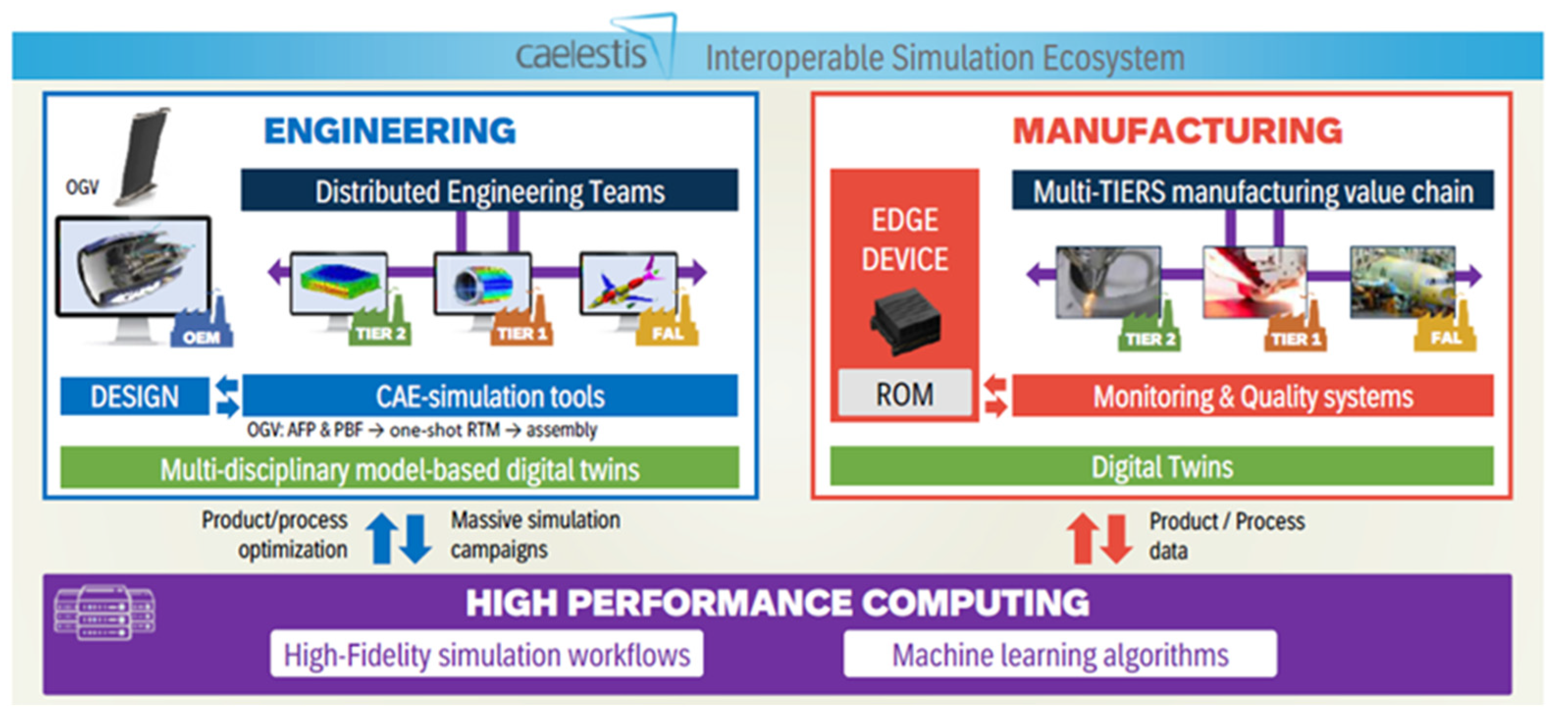
Based on this, CAELESTIS developed a novel, secure, end-to-end Interoperable Simulation Ecosystem (ISE) that performs multidirectional dataflow across the aircraft value chain, linking product design and distributed engineering teams and CAD-CAE tools to accelerate the design and engineering optimization of disruptive aircraft and engine configurations, ensuring their manufacturability since design conceptualization (Figure 1). This is achieved by integrating a variety of state-of-the-art simulation tools, boosted by implementing HPC, and applying innovative high-fidelity surrogate models to support the multi-disciplinary design, optimization and uncertainty quantification and propagation. This ecosystem will be developed to integrate, interoperate, and autonomously execute a variety of state-of-the-art simulation tools and innovative high-fidelity surrogate models to support the multi-disciplinary design, optimization, uncertainty quantification, and propagation across the design and manufacturing stages of new aerostructures, systems, and related engineering approaches.
The increasing adoption of advanced digital technologies such as AFP and RTM in aerospace manufacturing brings unprecedented opportunities for efficiency, accuracy, and sustainability. However, it also introduces new challenges in terms of data security, intellectual property protection, and trust in the digital thread. CAELESTIS has introduced concepts of cybersecurity to assess the secure integration and operation of the Intelligent Simulation Environment (ISE), which supports the integration of end-to-end (E2E) design to the manufacturing process, including the production of complex aerospace components such as the Engine Outlet Guide Vanes (OGVs).
This publication explains the manufacturing process of the latest OGV demonstrator.

2.2. Use Case and Technical Developments

For demonstration purposes, CAELESTIS aims to manufacture an aircraft engine Outlet Guide Vane (OGV, Figure 2) by combining different technologies:
  • Automated Fiber Placement (AFP) to manufacture a 3D dry carbon fiber preform.
  • Resin Transfer Molding (RTM) to inject the epoxy resin and consolidate the final component. The RTM strategy is used in a “one-shot” process to integrate titanium fittings, which are co-bonded and co-cured together with the OGV.
  • Powder Bed Fusion (PBF) to manufacture the titanium fittings. This process was implemented by GKN Aerospace Sweden.
The selected carbon fiber tapes for AFP were Teijin Toho Tenax IMS65 VO/13:194—TeXtreme 5173 [7] (Oxeon, Boras, Sweeden), with an areal weight of 194 g/m2, ply thickness of 0.182 mm, and tape width of 12.7 mm. The tapes incorporated a thermoplastic binder PA1206, 6 g/m2 (Oxeon, Boras, Sweeden) to maintain adhesion between layers while in use. The OGV preform was manufactured using an AddComposites XS AFP head (AddComposites, Helsinki, Finland), applying a compaction force of 200 N on the tape surface and a deposition speed of 400 mm/s. The AFP head was mounted on an ABB IRB-6600 robot (ABB, Zurich, Switzerland) that heats the tapes to activate the binder using LASER.
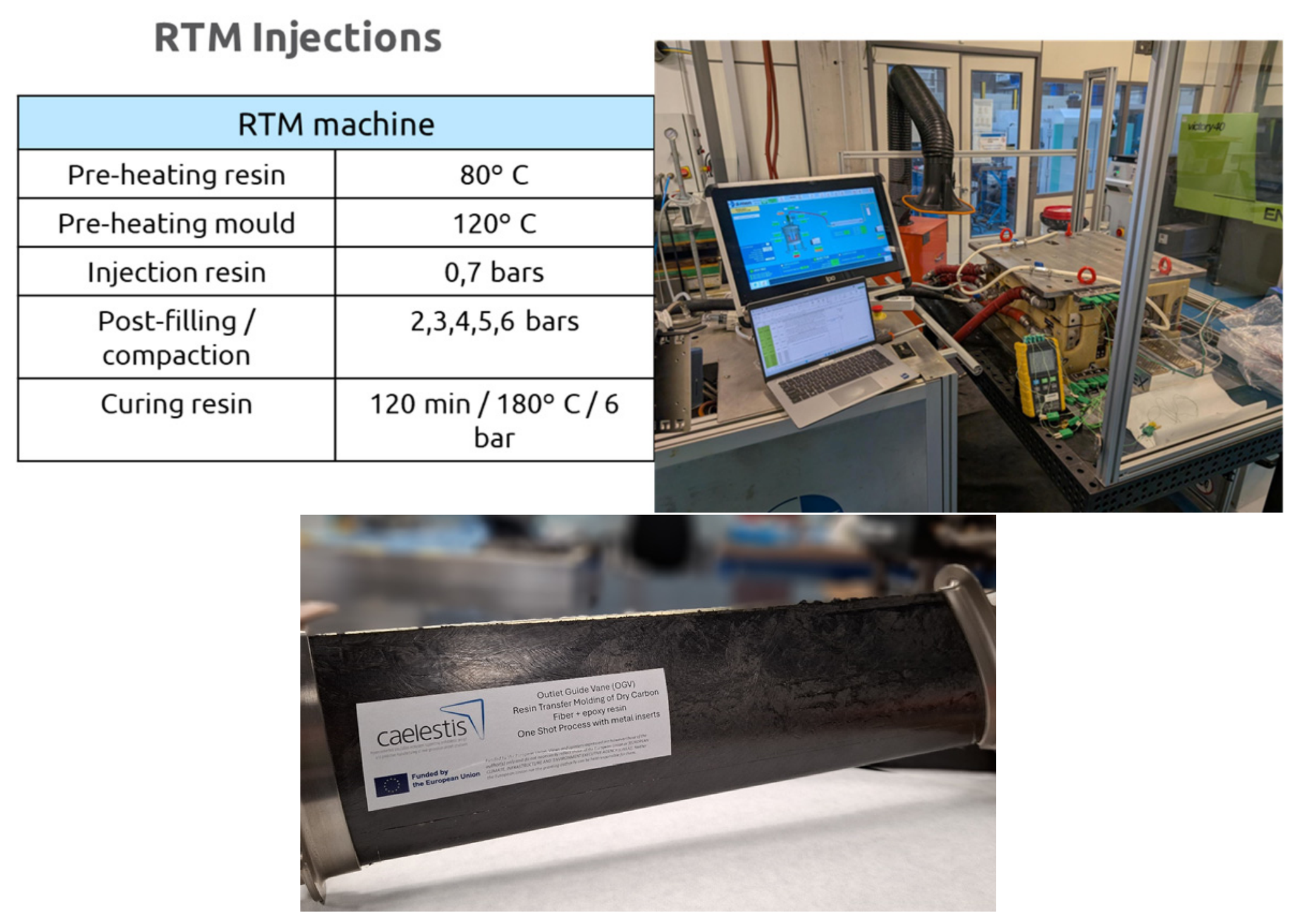
The matrix used was the aeronautical-grade epoxy resin Hexcel HexFlow RTM6-2 (UNECO, Barcelona, Spain); the resin was injected at 0.7 bars to ensure the homogeneous impregnation of the preform, followed by a stepped stage of gradual compaction, increasing pressure to 6 bars to eliminate any residual porosity or dry spots in the final part. The injection was carried out using an ISOJET RTM machine (ISOJET Equipements, Corbas, Farnce) and a specific steel tooling for the OGV (ALPEX Technologies, Mils, Austria).
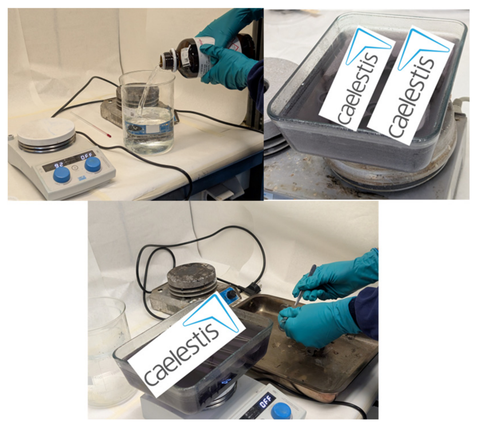
To improve the adhesion between the titanium and the carbon fiber, an etching process [8] was applied using sulfuric acid at 50% concentration (Scharlab, Sentmenat, Spain). The etching was applied at a temperature of 60 °C for 30 min, and then cooled and cleaned using distilled water (Figure 3).
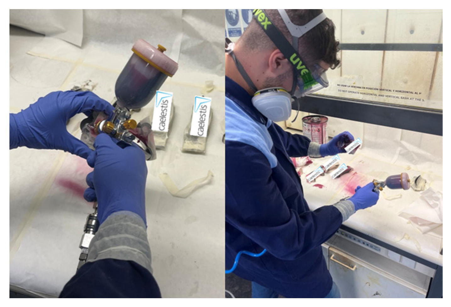
To hold and protect the surface interface between the carbon fiber, it was necessary to apply an epoxy primer to the titanium fittings in order to avoid corrosion. The primer was Hexcel HexBond 122 (Composites Distribution, Beziers, France), applied using a pistol with compressed air at 2 bars of pressure (Figure 4).
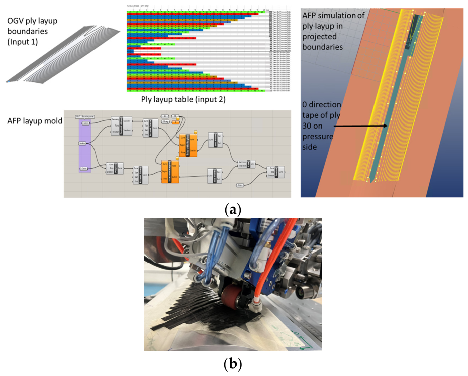
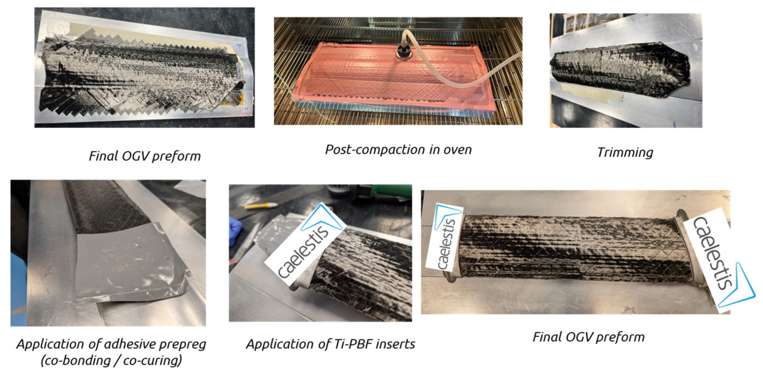
In parallel, the 3D OGV preform was fabricated using an aluminum tool (PROMEGA, Nigrán, Spain) by laminating layer by layer (for a total of 40 layers). The stacking sequence was programmed in a robot-specific software and then executed on the mold (Figure 5). Since the OGV width is narrow (100 mm), some trimming was performed manually to eliminate excess fiber in the layers. This is necessary because the AFP head cannot cut curved or angled directions, as shown in the OGV design.
After the layering process, the preform was heated in an oven (ThermoFisher Scientific, Madrid, Spain), using vacuum to further consolidate the binder and compress all the layers to fit it properly onto the RTM mold cavity. Then, the preform was trimmed and prepared for injection. An epoxy adhesive prepreg was placed over the preform surface to be co-cured with the resin to improve the adhesion between the titanium and the carbon fiber (Figure 6). The adhesive was Hexcel’s HexBond 319A 300 g/m2 (Composites Distribution, Beziers, France). Both the primer and adhesive prepreg were compatible with the RTM6-2 resin.
Preform and titanium inserts were placed inside the RTM mold to carry out the injection. Afterwards, the final OGV was demolded (Figure 7).

2.3. Digital Manufacturing and Data Collection

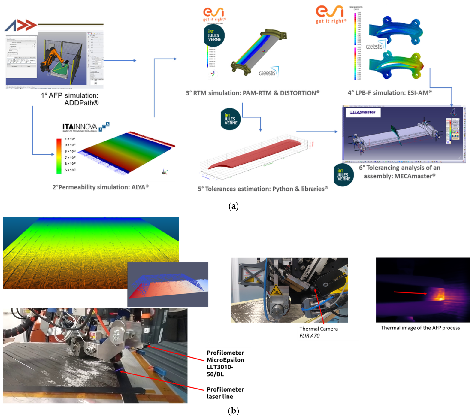
As part of CAELESTIS, the entire manufacturing line was monitored “on-line” to feed data in real time in order to run Reduced-Order Models (ROMs). These ROMs were executed directly on the manufacturing site, aiming to correct possible flaws and determine relevant aspects, such as resin impregnation, level of porosity, and mechanical performance. The AFP process was monitored using a 3D profiler, capable of retrieving 3D cloud point data to re-create a digital twin of the dry fiber preform. This information was processed and passed through the simulation ecosystem (ISE, Figure 8a) developed inside the project. Other aspects such as temperature were monitored during the process to ensure binder activation; monitoring was carried out using a thermal camera (Figure 8).
In addition to digital tasks, the cybersecurity implemented in CAELESTIS follows the PRESS (Privacy, data Protection, Ethics, cyberSecurity, Societal) bases [9]. PRESS-based requirements were translated into practical measures during the integration of high-performance computing (HPC), edge devices, and workflow orchestration systems relevant to the AFP/RTM pipeline. The main objectives were to ensure secure data transfer across distributed environments, safeguard proprietary manufacturing and simulation data, and enable role-based, auditable access control across partners and infrastructures.
Key measures include encrypted communication protocols (HTTPS, SSH, SFTP), secure storage, policies for sensitive data (simulation results, Reduced-Order Models, and material properties), and token and key-based authentication for HPC services. Role-based access controls (RBACs) were implemented to ensure that only authorized personnel can interact with manufacturing data, models, and process workflows, while periodic reviews and audits strengthen resilience against emerging threats. A 3-month risk monitoring cycle was established to ensure continuous compliance with ENISA [10] and ECSO [11] guidelines, with incident reporting channels established between CAELESTIS partners and project coordinators.
For aerospace manufacturing use cases such as the OGV demonstrator, these measures guarantee that digital assets exchanged across the value chain, ranging from design files to simulation outputs and process parameters, remain protected against unauthorized access, manipulation, or leakage. Cybersecurity in CAELESTIS thus acts as a foundation for trustworthy virtual-to-real manufacturing, securing sensitive data while enabling collaborative innovation among European aerospace stakeholders.

3. Concluding Remarks and Next Steps

It was possible to manufacture an OGV using Automated Fiber Placement and by combining the PBF method and RTM process to create and integrate titanium fittings into the final geometry, creating a multi-material component in one single step (one-shot). Further improvements must be studied to enhance the process’ performance as the fiber tapes must still be trimmed manually, and modifications to the AFP system and programming must be made. Further analysis needs to be conducted to improve the surface treatment and quality of the adhesion between the carbon fiber and the titanium, possibly removing the need to use the adhesive prepreg layer. LASER can be applied to the titanium surface to modify its roughness and increase its compatibility with the carbon fiber and the epoxy resin, enhancing the adhesion between these materials.
The on-line monitoring process allows the training and implementation of specific simulation models to evaluate the process conditions, possible defects, and their effects over mechanical performance, as well as further improvement to be made to the design of the OGV components.

Author Contributions

Conceptualization, C.B.C.; methodology, C.B.C. and M.R.R.; validation, A.L.G.; formal analysis, C.B.C., M.R.R. and A.L.G.; investigation, M.R.R., A.L.G. and G.A.; resources, C.B.C. and M.R.R.; data curation, M.R.R.; writing—original draft preparation, C.B.C.; writing—review and editing, M.R.R.; project administration, E.R.S. All authors have read and agreed to the published version of the manuscript.

Funding

This research was funded by the EU Horizon-RIA project CAELESTIS “Hyperconnected simulation ecosystem supporting probabilistic design and predictive manufacturing of next generation aircraft structures”, with grant number 101056886, under the HORIZON-CL5-2021-D5-01 call. Project information is available from its web page: https://www.caelestis-project.eu/ (accessed on 30 November 2025).

Data Availability Statement

Data are available on request due to intellectual property restrictions.

Acknowledgments

The authors would like to thank all AIMEN staff that participated in this research; CINEA and the EASN association for all their support and guidance regarding this edition of the conference; and Alexander Sorgenicht for kindly hosting the “Advancing Sustainable Aviation” session during the conference.

Conflicts of Interest

The authors declare no conflicts of interest.

References

  1. GKN Aerospace Sweden. Concept of Outlet Guide Vane and Preliminary Design Space and Bill of Materials. Available online: https://zenodo.org/records/12720881 (accessed on 30 November 2025).
  2. Anoshkin, A.; Zuiko, V.; Shipunov, G.; Tretyakov, A. Technologies and Problems of Composite Materials Mechanics for Production of Outlet Guide Vane for Aircraft Jet Engine. PNRPU Mech. Bull. 2014, 1, 5–44. [Google Scholar] [CrossRef] [PubMed]
  3. CORDIS Europe. Uncertainty Prediction & Bias Elimination in Aviation Technology for Safety. Available online: https://cordis.europa.eu/project/id/101147799 (accessed on 30 November 2025).
  4. RISE Research Institutes of Sweden. Advanced And Lightweight Composite Outlet Guide Vanes—CACTUS. Available online: https://www.ri.se/en/expertise-areas/projects/advanced-and-lightweight-composite-outlet-guide-vanes-cactus (accessed on 30 November 2025).
  5. CAELESTIS—Hyperconnected Simulation Ecosystem Supporting Probabilistic Design and Predictive Manufacturing of Next Generation Aircraft Structures. Available online: https://cordis.europa.eu/project/id/101056886 (accessed on 26 November 2025).
  6. RTDS. CAELESTIS—Next Generation Aircraft. Available online: https://caelestis-project.eu/ (accessed on 26 November 2025).
  7. Oxeon TeXtreme. Unidirectional Tapes. Available online: https://textreme.com/products/ud-tapes (accessed on 30 November 2025).
  8. Ban, S.; Taniki, T.; Sato, H.; Kono, H.; Iwaya, Y.; Miyamoto, M. Acid Etching of Titanium for Bonding with Veneering Composite Resins. Dent. Mater. J. 2006, 25, 382–390. [Google Scholar] [CrossRef] [PubMed]
  9. Barcelona Supercomputing Center. CAELESTIS Interoperable Simulation Ecosystem Architecture and PRESS Analysis. Available online: https://zenodo.org/records/12704514 (accessed on 30 November 2025).
  10. Skouloudi, C.; Malatras, A.; Naydenov, R.; Dede, R. Guidelines for Securing the Internet of Things: Secure Supply Chain for IoT; ENISA: Chalandri, Greece, 2020. [Google Scholar]
  11. ECSO European Cyber Security Organization. Cybersecurity for Smart Manufacturing: Best Practices. Available online: https://ecs-org.eu/publications/ (accessed on 30 November 2025).
Figure 1. CAELESTIS concept.
Engproc 133 00047 g001
Figure 2. Scheme of the OGV integrating the carbon fiber core and titanium fittings. Courtesy of GKN Aerospace Sweden.
Engproc 133 00047 g002
Figure 3. Etching process of the titanium fittings. The fittings’ geometry is property of GKN Aerospace Sweeden.
Engproc 133 00047 g003
Figure 4. Application of epoxy primer (Hexcel Hexbond 122) to protect the surface treatment.
Engproc 133 00047 g004
Figure 5. Manufacturing of OGV performs in the AFP process. (a) Path planning. (b) Deposition of fibers onto the mold.
Engproc 133 00047 g005
Figure 6. Trimming process of the OGV preform and application of adhesive prepreg and titanium fittings.
Engproc 133 00047 g006
Figure 7. RTM process and parameters and the final OGV geometry.
Engproc 133 00047 g007
Figure 8. Digital thread of CAELESTIS. (a) Interoperable simulation ecosystem to support manufacturing. (b) Monitoring process using 3D profiler and thermal camera during the AFP preforming process.
Engproc 133 00047 g008
Disclaimer/Publisher’s Note: The statements, opinions and data contained in all publications are solely those of the individual author(s) and contributor(s) and not of MDPI and/or the editor(s). MDPI and/or the editor(s) disclaim responsibility for any injury to people or property resulting from any ideas, methods, instructions or products referred to in the content.