1. Introduction
Small Unmanned Aerial Vehicles (RPAS) are becoming increasingly relevant in both military and civilian domains due to their versatility, low operational cost, and ability to access areas where manned aircraft are either impractical or too risky to deploy [
1]. These platforms are currently employed in a wide range of applications, including surveillance, reconnaissance, logistics support, environmental monitoring, precision agriculture, and search and rescue operations [
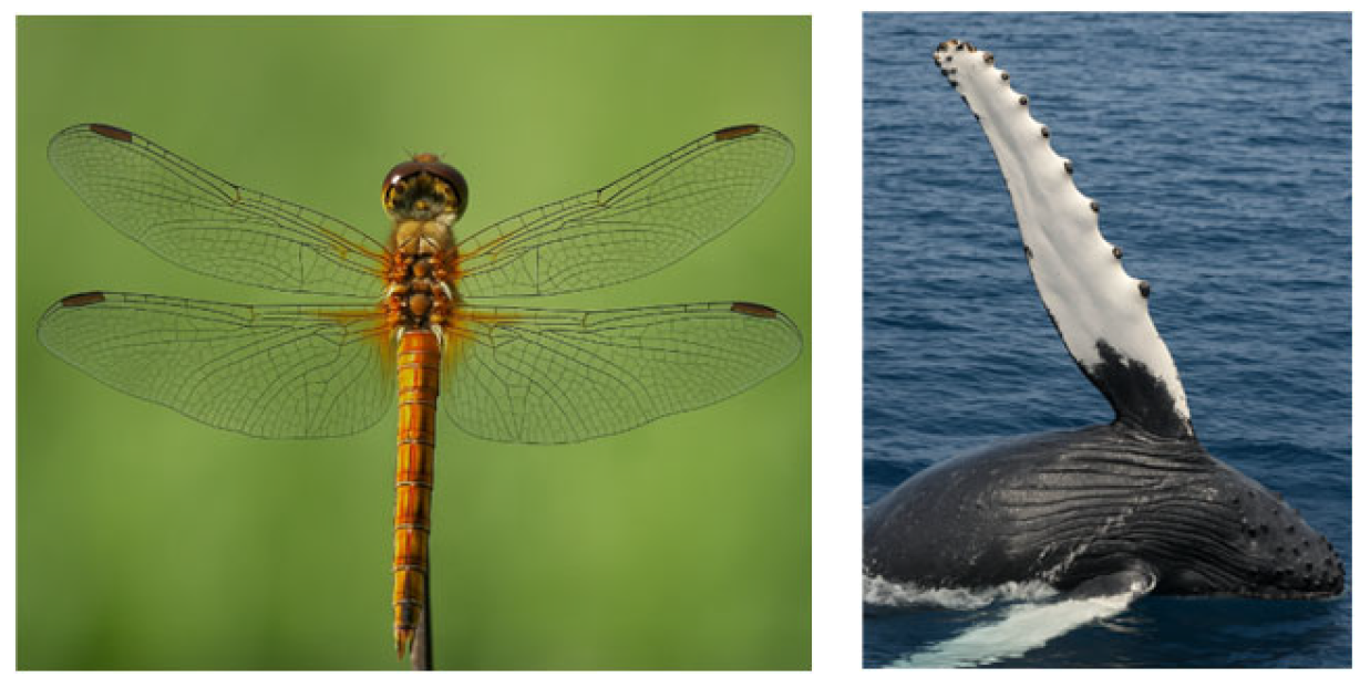
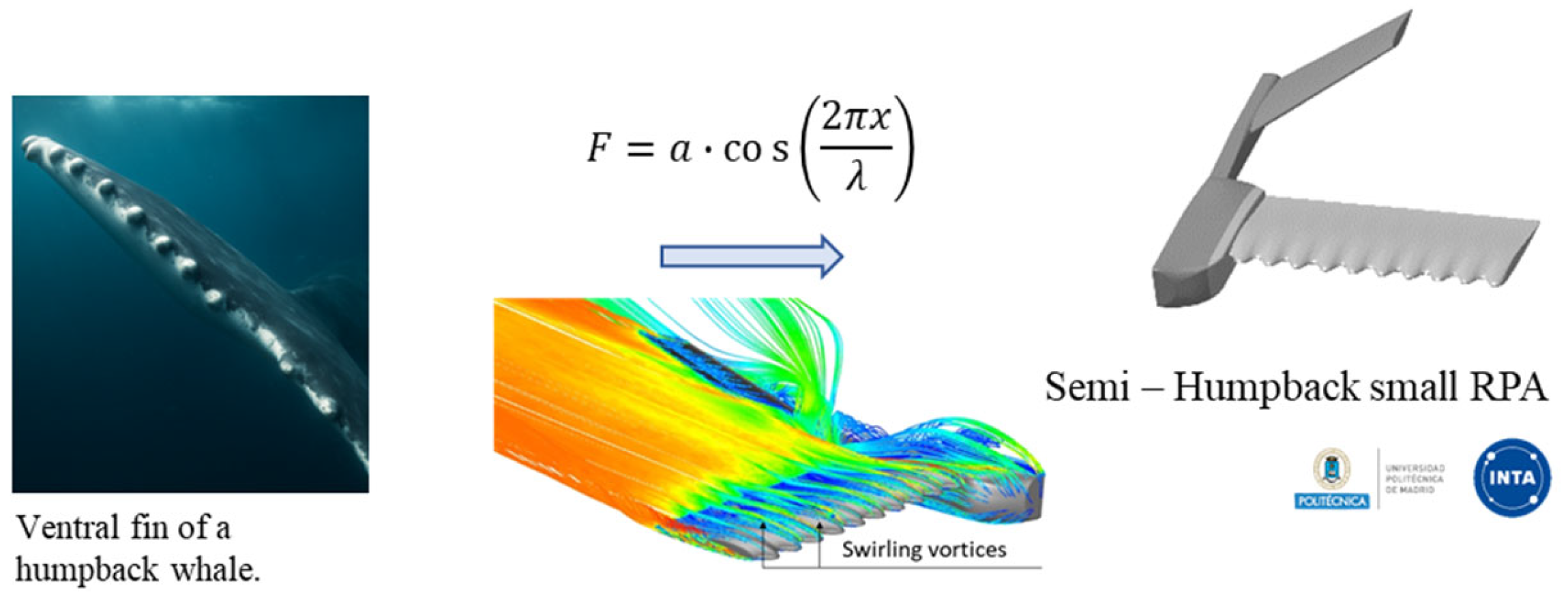
2]. In recent years, a design trend has emerged that departs from traditional configurations and explores unconventional shapes inspired by nature (see
Figure 1). Bioinspiration in aeronautical engineering aims to harness millions of years of biological evolution to improve aerodynamic performance, energy efficiency, and vehicle maneuverability. Within this context, wing geometries based on natural organisms have become a particularly attractive field of research [
3]. This paper focuses on two bioinspired wing configurations. The first one is based on the corrugated geometry (peaks and valleys) observed in dragonfly wings. Dragonflies are known for their remarkably sophisticated flight capabilities: they can execute complex maneuvers such as sharp turns, sustained hovering, and even gliding—an uncommon feature among insects. The corrugated structure of their wings plays a crucial role in achieving these flight characteristics, as it significantly contributes to lift generation and flight stability by mitigating pressure fluctuations over the wing surface [
4]. Although such corrugations might initially seem disadvantageous due to their potential to increase aerodynamic drag, experimental and numerical studies have revealed the opposite. The small vortices formed within the corrugation valleys generate localized low-pressure regions that help maintain airflow attachment along the wing surface, thereby delaying flow separation and enhancing lift [
5,
6]. This mechanism enables superior aerodynamic performance at low Reynolds numbers, which are typical of small RPAS flight conditions. As a result, dragonfly-inspired wing designs have been adopted in bioinspired RPAS development, aiming to improve maneuverability, aerodynamic efficiency, and flow control in low-speed flight regimes [
7,
8]. Furthermore, these configurations offer several aerodynamic advantages, including high lift at low Reynolds numbers, improved boundary layer control, enhanced maneuverability and stability, and the ability to hover, glide, and even fly backward.
The second configuration draws inspiration from the tubercles located on the leading edge of ventral fins of humpback whales. Several studies have shown that these tubercles delay flow separation, thereby enhancing aerodynamic control at high angles of attack close to stall onset. This effect results in improved maneuverability and a noticeable reduction in lift loss. Consequently, humpback whales are able to perform agile underwater maneuvers with remarkable hydrodynamic efficiency [
9,
10]. Translating these natural features into wing designs for aeronautical applications opens new opportunities for aircraft requiring high maneuverability, efficiency and stability, particularly in the case of small RPAS, where flight conditions are often more critical and highly sensitive to external disturbances. Therefore, this paper focuses on a numerical analysis of two bioinspired wing configurations, aiming to assess their potential feasibility for implementation in conventional fixed-wing RPAs. In this work, the novelty is the application-driven, controlled 3D comparison of two bio-inspired concepts—dragonfly-inspired corrugations and humpback-inspired leading-edge tubercles—implemented on the same rectangular-wing RPAS configuration and benchmarked against the baseline Eppler 186 wing under identical operating conditions and CFD settings. This framework enables consistent conclusions regarding lift, drag, efficiency and stall-related trends at a representative low-Re flight regime for small RPAS.
2. Bioinspired Airfoils
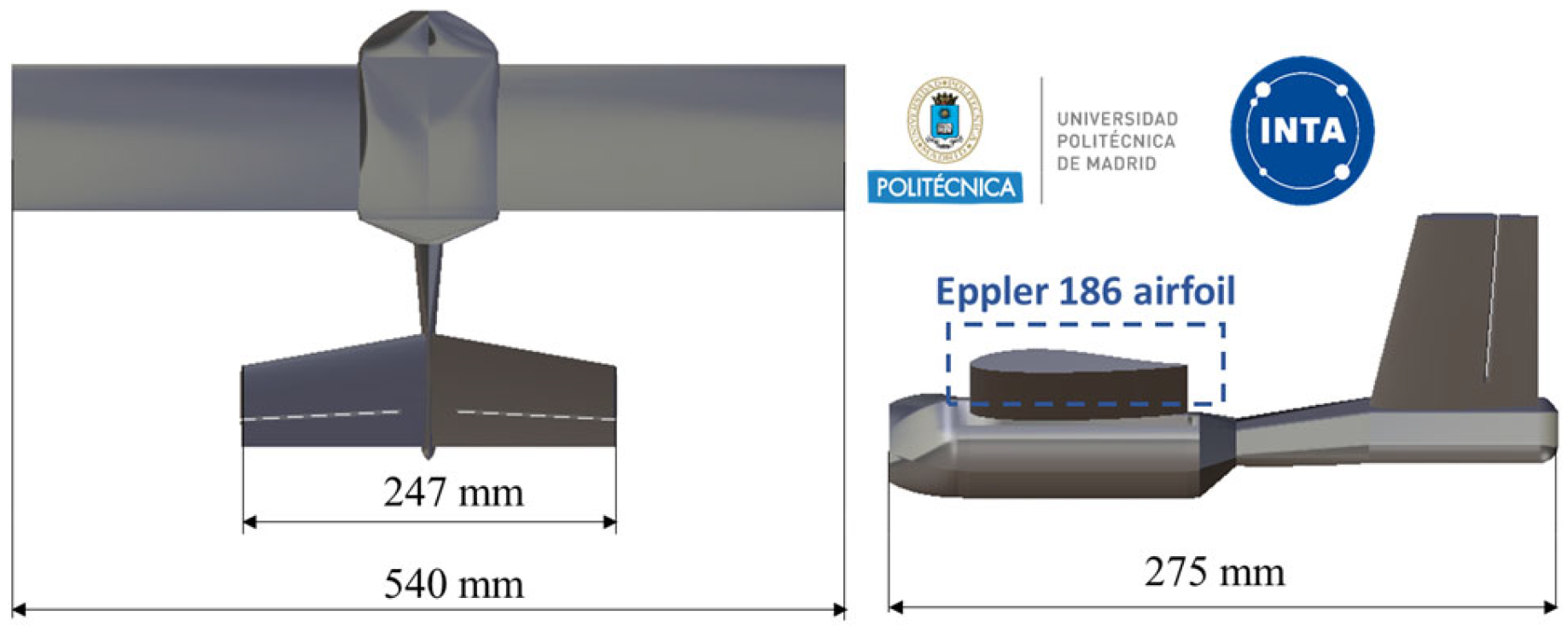
A Small RPA composed of a rectangular wing planform with Eppler 186 airfoils and a V-tail (see
Figure 2) was designed between the National Institute for Aerospace Technology (INTA) and the Technical University of Madrid (UPM) as the baseline configuration.
Figure 2 shows the dimensions of the vehicle which presents an overall length of 275 mm, a wingspan of 540 mm, a chord of 90 mm, a wing surface of 0.048 m
2 and an aspect ratio of 6 [
11]. The rectangular wing has been redesigned following two bioinspired morphological concepts: dragonfly-inspired and humpback whale–inspired configurations. The RPAS geometry used in the CFD simulations corresponds to the real aircraft dimensions shown in
Figure 2. All bio-inspired modifications are defined with respect to the wing chord and then scaled to the RPAS chord c = 90 mm, keeping the planform unchanged to enable direct comparisons.
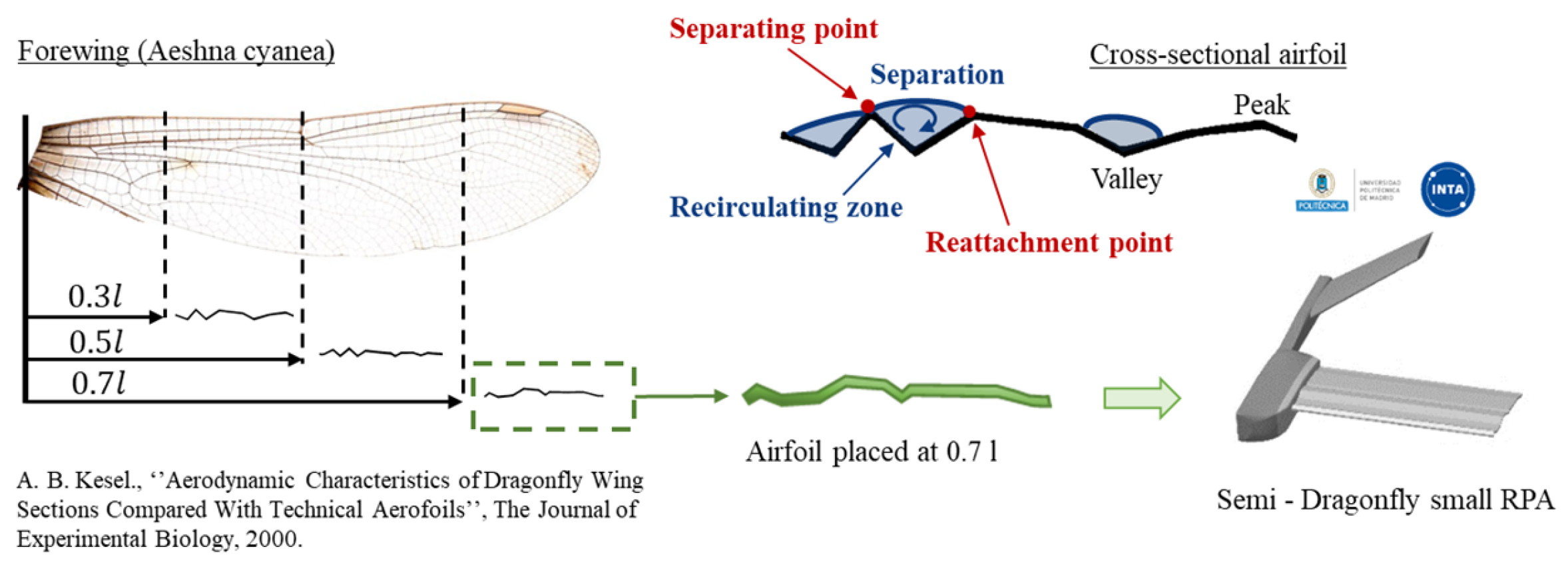
In the first case, the wing employs a corrugated cross-sectional profile replicating the structure of a dragonfly wing along its full wingspan. The corrugated airfoil is based on the Aeshna cyanea wing cross-section located at 0.7 L along the spanwise direction, following [
12]. The selected section is scaled to the RPAS chord. The airfoil thickness used in the present model is t = 2 mm consistent with the CAD implementation shown in
Figure 3 (transversal dragonfly section scheme).
In the second, sinusoidal tubercles are incorporated along the leading edge, mimicking the characteristic pattern of the ventral fins of humpback whales. The tubercled leading-edge geometry is implemented as a sinusoidal modulation of the leading-edge position along the span. The wavelength and amplitude are defined relative to the chord as
λ = 0.25
c and
a = 0.05
c, which correspond to
λ = 22.5 mm and
a = 4.5 mm for c = 90c mm. This parameter set is adopted because it provided the highest maximum lift coefficient in our previous CFD study [
13].
Dragonflies are among the most remarkable examples of biological inspiration in aeronautical engineering. They stand out among four-winged insects due to their ability to move their fore- and hindwings independently, allowing for exceptional flight control, hovering, and even gliding—capabilities rarely found in insects. This versatility is largely attributed to their unique corrugated wing morphology, characterized by a cross-sectional pattern of peaks and valleys (see
Figure 3). These corrugations enhance the wing’s structural stiffness and strength with minimal weight. Although they initially appear to increase aerodynamic drag, research has revealed that they actually improve lift and aerodynamic performance, especially at low Reynolds numbers typical of small RPAS. This advantage arises from the formation of small vortices within the corrugation valleys (see
Figure 3). These vortices create low-pressure regions that help keep the airflow attached to the wing surface longer, thereby delaying flow separation and increasing lift. In essence, the corrugations act as micro-vortex generators that stabilize the boundary layer and smooth the flow over the wing, improving aerodynamic efficiency even at high angles of attack.
Moreover, the leading-edge geometry varies along the span of the wing, suggesting a functional adaptation to different flight conditions. This natural optimization has inspired bioinspired designs in small RPAS, where lightweight, strong, and aerodynamically efficient wings at low speeds are desired. In this paper, the selected airfoil is placed at 0.7 L (see
Figure 3) as in a previous study [
12] it was the one that provided the highest lift coefficient across the entire range of angles of attack. In the second bioinspired configuration, the inspiration from nature came specifically from the ventral fins of humpback whales, which possess tubercled leading edges. There is particularly interesting the integration of similar features into RPA lifting surfaces. The tubercles are thought to contribute to lift enhancement during prey-capturing maneuvers by allowing sharp directional changes without a significant loss of lift. A considerable number of studies have confirmed the aerodynamic advantages of this design, particularly its ability to delay stall and improve post-stall behavior. Over the past decade, extensive research has been devoted to leading-edge modifications incorporating tubercles, primarily due to their potential for passive flow control. The available literature includes a wide range of experimental and computational analyses, all aimed at quantifying aerodynamic performance improvements and understanding the underlying flow-control mechanisms responsible for these effects. To replicate the flow control mechanisms observed in the ventral fins of humpback whales, the rectangular wing geometry is modified to include sinusoidal tubercles along the leading edge. The leading-edge contour is mathematically described by a sinusoidal function parameterized by its amplitude (a) and wavelength (λ), defined in
Figure 4. The present work considers only one tubercled leading-edge configuration, defined by an amplitude of a = 0.05c and a wavelength of λ = 0.25c. This particular set of parameters was selected based on prior analyses, which identified it as the configuration yielding the greatest maximum lift coefficient among the tested geometries [
13].
3. Numerical Study
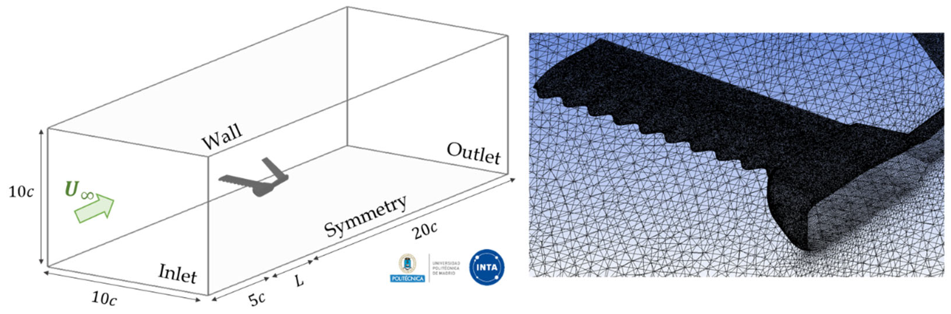
The aerodynamic performance of the small RPA in the three configurations (dragonfly, humpback and Eppler 186 airfoil) is evaluated using the ANSYS Fluent software 2024. Since the freestream velocity is consistently aligned with the chordwise direction and the models do not include a propeller, only half of the geometry is simulated by applying a symmetry boundary condition (see
Figure 5). The inlet boundary is placed at 5c upstream of the model, while the outlet is placed 20c downstream. The side, top, and bottom boundaries are treated as stationary walls. The overall dimensions of the computational domain and the different boundaries are shown in
Figure 5. The spatial discretization of the flow domain requires a controlled mesh growth rate to properly capture flow variations. The region adjacent to the model surface is refined with smaller elements to accurately resolve the velocity gradients within the boundary layer. An unstructured tetrahedral mesh is employed throughout the entire computational domain. A maximum element size of 13 mm is set for the far-field region, while a minimum size of 1.2 mm is imposed on the surface of the model. The resulting mesh consists of approximately five million elements for each simulation. Numerical simulations are performed with an inlet velocity of 10 m/s corresponding to a Reynolds number of Re = 1.3 ∙ 10
5, which is representative of typical operating conditions for small RPAS. The boundary layer is modeled using standard wall functions, and turbulence is captured through the two-equation k-ω Shear Stress Transport (SST) model, which combines robustness and accuracy in predicting near-wall flow behavior. The k-ω SST turbulence model is employed in a fully turbulent mode. Standard wall functions are used for the near-wall treatment, i.e., the wall shear stress is computed through a logarithmic-law-based formulation consistent with a wall-function approach in ANSYS Fluent. This modelling choice is applied uniformly to all configurations to preserve consistency in the comparative analysis. The angle of attack (α) is varied from −5° to + 25°.
4. Discussion of Results
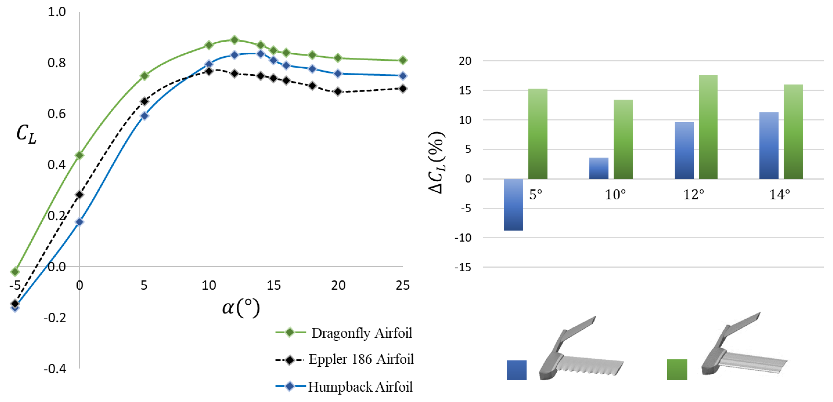
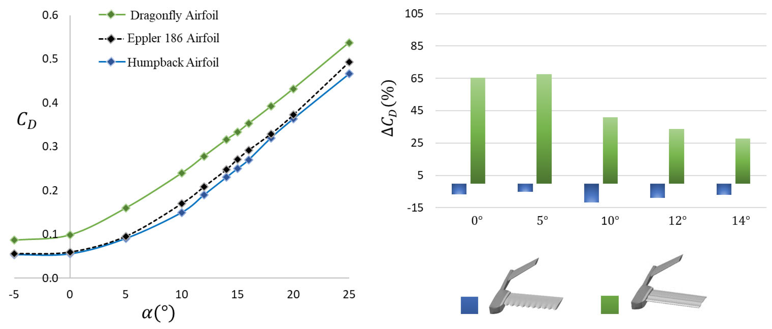
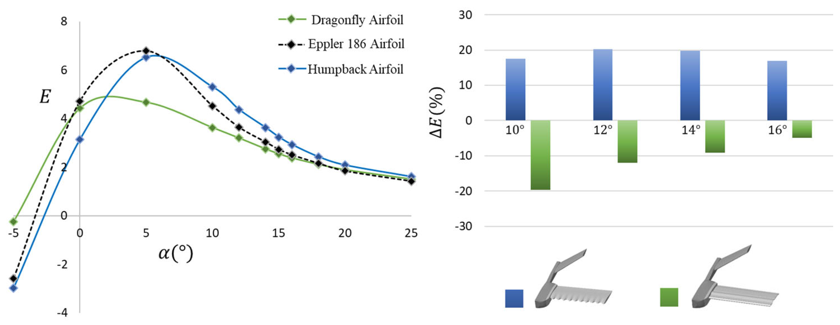
Figure 6,
Figure 7 and
Figure 8 show the lift coefficient, drag coefficient and aerodynamic efficiency for all configurations (dragonfly, Eppler 186 and humpback airfoils). The percentage variations in each aerodynamic parameter are presented in the figures.
The dragonfly-inspired airfoil exhibits the highest lift coefficient values across the entire range of angles of attack, allowing the RPA to operate at lower flight speeds—an important advantage for surveillance missions, among other applications. The Eppler 186 airfoil shows higher lift values than the humpback-inspired airfoil at low angles of attack (below 10°); however, at higher angles of attack, the humpback configuration generates greater lift coefficient. At higher angles of attack (from 10°), it is clearly observed that the conventional airfoil exhibits the lowest lift performance, highlighting the aerodynamic benefits of the bioinspired geometries under these flight conditions. The humpback airfoil demonstrates an increasing percentage variation in lift relative to the baseline configuration as the angle of attack rises, achieving approximately a 10% higher lift coefficient than the Eppler 186 configuration at 12° and 14°. An even greater improvement is observed for the dragonfly configuration, which provides roughly a 15% increase in lift coefficient across all angles of attack—not only at the higher ones. Indeed, as shown in the graph, the dragonfly airfoil maintains a lift coefficient at least 15% higher than the baseline for the entire range of tested angles of attack. Furthermore, both bioinspired configurations contribute to a delay in the stall condition as a direct consequence of their distinctive geometrical features. While the baseline Eppler 186 airfoil stalls at an angle of 10°, the dragonfly airfoil delays stall by approximately 2° (stalling at 12°), and the tubercled humpback configuration exhibits the latest stall, occurring at around 14°. In the case of the dragonfly-inspired airfoil, the corrugated cross-sectional geometry—characterized by alternating peaks and valleys—induces the formation of small leading-edge vortices within the corrugation valleys. These vortices generate localized low-pressure regions that help maintain the flow attached to the surface, effectively energizing the boundary layer and delaying flow separation.
Similarly, in the humpback-inspired configuration, the sinusoidal tubercles along the leading edge create swirling vortices that redistribute momentum within the boundary layer. This mechanism energizes the near-surface flow, allowing it to remain attached over a wider range of angles of attack, thereby postponing stall condition of a conventional configuration. As expected, the dragonfly-inspired configuration exhibits the highest drag coefficients (CD) across the entire range of angles of attack. The corrugated geometry, characterized by alternating peaks and valleys, penalizes drag particularly during cruise flight conditions (0–5°), showing an increase of approximately 60% compared to the conventional configuration. In contrast, the humpback-inspired configuration achieves the lowest drag values throughout the whole range of angles of attack. The presence of tubercles along the leading edge of the rectangular wing contributes to a reduction in drag, with the most significant decreases observed between 0° and 14°, reaching up to 20% reduction at 10°, and around 10% at higher angles of attack. This drag reduction can be attributed to the fact that the tubercled airfoil retains the aerodynamic characteristics of the Eppler 186 airfoil, but the modification of the leading edge of the wing introduces beneficial flow effects. The sinusoidal tubercles generate vortices that energize the boundary layer, delay flow separation, and suppress large-scale vortex shedding, thereby generating a smoother pressure distribution over the rectangular wing surface. These mechanisms result in a lower overall drag, particularly in pre-stall conditions, offering a distinct aerodynamic advantage. The observed trends are consistent with the mechanism commonly reported in the literature for tubercled leading edges (streamwise vortices and boundary-layer re-energization), although near-wall diagnostics are not reported here.
The aerodynamic efficiency (E) is significantly higher across the entire range of angles of attack for both the baseline (Eppler 186) and the humpback-inspired configuration (featuring leading-edge tubercles), as expected, since the dragonfly configuration exhibits considerably higher drag at all angles of attack. Consequently, the dragonfly airfoil shows a reduction in aerodynamic efficiency under all flight conditions. The maximum aerodynamic efficiency (Emax) is achieved at an angle of 5° for both the baseline and humpback configurations, reaching values of approximately 7.5, whereas the dragonfly airfoil attains its peak efficiency at 0°, with a much lower value of 4.4. Up to the angle corresponding to maximum efficiency, the Eppler 186 maintains slightly higher performance; however, at larger angles of attack, the humpback configuration outperforms it. This improvement is attributed to the tubercles along the leading edge, which, while preserving the aerodynamic of the Eppler airfoil, induce swirling vortices that help energize the boundary layer and delay flow separation. As a result, the humpback configuration operates more effectively near the stall region, achieving up to a 20% increase in aerodynamic efficiency compared to the baseline configuration between 10° and 16°. In contrast, the dragonfly-inspired airfoil shows a decrease in efficiency of approximately 20% at 10° and around 10% for higher angles of attack.
5. Conclusions
The dragonfly configuration, inspired by the wing morphology of peaks and valleys, stands out for generating higher lift values across the entire range of angles of attack, which is particularly advantageous for low-speed flight operations, such as surveillance missions. However, this improvement in lift comes at the cost of a significant drag penalty, with drag coefficients up to 60% higher than those of the baseline configuration (Eppler 186 airfoil). In contrast, the humpback-inspired configuration not only achieves drag reductions of up to 20% at an angle of 10° compared to the Eppler airfoil, but also exhibits comparable or superior aerodynamic efficiency beyond 5°, with improvements of up to 20% at higher angles of attack. This behavior can be attributed to the swirling vortices generated by the leading-edge tubercles, which energize the boundary layer, delay flow separation, and allow the airfoil to operate more effectively near the stall region.
As a result, the tubercled leading edge wing emerges as the most aerodynamically efficient solution for small RPAS applications. Integrating leading-edge tubercles into wing designs can enhance both range and endurance, owing to the combination of higher lift, lower drag, and improved aerodynamic efficiency under demanding flight conditions (near stall). These findings reinforce the potential of bioinspired design principles as a promising strategy for the next generation of low-Reynolds-number aerial vehicles. The present CFD work is intended as an application-oriented comparative assessment based on integrated aerodynamic coefficients. These conclusions refer to the comparative performance trends obtained under the stated CFD modelling assumptions.
Author Contributions
Conceptualization, R.B., Á.A.R.-S., E.B., J.C.M. and J.F.; methodology, R.B., Á.A.R.-S., E.B., J.C.M. and J.F.; software, E.B., J.C.M. and J.F.; validation, E.B., J.C.M. and J.F.; formal analysis, E.B., J.C.M. and J.F.; investigation, R.B., E.B., J.C.M. and J.F.; resources, R.B., E.B., J.C.M. and J.F.; data curation, E.B., J.C.M. and J.F.; writing—original draft preparation, E.B., J.C.M. and J.F.; writing—review and editing, R.B., E.B., J.C.M. and J.F.; visualization, R.B., E.B., J.C.M. and J.F.; supervision, R.B. and Á.A.R.-S.; project administration, R.B.; funding acquisition, R.B. All authors have read and agreed to the published version of the manuscript.
Funding
This research received no external funding.
Institutional Review Board Statement
Not applicable.
Informed Consent Statement
Not applicable.
Data Availability Statement
Data are contained within the article.
Conflicts of Interest
The authors declare no conflicts of interest.
Abbreviations
| INTA | National Institute for Aerospace Technology |
| ETSIAE | Escuela Técnica Superior de Ingeniería Aeronáutica |
| CFD | Computational Fluid Dynamics |
| RPAS | Small Remotely Piloted Aircraft Systems |
References
- Hassanalian, M.; Abdelkefi, A. Classifications, applications and design challenges of drones: A review. Prog. Aerosp. Sci. 2017, 91, 99–131. [Google Scholar] [CrossRef]
- William, R.D., Jr.; Bernard, B.K.; Don, M.B.; Daniel, F.K. Micro Air Vehicles for Optimal Surveillance. Lyncon Lab. J. 1996, 9, 197–214. [Google Scholar]
- Ward, T.A.; Fearday, C.J.; Salami, E.; Soin, N.B. A bibliometric review of progress in micro air vehicle research. Int. J. Micro Air Veh. 2017, 92, 146–165. [Google Scholar] [CrossRef]
- Sun, J.; Bhushan, B. The structure and mechanical properties of dragonfly wings and their role on flyability. Biomim. Flow Control. Comptes Rendus Mec. 2012, 340, 3–17. [Google Scholar]
- Deubel, T.; Wanke, S.; Weber, C.; Wedekind, F. Modeling and Manufacturing of a Dragonfly Wing as Basis For Bionic Research. In Proceedings of the International Design Conference—Design, Dubrovnik, Croatia, 15–18 May 2006. [Google Scholar]
- Kesel, A.B. Aerodynamic Characteristics of Dragonfly Wing Sections Compared with Technical Aerofoils. J. Exp. Biol. 2000, 203, 3125–3135. [Google Scholar] [CrossRef] [PubMed]
- Dutta Dwivedi, Y.; Kumar Mohanta, P.; Ranjan Paul, A.; Tang, X. 3-D CFD analysis of bio-inspired corrugated wings for MAVs. Mater. Today Proc. 2023. [Google Scholar]
- Dwivei, Y.D. Flow Field Study of Bio-Inspired Corrugated Airfoils at Low Reynolds Number with Different Peak Shapes. INCAS Bull. 2020, 12, 87–100. [Google Scholar] [CrossRef]
- Wei, Z.; New, T.H.; Cui, Y.D. Aerodynamic Performance and Surface Flow Structures of Leading Edge Tubercled Tapered Swept Back Wings. AIAA J. 2017, 56, 423–431. [Google Scholar] [CrossRef]
- Murray, M.M.; Fish, F.E.; Howle, L.E.; Miklosovic, D.S. Effects of leading-edge tubercles on a representative whale flipper model at various sweep angles. In Proceedings of the Fourteenth International Symposium on Unmanned Untethered Submersible Technology (UUST), Portsmouth, NH, USA, 11–14 August 2013. [Google Scholar]
- Barroso-Barderas, E.; Rodríguez-Sevillano, Á.A.; Bardera-Mora, R.; Crespo-Moreno, J.; Matías-García, J.C. Design of Non-Conventional Flight Control Systems for Bioinspired Micro Air Vehicles. Drones 2022, 6, 248. [Google Scholar] [CrossRef]
- Barroso, E.; Bardera, R.; Rodríguez-Sevillano, A.A.; Matías, J.C. Experimental Study of the Aerodynamic Performance of Dragonfly Wing Airfoils for Small RPAS. In Proceedings of the AIAA Aviation Forum and Ascend 2025 (AIAA 2025-3763), Las Vegas, NV, USA, 21–25 July 2025. [Google Scholar] [CrossRef]
- Bardera, R.; Rodríguez-Sevillano, A.A.; Barroso, E.; Matías, J.C. CFD Study of the effect of leading-edge tubercles on the aerodynamic characteristics of a small UAV based on Eppler 186 airfoils. Results Eng. 2024, 23, 102639. [Google Scholar] [CrossRef]
| Disclaimer/Publisher’s Note: The statements, opinions and data contained in all publications are solely those of the individual author(s) and contributor(s) and not of MDPI and/or the editor(s). MDPI and/or the editor(s) disclaim responsibility for any injury to people or property resulting from any ideas, methods, instructions or products referred to in the content. |



 ,
,