1. Introduction
Composite laminated panels constitute fundamental structural components in modern aircraft structures due to their high specific stiffness and directional mechanical tailoring capabilities [
1,
2]. Aircraft skin panels and secondary structural components are frequently designed using composite laminates in order to satisfy demanding structural and weight requirements under complex loading environments [
1,
3].
In practical aerospace applications, composite structures are rarely subjected to isolated loading conditions. Instead, structural components are commonly exposed to combined effects including in-plane compression, transverse pressure loading, and thermally induced deformation [
4,
5,
6]. Consequently, laminate configurations optimized for a single structural objective may not remain equally attractive under competing loading scenarios [
7,
8].
Existing composite laminate studies often focus on stiffness maximization under individual loading conditions or on optimization-driven methodologies targeting specific structural objectives [
7,
9,
10]. Although such approaches provide valuable insights, they may offer limited direct interpretability during preliminary aircraft structural design, where rapid trade-off assessment between competing structural requirements is often required [
8].
This work adopts a comparative, design-oriented perspective suitable for early-stage aircraft structural assessment. Rather than identifying a globally optimal laminate configuration, the objective is the systematic interpretation of laminate-level trade-offs under multiple loading conditions.
To achieve this, a multi-load laminate assessment framework is proposed based on normalized stiffness metrics, Pareto-based comparative interpretation, stiffness anisotropy indices, and robustness evaluation. A set of representative symmetric composite laminates is investigated using finite element analysis under compression, pressure, and thermal loading conditions in order to identify laminate configurations exhibiting either specialized or balanced stiffness behavior.
Failure mechanisms, geometric nonlinearities, damage evolution, and buckling phenomena are intentionally excluded to isolate stiffness-driven trends relevant to preliminary structural design assessment.
2. Methodology
2.1. Structural Model and Material System
A flat rectangular composite panel was adopted as the baseline structural configuration. The panel dimensions were 500 mm × 400 mm with a constant laminate thickness of 2.4 mm, representative of typical aircraft skin bays while remaining sufficiently simplified to isolate laminate-level stiffness effects. The panel was modeled without geometric imperfections, stiffening elements, or secondary structural features in order to maintain focus on laminate architecture effects. The same geometry was retained for all laminate configurations to ensure direct comparability between stacking sequences.
All laminates were constructed using the same aerospace-grade unidirectional carbon/epoxy material system, modeled as linearly elastic and orthotropic with representative properties:
GPa,
GPa,
GPa, and
. Thermal expansion coefficients were defined as
and
. These values are representative of aerospace composite laminates commonly reported in the literature [
5,
6]. Eight symmetric laminate configurations were investigated: [0]
16, [90]
16, [(±45)
4]s, [(0/90)
4]s, [0/+45/−45/0/+45/−45/0/0]s, [90/+45/−45/90/+45/−45/90/90]s, [(0/90/+45/−45)
2]s, and [(+45/−45/0/90)
2]s. For brevity, the laminates [0/+45/−45/0/+45/−45/0/0]s and [90/+45/−45/90/+45/−45/90/90]s are hereafter referred to as [0/±45]s and [90/±45]s, respectively. Similarly, the laminates [(0/90/+45/−45)
2]s and [(+45/−45/0/90)
2]s are subsequently denoted as [(0/90/±45)
2]s and [(±45/0/90)
2]s for notation simplicity. The selected laminates represent characteristic aerospace laminate architectures, including unidirectional, cross-ply, angle-ply, quasi-isotropic, and hybrid stacking-sequence families. All laminates retained identical thickness and ply count, such that the observed response variations originated exclusively from ply-orientation effects.
2.2. Finite Element Modeling and Loading Conditions
The finite element model was developed in a commercial finite element analysis environment using layered SHELL281 shell elements with ply-level laminate definitions [
11]. The adopted element formulation enables the representation of multilayered orthotropic laminates through individual ply orientation assignment and is widely used for the analysis of laminated composite structures. The finite element mesh consisted of 36 × 36 shell elements distributed over the panel surface and was retained unchanged for all laminate configurations to ensure direct comparability of the computed stiffness metrics. A preliminary mesh refinement study was performed before the laminate comparison analyses to ensure mesh-independent stiffness predictions, and the selected mesh was subsequently used for all laminate configurations to maintain consistency in the comparative assessment. All panel edges were modeled using simply supported boundary conditions. Out-of-plane displacement (
) was constrained along the panel perimeter, while additional in-plane constraints were introduced to eliminate rigid body motion without excessively restricting membrane deformation. The study focuses on comparative laminate behavior rather than absolute response prediction, and therefore emphasizes relative stiffness trends between laminate configurations.
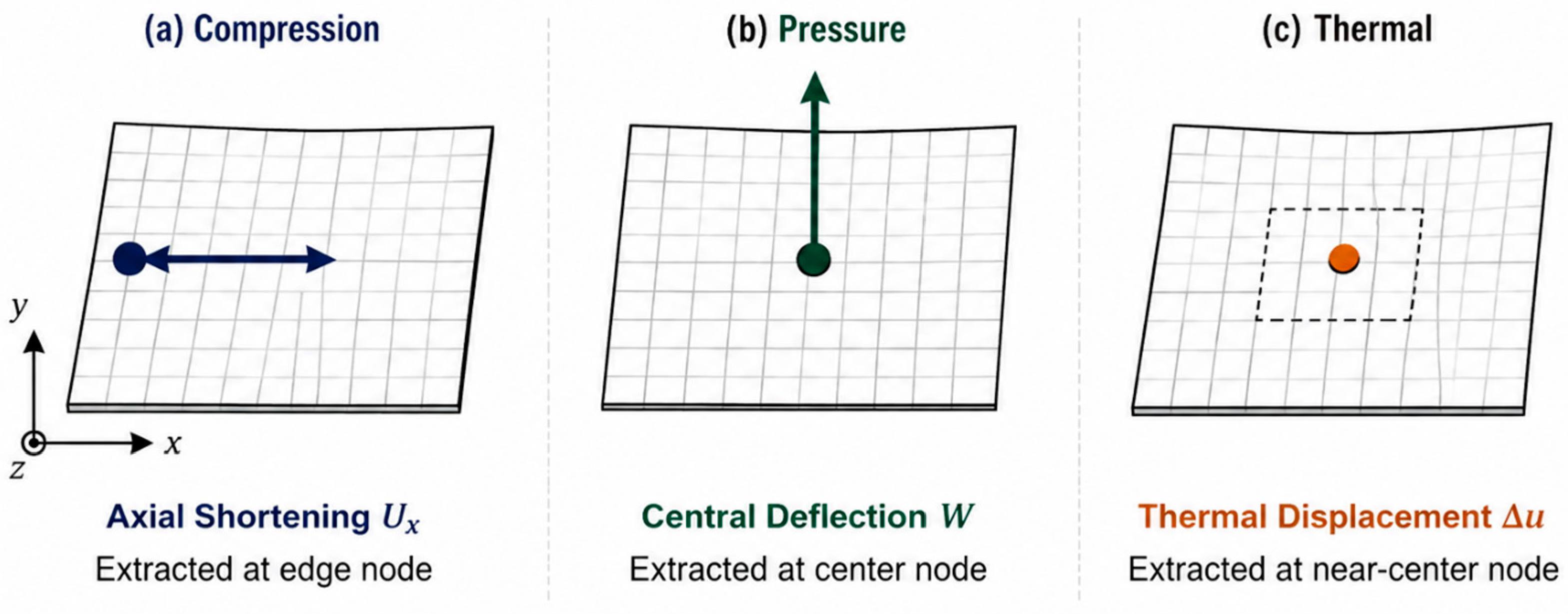
Three independent loading conditions were applied separately,
Figure 1:
In-plane compression ( N/mm);
Transverse pressure loading ( kPa);
Uniform thermal loading (
) [
12,
13].
The applied loads were selected to maintain linear structural response and are used comparatively rather than as representations of operational loading conditions. The present study intentionally focuses on stiffness-driven laminate behavior relevant to preliminary structural assessment before stability- and failure-driven design stages. The numerical workflow consisted of finite element analysis, displacement extraction, stiffness evaluation, normalization of stiffness metrics, and Pareto-based laminate assessment.
3. Stiffness Metrics and Pareto Framework
3.1. Displacement Extraction and Stiffness Evaluation
For each loading condition, a characteristic displacement quantity was defined according to the dominant deformation mechanism of the composite panel response. Under in-plane compression loading, stiffness evaluation was based on the average in-plane displacement along the loaded panel edge, avoiding the zero-displacement condition occurring near the panel center due to symmetry constraints. For transverse pressure loading, the response was characterized using the maximum out-of-plane displacement at the panel center, corresponding to bending-dominated plate behavior, as in [
12]. Thermal response was evaluated using displacement extracted from an unconstrained internal node in order to minimize boundary-condition influence on thermally induced deformation.
All stiffness metrics were computed using a load-to-displacement formulation, Equation (1):
where increased stiffness values correspond to reduced structural deformation under the applied loading condition.
The normalized stiffness indices used throughout the study were:
: normalized compression stiffness;
: normalized bending stiffness;
: normalized thermal stiffness metric.
Stiffness-based metrics were intentionally adopted instead of direct displacement ratios to maintain physically interpretable comparisons between laminate configurations.
3.2. Stiffness Anisotropy and Robustness Metrics
To interpret the directional stiffness characteristics of the investigated laminates, in-plane and bending stiffness anisotropy indices, Equations (2) and (3), were evaluated using the extensional and bending stiffness matrices of Classical Laminate Theory [
12]:
High anisotropy values indicate strong directional stiffness dependence and are generally associated with specialized laminate behavior, whereas reduced anisotropy corresponds to more distributed stiffness characteristics.
To evaluate laminate performance consistency across multiple loading conditions, a robustness index (
) was introduced, Equation (4):
Higher robustness values correspond to laminates exhibiting more uniform stiffness behavior across the examined loading scenarios, while lower values indicate highly specialized structural response. Thermal effects were incorporated within the robustness metric rather than treated as an independent Pareto objective, enabling unified multi-load evaluation without increasing visual complexity.
3.3. Pareto-Based Interpretation
The Pareto-based comparative interpretation was performed using the normalized compression and bending stiffness metrics (
and
) [
14,
15]. The resulting Pareto front was interpreted as a discrete laminate design space rather than a continuous optimization surface [
14,
15]. Consequently, no smoothing functions or regression-based approximations were introduced, allowing the physically meaningful discontinuities and slope changes associated with different laminate architectures to remain visible.
4. Results and Discussion
4.1. Normalized Stiffness Response
The normalized stiffness results revealed distinct laminate behaviors under the examined loading conditions, highlighting the strong influence of stacking-sequence architecture on structural performance. Significant differences were observed between laminates favoring in-plane load transfer and those exhibiting improved bending-dominated behavior.
The unidirectional [0]16 laminate exhibited the highest normalized compression stiffness () due to fiber alignment with the applied loading direction. However, the same configuration demonstrated comparatively low bending stiffness () under transverse pressure loading, indicating increased sensitivity to out-of-plane deformation.
In contrast, laminates containing transverse and angle-ply contributions exhibited more distributed stiffness behavior across the investigated loading conditions. The quasi-isotropic configuration demonstrated comparatively uniform response, although it did not maximize stiffness under any individual load case.
Hybrid laminates occupied intermediate positions between the compression-dominated and bending-dominated extremes. In particular, the [(0/90)4]s and [90/±45]s configurations provided a compromise by combining directional stiffness contributions from multiple ply orientations while reducing load-case specialization.
The observed stiffness trends highlight the importance of considering load sensitivity during preliminary laminate selection. Maximizing stiffness under a single loading condition may lead to reduced adaptability when multiple operational requirements are considered simultaneously. Failure, damage, and buckling phenomena were intentionally excluded to isolate stiffness-driven trends relevant to preliminary structural design assessment.
4.2. Pareto Front Interpretation
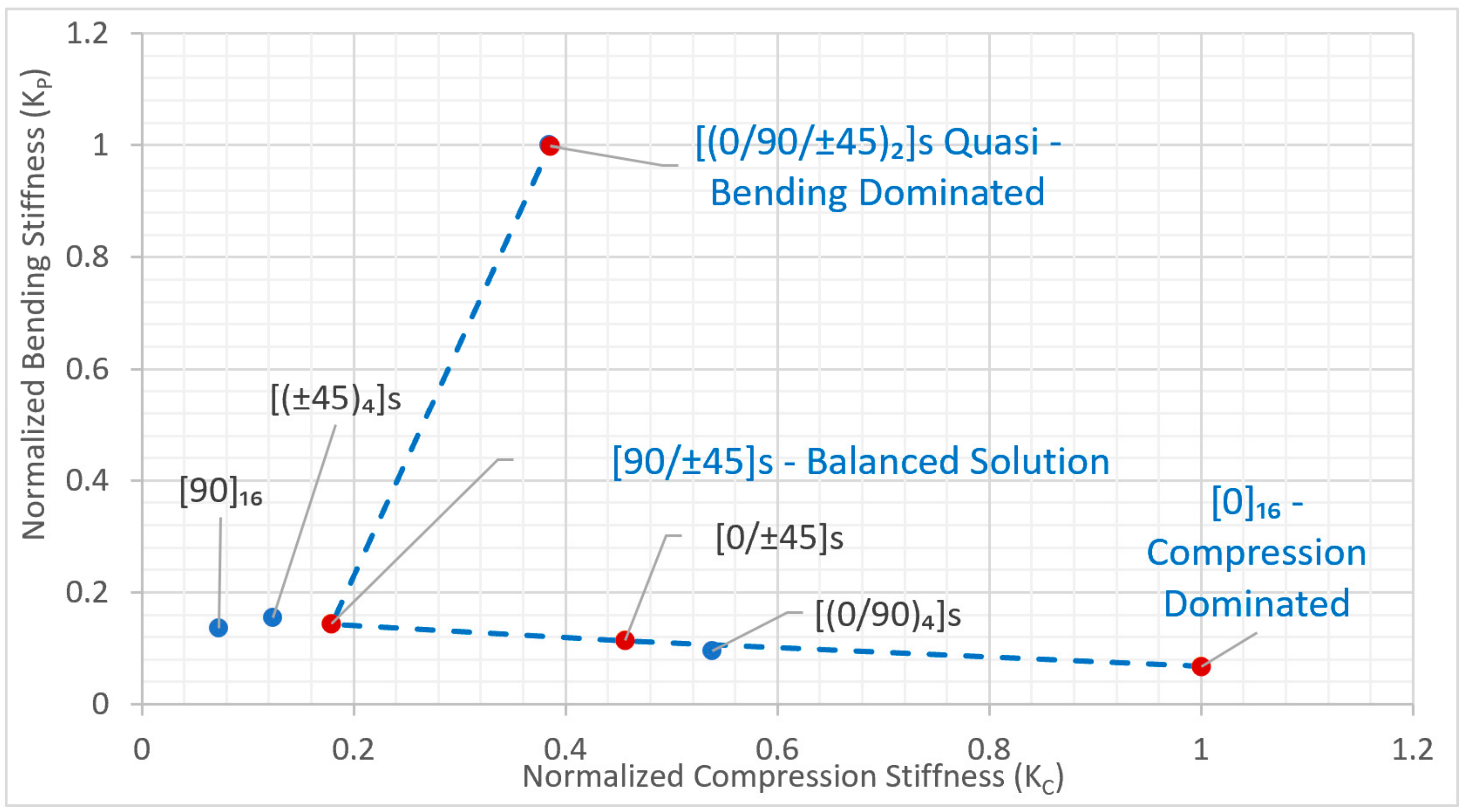
The Pareto-based comparative interpretation,
Figure 2, revealed a clear trade-off between compression stiffness (
) and bending stiffness (
), demonstrating that laminate performance is strongly dependent on the dominant loading environment. No laminate configuration simultaneously maximized both objectives, confirming the conflicting nature of membrane-dominated and bending-dominated structural requirements in composite panel design.
The resulting Pareto front exhibited a non-smooth and piecewise-linear character, reflecting the discrete nature of laminate stacking-sequence design rather than a continuous optimization space. The observed slope changes correspond to transitions between membrane-dominated and bending-dominated structural behavior.
The [0]16 laminate occupied the compression-dominated region of the design space, achieving high axial stiffness but limited bending adaptability. Conversely, laminates containing transverse and angle-ply contributions shifted toward improved bending response at the expense of membrane stiffness efficiency.
Hybrid laminates formed intermediate Pareto solutions between the two performance extremes. In particular, the [90/±45]s and [(0/90)4]s configurations demonstrated balanced stiffness characteristics suitable for structures subjected to competing loading demands. The quasi-isotropic laminate also occupied a balanced region of the Pareto space, although its response remained moderate rather than optimal for either individual objective.
The Pareto assessment further demonstrated that laminate selection should not rely solely on stiffness maximization under isolated loading conditions. Instead, stacking-sequence selection is governed by trade-offs between competing structural requirements. Laminates located away from the Pareto-optimal boundary were identified as dominated solutions with limited structural advantage compared with neighboring laminate configurations.
4.3. Stiffness Anisotropy and Robustness Assessment
The stiffness anisotropy indices were used to interpret the directional stiffness characteristics of the investigated laminates and explain their positioning within the Pareto design space. Laminates exhibiting high in-plane anisotropy generally demonstrated strong directional dependence under membrane loading, whereas reduced anisotropy corresponded to more distributed stiffness behavior and improved adaptability across competing loading conditions.
The [0]16 configuration, characterized by dominant axial stiffness along the fiber direction, occupied the compression-dominated region of the Pareto front and exhibited highly specialized behavior. In contrast, transverse and angle-ply contributions reduced stiffness imbalance and improved out-of-plane response under pressure loading. Highly anisotropic laminates therefore tended to occupy extreme regions of the design space, whereas hybrid and quasi-isotropic laminates shifted toward more balanced structural behavior.
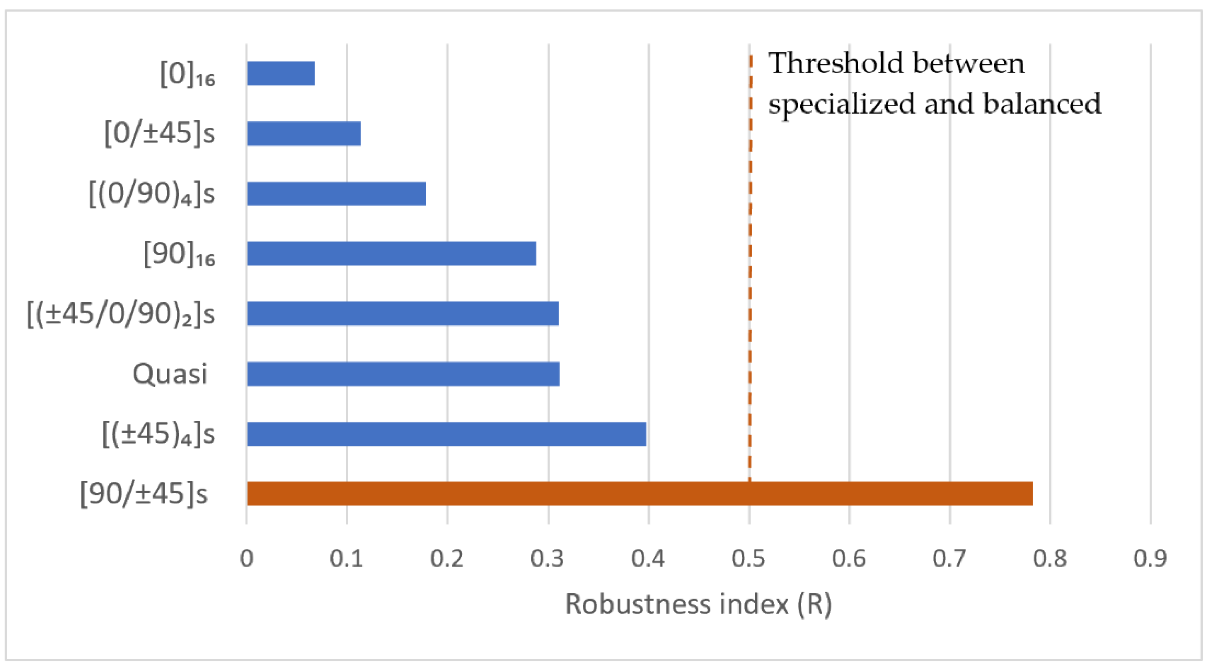
The robustness index (
) was additionally used to evaluate the ability of each laminate configuration to maintain consistent stiffness performance across the examined loading conditions,
Figure 3.
The results demonstrated that laminates optimized for a specific loading condition did not necessarily exhibit favorable overall performance. Despite its high compression stiffness, the [0]16 laminate produced relatively low robustness values due to its limited bending and thermal response balance. In contrast, hybrid laminates moderated stiffness extremes across competing load cases and demonstrated improved robustness characteristics.
Among the investigated configurations, the [90/±45]s laminate achieved the highest robustness index, indicating the most balanced overall response. The quasi-isotropic laminate also exhibited relatively balanced behavior, although its robustness remained lower than that of the best-performing hybrid configuration. These observations indicate that stiffness homogenization alone does not guarantee optimal multi-load structural performance.
Thermal effects were incorporated within the robustness metric rather than treated as an independent Pareto objective, enabling unified multi-load evaluation without increasing visual complexity. Although thermal response is not presented as an independent graphical dimension, its contribution is implicitly embedded within the robustness evaluation through the normalized thermal stiffness metric (
). This approach enables thermal effects to influence laminate ranking and balanced-response assessment without introducing additional visualization complexity within the Pareto interpretation framework. A compact summary of the normalized stiffness metrics, robustness values, and qualitative structural behavior classification is presented in
Table 1.
5. Conclusions
A design-oriented laminate assessment framework for composite aircraft panels was presented based on normalized stiffness metrics, Pareto-based comparative interpretation, stiffness anisotropy indices, and robustness evaluation under multiple loading conditions. The proposed methodology enables systematic comparison of laminate configurations subjected to competing structural demands relevant to preliminary aerospace structural design.
The results demonstrated that conflicting stiffness requirements are inherent to composite laminate behavior. No laminate configuration achieved optimal performance across all loading conditions, highlighting the importance of trade-off-driven laminate selection. Hybrid laminates exhibited improved adaptability across competing loading scenarios, whereas highly anisotropic laminates produced more specialized structural behavior.
The Pareto-based interpretation further demonstrated that laminate behavior evolves through discrete transitions rather than continuous performance variation, emphasizing the influence of stacking-sequence architecture on structural response characteristics. The anisotropy and robustness metrics provided physically interpretable indicators for evaluating laminate balance and load sensitivity.
The proposed framework is intended as a preliminary structural assessment tool rather than a high-fidelity certification methodology. Failure mechanisms, buckling response, geometric nonlinearities, and damage evolution were intentionally excluded to isolate stiffness-driven trends and maintain focus on laminate-level trade-offs.
Future work will extend the proposed methodology toward stiffened composite panel configurations, buckling-driven design constraints, and damage-tolerant aerospace structural applications.