Proceeding Paper

Multidisciplinary Design Optimisation of Flexible Aircraft: Advancing Aeroelastic Co-Design with Active Load Alleviation †
by
Armand-Ioan Curpanaru
1,2,3,*,
Philippe Pastor
1,2,
Fabrice Demourant
2,3 and
Eric Nguyen Van
2,3
1
Fédération ENAC ISAE-SUPAERO ONERA, Université de Toulouse, 31000 Toulouse, France
2
DCAS, ISAE-SUPAERO, 10 Avenue Marc Pélegrin, 31055 Toulouse, France
3
DTIS, ONERA, 2 Avenue Marc Pélegrin, 31400 Toulouse, France
*
Author to whom correspondence should be addressed.
Presented at the 15th EASN International Conference, Madrid, Spain, 14–17 October 2025.
Eng. Proc. 2026, 133(1), 108; https://doi.org/10.3390/engproc2026133108
Published: 9 May 2026

Abstract

The development of aircraft with high-aspect-ratio (HAR) wings and flexible lightweight structures is at the forefront of efforts for a more sustainable aviation. Nevertheless, this change in aircraft configuration is accompanied by significant complexity. Specifically, it calls for the modelling of strong aero-structural couplings and the concurrent synthesis of active control laws to mitigate the higher structural loads generated by HAR wings. Managing these challenges from the very onset of the preliminary design phase demands a unified approach. Consequently, this paper leverages a Flexible Wing Co-design framework that integrates aeroelastic wing design and robust H controller synthesis for gust load alleviation (GLA). This co-design capability is deployed to conduct a sensitivity analysis of wing aspect ratio effects, as well as a multidisciplinary design optimisation (MDO) approach focused on minimising mission block fuel. The results confirm that the proposed approach delivers substantial mass savings and superior aircraft performance, establishing it as an indispensable tool for the early stage development of next generation configurations.

1. Introduction

To meet aviation sustainability targets, high-aspect-ratio (HAR) cantilever wings and flexible structures have emerged as a primary focus for research and industry. This aircraft design enhances aerodynamic efficiency within the conventional tube-and-wing architecture, offering a lower-risk implementation pathway than radical topologies [1]. Furthermore, the expedited certification process for HAR configurations establishes them as a compelling near-term solution for reducing the sector’s carbon footprint [2,3,4,5].
However, HAR wings introduce strong aero-structural couplings and higher structural loads. Managing this complexity requires a unified design approach that integrates accurate aeroelastic modelling and the synthesis of active control laws for gust load alleviation.
This study leverages the Flexible Aircraft Co-design framework [6] to conduct a sensitivity analysis on the influence of wing Aspect Ratio (AR). The objectives are to quantify the impact of AR on structural mass and fuel consumption, establish aero-servo-elastic design trends, and evaluate the robustness of the integrated load alleviation controller. This methodology advances beyond standard analyses based on rigid [7] or static aeroelastic models [8] by explicitly incorporating active control synthesis, overcoming the limitations of studies restricted to passive alleviation [9].
Finally, the framework was deployed in an MDO workflow to minimise mission block fuel, using the wing AR as the design variable and the maximum wing root bending moment as an upper limit constraint. To isolate the benefits of the active control system, the optimisation was executed both with and without controller synthesis. Both gradient-free and gradient-based algorithms were utilised to cross-validate the results and ensure numerical consistency.

2. Methodology

Building upon the framework introduced in Ref. [6] by the authors, this study employs a multidisciplinary approach that couples overall aircraft design (OAD), aeroelastic modelling, and mixed structured H synthesis. The framework’s disciplinary coupling is illustrated in Figure 1a, while Figure 1b depicts the nested optimisation architecture.
For the OAD, FAST-OAD (Fixed-Wing Aircraft Sizing Tool) [10] serves as the basis of the sizing process. Developed by ISAE-SUPAERO and ONERA and based on the OpenMDAO [11] formalism, it is dedicated to preliminary aircraft design, analysis, and optimisation. It employs a point-mass approach and semi-empirical equations, considering key disciplines such as flight mechanics, aerodynamics, structures, and propulsion through a series of design loops. To overcome the limitations of FAST-OAD’s default semi-empirical and rigid-body formulations, the developed framework integrates the aeroelastic solver SHARPy (Simulation of high-aspect-ratio aeroplanes in Python, version 2.2) [12]. SHARPy is a medium-fidelity aeroelastic simulation tool that employs an Unsteady Vortex Lattice Method. Structurally, it utilises a displacement-based Geometrically Exact Beam Model, enabling the accurate representation of geometric nonlinearities.
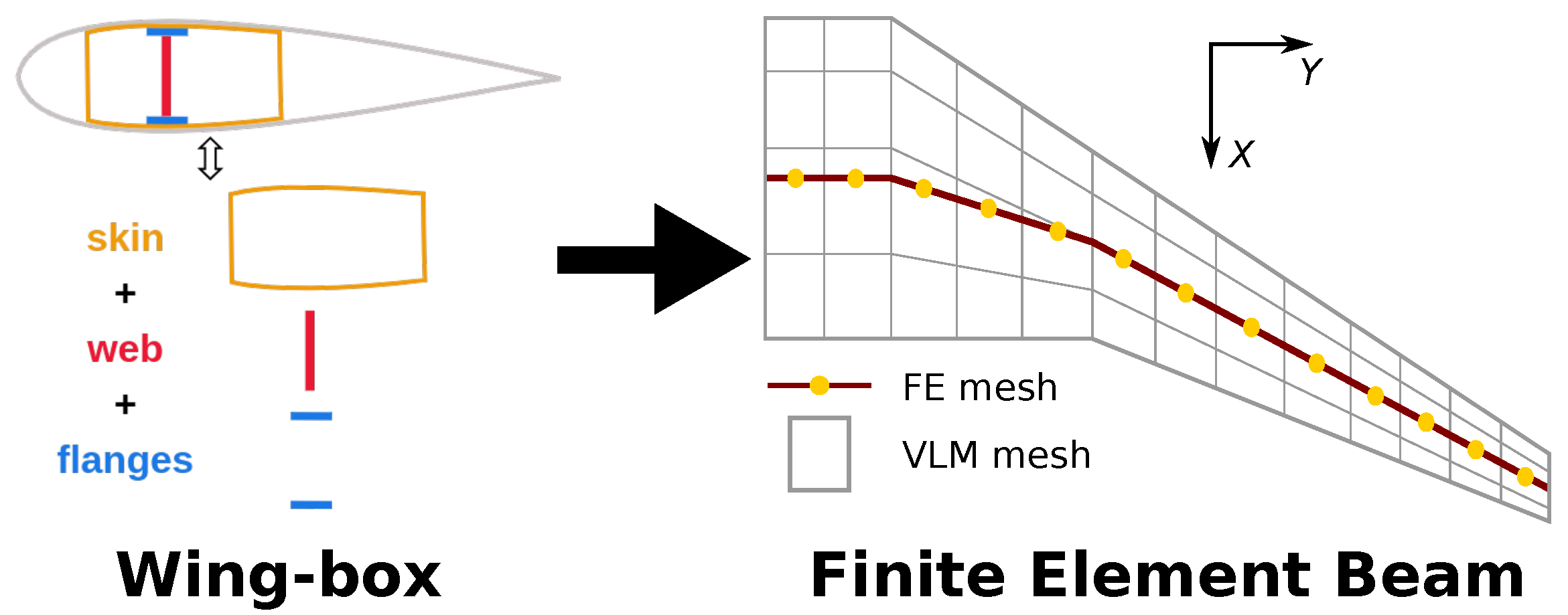
The coupling of the aeroelastic solver to the OAD framework required significant interface development to bridge the gap between the two structural models of the respective tools. To this end, a dedicated two-level structural sizing module was implemented within FAST-OAD, as shown in Figure 2. The first level comprises the FAST-OAD model: a simplified rectangular wing-box parameterised by the surfaces and thicknesses of its skins, webs, as well as upper and lower flanges. The second level constitutes the finite element beam model of the aeroelastic solver, defined by stiffness and mass matrices. Crucially, this module links the two levels by deriving the properties of the beam model directly from the characteristics of wing-box components. This approach guarantees the consistent and traceable generation of structural data. In parallel, the geometric data from FAST-OAD is converted to generate the lifting surfaces for the aeroelastic solver’s aerodynamic model.
The framework operates through two nested loops, as shown in Figure 1b. The outer loop, driven by the coupling of FAST-OAD and SHARPy, manages the OAD, including wing sizing and aeroelastic simulation. At each iteration, the MDA cycle entails the generation, linearisation, and reduction of the nonlinear aeroelastic wing model to produce a reduced order model. This model is sent to the inner loop to synthesise a robust H controller for load alleviation. Afterwards, the resulting structure and gains of the controller are sent to the outer loop. The GLA controller is then coupled with the full nonlinear aeroelastic model for conducting dynamic simulations. This software-in-the-loop approach also serves to validate the control law. The data from the closed-loop dynamic simulations is post-processed to extract critical loads, which subsequently drive the structural resizing.
The synthesis of the active load alleviation system is performed using the H robust control method. The standard H formulation is depicted in Figure 3a, which highlights the feedback interconnection between the augmented plant P and the controller K. The augmented plant P encapsulates the linearised aeroelastic wing model dynamics and the weighting functions applied to the transfers between exogenous inputs w and exogenous outputs z. For the control scheme, the strategy relies on a single measured output y, namely the wing tip vertical acceleration ( W T A z ). This signal is fed to the controller K, which computes the corresponding control input u required to actuate the wing tip aileron.
The exogenous inputs w characterise external disturbances, such as atmospheric perturbations (gusts and turbulence) or sensor/actuator noise, and the exogenous outputs z are performance signals to be controlled. The fundamental principle of H synthesis lies in the systematic formulation of specific transfer functions between w and z that capture the control objectives. The synthesis process seeks to minimise or bound the H norm of these transfer functions, formulating the minimisation objectives as soft constraints and the strict bounding requirements as hard constraints. As defined in Equation (1), the H norm corresponds to the system’s peak gain across the frequency domain.
As the primary objective is to actively mitigate structural loads induced by atmospheric gust perturbations ( w g u s t ), the synthesis problem is formulated to minimise the H norm of the transfers targeting the Wing Root Bending Moment ( w g u s t z W R M y ) and the Wing Tip Vertical Displacement ( w g u s t z W T D z ). Concurrently, constraints are imposed on specific transfer functions: the transfer from the reference to the error ( w r z ϵ ) to ensure adequate robustness margins; the transfer from the input disturbance to the measured output ( w d z W T A z ) to provide disturbance rejection; the transfer from the reference to the control input ( w r z u ) to limit the actuator effort. Consequently, the resulting controllers achieve robust performance against unmodelled dynamics and uncertainties. This robustness is critical, ensuring that control laws synthesised on the linear reduced order model remain effective when deployed on the full nonlinear aeroelastic model. The complete synthesis scheme is illustrated in Figure 3b, with further details in Ref. [6].
H ( s ) = m a x ω R | H ( j ω ) |

3. Results

3.1. Parametric Study on the Effect of Wing Aspect Ratio

This study conducts a parametric sensitivity analysis of the wing Aspect Ratio (AR), employing input data representative of the ATR72 Top-Level Aircraft Requirements. Structural sizing is driven by a critical dynamic aeroelastic load case, initialised at steady-state 1g cruise. The simulation incorporates a 1-cosine discrete gust (length 96 m , amplitude 11 m / s ), calculated in compliance with CS-25 Regulation for Large Aeroplanes, available at: https://www.easa.europa.eu/en/document-library/certification-specifications/group/cs-25-large-aeroplanes, accessed on 3 April 2025.
The results are summarised in Figure 4. The results in Figure 4a,b show that, while wing root bending moment increases with AR, the rate diminishes at higher aspect ratios due to passive load alleviation induced by structural flexibility. The shear force distribution remains largely linear, with a distinct discontinuity caused by the engine mass and a slight reduction in root shear as AR increases. Finally, the comparison between baseline (solid line, No GLA) and active control cases (dashed line, With GLA) in Figure 4c,d confirms the effectiveness of the GLA law in mitigating gust-induced dynamic loads.
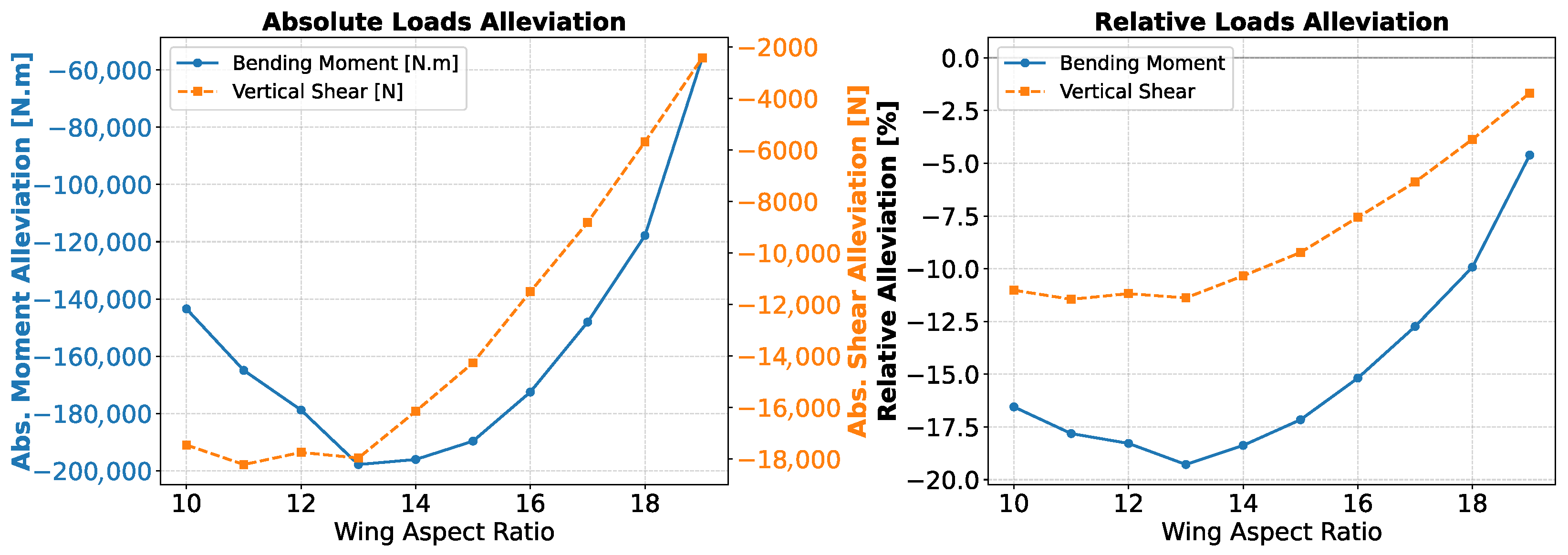
The absolute and relative reductions of the structural loads as a function of aspect ratio are shown in Figure 5. These values are derived from the converged MDA runs, comparing the configurations with and without the active GLA control law. At an AR = 10, the system achieves a relative load reduction of approximately 16 % for bending moment and 11 % for shear force. The reduction improves with increasing AR, peaking at around 19 % for the bending moment for an A R = 13 . However, at higher AR values, the trend reverses sharply, with the relative reduction dropping to approximately 4 % in bending moment and 2 % in shear force for an A R = 19 . The causes of these distinct trends are explained in the following paragraphs.
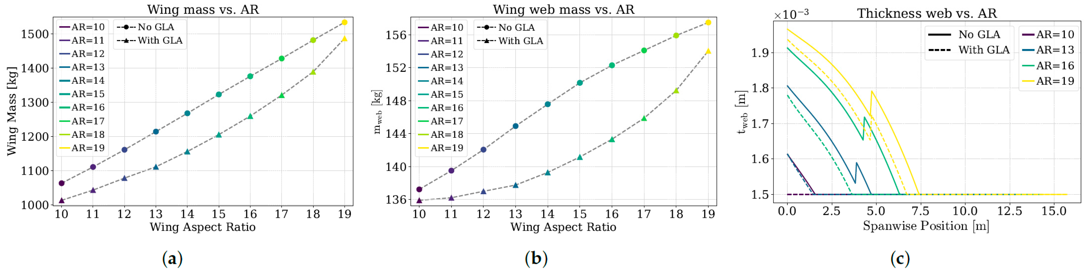
In terms of wing mass, the No-GLA configurations () exhibit a nearly linear increase with AR, Figure 6a. In contrast, the GLA configurations () show a clear reduction in structural mass, directly reflecting the lower sizing loads achieved. This trend is further analysed in Figure 6b via the mass of the wing-box webs. The results show that the mass saving is modest at low AR values, increases significantly at medium AR values, and diminishes again at high AR values. The limited benefit at low AR is attributed to minimum gauge constraints. As shown in Figure 6c, sizing at A R = 10 is dominated by minimum technological thickness limits rather than load requirements. Consequently, load alleviation in this regime cannot translate into significant thickness reductions, capping the achievable mass savings.
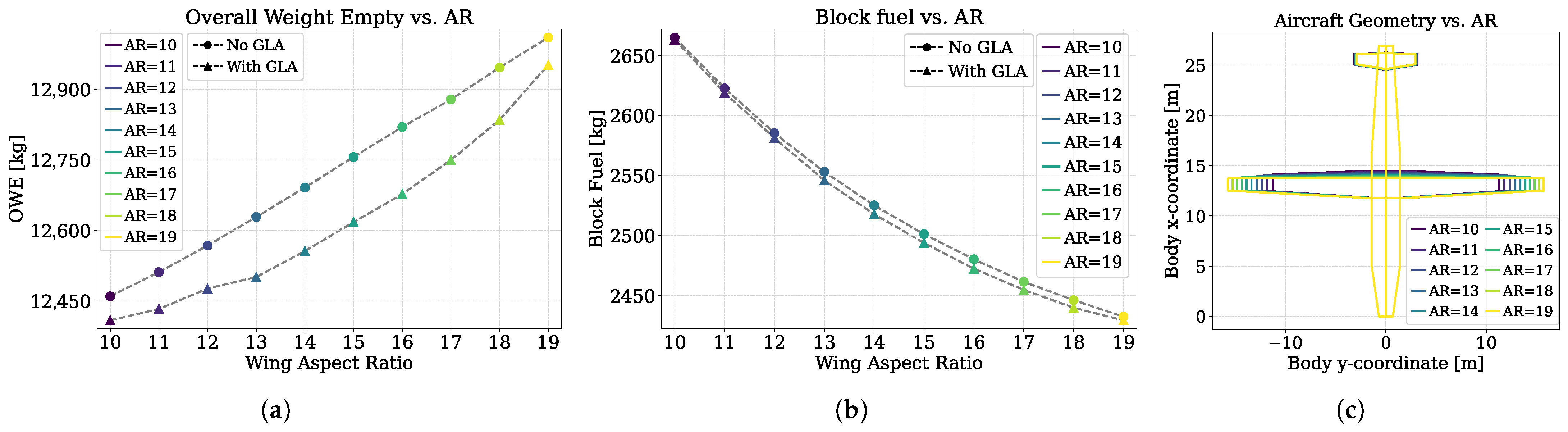
The reductions in structural wing mass propagate directly to the global aircraft metrics. Figure 7a shows the Operating Empty Weight (OEW) mirroring wing mass trends: the baseline rises linearly with AR, while the GLA configuration achieves a distinct reduction. For block fuel shown in Figure 7b, the GLA impact is marginal at fixed AR. The dominant driver here is aerodynamic: higher aspect ratios reduce induced drag, causing a decrease in the mission block fuel consumption. Finally, Figure 7c illustrates the wing planform evolution, highlighting a slight reduction in horizontal tail area as AR increases.
Table 1 compares the MDA results with and without GLA for a wing AR = 14. The data show that mitigating structural loads yields an 8.84 % reduction in wing mass, cascading into a 0.64 % ( 135 kg ) lower OEW and a 0.32 % decrease in block fuel, while wing span and area are slightly reduced, the maximum lift-to-drag ratio ( L / D max ) remains effectively constant. Furthermore, the static margin for both configurations remains around 6.4 % , well above the 5 % minimum stability target set in the MDA. This confirms that the significant mass reductions were achieved without compromising handling qualities or resulting in excessive stability that would degrade manoeuvrability.
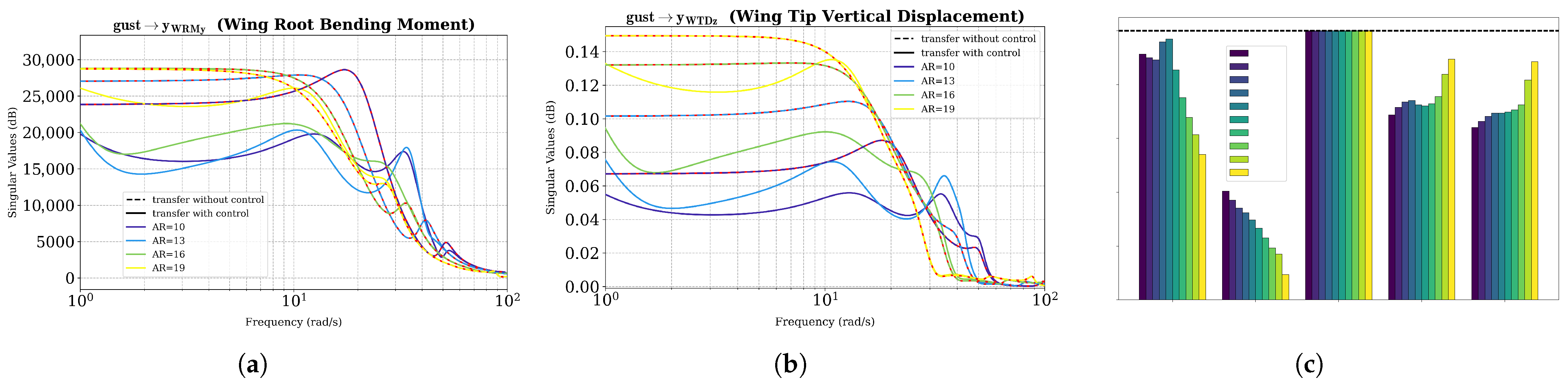
To explain the load alleviation performance drop at high AR, the GLA controller synthesis metrics are analysed. Figure 8a,b display the minimisation targets, namely the transfer functions from gust input w gust to performance outputs z WRMy and z WTDz . Comparing uncontrolled (– –) and controlled () responses reveals that the gap between their H norms narrows with increasing AR, indicating saturation in the controller’s attenuation capability. For clarity, uncontrolled responses use AR-dependent colour coding with alternating red dashed segments. Figure 8c quantifies this by plotting synthesis constraint values (ratio of controlled to uncontrolled H norms) against AR; while hard constraints on w r z ϵ , w d z W T A z and w r z u remain below unity, the soft constraints on w g u s t z W R M y and w g u s t z W T D z approach 1 as AR increases. This saturation explains the diminishing mass savings. The underlying mechanisms are complex and likely stem from shifts in aeroelastic dynamics, modal constraints on controller and pole placement, or reduced control surface effectiveness. Detailed investigation is beyond the scope of this study and left for future work.

3.2. Multidisciplinary Design Optimisation

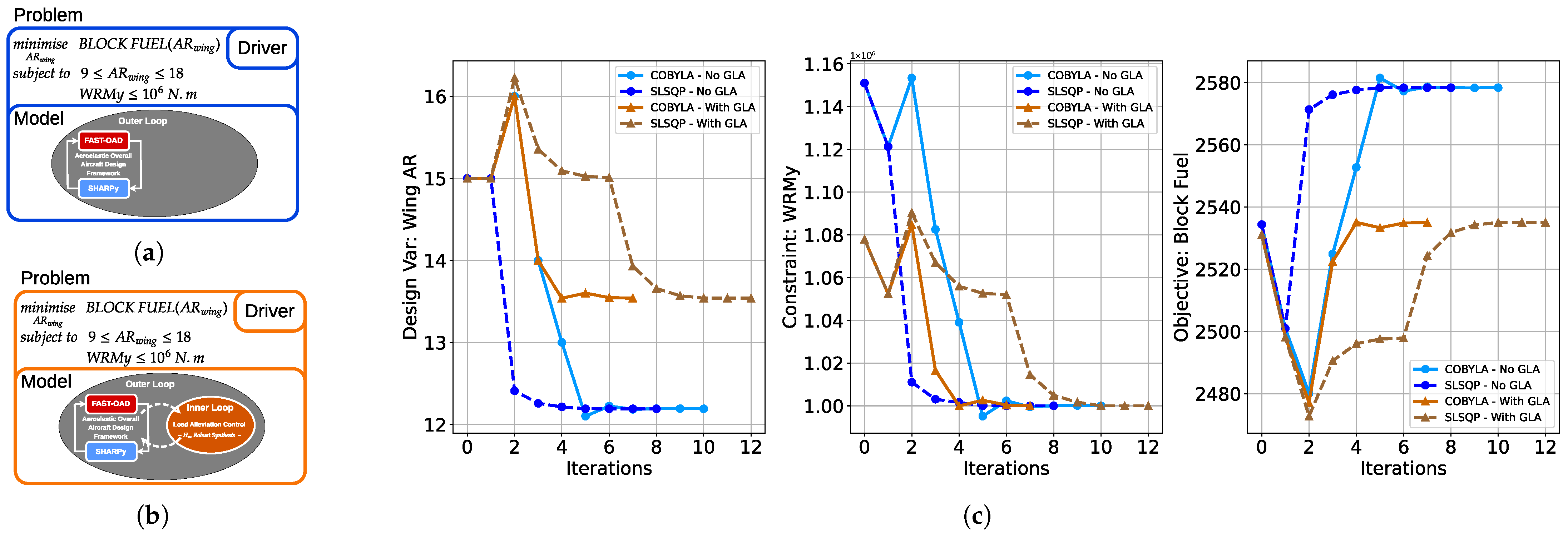
This section details the MDO study results. To demonstrate the capabilities of the framework, an optimisation problem was formulated (Equation (2)) with the objective of minimising mission block fuel. The wing AR is set as a design variable, subject to bounds and a constraint on the maximum wing root bending moment (WRMy) is included. Two configurations were evaluated: a baseline without control (Figure 9a) and a fully integrated GLA configuration (Figure 9b). The MDA design loops were solved using a Nonlinear Block Gauss–Seidel solver [13], while the optimisation driver utilised both gradient-based (SLSQP [14]) and gradient-free (COBYLA [15]) algorithms.
minimise A R w i n g B L O C K F U E L ( A R w i n g ) subject to 10 A R w i n g 19 W R M y 10 6 N . m
Figure 9c presents the optimisation results. Crucially, both gradient-based (– –) and gradient-free () algorithms converged to identical optima for the baseline () and GLA-integrated () configurations. This numerical stability is crucial, especially given that the GLA-integrated configuration involves two distinct optimisation layers: an inner-loop solver for controller synthesis and a global driver for the MDO problem. In all cases, the root bending moment constraint was respected. Notably, the GLA system enables an increase in optimal AR from 12.2 to 13.5, resulting in a 40 kg fuel reduction via improved aerodynamic efficiency. These results confirm the framework’s capability to solve aero-servo-elastic MDO problems.

4. Conclusions

Through parametric sensitivity analysis, this study established key aeroelastic design trends and demonstrated the robustness of the proposed framework across a wide aspect ratio range. The subsequent application to an MDO problem confirmed the framework’s capability to handle complex couplings and highlighted the effectiveness of the GLA controller in alleviating structural loads. Ultimately, this work confirms that the Flexible Wing Co-design framework serves as a vital aero-servo-elastic design tool, integrating controller synthesis for load alleviation directly into the preliminary design phase.

Author Contributions

Conceptualisation, A.-I.C., P.P., F.D. and E.N.V.; methodology, A.-I.C., P.P., F.D. and E.N.V.; software, A.-I.C.; validation, A.-I.C.; formal analysis, A.-I.C.; investigation, A.-I.C.; resources, E.N.V.; data curation, A.-I.C.; writing—original draft preparation, A.-I.C.; writing—review and editing, P.P., F.D. and E.N.V.; visualization, A.-I.C.; supervision, P.P., F.D. and E.N.V.; project administration, P.P., F.D. and E.N.V.; funding acquisition, P.P. All authors have read and agreed to the published version of the manuscript.

Funding

This research was funded by Fédération ONERA ISAE-SUPAERO ENAC (FONISEN).

Institutional Review Board Statement

Not applicable.

Informed Consent Statement

Not applicable.

Data Availability Statement

The data presented in this study are available on request from the corresponding author upon reasonable request.

Conflicts of Interest

The authors declare no conflicts of interest.

References

  1. Farsadi, T.; Ahmadi, M.; Sahin, M.; Haddad Khodaparast, H.; Kayran, A.; Friswell, M.I. High Aspect Ratio Composite Wings: Geometrically Nonlinear Aeroelasticity, Multi-Disciplinary Design Optimization, Manufacturing, and Experimental Testing. Aerospace 2024, 11, 193. [Google Scholar] [CrossRef] [Scilit]
  2. Ma, Y.; Elham, A. Designing high aspect ratio wings: A review of concepts and approaches. Prog. Aerosp. Sci. 2024, 145, 100983. [Google Scholar] [CrossRef] [Scilit]
  3. Le Lamer, Y.; Morlier, J.; Bénard, E.; He, P. Aeroelastic Analysis and Optimization of High Aspect Ratio and Strut-Braced Wings. In Proceedings of the Thematic Conference on Multidisciplinary Design Optimization of Aerospace Systems (AEROBEST), Lisbon, Portugal, 19–21 July 2023. [Google Scholar]
  4. Wunderlich, T.F. Optimal Wing Aspect Ratio of Highly Efficient Long-Range Aircraft. In Proceedings of the 34th Congress of the International Council of the Aeronautical Sciences (ICAS 2024), Florence, Italy, 9–13 September 2024. [Google Scholar]
  5. Pacheco, L.M.M. Optimisation of a High Aspect-Ratio Transport Wing Using Coupled High-Fidelity Methods. Master’s Thesis, Universidade de Lisboa, Lisbon, Portugal, 2025. [Google Scholar]
  6. Curpanaru, A.I.; Pastor, P.; Demourant, F.; Nguyen-Van, E. Flexible Wing Co-Design Through MDA and Active Control for Load Alleviation. In Proceedings of the AIAA Aviation Forum and Ascend 2025, Las Vegas, NV, USA, 21–25 July 2025. [Google Scholar] [CrossRef] [Scilit]
  7. Carrier, G.; Arnoult, G.; Fabbiane, N.; Schotte, J.S.; David, C.; Defoort, S.; Benard, E.; Delavenne, M. Multidisciplinary analysis and design of strut-braced wing concept for medium range aircraft. In Proceedings of the AIAA SCITECH 2022 Forum, San Diego, CA, USA & Virtual, 3–7 January 2022. [Google Scholar] [CrossRef] [Scilit]
  8. Kilimtzidis, S.; Kostopoulos, V. Static Aeroelastic Optimization of High-Aspect-Ratio Composite Aircraft Wings via Surrogate Modeling. Aerospace 2023, 10, 251. [Google Scholar] [CrossRef] [Scilit]
  9. Sinha, K.; Klimmek, T.; Schulze, M.; Handojo, V. Loads analysis and structural optimization of a high aspect ratio, composite wing aircraft. CEAS Aeronaut. J. 2021, 12, 233–243. [Google Scholar] [CrossRef] [Scilit]
  10. David, C.; Delbecq, S.; Defoort, S.; Schmollgruber, P.; Benard, E.; Pommier-Budinger, V. From FAST to FAST-OAD: An open source framework for rapid Overall Aircraft Design. IOP Conf. Ser. Mater. Sci. Eng. 2021, 1024, 012062. [Google Scholar] [CrossRef] [Scilit]
  11. Gray, J.S.; Hwang, J.T.; Martins, J.R.R.A.; Moore, K.T.; Naylor, B.A. OpenMDAO: An open-source framework for multidisciplinary design, analysis, and optimization. Struct. Multidiscip. Optim. 2019, 59, 1075–1104. [Google Scholar] [CrossRef] [Scilit]
  12. del Carre, A.; Muñoz-Simón, A.; Goizueta, N.; Palacios, R. SHARPy: A dynamic aeroelastic simulation toolbox for very flexible aircraft and wind turbines. J. Open Source Softw. 2019, 4, 1885. [Google Scholar] [CrossRef] [Scilit]
  13. Grippo, L.; Sciandrone, M. On the convergence of the block nonlinear Gauss–Seidel method under convex constraints. Oper. Res. Lett. 2000, 26, 127–136. [Google Scholar] [CrossRef] [Scilit]
  14. Kraft, D. A Software Package for Sequential Quadratic Programming; Technical Report DFVLR-FB 88–28; German Aerospace Center (DLR): Cologne, Germany, 1988. [Google Scholar]
  15. Powell, M.J.D. A Direct Search Optimization Method That Models the Objective and Constraint Functions by Linear Interpolation. In Advances in Optimization and Numerical Analysis; Springer: Dordrecht, The Netherlands, 1994; pp. 51–67. [Google Scholar] [CrossRef] [Scilit]
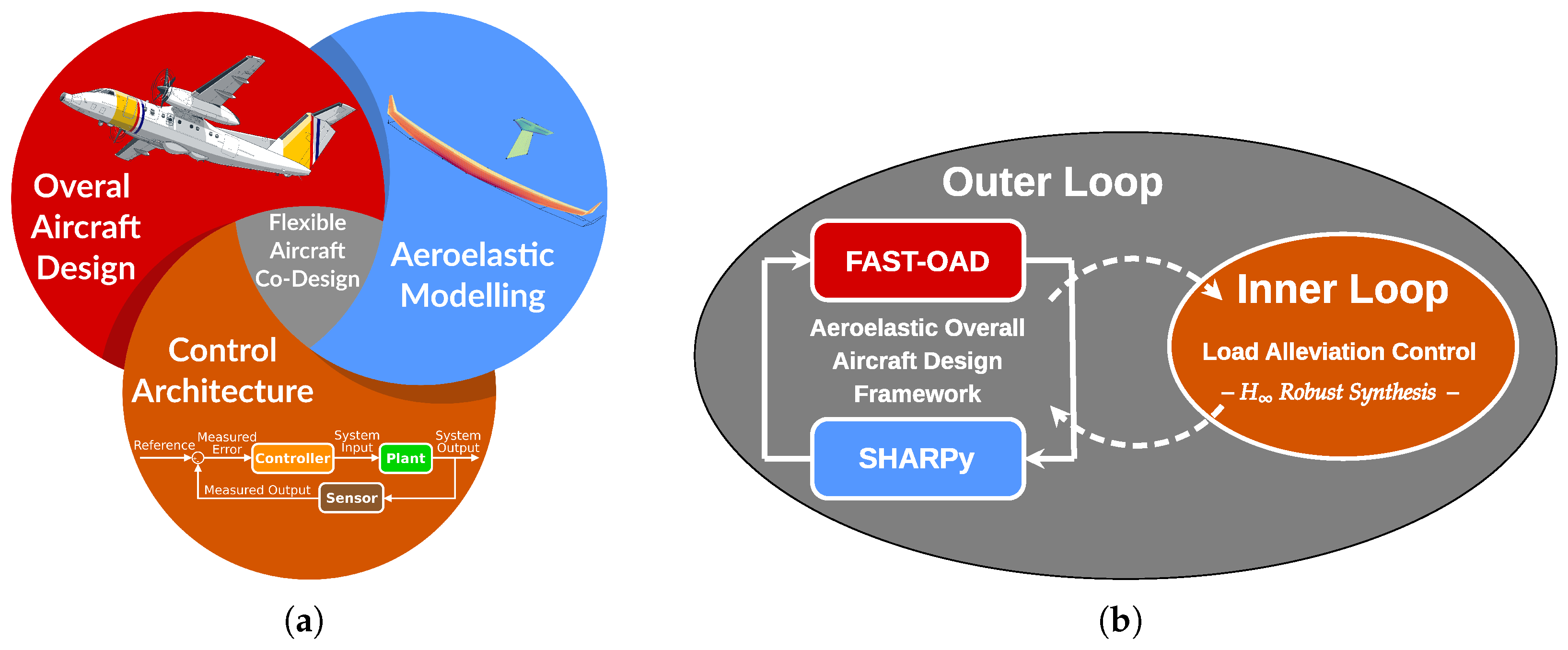
Figure 1. (a) Diagram of the coupled aero-servo-elastic aircraft design framework. (b) Schematic of the nested optimisation framework.
Engproc 133 00108 g001
Figure 2. Two-level wing structural model.
Engproc 133 00108 g002
Figure 3. (a) Standard form of H problem (b) Synthesis architecture for the GLA controller [6].
Engproc 133 00108 g003
Figure 4. (a) Bending moment M y vs. AR (No GLA); (b) Shear force F z vs. AR (No GLA); (c) Bending moment M y vs. AR (with and without GLA); (d) Shear force F z vs. AR (with and without GLA).
Engproc 133 00108 g004
Figure 5. Absolute and relative alleviation of wing structural loads achieved by the GLA control law.
Engproc 133 00108 g005
Figure 6. (a) Wing structural mass vs. AR; (b) Wing web mass vs. AR; (c) Spanwise distribution of web thickness vs. AR.
Engproc 133 00108 g006
Figure 7. (a) Overall Weight Empty vs. AR; (b) Block Fuel vs. AR; (c) Aircraft Geometry vs. AR.
Engproc 133 00108 g007
Figure 8. (a) g u s t y W R M y transfer with and without GLA controller; (b) g u s t y W R D z transfer with and without GLA controller; (c) Values of the hard and soft synthesis constraints.
Engproc 133 00108 g008
Figure 9. (a,b) Baseline and co-design architectures; (c) Optimisation history.
Engproc 133 00108 g009
Table 1. MDA results for wing AR = 14 with and without GLA controller synthesis.
Wing AR = 14Aeroelastic
MDA
Aeroelastic
MDA with GLA
Absolute
Change
Relative
Change
Wing Mass [kg]12671155−112−8.84%
OWE [kg]12,69112,556−135−1.06%
Block Fuel [kg]25252517−8−0.32%
Wing Span [m]26.7726.67−0.10−0.37%
Wing Area [m2]51.1750.83−0.34−0.66%
L/D (max)18.1518.11−0.04−0.22%
Static Margin [%]6.47776.4009 7.68 · 10 3 −1.18%
Disclaimer/Publisher’s Note: The statements, opinions and data contained in all publications are solely those of the individual author(s) and contributor(s) and not of MDPI and/or the editor(s). MDPI and/or the editor(s) disclaim responsibility for any injury to people or property resulting from any ideas, methods, instructions or products referred to in the content.