Proceeding Paper

Flight Tests of Scaled Demonstrator for General Aviation Aircraft Concept †
1
Institute of Electrified Aero Engines, German Aerospace Center (DLR), Carlo-Schmid-Straße 12, 52146 Würselen, Germany
2
Institute of Electrified Aero Engines, German Aerospace Center (DLR), Lieberoser Straße 13a, 03046 Cottbus, Germany
*
Author to whom correspondence should be addressed.
Presented at the 15th EASN International Conference, Madrid, Spain, 14–17 October 2025.
Eng. Proc. 2026, 133(1), 106; https://doi.org/10.3390/engproc2026133106
Published: 9 May 2026

Abstract

The present work investigates the flight characteristics and handling qualities of the novel aircraft concept “HyBird” through multiple scaled flight experiments. Various adaptations were made to the demonstrator—especially to the placement of the electrically driven propeller. The first flight experiment revealed drawbacks of the positioning of the electric propeller at the wing tips and tips of the V-Tail. In further experiments, the propeller positioning was changed to investigate a modified aircraft configuration. These flight tests showed significantly improved flight characteristics. The findings substantiate the critical role of propeller positioning in the design of novel aircraft concepts.

1. Introduction

The EU set ambitious goals for the future aviation sector throughout the Flightpath 2050 document: CO2 emission reduction by 75%, NOx emission reduction by 90% and noise reduction by 65% [1]. Additionally, the Air Transport Action Group (ATAG) displays traffic forecasts, technology developments and improvements in the operation and handling of transport aircraft [2]. For various scenarios ATAG shows projections for the CO2 emissions in the upcoming years until 2050. Even with the most ambitious technology changes and improvements in aircraft operations, there is still a gap to reach net-zero CO2 emissions in 2050. New, unconventional aircraft concepts may become relevant as well as new powertrain concepts.
One example of increasing interest in recent years is the distribution of propulsive power at the wing (DEP) [3]. It can bring benefits with respect to low-speed aerodynamic performance, as well as new possibilities regarding redundancy and novel handling strategies. This concept requires an unconventional engine placement on the aircraft, often with propulsors located near the wing tips. Many studies have been conducted focusing on the structural and aerodynamic characteristics of a DEP concept on various aircraft applications [4,5,6,7]. But significant research is still necessary into DEP concepts in flight experiments, especially regarding the effects of the unconventional propulsor placement.
The DLR project Future General Aviation Aircraft (FGAA) focused on the development of a nine-seater aircraft within the Certification Specifications 23 (CS-23) [8]. An initial starting point in the project was the HyBird concept [9], with electrically driven propellers at the wing tips and tips of the V-Tail. The engines will be provided from a battery system in the wings and from two turbines and generators located in the nose of the aircraft. Four propellers are placed at the tips of the wing and at the tips of the V-Tail to reduce the induced drag and increase flight performance. Figure 1 displays a rendering of the aircraft concept and in Table 1 the overall parameters of the aircraft concept are shown.
In the first step the main top-level aircraft requirements were defined in [10], followed by the design and evaluation of several aircraft concepts [11]. This evaluation also included a DEP concept. Different powertrain topologies for the application were compared in [12], as a serial hybrid electric seems to be the most promising option.
In recent years Unmanned Aircraft Systems (UASs) became more relevant for aviation research due to significant cost reduction for smaller-scale mechatronics and communication systems as well as lower prices for rapid prototyping and manufacturing [13]. UASs can be used for the development and testing of new aircraft concepts or new technologies. With different approaches during the design of a scaled model, a lot of research fields can be assessed with scaled experiments.
In the presented study the HyBird aircraft concept was investigated within scaled flight experiments. The method of scaled flight testing was chosen to conduct flight experiments with unconventional aircraft concepts, at comparable low costs. In particular, the effects of the unconventional propeller placement on the flight characteristics and handling qualities were assessed. Different configurations of the scaled UAS are investigated and compared between each other. These data can be beneficial for the design process of future aircraft concepts with similar unconventional propeller placements. However, these scaled flight experiments cannot substitute full-scale experiments to fully assess the effects of unconventional propulsor placements.

2. Methods

2.1. Scaled Flight Testing

Scaled flight testing means experiments with untethered, free flying, scaled models [14]. Flight experiments with scaled models can collect information about a larger vehicle, a more complex system or a specific technology. They can be applied during an aircraft design process to evaluate characteristics of a new aircraft concept before building a full-scale prototype. Experimental testing of new aircraft concepts and sub-components is cost-intensive, but is still mandatory during design and especially for certification. Full-scale experiments are often limited by sub-system or component tests, as extensive efforts would be necessary to conduct full-scale experiments. Scaled flight testing enables an option to deliver qualitative data in the early stages of the aircraft design process with lower costs and risks. Scaling laws for free flying models have been presented in the literature extensively [14,15,16]. In order to ensure comparability between the subscale model and the full-scale concept during the experiments, specific similarities have to be matched. The most common ones are the Reynolds number, the Mach number and the Froude number. In a best-case scenario, all similarities should be matched between the subscale model and the full-scale concept. In reality, it is almost impossible to ensure all similarities shown by the calculation in [17]. As not all parameters of the full-scale concept may be known at the beginning, it is possible to satisfy a limited number of scaling laws. Possible scaling approaches were summarized by [14,18]. In the presented project a demonstrative approach was applied for the design of the vehicle, with the main purpose to demonstrate the flight of the aircraft concept and to assess the characteristics of an unconventional propeller placing in an aircraft concept. In particular, the influence of the propeller placing on the flight characteristics and the handling qualities were analyzed. Different measures were tested during campaigns to improve the flight characteristics of the demonstrator.

2.2. Vehicle Description

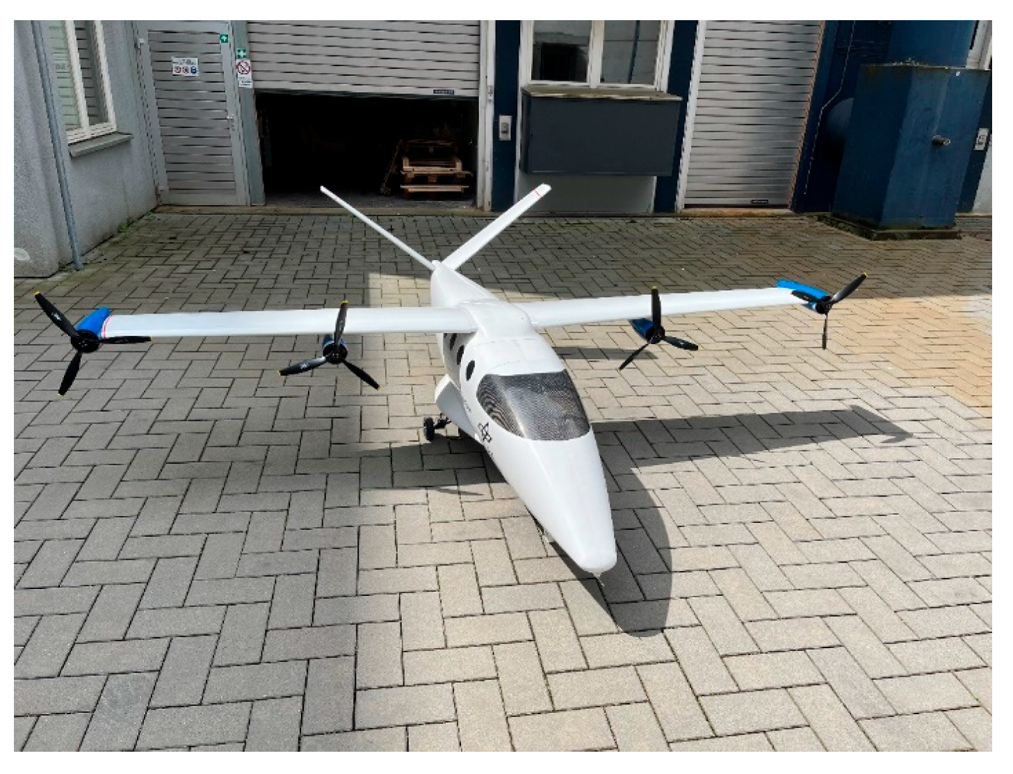
According to certification regulations in the EU for operations in the open category [19], a maximum take-off mass of 25 kg was defined for the scaled UAS. The scaled design for flight testing has a scaling factor of 0.25 and is geometrically scaled with a demonstrative scaling approach. This means most of the geometric dimensions were scaled according to the scaling factor. The overall parameters of the UAS are displayed in Table 2. Because a demonstrative scaling approach is applied, no aerodynamic, dynamic or aeroelastic scaling was considered. The wing profiles and the empennage profiles were changed to enhance the flight behavior for smaller-velocity regimes. To simplify the manufacturing process of the UAS, fixed landing gear instead of the original retractable landing gear was selected. The fuselage of the UAS was built from a composite sandwich construction with a 3 mm honeycomb core. The wing and empennage were build based on a styro-abbachi construction. Figure 2 displays the fully assembled HyBird demonstrator before maiden flight.
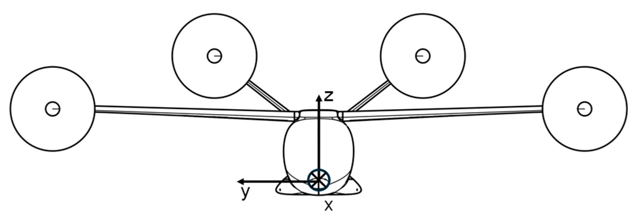
The coordinate system applied for all calculations and used to display all results in this study is displayed in Figure 3.
In contrast to the full-scale HyBird concept, the scaled UAS was built with an all-electric battery-based powertrain. A XTRON 12S lithium–polymer battery with 16,000 mAh (StefansLipoShop GmbH, Althegnenberg, Germany) was integrated as the primary energy source for the four U8 II 100 kv electric brushless motors (T-MOTOR, Nanchang, China). Each motor was controlled by one Alpha 60 A HV V1.2 FOC electronic speed controller (ESC) (T-MOTOR, Nanchang, China). For actuation of all control surfaces and the nose-wheel steering, seven Savöx SB-2270SG+ high-voltage servos (JSP GROUP INTL BV, Olen, Belgium) were applied. The pilot input was transferred with a redundant DC-24 II 2.4 GHz radio system (JETI model s.r.o., Pribor, Czech Republic) to two receivers in the UAS. These inputs were given to an autopilot system using the open source software ArduPlane in version 4.3.0 [20]. The Cube Orange flight controller (CubePilot Global Pty Ltd., Norlane, VIC, Australia) calculates the necessary input signals for all servos and motor controllers. The UAS can be operated in different control modes. In manual mode, the pilot directly commands angular rates for all axises with no stabilization from the autopilot. In stabilization mode the pilot commands angular deflections and the autopilot stabilizes the UAS to compensate for any disturbance. In addition, the UAS can be operated in an autonomous way, where specific geographic locations are loaded onto the autopilot as waypoints and the autopilot guides the UAS through the waypoint mission. All flight data can be sent via a telemetry link from the UAS to a portable ground station (GS) during the mission. The GS displays all flight data from the UAS and can be used to control the UAS during a waypoint mission.
All flight experiments were conducted at the DLR site in Cochstedt [21]. The pilot and observer were located near the take-off and landing location of the UAS. A third person was responsible for the communication with the airport tower. The flight data were observed by an engineer at the GS. All experiments were conducted during wind speeds below 20 km/h and gusts below 25 km/h.

3. Results and Discussion

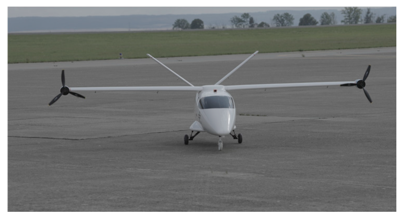
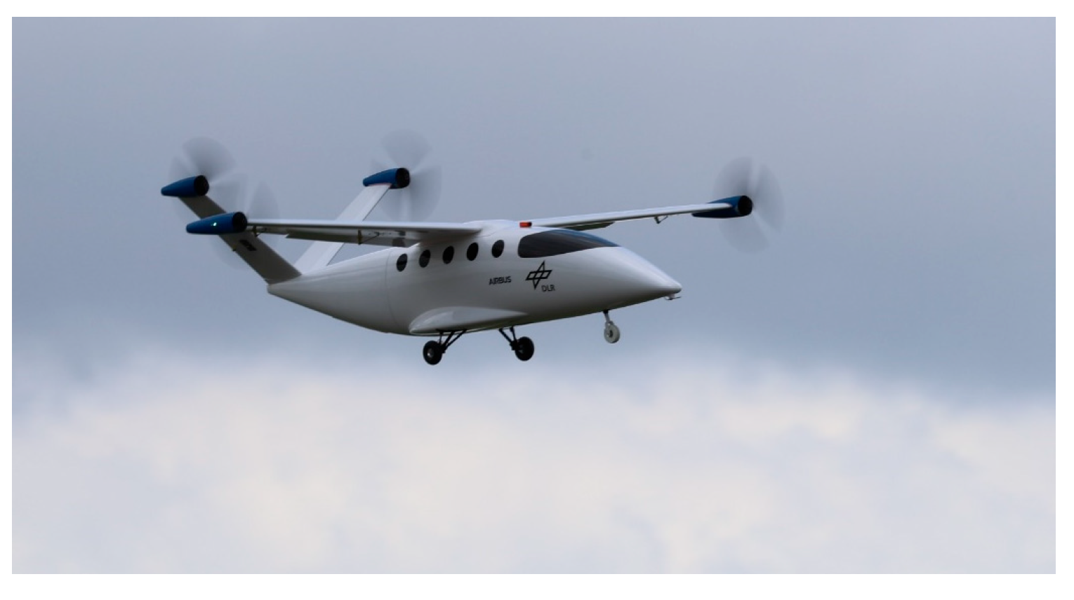
The first flight test campaign was conducted in July 2023 and consisted of two experiments with different aircraft configurations. In the first experiment, the initial configuration of the HyBird concept was tested, including four engines at the end of the wings and the end to the empennage (Figure 4). In a second experiment a two-engine configuration was tested with only the two propellers mounted at the wing tips (Figure 5).
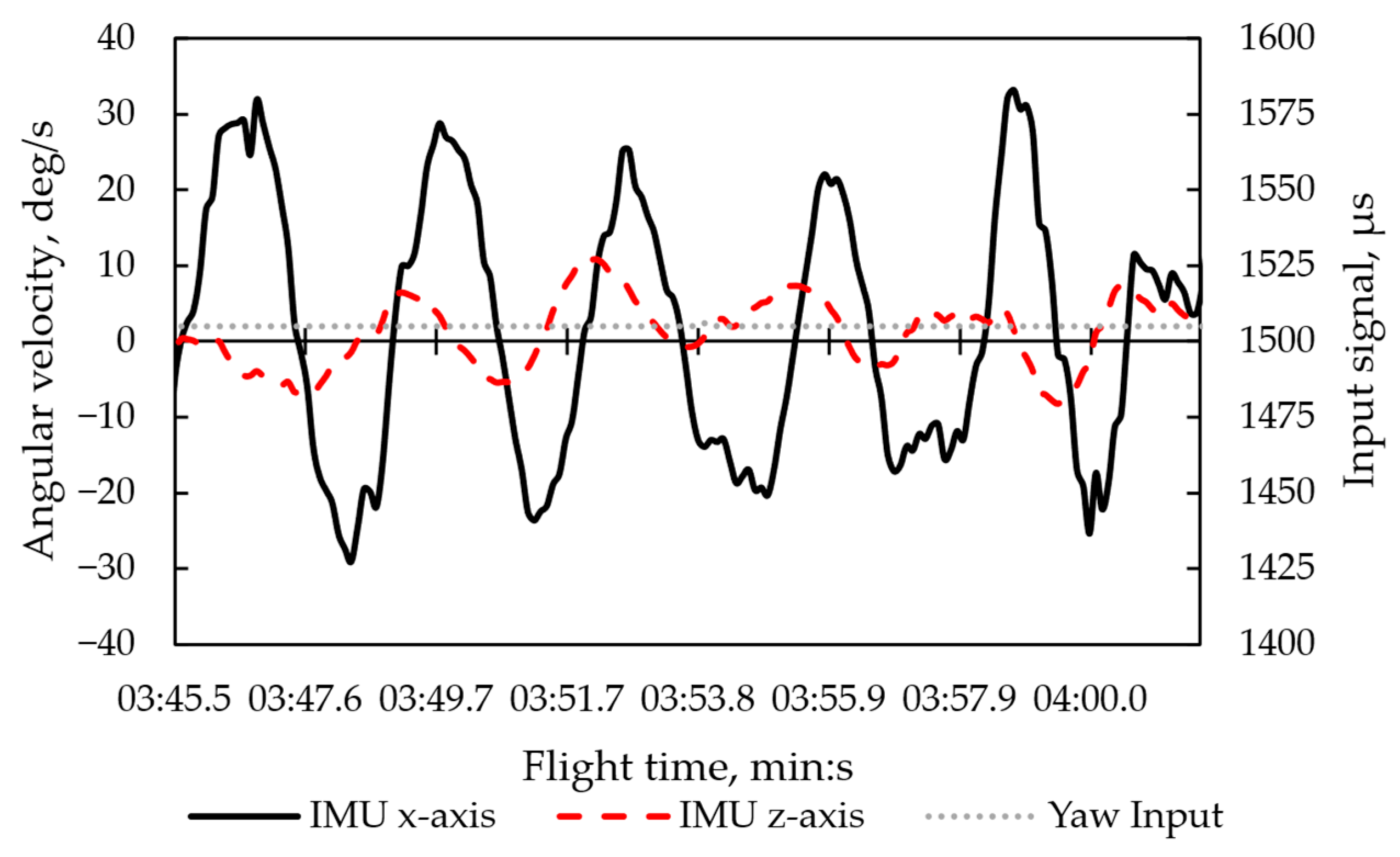
Challenges which arose during the initial flight tests involved the Dutch roll behavior during several flight states and the increased pitch down moment when the throttle was rapidly increased. In addition, the demonstrator’s controllability in turn was undesirable for the pilot, since the flight control system was not tuned for the unconventional propulsor placing. It was not possible to fly coordinated turns as the propulsor at the wing tips affected the UAS motion extensively. The control surfaces at the empennage were sized too small to counteract the additionally induced yaw moments from the wing tip propeller. The small control surfaces and a respectively high center of gravity in the UAS z-direction led to a noticeable Dutch roll behavior in the first flight experiment. This oscillating motion is depicted in Figure 6. In addition, the input from the pilot for the yaw signal is shown as the respective PWM signal, to state that the motion was not induced or enhanced by pilot input. Note that the full deflection of the yaw inputs ranges from 1000 µs to 2000 µs.
A significant induced pitch moment occurred during a go-around maneuver at the first flight. During a go-around maneuver the propulsive power is increased rapidly. Due to the increased thrust from the electric motors at the tip of the empennage, a pitch down moment is induced. Since these induced pitching moments lead to critical flight states in the first flights, the rear motors were removed and the next flight test was conducted with only two motors and half of the propulsive power. Significant changes in the Dutch roll behavior were observed during the second experiment. The differences in the overserved differences in the periodic motions are summarized in Table 3.
Comparing both flights, a significant decrease in the amplitudes of the roll and yaw motion were observed. These changes were reported from the pilot and the observer after the flight. The Dutch roll motions were made less critical by removing the rear motors and the lower center of gravity in the z-direction. As expected, the motor-induced nose-down moments were eliminated, and maintaining controllability during the go-around maneuver was no issue.
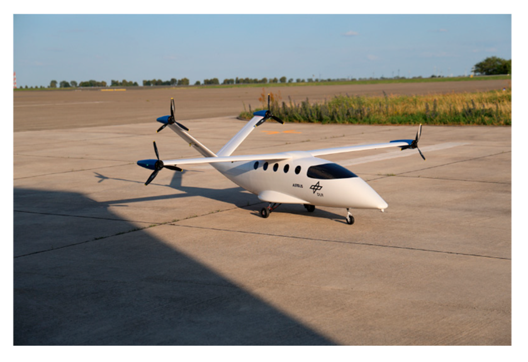
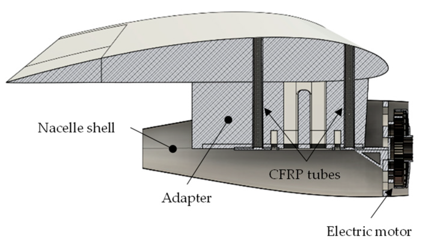
The yaw steering of the demonstrator was still a problem. For this reason, a larger empennage was designed and differential thrust values were implemented in the flight control system. In addition, the motor configuration was changed to a four-engine configuration, with all motors mounted on the wing. Figure 7 shows the modified HyBird demonstrator in a four-engine configuration and with a larger empennage design. To mount the electric engines under the wing, a specific structure was added to the wings, displayed in Figure 8.
A form-fitting adapter, made in a fused deposition modeling (FDM) process, is mounted underneath the wing to secure the nacelle, including the electric motor. The adapter is glued to the wing with two carbon fiber-reinforced plastic (CFRP) tubes. The horizonal and vertical projected area of the V-Tail was increased by 5%, while the projected areas of the control surfaces were increased by 38% to enhance the pilot’s control authority.
The differential thrust setting was programmed in the flight control systems and applied to the two outer engines on the wing. This setting was implemented with a percentage value. The percentage value defines the commanded thrust difference to the outer motors when the rudder stick is fully deflected to one side. During the test flights differential thrust settings between 0% and 30% were tested.
With these modifications a second flight test campaign was conducted in July 2024. The airfield and the general flight test procedure remained unchanged compared to the first flight test campaign. The center of gravity in the x-direction was located 1385 mm behind the aircraft’s nose and within the calculated range from the design process.
During the flight tests the handling qualities of the UAS were improved substantially compared to the first flight test campaign. After the initial flight, the pilot and the ground observer reported the elimination of all Dutch roll motions and sufficient handling qualities of the UAS during the mission. This was mainly achieved due to the adapted empennage design. Although the handling qualities and controllability with the larger empennage were sufficient, the implemented differential thrust settings were tested in a later stage of the campaign. During the test, several percentage values were tested between 0% and 30%. The first tested value of 30% resulted in an oversensitive steering behavior of the UAS. A comparable minor pilot yaw input results in a significant angular velocity of the UAS. With further testing, a differential thrust setting of about 10% seems more fitting with the programmed rudder deflections. Note that the differential thrust setting is heavily dependent on the programmed control surface deflections.
An undesired effect that occurred during this second campaign was an instability during high-speed taxiing. The instabilities arose near the rotational speed for take-off and were noticed around the yaw and roll axis of the UAS. Such a behavior is undesirable for pilots, especially during take-off in gusty or crosswind conditions. A maximum angular velocity of −90 deg/s was observed during multiple experiments. With rapid counter inputs from the pilot, it was possible to stabilize the UAS. The instabilities are mainly caused by the implemented differential thrust settings in the flight control system, as the differential thrust settings were initially active during the take-off. Small rudder inputs to align the UAS with the runway can lead to a significant yaw moment, inducing instabilities. The differential thrust setting should be disabled for take-off and landing in future experiments. To increase the stability during taxi and take-off even further, the maximum nose wheel deflection was programmed to be dependent on the ground speed of the UAS. For higher ground speeds the maximum allowable nose wheel deflections were reduced.

4. Conclusions and Outlook

In the first flight experiments, undesired flight characteristics were identified because the propulsors were located high above the wings and at the wing tips. This resulted in an unusual position of the center of gravity regarding the z-axis of the UAS. A Dutch roll motion was observed in multiple flight stages as well as a pitch down moment when rapidly increasing the throttle. The flight characteristics were improved in a second experiment, where only the wing tip propellers were mounted, and as a result the center of gravity had a lower z-position. To enhance the flight characteristics further a larger empennage was designed and the UAS was tested in a four-engine configuration. During these experiments, the flight characteristics were significantly improved. Differential thrust settings were implemented in the flight control system to further increase the handling of the UAS with the tested engine configuration.
With the increased interest of DEP concepts in recent years, a second modified version of the HyBird demonstrator was designed and built to investigate the flight characteristics of a DEP concept. The results from the second flight test campaign with the four-engine configuration constitute a baseline for the upcoming flight experiments with the new demonstrator. Future experiments with the second HyBird demonstrator can give the first insights into the flight behavior of a scaled UAS with multiple propellers mounted at the wing, similar to a DEP concept. These findings can be transferred to other UAS projects or can influence the design of future DEP aircraft concepts.

Author Contributions

Conceptualization, T.H.; methodology, T.H.; software, T.H.; validation, T.H.; formal analysis, T.H.; investigation, T.H.; resources, T.H.; data curation, T.H.; writing—original draft preparation, T.H.; writing—review and editing, T.H., S.d.G. and A.T.; visualization, T.H.; supervision, S.d.G. and A.T.; project administration, S.d.G.; funding acquisition, S.d.G. All authors have read and agreed to the published version of the manuscript.

Funding

This research received no external funding.

Institutional Review Board Statement

Not applicable.

Informed Consent Statement

Not applicable.

Data Availability Statement

The data presented in this study are available on request from the corresponding author. Data are not publicly available due to privacy or ethical restrictions.

Acknowledgments

The authors would like to express their gratitude to all project members from the DLR project FGAA for their wide-ranging support during all flight test campaigns. Additionally, the construction and building process for the HyBird demonstrator was conducted to a large extent by the Airbus ProtoSpace in Hamburg. They also supported this work with their expertise during all flight test campaigns.

Conflicts of Interest

The authors declare no conflicts of interest.

References

  1. European Union. Flightpath 2050 Europe’s Vision for Aviation; European Union: Brussels, Belgium, 2011. [Google Scholar]
  2. Air Transport Action Group (ATAG). Waypoint 2050: An Air Transport Action Group Project; ATAG: Geneva, Switzerland, 2021. [Google Scholar]
  3. Kim, H.D.; Perry, A.T.; Ansell, P.J. A Review of Distributed Electric Propulsion Concepts for Air Vehicle Technology. In Proceedings of the 2018 AIAA/IEEE Electric Aircraft Technologies Symposium, Cincinnati, OH, USA, 9–11 July 2018. [Google Scholar] [CrossRef] [Scilit]
  4. Hospodář, P.; Klesa, J.; Demovič, D.; Žižkovský, N. Aerodynamic and Structural Aspects of a Distributed Propulsion System for Commuter Airplane. Aerospace 2022, 9, 712. [Google Scholar] [CrossRef] [Scilit]
  5. Habermann, A.L. Effects of Distributed Propulsion on Wing Mass in Aircraft Conceptual Design. In Proceedings of the AIAA Aviation 2020 Forum, Virtual Event, 15–19 July 2020. [Google Scholar] [CrossRef] [Scilit]
  6. Schmollgruber, P.; Atinault, O.; Cafarelli, I.; Döll, C.; François, C.; Hermetz, J.; Liaboeuf, R.; Paluch, B.; Ridel, M. Multidisciplinary Exploration of DRAGON: An ONERA Hybrid Electric Distributed Propulsion Concept. In Proceedings of the AIAA Scitech 2019 Forum, San Diego, CA, USA, 7–11 January 2019. [Google Scholar] [CrossRef] [Scilit]
  7. Moore, K.R.; Ning, A. Takeoff and Performance Trade-Offs of Retrofit Distributed Electric Propulsion for Urban Transport. J. Aircr. 2019, 56, 1880–1892. [Google Scholar] [CrossRef] [Scilit]
  8. EASA. Certification Specifications for Normal Category Aeroplanes (CS-23), 2023. Available online: https://www.easa.europa.eu/en/document-library/easy-access-rules/easy-access-rules-normal-category-aeroplanes-cs-23 (accessed on 28 November 2025).
  9. Mangold, J.; Lang, M.; Stober, J.; Ladwein, F.; Will, F. NASA/DLR Design Challenge 2019 HyBird Aircraft Concept. 2019. Available online: https://www.dlr.de/en/media/publications/miscellaneous/2019/concept-university-stuttgart-hybird/@@download/file (accessed on 8 July 2025).
  10. Will, F.; Flüthmann, N.; Eschmann, C. Derivation of Top-Level Aircraft Requirements for Small Aircraft Transport by Modelling Demand in Europe. In IOP Conference Series: Materials Science and Engineering; IOP Publishing: Bristol, UK, 2022. [Google Scholar] [CrossRef] [Scilit]
  11. Will, F.; Ladwein, F.; Zill, T. Design and evaluation of novel general aviation aircraft concepts with a fully integrated powertrain for regional air mobility. In Proceedings of the AIAA Aviation 2023 Forum, San Diego, CA, USA, 12–16 June 2023. [Google Scholar] [CrossRef] [Scilit]
  12. Hammer, T.; de Graaf, S. Evaluation of hybrid electric powertrain topologies and their integration in future aircraft concepts for general aviation. In Proceedings of the Aerospace Europe Conference 2023, Lausanne, Switzerland, 9–13 July 2023. [Google Scholar] [CrossRef]
  13. Sobron, A. On Subscale Flight Testing: Cost-Effective Techniques for Research and Development; Linköping University: Linköping, Sweden, 2021. [Google Scholar]
  14. Sobron, A.; Lundström, D.; Krus, P. A Review of Current Research in Subscale Flight Testing and Analysis of Its Main Practical Challenges. Aerospace 2021, 8, 74. [Google Scholar] [CrossRef] [Scilit]
  15. Wolowicz, C.H.; Bowman, J.S., Jr.; Gilbert, W.P. Similitude Requirements and Scaling Relationships as Applied to Model Testing; NASA Technical Paper 1435; NASA: Washington, DC, USA, 1979.
  16. Chamber, J.R. Modeling Flight The role of Dynamically Scaled Free Flight Models in Support of NASA Aerospace Programs. 2010. Available online: https://www.nasa.gov/wp-content/uploads/2015/01/601262main_ModelingFlight-ebook.pdf (accessed on 21 October 2025).
  17. Nguewo, D. Erstellung und Optimierung der Skalierungsgesetze zur Abschätzung der Aerodynamik und der Eigendynamik eines Flugzeugs auf der Basis von frei Fliegenden Modellen. Ph.D. Thesis, University of Stuttgart, Stuttgart, Germany, 2007. [Google Scholar]
  18. Lundstrom, D.; Sobron, A.; Krus, P.; Jouannet, C. Subscale Flight Testing of a Generic Fighter Aircraft. 2016. Available online: https://icas.org/icas_archive/ICAS2016/data/papers/2016_0390_paper.pdf (accessed on 21 October 2025).
  19. EASA. Easy Access Rules for Unmanned Aircraft Systems. 2024. Available online: https://www.easa.europa.eu/en/document-library/easy-access-rules/easy-access-rules-unmanned-aircraft-systems-regulations-eu (accessed on 28 November 2025).
  20. ArduPilot Plane—Plane Documentation. Available online: https://ardupilot.org/plane/ (accessed on 8 July 2025).
  21. German Aerospace Center (DLR). DLR Site Cochstedt. Available online: https://www.dlr.de/en/dlr/locations-and-offices/cochstedt (accessed on 21 October 2025).
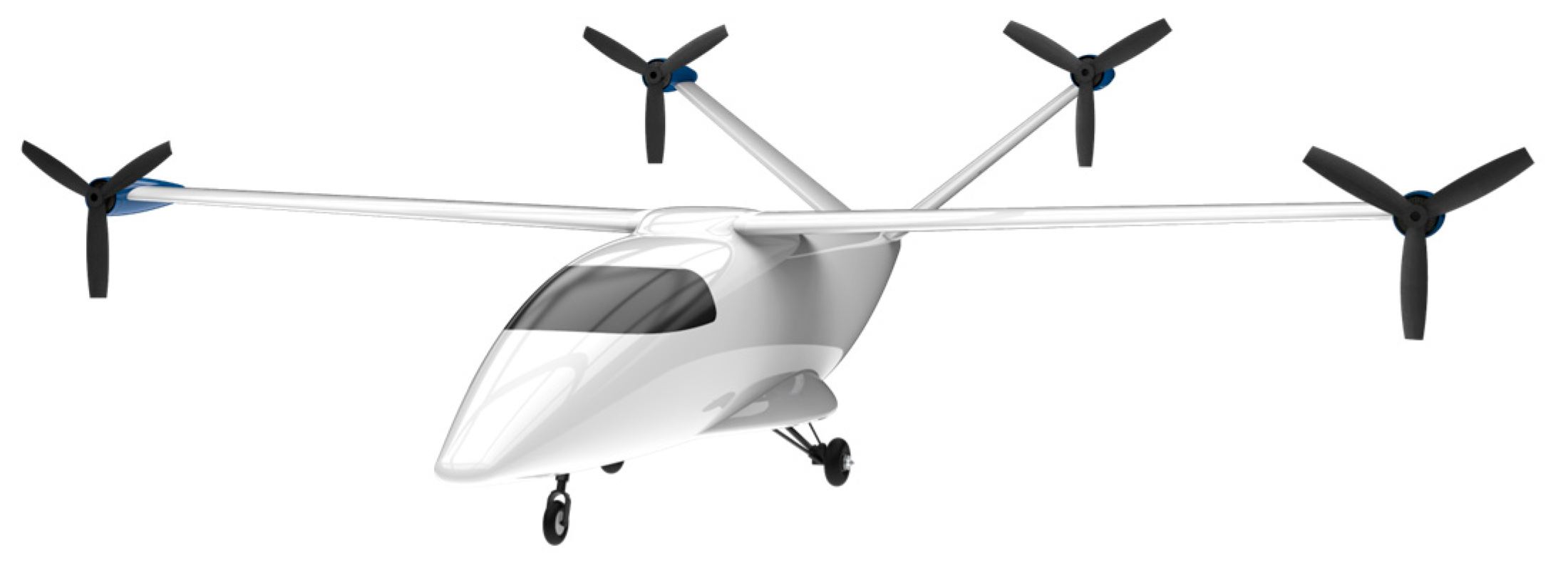
Figure 1. Rendering of the HyBird demonstrator.
Engproc 133 00106 g001
Figure 2. Scaled HyBird before maiden flight.
Engproc 133 00106 g002
Figure 3. Coordinate system applied in this study, displayed in a front view.
Engproc 133 00106 g003
Figure 4. HyBird demonstrator during first test flight.
Engproc 133 00106 g004
Figure 5. HyBird demonstrator after second flight experiment.
Engproc 133 00106 g005
Figure 6. Dutch roll behavior during first flight experiments.
Engproc 133 00106 g006
Figure 7. HyBird with a four-engine configuration.
Engproc 133 00106 g007
Figure 8. Mounting structure for the electric propulsor under the wing.
Engproc 133 00106 g008
Table 1. Basic parameters about the full-scale HyBird concept [9].
ParameterValue
Wingspan, m14.15
Length, m12.8
MTOM, kg3782
Cruise speed TAS, m/s136
Design range, km703
PAX9
Table 2. Basic parameters of the scaled HyBird UAS.
ParameterValue
Wingspan, m3.52
Length, m3.102
MTOM, kg25
Cruise speed, m/s20–22
Endurance, min25
Table 3. Comparison of the Dutch roll behavior in the first two flights.
Parameter1st Flight Test2nd Flight Test
Period roll motion, s32.1–2.7
Frequency roll motion, Hz0.330.37–0.47
Amplitude roll motion, deg/s20–3010–25
Period yaw motion, s32.1–2.8
Frequency yaw motion, Hz0.330.36–0.47
Amplitude yaw motion, deg/s6–104–7
Disclaimer/Publisher’s Note: The statements, opinions and data contained in all publications are solely those of the individual author(s) and contributor(s) and not of MDPI and/or the editor(s). MDPI and/or the editor(s) disclaim responsibility for any injury to people or property resulting from any ideas, methods, instructions or products referred to in the content.