1. Introduction
Hydraulic brakes work based on Pascal’s law, which states that “pressure acting in an enclosed system is the same in all directions”. According to this law, when the pressure is applied on a fluid it will travel equally in all directions, and hence a uniform braking action is applied on all four wheels.
Brake fluid is hygroscopic, which means it tends to absorb moisture. This can be a problem because higher moisture content leads to a lower boiling point—therefore, the older the brake fluid, the less effective it is. Various malfunctions in the braking system are closely related to traffic safety and a leading cause of accidents, which is analysed in [
1].
The hygroscopic property of brake fluid is required so that any water present distributes itself evenly throughout the liquid. If water is collected in a specific area, the boiling point will decrease to approximately 100 °C. However, if the water is dissolved in the brake fluid up to a proportion of 3%, for example, the boiling point will remain significantly higher than 100 °C, where the risk of bubble formation is much lower.
When driving aggressively on windy mountain roads or race circuits, brake pads can reach over 300 °C. This high heat is passed onto the brake fluid through the callipers, which can raise the fluid temperature over 200 °C. In [
2] an analysis of heat transfer between the individual elements of a disc brake system is presented. If the brake fluid is repeatedly heated past its boiling point, some of the fluid vaporizes and creates bubbles within the brake lines. This is a very dangerous situation since this can lead to what is commonly known as vapour lock, or simply the brakes not working. This occurs since the vapour is compressed instead of the fluid so the brake pads do not move [
3,
4].
Brake fluid boils when it reaches its boiling point due to excessive heat in the brake system, usually from intense or prolonged braking. When brake fluid boils, it creates gas bubbles within the system. As gas is compressible, unlike liquid brake fluid, these bubbles reduce the hydraulic pressure transmitted through the brake lines, resulting in decreased braking efficiency, also known as “brake fade”.
The boiling point of a brake fluid is the temperature at which gas bubbles form. As soon as a gas bubble forms, the pressure in the brake system can no longer be maintained because the gas can be compressed. The consequence is a sudden reduction in braking effectiveness, which can lead to an accident.
Dry boiling point describes the property of the sealed new brake fluid. In this state, the brake fluid is almost anhydrous (a substance containing no water). The dry boiling point is usually between 240 and 280 °C.
Wet boiling point describes the property of the brake fluid at the end of its life cycle, at a water content of 3.7%, when the fluid should be replaced. This defined wet boiling point must not be undercut [
5].
In [
6,
7,
8,
9], the influence of the water level in the brake fluid on the rate of increase in the temperature of the brake fluid and the boiling point of the brake fluid was determined and the direct relationship between these two indicators was proven. The influence of the temperature in the contact of the friction pair of the brake system on the elements was considered in [
10,
11,
12,
13,
14,
15]. The considered studies did not determine the moment at which the failure of the brake system occurs, which is essential for ensuring traffic safety.
2. Materials and Methods
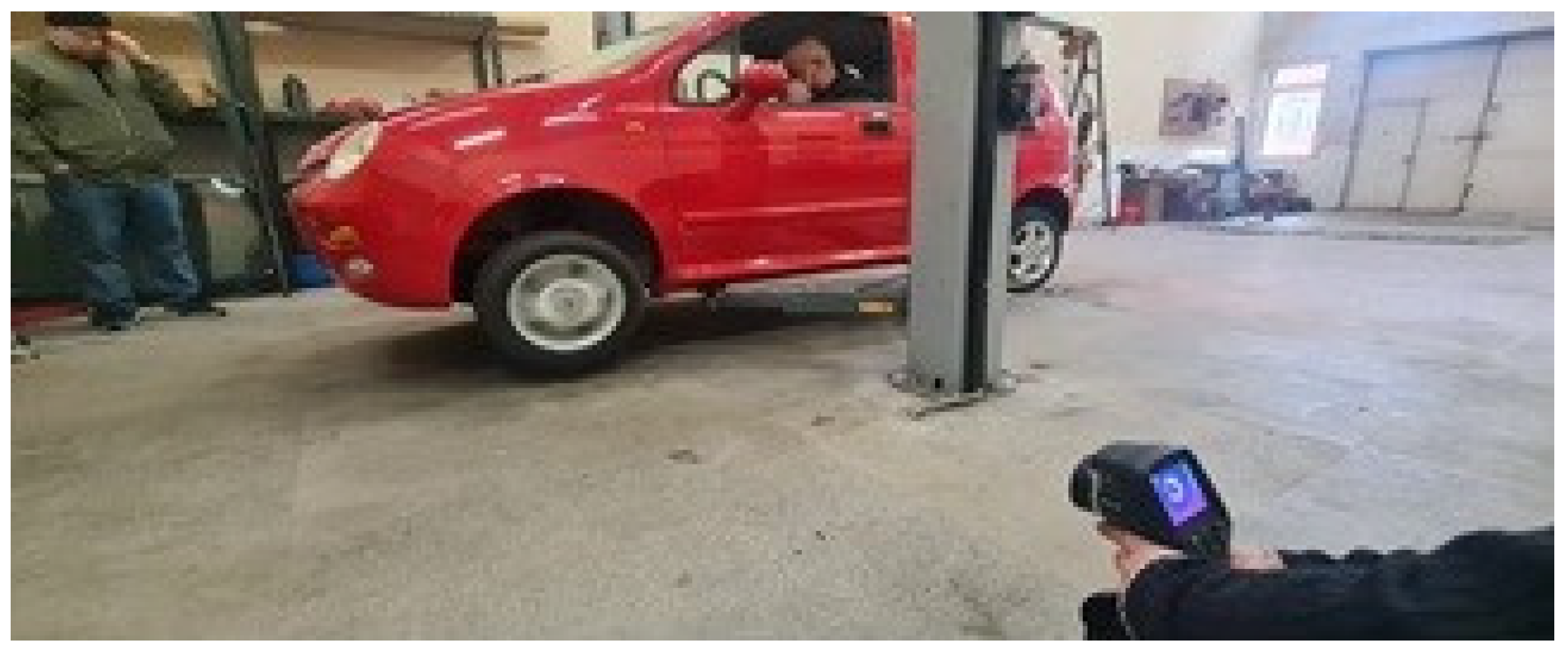
For the purposes of this study, a laboratory experiment was conducted to determine the influence of brake fluid on the braking efficiency of a car. The laboratory study was conducted on a Chery model QQ car. The vehicle was lifted on a lift and its movement was simulated, and at the same time the brake system was activated, but with such an effort that it was less than the torque supplied to the drive wheels by the internal combustion engine, which did not cause the drive wheels to lock. In this way, the brake discs were quickly heated to temperatures above 400 °C, as shown in
Figure 1.
The temperature measurement was performed with a Flir E 40 thermal camera from a distance of about 2 m, which ensured the necessary focal length of the camera and maintained the necessary safety when performing the experiment, which is also shown in
Figure 1. The FLIR E40 thermal imaging camera, which is shown in
Figure 2a, has the following main features: Multi-Spectral Dynamic Imaging (MSX) for easier interpretation of an image; −20 to 650 °C temperature range; 19,200 pixel resolution (160 × 120); thermal sensitivity: <0.07 °C; fixed picture-in-picture; onboard 3.1 MP digital camera; 3.5″ touchscreen display with auto-orientation; 3 spotmeters; image annotation (voice + text); 25° × 19° field of view; 7.5 to 13 µm spectral range; stores over 1000 radiometeric JPEG images on an SD card; manual-focus lens with 2× continuous digital zoom; MeterLink technology embeds information from compatible clamp and moisture meters onto thermal images; FLIR Tools Mobile connects to compatible smartphones and tablets via Bluetooth.
When measuring temperature with a thermographic camera, the measured object is photographed, which in this case is the brake disc on the front left wheel. During the photographing, the camera takes two simultaneous photos, one of which is the actual image, and the other is a thermographic image of the object. Images of the brake disc during the measurement are shown in
Figure 2b. The thermographic image shows that at the moment of photographing, a temperature of 451 °C was measured at the point on the brake disc where the camera target is located.
The temperature measurement of objects can be performed in various ways using the appropriate measuring equipment. The most common methods are through direct temperature measurement, in which contact is made between the measuring devices and the object under study. In these cases, K thermocouples are most often used to measure temperature. This method is easily applicable when measuring the temperature of surfaces of stationary objects or fluids in closed volumes. It is widely used for monitoring temperatures in automotive units as part of the control and diagnostic equipment in vehicles, as well as when performing bench tests of vehicle units such as internal combustion engines to monitor the temperature of various fluids, as a current parameter in the testing process, as was performed in [
16,
17,
18]. Another method of measurement is through the use of non-contact methods for measuring temperature using thermal chambers. Thermographic studies using various measuring devices, including a FLIR E40 thermographic camera, were conducted by [
19,
20,
21,
22,
23]. The non-contact temperature measurement of moving objects is based on Planck’s law, which presents the theory of the self-electromagnetic radiation of bodies and is described in detail in [
24,
25,
26,
27,
28].
When the brake disc temperature reached 400 °C, the vehicle was removed from the lift and placed on a brake stand to measure the braking force and cool the brake discs. When the temperature dropped below 100 °C, the measurement of the braking efficiency was stopped and the brake system was subjected to further heating of the brake discs to 400 °C according to the methodology described above. The ambient temperature in the room where the laboratory study was conducted was 11 °C and the time required to cool the brake discs from 400 °C to 100 °C was within the range of about 30 min. It took about 2 min to heat the brake discs again to a temperature in the range of 400 °C.
The brake dynamometer is a HPA test model used to determine the braking efficiency of light and heavy vehicles. The braking force readings are read on the brake dynamometer dashboard using analogue indicators.
Figure 3a shows the measuring board of the stand with readings of the analogue indicator for the realized braking force of the left wheel, while
Figure 3b shows the placement of the front left wheel of the vehicle on the rollers of the brake stent during measurement of the braking force.
To measure the boiling point of the brake fluid, a device from the manufacturer ALBA Diagnostics, shown in
Figure 3c, was used. The Alba patented brake fluid tester is approved, recommended and sold by the world’s leading brake system and brake fluid manufacturers, as well as leading global aftermarket brands. The Alba brake fluid tester works on the boiling point method, the only industry approved method that guarantees reliable, repeatable and accurate test results.
The Alba Diagnostics brake fluid meter operates on a 12 V power supply, which ensures that it can be powered by the vehicle’s own battery and measures up to 320 °C, suitable for use on all grades of new and used brake fluids.
To perform the boiling point measurement, each of the individual brake fluid samples was poured into a glass transparent flask, which had to be clean and dry, as shown in
Figure 4a.
The measurement of the boiling point of the respective brake fluid sample was performed by immersing the tester probe into the flask to the required depth according to the manufacturer’s instructions for a period of 30 s, as shown in
Figure 4b.
3. Results and Discussion
When measuring the braking forces using the above-described method, a complete loss of the vehicle’s braking properties was found after three consecutive warm-ups to 400 °C and cooling to 100 °C. The reason for the complete loss of the vehicle’s braking properties was that when measuring the temperature of the brake discs of the brake system, the dissipation of the heat generated by them in other elements, such as brake callipers, is not taken into account. It is in the brake callipers that the brake cylinders, which are filled with brake fluid, are located. In this way, part of the dissipated heat was transferred to the brake fluid in the system, which led to an excessive increase in temperature. This increase in temperature led to the boiling of the available water from the moisture absorbed in the brake fluid and the formation of gas bubbles, which led to the failure of the brake pedal and, accordingly, the complete failure of the brake system of the tested vehicle.
In real road conditions, this situation can occur when a car is driven aggressively, accompanied by rapid acceleration and subsequent braking with maximum braking force. This driving style is often mistaken for driving in urban conditions. In [
29], measurements of the maximum and average accelerations of cars when passing through intersections in cities are presented.
Another situation in which an increase in temperature can be observed in the friction surfaces of the brake system elements is during a prolonged descent of the vehicle on a slope, typical of roads in mountainous areas.
For this reason, the boiling point of the brake fluid in the vehicle was measured and compared with brake fluid from other manufacturers. The results obtained for the boiling point temperatures for each individual fluid are presented in
Table 1.
For the comparison of the boiling point temperature of the vehicle brake fluid, three brake fluids from different manufacturers with the same specifications were used. The three brake fluids were DOT4 of the brands ATE, TRV and FEBI. The ATE brake fluid was unused, stored in the original packaging, but opened 5 years ago. The TRV brake fluid was used and drained from the vehicle 5 years ago. The FEBI brake fluid was new, stored in unopened packaging and opened when the measurement was carried out. For this reason,
Table 1 contains results for the dry boiling point temperature only for the FEBI brake fluid. The pH value of the tested brake fluids was between 7 and 8, which is within the permissible limits according to current regulatory documents.
The wet boiling point temperature of the Febi brake fluid was measured after the sample had been left outdoors for 2 h. The measured value, which is given in
Table 1, is 206 °C. This required subsequent measurements to determine the dependence of the change in the wet boiling point temperature on the time during which the brake fluid was in contact with the environment. For this purpose, additional measurements were carried out only for this brake fluid, using the same sample. Consecutive measurements were carried out at different time intervals—2 h, 4 h, 14 h and 72 h, respectively, after the first measurement of the wet boiling point temperature—and the results are presented in
Table 2.
The results from
Table 1 and
Table 2 are combined and presented in the graph in
Figure 5. The results obtained show that the characteristics of even a new, unused brake fluid that is in contact with moisture in the environment deteriorate below the permissible norms set out in the standards. If we proceed from the regularity that DOT4 brake fluid in an unsealed state has 0% weight units of water at a dry boiling point temperature above 254 °C and 3.7% weight units of water at 155 °C according to the approved standards, this means that after only 4 h of exposure to the influence of moisture in the environment, it absorbs 2.36% weight units of water.
4. Conclusions
From the results of this study, several main conclusions can be drawn.
When the brake system is repeatedly used with maximum braking force, which leads to an excessive increase in the temperature of the friction elements of the system, namely the brake disc and brake pads, if the system is not equipped with brake fluid coolers, this will lead to a rapid increase in the temperature of the brake fluid, exceeding the temperature of the wet boiling point. When this condition is reached, the water absorbed in the brake fluid will begin to boil and evaporate, which in turn will lead to the release of gas bubbles and, consequently, the failure of the brake pedal without creating braking force in the brake system. This condition is equivalent to a complete failure of the brake system.
The situation described above is equivalent to prolonged extreme use of the brake system in various road sections. To avoid such a situation, excessive driving and use of the brake system in such conditions should not be allowed, to provide the necessary time for cooling the brake fluid.
High temperatures during excessive extreme use of the brake system have the most critical impact on the brake fluid in the system, and significantly less impact on other elements. This is because when the friction elements in the system overheat, the braking force decreases noticeably, while when the brake fluid overheats, a complete failure of the brake system and a complete loss of braking force occurs.
The study proved that a complete loss of the vehicle’s braking properties was found after three consecutive warm-ups to 400 °C and cooling to 100 °C.
With increasing time during which the brake fluid is in contact with the environment, a decrease in the boiling point is observed. After the first 2 h, the decrease is about 50 °C, which persists until the fourth hour, then after 12 h it drops by another 30 °C and the same after 72 h. It was found that after only 3 days the boiling point decreases by 106 °C and reaches a value of 148 °C, which is almost the same as the boiling point of the brake fluid in the tested brake system. It was found that the water content in the brake fluid reached 2.36% by weight after 4 h in contact with the environment, and after 72 h it reached below the permissible limit of 3.7% according to approved standards. Therefore, when changing or topping up brake fluid, only brake fluid stored in a sealed container and taking into account the expiration date should be used.


