Article

PSO-Based Robust Control of SISO Systems with Application to a Hydraulic Inverted Pendulum

by
Michael G. Skarpetis
*,
Nikolaos D. Kouvakas
,
Fotis N. Koumboulis
and
Marios Tsoukalas
Robotics, Automatic Control and Cyber-Physical Systems Laboratory, Department of Digital Industry Technologies, School of Science, National and Kapodistrian University of Athens, Euripus Campus, 34400 Psahna, Greece
*
Author to whom correspondence should be addressed.
Eng 2025, 6(7), 146; https://doi.org/10.3390/eng6070146
Submission received: 27 April 2025 / Revised: 20 June 2025 / Accepted: 22 June 2025 / Published: 1 July 2025
(This article belongs to the Special Issue Interdisciplinary Insights in Engineering Research)

Abstract

This work will present an algorithmic approach for robust control focusing on hydraulic–mechanical systems. The approach is applied to a hydraulic actuator driving a cart with an inverted pendulum. The algorithmic approach aims to satisfy two robust control requirements for single input single output (SISO) linear systems with nonlinear uncertain structure. The first control requirement is robust stabilization, and the second is robust asymptotic command following for arbitrary reference signals. The approach is analyzed in two stages. In the first stage, the stability regions of the controller parameters are identified. In the second stage, a Particle Swarm Optimization Algorithm (PSO) is applied to find suboptimal solutions for the controller parameters in these regions, with respect to a suitable performance cost function. The application of the approach to a hydraulic actuator, driving a cart with an inverted pendulum, satisfies the goal of achieving precise control of the pendulum angle, despite the system’s inherent physical uncertainties.

1. Introduction

The problem of robust stabilizability and command following for SISO linear uncertain systems is highly relevant to hydraulic systems and other applications, as explored in various studies (for an indication, see [1,2,3,4,5] and the references therein). In [1], a robust asymptotic tracking controller for step-type signals was proposed for the precise positioning of an industrial hydraulic actuator, addressing uncertainties and unknown disturbances. The stability regions were defined using a Hurwitz invariability algorithm, and the optimal parameters were determined through a Sine–Cosine Swarm optimization. In [2], a robust PID controller was developed for positioning the piston rod of a hydraulic servo actuator under varying pressure conditions, with experimental validation confirming its improved performance across different pressure levels. In [3], a recursive algorithm for the robust stabilization of uncertain gain-controlled polynomials, utilizing Hurwitz invariability and simulated annealing techniques, was presented. The recursive algorithm was applied to a hydraulic system for force control. In [4], a robust internal model control scheme was applied to linear plants with nonlinear uncertainties. The scheme incorporates a Heuristic Algorithm to determine robust controller parameters for sinusoidal signals. In [5], robust asymptotic position tracking was addressed for a hydraulic servo system with uncertainties, using the Internal Model Principle, incorporating uncertain parameters arising from the linearization of the servo valve and variations in the cylinder’s initial volume.
The main contribution of this work is the development of a novel robust tracking approach for arbitrary reference signals, being integrated with Particle Swarm Optimization (PSO), tailored for linear time-invariant systems with nonlinear uncertain structure. This approach employs a robust asymptotic tracking controller to ensure precise tracking performance and stability despite model physical uncertainties. The proposed PSO algorithm optimizes suboptimal controller parameters by minimizing a suitable performance cost function, ensuring effective adaptation and tracking performance across a wide range of system uncertainties.
Particularly, an approach is developed towards the derivation of a solution to the robust stabilizability and tracking problem for any signal produced by an autonomous dynamic system and any linear SISO system with nonlinear uncertain structure. Particular attention is given to the dynamic characteristics of a hydraulic pendulum, focusing on signals that exhibit exponential decay modulated by a linear term. These signals will be utilized to excite the pendulum and evaluate the robustness of the system in restoring the pendulum to its initial position. The motivation of the present paper is based on the garnered significant interest due to the inherently unstable dynamics of the pendulum (see [6,7,8,9,10,11]) and the physical uncertainties of the hydraulic actuators. This has driven the development of algorithms specifically designed to tackle robust control challenges in hydraulic systems. Hydraulic and pneumatic pendulums have attracted the interest of many works in the field. In [12], deep Reinforcement Learning (RL) was employed to control an inverted hydraulic pendulum, demonstrating the effectiveness of RL in complex hydraulic control tasks. In [13], a hydraulic double inverted pendulum was developed for educational and research purposes, focusing on modeling, control design, and implementation. In [14] special attention was paid to the modeling and control of a pneumatic inverted pendulum, using LQ and LQG controllers to handle nonlinear friction. In [15], the design of a hydraulic inverted pendulum system, covering both hardware and software aspects is presented. Lastly, ref. [16] compares different control strategies for a cart inverted pendulum with electric and pneumatic actuation, designed to meet system constraints and response targets. Robust control strategies are essential to enhance the safety, reliability, and availability of hydraulic actuators under variable conditions (see [17,18,19,20,21,22,23,24,25,26,27,28,29,30,31] and references therein).
The remainder of this paper is organized as follows. Section 2 outlines the methodology used for the proposed robust controller design. Section 3 presents the robust control framework, including the finite-step algorithms and corresponding stability conditions. Section 4 focuses on modeling the hydraulic actuator system, defining the uncertainty parameters and detailing the step-by-step controller derivation. Section 5 describes the implementation of the controller in the hydraulic–mechanical application and discusses the simulation results. Section 6 provides a comparative study to evaluate the effectiveness of the proposed controller against several well-established control strategies. Finally, Section 7 concludes the paper and highlights directions for future research.

2. Materials and Methods

The present study introduces finite-step algorithms that address various robust control requirements, including robust stabilizability, and asymptotic command tracking. These algorithms are designed to handle linear systems with inherent physical uncertainties, making them particularly suitable for hydraulic control applications. Designing robust controllers for systems with hydraulic actuators integrated into mechanical structures is crucial, as these systems are widely used across industries, including manufacturing, robotics, construction, and avionics. The dynamics of fluid power systems, combined with uncertain parameters due to variable operating conditions (such as fluctuations in temperature, pressure, or entrained air and water) and other physical factors (e.g., wear-induced loss in the effective area of the actuator piston seal), are complex, uncertain dynamics.
The robust design approach of this study is based on the respective results of Hurwitz invariability [32,33,34,35,36,37]. The proposed technique will be extended with a Particle Swarm Optimization (PSO) algorithm [38,39,40,41,42,43,44,45,46,47,48] for a near-optimal selection of the controller parameters in the safe zone of the precious stability areas. PSO is a stochastic, population-based optimization method inspired by the collective behavior of social organisms. Similar to Genetic Algorithms, PSO employs a random search strategy but uses “swarm intelligence” for solution optimization. The proposed methodology begins with calculating stability regions that define parameter values capable of guaranteeing robust stability, even when faced with model uncertainties. The present PSO algorithm is employed to identify the optimal controller parameters by minimizing specific performance indices related to the system response. This two-stage approach ensures that the controller is both stable and finely tuned.
To evaluate the effectiveness of the algorithms, they will be applied to a hydraulic actuator connected to a cart equipped with an inverted pendulum. This setup simulates many applications in robotics and automation. The controller’s performance will be tested through simulations to demonstrate its effectiveness in uncertain environments.

3. Results

3.1. Robust Tracking Controllers for Arbitrary Reference Signals—Preliminary Results

Linear time-invariant single-input single-output (SISO) systems, with nonlinear uncertain structures, are expressed as
x ˙ t = A q x t + b q u t ,         y ( t ) = c ( q ) x ( t )
where x ( t ) R n is the state vector, u ( t ) R is the input, and y ( t ) R is the output. The matrices A ( q ) ( q ) n × n , b ( q ) ( q ) n × 1 , and c ( q ) ( q ) 1 × n are functions of the uncertainty vector q = q 1 q l Q , where Q denotes the uncertain domain. The set ( q ) is the set of the nonlinear functions of q . The uncertainties are time-invariant. Regarding the nonlinear structure of the system matrices, there are no constraints or specifications imposed (e.g., boundedness or continuity). First, a robust asymptotic tracking controller will be structured, using the framework outlined in [1,2,3,4,5]. The tracking reference signals will be chosen to move the pendulum away from its current state and force it to return to its initial position.
The general class of reference signals, considered here, are the signals produced by the autonomous dynamic system form.
x ˙ r t = A r x r t ;   y r ( t ) = c r x r ( t )
where y r ( t ) R , x r ( t ) R r × 1 and where
A r = 0 1 0 0 0 0 1 0 0 0 0 1 d r d r 1 d r 2 d 1 ,   c r = 0 0 1 .
To system (1), apply the dynamic controller [4]
x ˙ c t = A c x c t + b c ε t , υ t = c c x c t , u ( t ) = υ ( t ) + f r + 1 f n x ( t )
where
ε ( t ) = y ( t ) y r t
is the tracking error and where
A c = d 1 1 0 0 d 2 0 1 0 d r 0 0 0 ,   b c = f r f r 1 f 1 ,   c c = 0 0 1 .
The parameters f i ( i = 1 , . . . , n + r ) are the controller parameters. The closed-loop system block diagram is presented in Figure 1. As indicated by Equations (3)–(5) and illustrated in Figure 1, the controller provides output feedback, dynamic action based on the tracking error (namely, the difference between the system output and the reference signal), and static state feedback.
According to [4,32,33,34,35,36,37] the problem of arbitrary asymptotic command tracking is solvable if the controller parameters f i ( i = 1 , , n + r ) are chosen to robustly stabilize the following closed-loop system expressed in the following augmented state space form:
d d t x ~ t = A ~ q x ~ + b ~ q f ε ~ ( t ) z ( t )
x ~ ( t ) = ε ( t ) ε ( 1 ) ( t ) ε ( r 1 ) ( t ) z ( t ) T
A ~ q = A r e r c ( q ) 0 n × r A ( q ) ,   b ~ ( q ) = 0 r × 1 b ( q ) ,   e r = 0 ( r 1 ) × 1 1
z t = x r t + i = 1 r d i x r i t
ε ~ ( t ) = ε ( t ) ε ( 1 ) ( t ) ε ( r 1 ) ( t ) T
f = f 1 f n + r
The closed-loop characteristic polynomial of system (6) can be rewritten as follows:
p c l s , q , f = i = 0 n + r s i α n i q , f = [ s n + r s 0 ] W * q 1 f T
W * q = a ~ T ( q ) Ω ( q )
a ~ ( q ) = 1 α 1 ( q , 0 ) α n + r ( q , 0 )
Ω q = 0 0 0 α 1 1 ( q ) α 1 2 ( q ) α 1 n + r ( q ) α n + r 1 ( q ) α n + r 2 ( q ) α n + r n + r ( q )
and where
α i j ( q ) = α i ( q , f ) f k = 1 j = k , f k = 0 j k α i ( q , 0 ) i = 1 , , n + r , j = 1 , , n + r .
Theorem 1
[32,34]. The uncertain polynomial in (12) is robustly stabilizable, via the dynamic controller (3), if the following conditions are satisfied:
(i) 
The elements of  W * q  are continuous functions of the uncertainties;
(ii) 
There exists  n + r + 1 —row submatrix of  W * q  that is positive antisymmetric.
Remark 1
[32]. The class of systems satisfying condition (ii) of Theorem 1 can be broadened by considering the matrix  W * q T  instead of  W * q ,     w h e r e   T  is an appropriate invertible matrix, being independent of the uncertainties.
Remark 2
[32]. A function matrix  W * q  is positive antisymmetric if it can be generated from a vector function  c ̄ q  which is positive Hurwitz, via a sequence of positive augmentations (either up or down).  c ̄ q c 0 q c 1 q c υ 1 q T R υ × 1  is called the core of  W * q .
The definitions of positive antisymmetric and positive augmentation structures are provided in [32,34].

3.2. Robust Asymptotic Tracking Algorithms

Based on the above remarks, the columns of W * q can be adjusted according to the dimension of the positive invariant core, initiating the construction of W * q with either up or down augmentations. The resulting matrix, denoted as W * * q , contains υ 1 fewer columns. Without loss of generality, and using the invertible matrix T , these columns can be arranged as the last { μ 1 , μ 2 , , μ υ 1 } columns of W * q T . These column indices correspond to the respective zero controller parameters.
Given the conditions of Theorem 1, a finite-step algorithm (based on [1,2,3,4,5]) is presented (see Algorithm 1) to calculate the stability regions for the controller parameters. For simplicity in presentation, we consider only up augmentations here.
Algorithm 1: Computation of Hurwitz invariability regions
Start
Set the numbering indices σ = 0 and μ = 0 .
Construct a sequence (maximum n + r + 1 υ ) of positive up or down augmentation creating the matrix W * * ( q ) , starting from a positive Hurwitz core c ̄ ( q ) R υ × 1 W 1 ( q ) W 2 ( q ) W * * ( q )
  for σ = 1 , , n + r + 1 υ
ξ σ n u m b e r   o f   r o w s   o f   W σ
ε ~ 1 ε σ 1       ( ε σ > 0 )
p σ s ξ σ 1 s ξ σ + 1 s 0 W σ ( q ) ε ~ σ
Find stability region I σ = [ ε σ m i n , ε σ m a x ] such that p σ is Hurwitz invariant.
ε ~ σ + 1 ε σ + 1 ε σ m a x 1
  End
I I 1 × I 2 × × I n + r + 1 υ
f s t r 1 ε ~ n + r + 1 υ T ε ~ n + r + 1 υ , ε ~ n + r υ , ε ~ 1 , 1 , 0 , 0 υ 1 , ε ~ σ I σ σ = 1 , , n + r + 1 υ
End
Since the stability regions are defined by the previously mentioned algorithm, the optimal selection, within these regions, that minimizes the cost function is determined using Algorithm 2, which employs a PSO approach [38,39,40,41,42,43,44,45,46,47,48]. The goal of this algorithm is to find the best solution to the controller parameters ε ~ σ ( σ = 1 , 2 , . n + r + 1 υ ) inside the stability region I by minimizing the following cost function.
C f ( f , q ) = M i n   A v e r a g e C o s t q Q m i n f 0 t 0 y r t L 1 Y s 2
where Y ( s ) is the Laplace transform of the output of the closed-loop system. The cost function in (16) describes a nested optimization problem. The inner optimization m i n f 0 t 0 y r t L 1 Y s 2 is solved using Particle Swarm Optimization (PSO) to determine the optimal controller parameters within the predefined stability region, as established by Algorithm 1, across all possible values of the system uncertainties. The outer optimization M i n A v e r a g e C o s t q Q { . } evaluates the average performance of each controller, under different uncertainty values and selects the optimal controller that minimizes this average cost.
It is important to mention that in this study, the Integral of Squared Error (ISE) was chosen as the objective function for tuning the PSO-based controller, due to its effectiveness in penalizing both transient and steady-state errors. This makes it particularly suitable for applications requiring high stability and precision, such as the hydraulic inverted pendulum system. The primary objective of the proposed controller is to ensure robust stabilization alongside asymptotic command tracking. As demonstrated in references [49,50], the Integral of Squared Error (ISE) criterion provided superior performance with respect to the settling time in control applications. For comparative purposes, the Integral of Absolute Error (IAE) criterion was also assessed, yielding comparable results. This outcome further substantiates the appropriateness of employing the ISE criterion for the control problem under consideration.
Algorithm 2: Particle Swarm Optimization
Start
q Q
c o s t [ f , q ] m i n f 0 t 0 r r e f t L 1 Y ( s ) 2
Initialize the swarm:
n u m P a r t i c l e s n 0 ( N u m b e r   o f   p a r t i c l e s   i n   t h e   s w a r m )
i t e r a t i o n s μ 0 ( N u m b e r   o f   i t e r a t i o n s   f o r   t h e   P S O )
w I w 0 ( I n e r t i a   w e i g h t )
c 1 c 1 , 0   ( C o g n i t i v e p a r t i c l e c o e f f i c i e n t )
c 2 c 2 , 0   ( S o c i a l s w a r m c o e f f i c i e n t )
b o u n d s I
Initialize particle’s position
Initialize randomly particle’s velocity
   for j = 1 , , i t e r a t i o n s
r 1 R a n d o m R e a l
r 2 R a n d o m R e a l
( U p d a t e v e l o c i t y )
v e l o c i t i e s [ [ j ] ] w v e l o c i t i e s [ [ j ] ] + c 1 r 1 ( p a r t i c l e B e s t [ [ j ] ] p a r t i c l e s [ [ j ] ] ) + c 2 r 2 ( g l o b a l B e s t p a r t i c l e s [ [ j ] ] ) ;
( U p d a t e p a r t i c l e p o s i t i o n )
p a r t i c l e s [ [ j ] ] p a r t i c l e s [ [ j ] ] + v e l o c i t i e s [ [ j ] ] ;
n e w C o s t c o s t [ p a r t i c l e s [ [ j ] ] ] ;
I f   n e w C o s t < p a r t i c l e B e s t C o s t [ [ j ] ]
   p a r t i c l e B e s t j p a r t i c l e s j
   p a r t i c l e B e s t C o s t j n e w C o s t ;
end
I f   n e w C o s t < g l o b a l B e s t C o s t
     g l o b a l B e s t p a r t i c l e s j
     g l o b a l B e s t C o s t n e w C o s t
end
   End
D i s p l a y
g l o b a l B e s t
g l o b a l B e s t C o s t
M i n A v e r a g e C o s t q Q m i n g l o b a l B e s t 0 t 0 y r t L 1 Y s 2
End

4. Robust Controller for a Hydraulic Actuator Driving a Cart with Inverted Pendulum

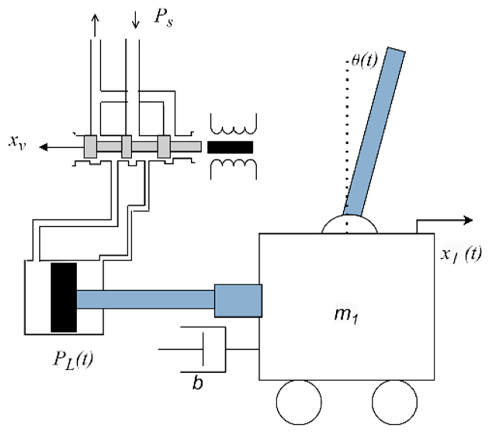
In this section, the nonlinear differential model that governs the behavior of a hydraulic actuator, connected to a cart with an inverted pendulum system (Figure 2), is [7,8,9,10,11]:
m 1 + m 2 x ¨ 1 t + b x ˙ 1 t m 2 L θ ˙ t 2 sin θ t + m 2 L θ ¨ ( t ) cos θ ( t ) = A p P L ( t )
Ι 2 + m 2 L 2 θ ¨ t + m 2 L x ¨ 1 t cos θ t + L g sin θ ( t ) = 0
where m 1 is the mass of the cart sliding system, m 2 is the mass of the pendulum, x 1 is the position of the vehicle, θ is the vertical angle of the pendulum, b is the viscous friction coefficient, L is the length of the pendulum center of mass, g is the acceleration due to gravity, P L ( t ) is the pressure difference across the ends of the piston, and A P is the surface area of the piston. The pressure at the ends of the piston is characterized by the following differential equation [17]:
d P L ( t ) d t = 4 β V t A p x ˙ 1 ( t ) ( C leak + K c ) P L ( t ) + K q x v ( t )
where β is the bulk modulus of the fluid, C l e a k is the leakage coefficient, V t is the total volume of the fluid in the piston and pipes, K q and K c are the pressure and the displacement flow coefficient of the hydraulic actuator, respectively, and x v ( t ) is the displacement of the spool valve of the actuator. The parameter K q represents the flow gain of the valve. This parameter is treated as an uncertain parameter representing the variability and nonlinear characteristics, being inherent in real valve behavior [17].

4.1. Linear Approximant

Let θ = θ 0 + φ , where θ 0 = π and φ is a small deviation of θ from the vertical upward direction. Using the small perturbation theory, i.e., cos ( φ ) 1 , sin ( φ ) φ , and φ ˙ 2 0 from (17) and (18), we get:
m 1 + m 2 x ¨ 1 t + b x ˙ 1 t m 2 L φ ¨ t = A p P L t
Ι 2 + m 2 L 2 φ ¨ t m 2 L x ¨ 1 t m 2 L g φ t = 0
In light of the hydraulic system practice, the parameters K q , C l e a k , K c , and β are treated as uncertainties in this context:
q 1 = K q , q 2 = C l e a k , q 3 = K c , q 4 = β
The uncertain vector is q = q 1 , q 2 , q 3 , q 4 ϵ Q , where
Q = [ q 1 , m i n , q 1 , m a x ] × [ q 2 , m i n , q 2 , m a x ] × [ q 3 , m i n , q 3 , m a x ] × [ q 4 , m i n , q 4 , m a x ] .
Using (22), Equations (19)–(21) can be expressed in the state space form (1), with
x t = x ˙ 1 t φ t φ ˙ t P L t ,   A q = α 1 α 2 0 α 3 0 0 1 0 α 4 α 5 0 α 6 α 7 0 0 α 8 , B q = 0 0 0 β 1 , u t = x v t , C = 0 1 0 0
where
α 1 = b Ι 2 b L 2 m 2 m 1 ( Ι 2 + L 2 m 2 ) + Ι 2 m 2 ,   α 2 = g L 2 m 2 2 m 1 ( Ι 2 + L 2 m 2 ) + Ι 2 m 2 , α 3 = L 2 m 2 A p + Ι 2 A p m 1 ( Ι 2 + L 2 m 2 ) + Ι 2 m 2 ,   α 4 = b L m 2 m 1 ( Ι 2 + L 2 m 2 ) + Ι 2 m 2 , α 5 = g L m 2 2 + g L m 1 m 2 m 1 ( Ι 2 + L 2 m 2 ) + Ι 2 m 2 ,   α 6 = L m 2 A p m 1 ( Ι 2 + L 2 m 2 ) + Ι 2 m 2 , α 7 = 4 A p q 4 V t ,   α 8 = 4 q 2 q 4 4 q 3 q 4 V t ,   β 1 = 4 q 1 q 4 V t .

4.2. Solvability Conditions

Here, the reference signal produced by the following system will be used
x ˙ r t = A r x r t ;   y r t = c r x r t
where A r = 0 1 d 2 d 1 and c r = 0 1 . Using the general dynamic controller form in (3) and system (1), with system matrices as presented in (23), the following dynamic controller form is derived.
x ˙ c t = A c x c t + b c ε t , υ t = c r x c t , u ( t ) = υ ( t ) + f 3 f 6 x ( t )
where A c = d 1 1 d 2 0 , b c = f 2 f 1 , and c c = 0 1 , the closed-loop uncertain characteristic polynomial is derived to be: p c l s , q , f = [ s 6 s 0 ] W * ( q ) 1 f T , where f = f 1 f 6 . Using the independent from the uncertainties invertible transformation matrix
T = 1 0 0 0 0 0 0 0 0 0 0 0 0 1 0 0 0 0 g L m 2 Ι 2 + L 2 m 2 g L m 2 Ι 2 + L 2 m 2 0 0 0 0 0 0 L m 2 Ι 2 + L 2 m 2 0 0 0 0 1 0 0 0 0 0 1 0 0 1 0 0 1 0 0 0 0 0 ,
and selecting f 6 = 0 , the matrix W * * q takes on the form
W * * q = 1 0 0 0 0 0 α ~ 1 ( q ) α ~ 1 1 ( q ) 0 0 0 0 α ~ 2 ( q ) α ~ 2 1 ( q ) α ~ 2 2 ( q ) 0 0 0 α ~ 3 ( q ) α ~ 3 1 ( q ) α ~ 3 2 ( q ) α ~ 3 3 ( q ) 0 0 α ~ 4 ( q ) α ~ 4 1 ( q ) α ~ 4 2 ( q ) α ~ 4 3 ( q ) α ~ 4 4 ( q ) 0 α ~ 5 ( q ) α ~ 5 1 ( q ) 0 α ~ 5 3 ( q ) 0 α ~ 5 5 ( q ) α ~ 6 ( q ) α ~ 6 1 ( q ) 0 0 0 α ~ 6 5 ( q ) ,
where
α ~ 1 q = L 2 m 2 ( V t ( b + d 1 m 1 ) + 4 m 1 ( q 2 + q 3 ) q 4 ) + Ι 2 ( b V t + ( m 1 + m 2 ) ( d 1 V t + 4 ( q 2 + q 3 ) q 4 ) ) V t ( L 2 m 1 m 2 + Ι 2 ( m 1 + m 2 ) ) , α ~ 2 q = 1 V t L 2 m 1 m 2 + m 1 + m 2 Ι 2 L m 2 4 L A p 2 + b + d 1 m 1 q 2 + q 3 q 4 + b d 1 L + g + d 2 L m 1 g m 2 V t + 4 A p 2 + b + d 1 m 1 + m 2 q 2 + q 3 q 4 + b d 1 + d 2 m 1 + m 2 V t Ι 2 , α ~ 3 q = 1 V t m 2 Ι 2 + m 1 L 2 m 2 + Ι 2 ( g L m 2 2 ( 4 q 2 q 4 + 4 q 3 q 4 + d 1 V t ) + ( 4 ( b d 1 + d 2 m 1 ) q 2 q 4 + 4 ( b d 1 + d 2 m 1 ) q 3 q 4 + b d 2 V t ) Ι 2 + 4 d 1 A p 2 q 4 ( L 2 m 2 + Ι 2 ) + m 2 ( L ( b g + b d 2 L d 1 g m 1 ) V t + 4 q 2 q 4 ( b d 1 L 2 + L ( g + d 2 L ) m 1 + d 2 Ι 2 ) + 4 q 3 q 4 ( b d 1 L 2 + L ( g + d 2 L ) m 1 + d 2 Ι 2 ) ) ) , α ~ 4 q = 1 V t m 2 Ι 2 + m 1 L 2 m 2 + Ι 2 ( g L m 2 2 ( 4 d 1 q 2 q 4 + 4 d 1 q 3 q 4 + d 2 V t ) L m 2 ( 4 ( b ( g d 2 L ) + d 1 g m 1 ) q 2 q 4 + 4 ( b g b d 2 L + d 1 g m 1 ) q 3 q 4 + g ( b d 1 + d 2 m 1 ) V t ) + 4 b d 2 ( q 2 + q 3 ) q 4 Ι 2 + 4 A p 2 q 4 ( L ( g + d 2 L ) m 2 + d 2 Ι 2 ) ) , α ~ 5 q = g L m 2 ( 4 q 4 ( d 1 A p 2 + ( q 2 + q 3 ) ( b d 1 + d 2 ( m 1 + m 2 ) ) ) b d 2 V t ) V t ( L 2 m 1 m 2 + Ι 2 ( m 1 + m 2 ) ) , α ~ 6 q = 4 d 2 g L m 2 q 4 ( A p 2 + b ( q 2 + q 3 ) ) V t ( L 2 m 1 m 2 + Ι 2 ( m 1 + m 2 ) ) , α ~ 1 1 q = 4 q 1 q 4 V t , α ~ 2 1 q = 4 q 1 q 4 ( L 2 m 2 ( b + d 1 m 1 ) Ι 2 ( b + d 1 ( m 1 + m 2 ) ) ) V t ( L 2 m 1 m 2 + Ι 2 ( m 1 + m 2 ) ) , α ~ 3 1 q = 4 q 1 q 4 ( L m 2 ( b d 1 L + m 1 ( g d 2 L ) + g m 2 ) Ι 2 ( b d 1 + d 2 ( m 1 + m 2 ) ) ) V t ( L 2 m 1 m 2 + Ι 2 ( m 1 + m 2 ) ) , α ~ 4 1 q = 4 q 1 q 4 L m 2 b g d 2 L + d 1 g m 1 + m 2 b d 2 Ι 2 V t L 2 m 1 m 2 + Ι 2 m 1 + m 2 , α ~ 5 1 q = 4 g L m 2 q 1 q 4 b d 1 + d 2 m 1 + m 2 V t L 2 m 1 m 2 + Ι 2 m 1 + m 2 , α ~ 6 1 q = 4 b d 2 g L m 2 q 1 q 4 V t ( L 2 m 1 m 2 + Ι 2 ( m 1 + m 2 ) ) , α ~ 2 2 q = α ~ 3 3 q = 4 L m 2 q 1 q 4 A p V t ( L 2 m 1 m 2 + Ι 2 ( m 1 + m 2 ) ) , α ~ 3 2 q = α ~ 4 3 ( q ) = 4 d 1 L m 2 q 1 q 4 A p V t ( L 2 m 1 m 2 + Ι 2 ( m 1 + m 2 ) ) , α ~ 4 2 q = α ~ 5 3 q = 4 d 2 L m 2 q 1 q 4 A p V t ( L 2 m 1 m 2 + Ι 2 ( m 1 + m 2 ) ) , α ~ 4 4 q = 4 g L 2 m 2 2 q 1 q 4 A p V t ( Ι 2 + L 2 m 2 ) ( L 2 m 1 m 2 + Ι 2 ( m 1 + m 2 ) ) , α ~ 5 5 q = 4 d 1 g L 2 m 2 2 q 1 q 4 A p V t Ι 2 + L 2 m 2 L 2 m 1 m 2 + Ι 2 m 1 + m 2 , α ~ 6 5 q = 4 d 2 g L 2 m 2 2 q 1 q 4 A p V t Ι 2 + L 2 m 2 L 2 m 1 m 2 + Ι 2 m 1 + m 2 .
The matrix W * * q can be constructed by the following positive up augmentations.
c ¯ q = α ~ 5 5 ( q ) α ~ 6 5 ( q ) W 1 q = α ~ 4 4 ( q ) 0 0 α ~ 6 5 ( q ) 0 α ~ 6 5 ( q ) W 2 q = α ~ 3 3 q 0 0 α ~ 4 3 q α ~ 4 4 q 0 α ~ 5 3 q 0 α ~ 5 5 q 0 0 α ~ 6 5 q W 3 q = α ~ 2 2 q 0 0 0 α ~ 3 2 q α ~ 3 3 q 0 0 α ~ 4 2 q α ~ 4 3 q α ~ 4 4 q 0 0 α ~ 5 3 q 0 α ~ 5 5 q 0 0 0 α ~ 6 5 q W 4 q = α ~ 1 1 q 0 0 0 0 α ~ 2 1 q α ~ 2 2 q 0 0 0 α ~ 3 1 q α ~ 3 2 q α ~ 3 3 q 0 0 α ~ 4 1 q α ~ 4 2 q α ~ 4 3 q α ~ 4 4 q 0 α ~ 5 1 q 0 α ~ 5 3 q 0 α ~ 5 5 q α ~ 6 1 q 0 0 0 α ~ 6 5 q W 5 q = W * * q .
The core c ¯ q is a Hurwitz invariant polynomial. Since α ~ i i q > 0 q Q , the conditions of Theorem 1 are satisfied, ensuring that the closed-loop uncertain polynomial is robustly stabilizable for all system uncertainties.
Note that the matrix W * * q functions as a stability augmentation matrix, where its structure plays a key role in shaping the controller parameters. It is constructed through column operations, being independent of the uncertainty parameters. This way, it is ensured that the controller synthesis process remains independent from the values of the system uncertainties. Although the specific numerical values of W * * q may influence the conservativeness of the resulting stability bounds, they do not impact the overall feasibility of the controller design. The proposed formulation guarantees solvability across the entire predefined uncertainty set.

4.3. Computation of the Robust Position Tracking Controller

In order to compute the controller parameters, the following values are selected for the hydraulic actuator, the cart, and the pendulum.
Ι 2 = 0.006   ( K g m 2 ) ,   m 1 = 1.5 K g ,   m 2 = 0.2 K g , A p = 6.33 10 4   ( m 2 ) ,   L = 0.3 m ,   g = 9.81 ( m s e c 2 ) , b = 65 N m s e c ,   V t = 468 10 3   ( m 3 ) .
For the uncertain domain the selected regions are
Q = 1.02 , 1.76 × 0 , 9.5 10 11 × 1.65 10 11 , 1.51 10 10 × 550 10 6 , 895 10 6 .
It is important to mention that in the present study, the uncertainty bounds defining the admissible set Q were established through a combination of the literature review and experimental validation. Specifically, relevant studies [17,18] provided theoretical guidance, while empirical data from a representative experimental hydraulic actuator system, as described in [2], offered practical insights. In that work, system identification techniques were employed to generate a family of models with varying parameters, which served as the basis for defining bounded uncertainty regions. These bounds reflect realistic operating conditions and are critical for ensuring the robustness of the controller design in the face of parameter variability encountered in practical implementations.
Using Algorithm 1 the stability regions are computed to be
I = 0 , 0.5 × 0 , 0.8 × 0 , 0.006 × 0 , 4 10 6 × 0 , 1 .
The best solution for the controller parameters will be derived using PSO Algorithm 2 with
w I = 0.5 ( I n e r t i a   w e i g h t ) c 1 = 0.5   ( C o g n i t i v e p a r t i c l e c o e f f i c i e n t ) c 2 = 2 ( S o c i a l s w a r m c o e f f i c i e n t ) .
Convergence is guaranteed, as the condition 0 < c 1 + c 2 < 24 1 w 2 7 5 w , w < 1 (see [43,44,45,46,47,48]) is satisfied, ensuring that the particles do not diverge and that the algorithm converges effectively. Furthermore, sensitivity analysis of key PSO parameters, such as the number of particles and random variables for r 1 and r 2 drawn from a uniform distribution over the interval [ 0 ,   1 ] , is presented in Table 1. The cost function was evaluated for varying particle numbers ranging from 10 to 90 in increments of 20. For each particle count, random values of r 1 , r 2 and random initial particle positions and velocities were generated, and the analysis was conducted using a fixed set of uncertain parameters.
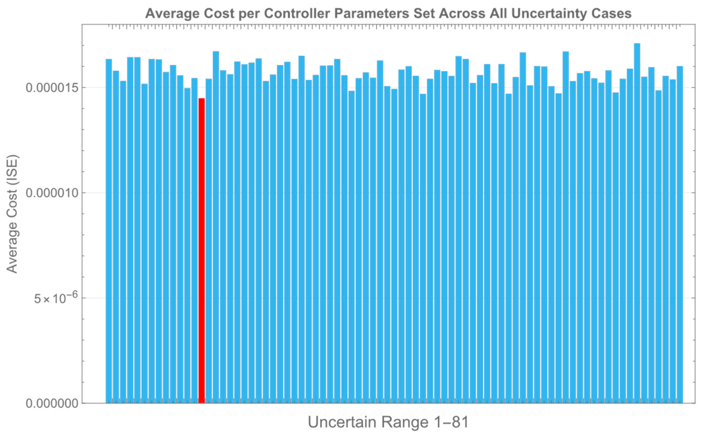
The best cost obtained for each of the 81 combinations of the uncertain parameters is illustrated in Figure 3, while the average cost corresponding to each set of controller parameters across all uncertainty realizations (see Figure 4, blue lines), along with the optimal value, is shown in Figure 4 (red line). The steps of the algorithm are presented in Figure 5.
It is important to point out that the execution time of the totalalgorithm, using 10 particles and evaluating 81 different cases of uncertain parameters, ranges between 18 and 20 min. This measurement was obtained using Amazon Web Services (AWS) an Amazon EC2 r7a.48xlarge instance, from Europe (Frankfurt) region and Local Zone eu-central-1, which provides 192 vCPUs, 1536 GiB of memory, and up to 50 Gbps of enhanced networking.

4.4. Modification to the Initialization Bounds of the PSO Algorithm

Here, a modified version of the PSO algorithm is developed. The PSO algorithm is modified as follows. After the first initial random choice of the first particle in the first stability region, using Algorithm 1, the rest of the stability regions are recalculated in order to find more suitable regions. After this manipulation, the new regions are set as bounds to the PSO algorithm. The new bounds are computed to be
I = 0 , 0.5 × 0 , 5 × 0 , 1 × 0 , 3 10 6 × 0 , 1 .
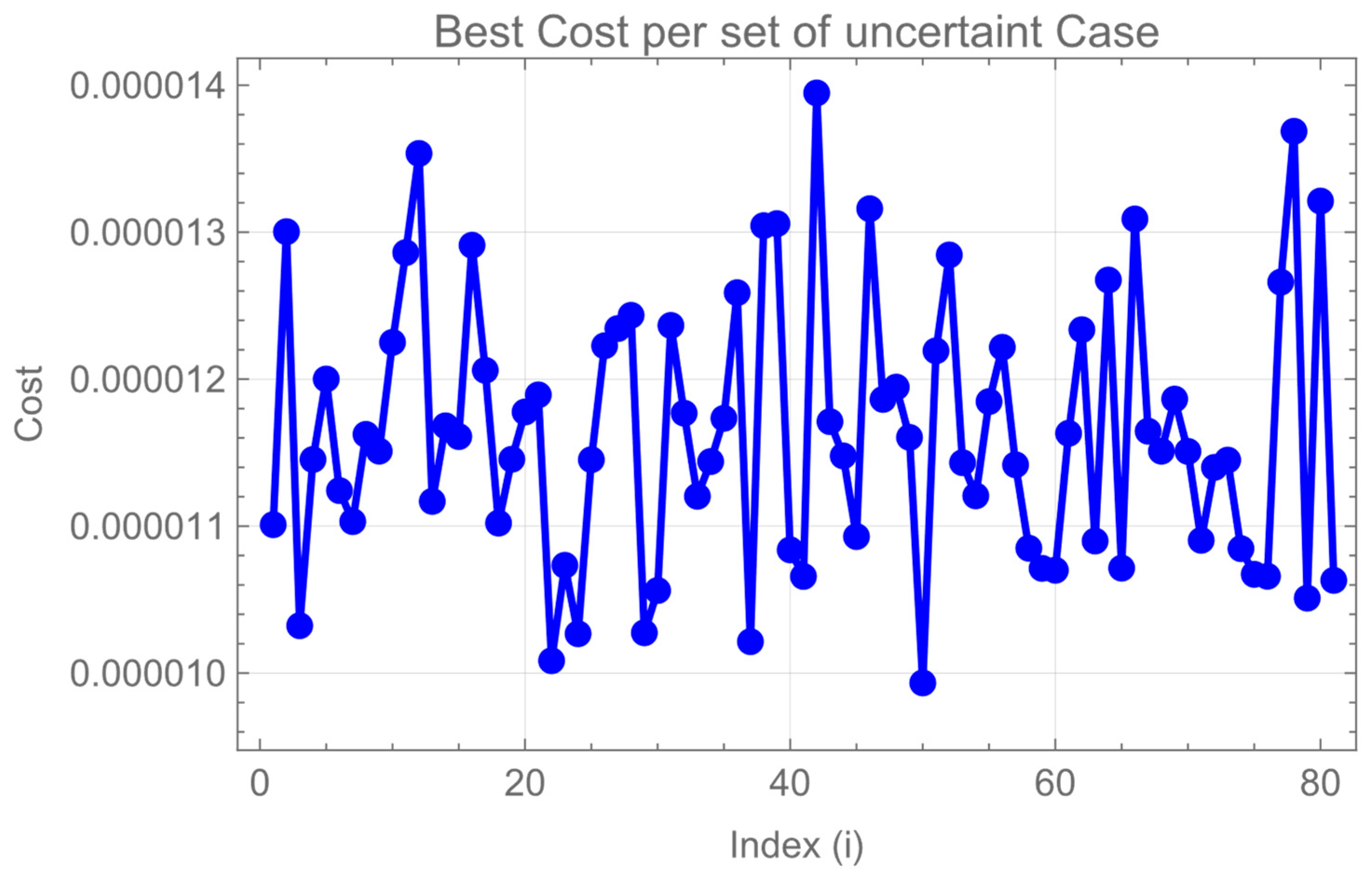
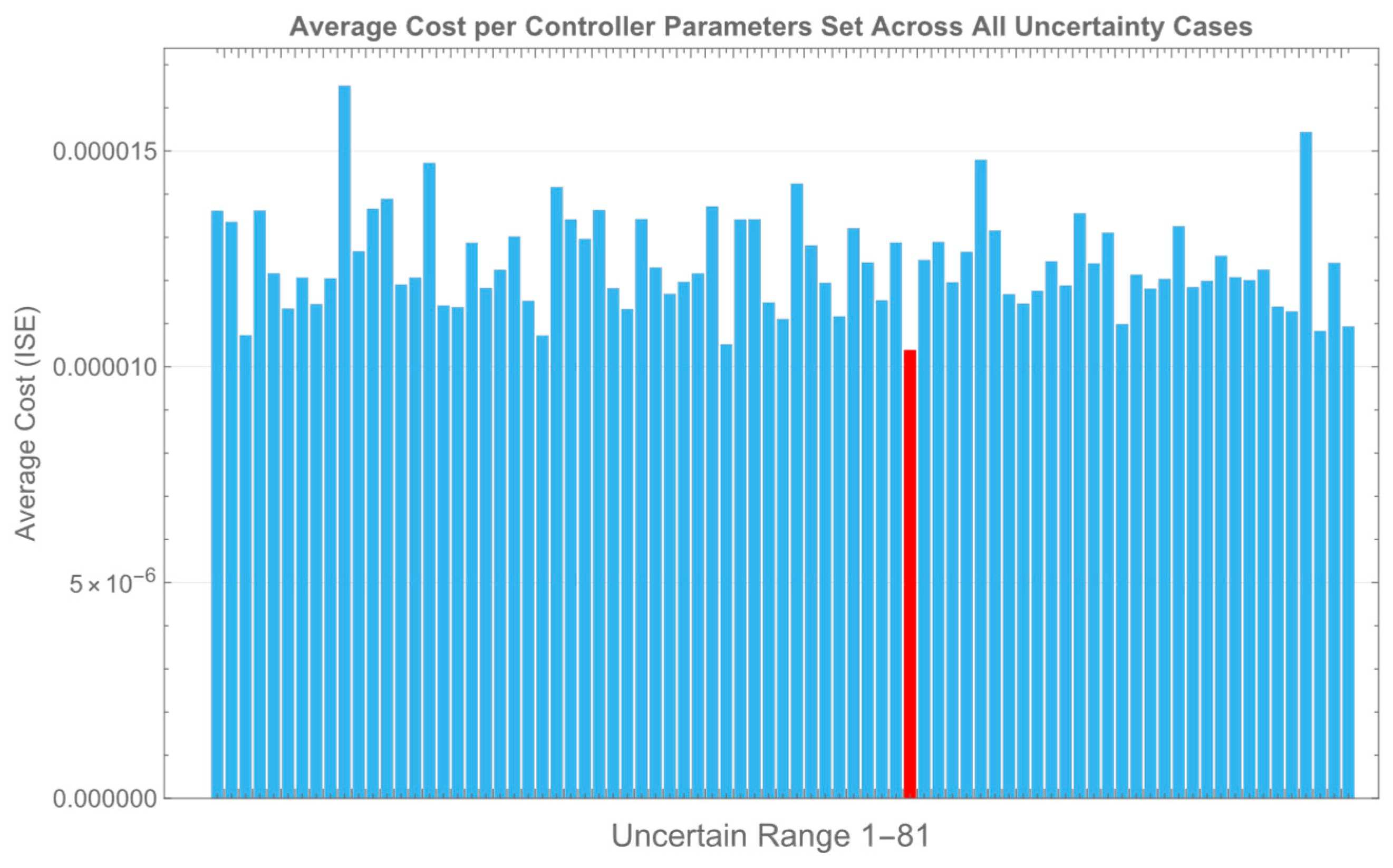
Figure 6 illustrates the minimum cost achieved for each of the 81 distinct combinations of the uncertain parameters. In contrast, Figure 7 depicts the average cost associated with each candidate set of the controller parameters, evaluated across all 81 uncertainty realizations. To compute these averages, each of the 81 best-performing controller parameter sets—identified from the initial evaluations—was subsequently tested over the entire uncertainty domain, comprising 6561 simulations in total. The controller configuration yielding the lowest average cost across this full domain (see Figure 7, blue lines) was then selected as the optimal solution (see Figure 7, red line).

5. Simulation Results

Using the reference signal e t t ( d 1 = 2 , d 2 = 1 ), the controller parameters are computed to be
f 1 = 0 , f 2 = 192.023 , f 3 = 20.6716 , f 4 = 23.60723 , f 5 = 12.2377 , f 6 = 0.0000023109 .
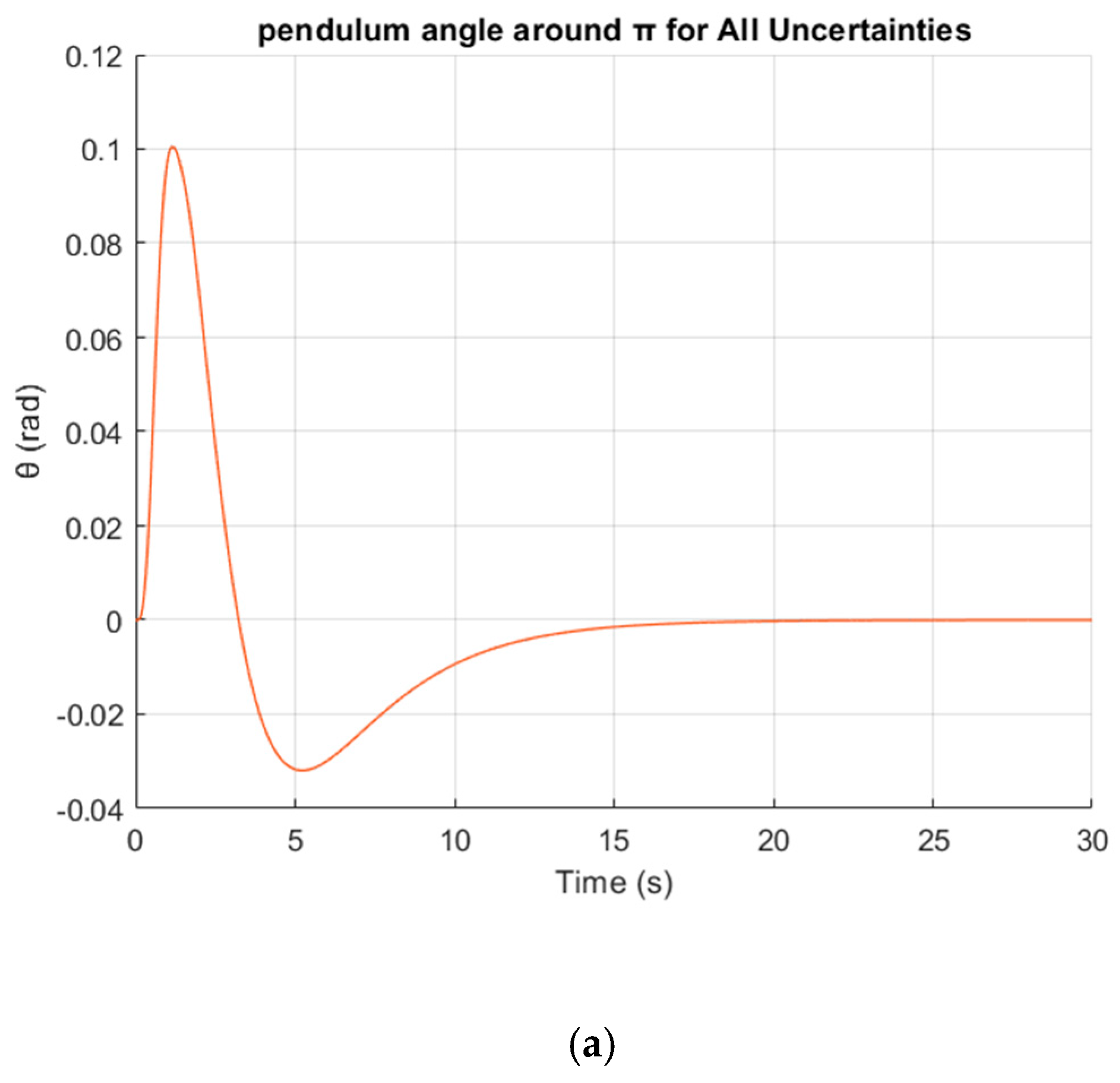
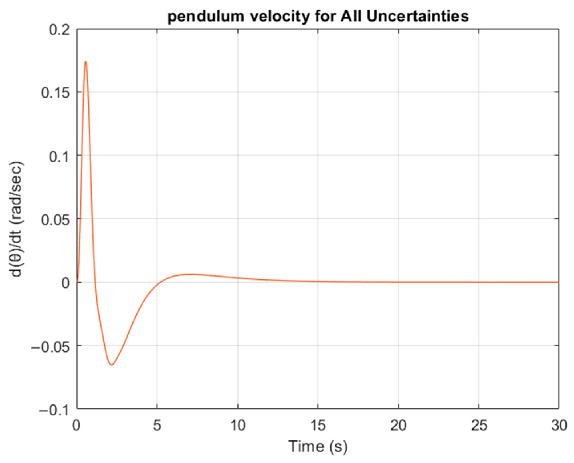
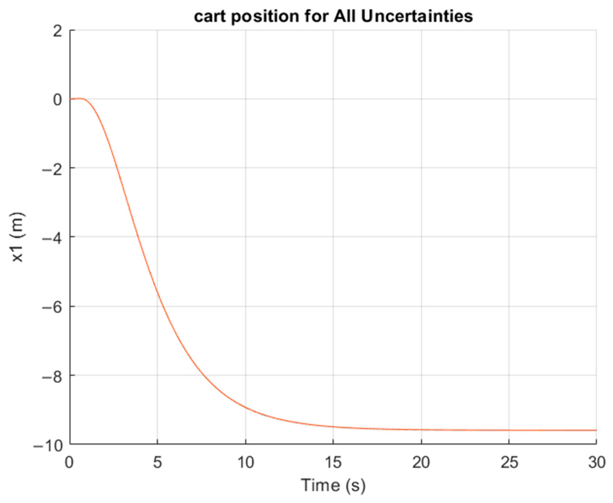
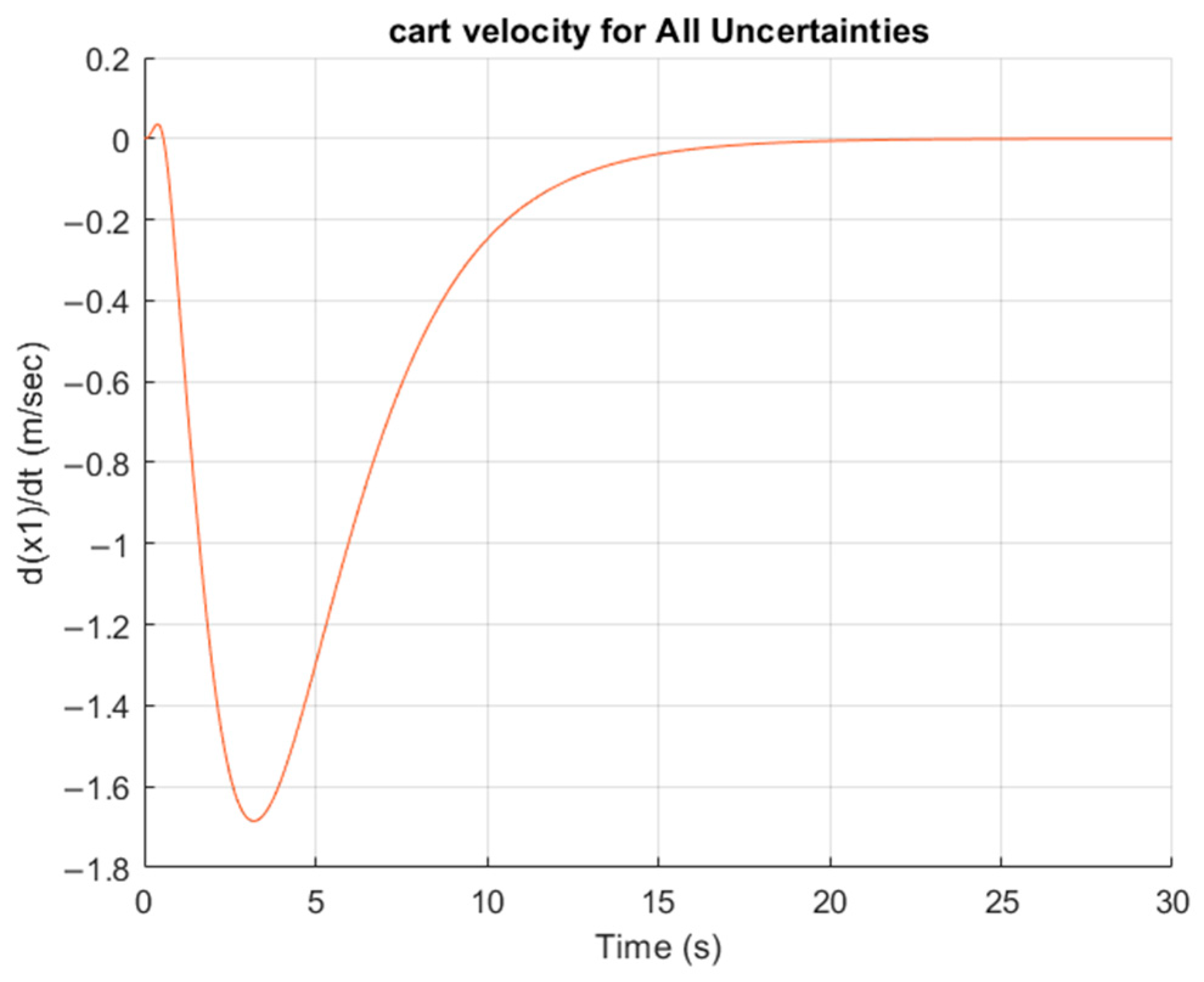
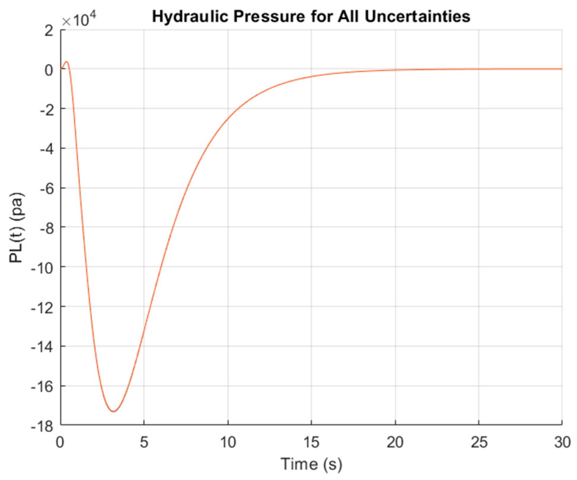
The simulation results examine a comprehensive set of different combinations of the uncertainty vector parameters, using Monte Carlo simulation. Each uncertain parameter was varied according to the formula q i = q i , m i n + q i , m a x q i , m i n r a n d ( ) ( i = 1 , 2 , 3 , 4 ) , where q i , m a x ,   q i , m i x are the max and min values of the uncertain q i as characterized by the domain Q , and r a n d ( ) generates a uniformly distributed random number in the interval ( 0 ,   1 ) . A total of 100 simulations were conducted, each with a unique set of perturbed parameter values. This way, a broad spectrum of potential system values is captured. Each combination represents a unique set of uncertain parameters that could arise due to changes in the operating conditions or external environmental disturbances. By systematically varying these parameters, the simulations provide a robust assessment of the controller’s performance across a wide range of scenarios, thereby evaluating its stability, responsiveness, and overall effectiveness under diverse and uncertain operating conditions. This thorough approach ensures that the controller design is resilient to parameter fluctuations, enhancing reliability in real-world applications. From Figure 8, Figure 9, Figure 10, Figure 11 and Figure 12, it is observed that when the system is disturbed from its initial position and actuated with the reference signal, the hydraulic actuator successfully returns the pendulum around to its initial position in approximately 16 s (see Figure 8).
It is important to highlight that, due to the structure of the selected system, the output variable—specifically the pendulum angle around the upright position—is highly sensitive to small deviations from its nominal position and rapid actuation signals from the hydraulic system. As shown in Figure 8, the performance of the proposed robust controller ensures reliable tracking and guarantees the stability of the closed-loop system despite these challenges.

6. Comparison Study

To evaluate the effectiveness of the proposed controller, its performance was compared with several well-established control strategies. These include an auto-tuned Proportional–Integral (PI) controller [51], a Model Predictive Controller (MPC) [52], an H state-feedback controller [53], and an LMI-based state-feedback controller with integral axion [54]. All the simulations were performed in MATLAB (R2024b) using a linear model with nominal parameter values: K q , n o m   = 1.02 ,   C l e a k , n o m = 0 ,   K c , n o m = 1.65 10 11 , β n o m = 689 10 6 ) [18]. Monte Carlo simulations were employed to evaluate the effects of system uncertainties and parameter variability. Each uncertain parameter was varied according to the formula q i = q i , m i n + q i , m a x q i , m i n r a n d ( ) v a r i a t i o n   ( i = 1 , 2 , 3 , 4 ) , where q i , m a x ,   q i , m i x   are the max and min values of the uncertain q i as characterized by the domain Q , v a r i a t i o n represents the percentage deviation from the nominal value, and r a n d ( ) generates a uniformly distributed random number in the interval ( 0 ,   1 ) . A total of 100 simulations were conducted, each with a unique set of perturbed parameter values. Table 2 presents a detailed comparison of the controller performance under v a r i a t i o n = 5 % , Table 3 presents a detailed comparison of the controller performance under v a r i a t i o n = 20 % , and Table 4 presents a detailed comparison of the controller performance under v a r i a t i o n = 100 % .
Based on the results of Table 2, Table 3 and Table 4, it is important to mention that comparative study across varying levels of uncertainty (5%, 20%, and 100%) reveals distinct trends in the controller performance. The proposed controller offers excellent robustness, maintaining consistent performance across all uncertainty levels, albeit with moderate dynamic response. The H controller is very fast and accurate but begins to degrade under extreme uncertainties. The MPC and LMI-based controllers are efficient under mild uncertainty but fail completely at 100%, limiting their practical robustness. Finally, the PI controller is the least efficient, with slow dynamics and inconsistent performance. Furthermore, the proposed controller is the only one that indicates visual identical performance over the whole range of the uncertain domain (see Figure 8).

7. Conclusions and Future Research Directions

This paper focuses on safe artificial intelligence algorithms for controlling the angle of an inverted pendulum mounted on a cart. The hydraulic actuator used to control the cart’s motion performs effectively in an unstable, uncertain environment. The combination of a robust Hurwitz invariance finite-step algorithm with a Particle Swarm Optimization (PSO) algorithm ensures satisfactory system performance across a wide range of uncertainties.
The controller was validated for the linear system and tested for pendulum angle variations within the range of −9° to +9°. Within this interval, the linear approximation remains accurate, and the control performance was shown to be robust and effective in maintaining stability and achieving desired tracking objectives.
The performance of the proposed controller was compared with Model Predictive Control (MPC) and classical PID controllers. While the latter approaches offer acceptable performance, their robustness does not exceed 50% of the total uncertainty domain. In contrast, the proposed robust controller performs satisfactorily across nearly the entire uncertainty domain, with percentage variations exceeding 80% in each dimension.
Future research will focus on implementing the proposed control method in a real-world experimental setup involving an industrial hydraulic actuator and an inverted pendulum. This will allow the evaluation of the controller’s robustness and effectiveness under real nonlinearities, actuator dynamics, and external disturbances.
In addition, further research directions include extending the control design to incorporate the full nonlinear dynamics of hydraulic systems, such as valve behavior, and the nonlinear dynamics of the inverted pendulum.
The methodology will also be generalized to multi-input multi-output (MIMO) systems, where coupling effects and increased complexity pose additional challenges. Although direct comparisons with other systems are not straightforward due to the limited number of studies addressing hydraulic actuation in inverted pendulum configurations, future work will aim to benchmark the proposed approach against available control strategies in related domains using experimental platforms and broader validation metrics.
Future research directions include evaluating the proposed benchmark using state-of-the-art robust tracking methodologies, in line with current advancements in the field. Notably, recent progress in adaptive motion control of electro-hydraulic servo systems with appointed-time performance, as well as neural adaptive dynamic surface control techniques with guaranteed transient response, warrants further investigation (see [55,56,57,58]). Future work will emphasize the design of robust controllers using s (LMI), as well as the development of delay-resilient and adaptive or learning-based control strategies (e.g., [59,60]). Particular attention will be given to adaptive control methods that ensure finite-time attitude tracking in the presence of unknown disturbances and maintain safe tracking performance under full-state constraints and input saturation (e.g., [61,62]). In addition, predictor–observer control approaches and active disturbance rejection techniques accounting for time-varying delays and external disturbances will be further investigated (e.g., [63,64]).

Author Contributions

Software, M.T.; Formal analysis, M.G.S., N.D.K. and F.N.K. All authors have read and agreed to the published version of the manuscript.

Funding

This research received no external funding.

Institutional Review Board Statement

Not applicable.

Informed Consent Statement

Not applicable.

Data Availability Statement

Data is contained within the article.

Conflicts of Interest

The authors declare no conflict of interest.

References

  1. Skarpetis, M.G.; Koumboulis, F.N. Robust Controller Design for Uncertain Hydraulic Actuators Using Sine-Cosine Op-timization Algorithms. In Automatic Control of Hydraulic Systems; Nova Science Publishers: Hauppauge, NY, USA, 2023; ISBN 979-8-88697-619-9. [Google Scholar]
  2. Skarpetis, M.G.; Koumboulis, F.N.; Tzamtziou, K.A.; Michopoulos, P. A Robust Control Scheme for an Experimental Hydraulic System. In Proceedings of the 2021 International Conference on Engineering and Emerging Technologies (ICEET), Istanbul, Turkey, 27–28 October 2021; pp. 1–6. [Google Scholar]
  3. Skarpetis, M.G.; Koumboulis, F.N. Robust stabilizability algorithms with application to force control of a hydraulic actuator. In Proceedings of the 2015 6th International Conference on Modeling, Simulation, and Applied Optimization (ICMSAO), Istanbul, Turkey, 27–29 May 2015; pp. 1–6. [Google Scholar]
  4. Skarpetis, M.G.; Koumboulis, F.N.; Ntellis, A.S. A Heuristic Control Algorithm for Robust Internal Model Control with Arbitrary Reference Model. In Informatics in Control Automation and Robotics; Lecture Notes in Electrical Engineering; Springer: Cham, Switzerland, 2014; Volume 283. [Google Scholar]
  5. Skarpetis, M.G.; Koumboulis, F.N.; Ntellis, A.S. Robust Position Tracking for a Hydraulic Servo System. In Proceedings of the 22nd Mediterranean Conference on Control and Automation, Palermo, Italy, 16–19 June 2014; pp. 1553–1558. [Google Scholar] [CrossRef]
  6. Pesterev, A.V.; Morozov, Y.V. Stabilization of a Cart with Inverted Pendulum. Autom. Remote Control 2022, 83, 78–91. [Google Scholar] [CrossRef]
  7. Blondin, M.J.; Pardalos, P.M. A Holistic Optimization Approach for Inverted Cart-Pendulum Control Tuning. Soft Comput. 2020, 24, 4343–4359. [Google Scholar] [CrossRef]
  8. Maraslidis, G.S.; Kottas, T.L.; Tsipouras, M.G.; Fragulis, G.F. Design of a Fuzzy Logic Controller for the Double Pendulum Inverted on a Cart. Information 2022, 13, 379. [Google Scholar] [CrossRef]
  9. Chiasson, J. An Introduction to System Modeling and Control; John Wiley & Sons: Hoboken, NJ, USA, 2022. [Google Scholar]
  10. Rithirun, C.; Charean, A.; Sawaengsinkasikit, W. Comparison Between PID Control and Fuzzy PID Control on Invert Pendulum System. In Proceedings of the 2021 9th International Electrical Engineering Congress (iEECON), Pattaya, Thailand, 10–12 March 2021; pp. 337–340. [Google Scholar]
  11. Hasan, M.; Saha, C.; Rahman, M.; Sarker, R.I.; Aditya, S.K. Balancing of an Inverted Pendulum Using PD Controller. Dhaka Univ. J. Sci. 2012, 60, 115–120. [Google Scholar] [CrossRef]
  12. Brumand-Poor, F.; Kauderer, L.; Matthiesen, G.; Schmitz, K. Application of Deep Reinforcement Learning Control of an Inverted Hydraulic Pendulum. Int. J. Fluid Power 2023, 24, 393–418. [Google Scholar] [CrossRef]
  13. White, W.N.; Fales, R.C. Control of a Double Inverted Pendulum with Hydraulic Actuation. In Proceedings of the 1999 American Control Conference, San Diego, CA, USA, 2–4 June 1999; IEEE: Piscataway, NJ, USA, 1999. [Google Scholar]
  14. Žilić, T.; Pavković, D.; Zorc, D. Modeling and Control of A Pneumatically Actuated Inverted Pendulum. ISA Trans. 2009, 48, 327–335. [Google Scholar] [CrossRef] [PubMed]
  15. Ding, G.; Bian, Y.; Yang, M. Design and Application of Hydraulic Inverted Pendulum. In Proceedings of the International Conference on Advances in Construction Machinery and Vehicle Engineering, Shanghai, China, 13–16 October 2023; Springer: Berlin/Heidelberg, Germany, 2023. [Google Scholar]
  16. Cordasco, V.; Di Maggio, A. Modeling, Design, and Control of a Cart Inverted Pendulum with Electrical and Pneumatic Actuation. Master’s Thesis, Politecnico di Torino, Turin, Italy, 2020. [Google Scholar]
  17. Merritt, H.E. Hydraulic Control Systems; John Wiley & Sons: Hoboken, NJ, USA, 1967. [Google Scholar]
  18. Karpenko, M.; Sepehri, N. Fault-tolerant control of a servohydraulic positioning system with crossport leakage. IEEE Trans. Control Syst. Technol. 2005, 13, 155–161. [Google Scholar] [CrossRef]
  19. Skarpetis, M.G.; Koumboulis, F.N. A Two-Step Design for Robust Input-Output Decoupling of a Class of Uncertain and Linear Parameter Dependent Systems. In Proceedings of the 2024 32nd Mediterranean Conference on Control and Automation (MED), Crete, Greece, 11–14 June 2024; pp. 884–890. [Google Scholar]
  20. Mohmmed, J.H.; Hassan, A.K.; Ali, M.; Kokz, S.A.; Mosa, M.H.; Kareem, A.; Zainulabdeen, A.A.; Feng, Z. Design of Uncertain Displacement Controlled Velocity Control System for Hydraulic Actuator. Heliyon 2024, 10, e26223. [Google Scholar] [CrossRef]
  21. Mohanty, A.; Yao, B. Indirect Adaptive Robust Control of Hydraulic Manipulators with Accurate Parameter Estimates. IEEE Trans. Control. Syst. Technol. 2010, 19, 567–575. [Google Scholar] [CrossRef]
  22. Hejrati, M.; Mattila, J. Impact-Resilient Orchestrated Robust Controller for Heavy-Duty Hydraulic Manipulators. IEEE/ASME Trans. Mechatron. 2025, 1–12. [Google Scholar] [CrossRef]
  23. Cheng, G.; Pan, S. Nonlinear Adaptive Robust Control of Single-Rod Electro-Hydraulic Actuator with Unknown Nonlinear Parameters Control Systems Technology. IEEE Trans. 2008, 16, 434–445. [Google Scholar]
  24. Niksefat, N.; Sepehri, N. Designing robust force control of hydraulic actuators despite system and environmental uncertainties. Control. Syst. Mag. IEEE 2001, 21, 66–77. [Google Scholar]
  25. Yao, B.; Bu, F.; Reedy, J.; Chiu, G.-C. Adaptive robust motion control of single-rod hydraulic actuators: Theory and experiments. IEEE/ASME Trans. Mechatronics 2000, 5, 79–91. [Google Scholar] [CrossRef]
  26. Jerouane, M.; Sepehri, N.; Lamnabhi-Lagarrigue, F.; Abou, S.C. Design and Experimental Evaluation of Robust Variable Structure Control for Hydraulic Actuators. In Proceedings of the 5th Asian Control Conference, Melbourne, Australia, 20–23 July 2004; Volume 3, pp. 1982–1990. [Google Scholar]
  27. Kliffken, M.G. Robust Sampled-Data Control of Hydraulic Flight Control Actuators. In Proceedings of the 5th Scandinavian International Conference on Fluid Power, Linköping, Sweden, 28–30 May 1997. [Google Scholar]
  28. Koumboulis, F.N.; Skarpetis, M.G.; Tzamtzi, M.P. Robust PI Controllers for Command Following with Application to an Electropneumatic Actuator. In Proceedings of the 2006 14th Mediterranean Conference on Control and Automation, Ancona, Spain, 28–30 June 2006; pp. 1–6. [Google Scholar]
  29. Koumboulis, F.N.; Skarpetis, M.G.; Mertzios, B.G. Robust Regional Stabilization of an Electropneumatic Actuator. IEEE Proc.-Control Theory Appl. 1998, 145, 226–230. [Google Scholar] [CrossRef]
  30. Skarpetis, M.G.; Koumboulis, F.N.; Ntellis, A.S.; Sarris, A. Robust controller design for active hydraulic suspension. In Proceedings of the 2007 IEEE Conference on Emerging Technologies & Factory Automation (EFTA 2007), Patras, Greece, 5–28 September 2007; pp. 1433–1436. [Google Scholar]
  31. Skarpetis, M.G.; Koumboulis, F.N.; Tzamtzi, M. Robust Control Techniques for Hydraulic Actuators. In Proceedings of the 15th Mediterranean Conference on Control and Automation, Athens, Greece, 27–29 July 2007; pp. 1–6. [Google Scholar]
  32. Wei, K.B.; Barmish, R. Making a polynomial Hurwitz invariant by choice of feedback gain. Int. J. Control 1989, 50, 1025–1038. [Google Scholar] [CrossRef]
  33. Wei, K. Stabilization of Linear Time-Invariant Interval Systems Via Constant State Feedback Control. IEEE Trans. Autom. Control 1994, 39, 22–32. [Google Scholar] [CrossRef]
  34. Koumboulis, F.; Skarpetis, M. Robust Triangular Decoupling with Application to 4ws Cars. IEEE Trans. Autom. Control 2000, 45, 344–352. [Google Scholar] [CrossRef]
  35. Koumboulis, F.; Skarpetis, M. Input-Output Decoupling for Linear Systems with Nonlinear Uncertain Structure. J. Frankl. Inst. 1996, 333, 593–624. [Google Scholar] [CrossRef]
  36. Koumboulis, F.N.; Skarpetis, M.G. Robust Disturbance Rejection for Left-Invertible Linear Systems With Nonlinear-Uncertain Structure. J. Dyn. Syst. Meas. Control 1999, 121, 218–225. [Google Scholar] [CrossRef]
  37. Skarpetis, M.G.; Koumboulis, F.N. Solving Robust Control Problems Using Robust Pole Placement in a Disk. In Proceedings of the 14th IEEE International Conference on Emerging Technologies and Factory Automation (ETFA), Palma de Mallorca, Spain, 22–25 September 2009. [Google Scholar]
  38. Yang, S.; Yew-Soon, O.; Jin, Y. (Eds.) Evolutionary Computation in Dynamic and Uncertain Environments; Springer: Berlin/Heidelberg, Germany, 2007; Volume 51. [Google Scholar]
  39. Devarapalli, R.; Bhattacharyya, B.; Sinha, N.K. An Intelligent EGWO-SCA-CS Algorithm for PSS Parameter Tuning Under System Uncertainties. Int. J. Intell. Syst. 2020, 35, 1520–1569. [Google Scholar] [CrossRef]
  40. Geng, N.; Chen, Z.; Nguyen, Q.A.; Gong, D. Particle Swarm Optimization Algorithm For The Optimization Of Rescue Task Allocation With Uncertain Time Constraints. Complex Intell. Syst. 2021, 7, 873–890. [Google Scholar] [CrossRef]
  41. Kennedy, J.; Eberhart, R.C. Particle Swarm Optimization. In Proceedings of IEEE International Conference on Neural Networks; IEEE Press: Piscataway, NJ, USA, 1995; pp. 1942–1948. [Google Scholar]
  42. Kim, T.-H.; Maruta, I.; Sugie, T. Robust PID Controller Tuning Based On The Constrained Particle Swarm Optimization. Automatica 2008, 44, 1104–1110. [Google Scholar] [CrossRef]
  43. Xu, G.; Yu, G. On Convergence Analysis of Particle Swarm Optimization Algorithm. J. Comput. Appl. Math. 2018, 343, 1–13. [Google Scholar]
  44. Poli, R.; Broomhead, D. Exact Analysis of The Sampling Distribution for the Canonical Particle Swarm Optimiser and its Convergence During Stagnation. In Proceedings of the 9th Annual Conference on Genetic and Evolutionary Computation (GECCO ‘07), London, UK, 7–11 July 2007; pp. 134–141. [Google Scholar]
  45. Erwin, K.; Engelbrecht, A. Control Parameter Sensitivity Analysis of the Multi-Guide Particle Swarm Optimization Algorithm. In Proceedings of the GECCO ‘19: Genetic and Evolutionary Computation Conference, Prague, Czechia, 13–17 July 2019; pp. 22–29. [Google Scholar]
  46. Cleghorn, C.W. Particle Swarm Optimization: Understanding Order-2 Stability Guarantees. In Applications of Evolutionary Computation; EvoApplications 2019; Kaufmann, P., Castillo, P., Eds.; Springer: Cham, Switzerland, 2019; Volume 11454, pp. 534–549, Lecture Notes in Computer Science. [Google Scholar]
  47. Clerc, M.; Kennedy, J. The Particle Swarm: Explosion, Stability, and Convergence in a Multi-Dimensional Complex Space. IEEE Trans. Evol. Comput. 2002, 6, 58–73. [Google Scholar] [CrossRef]
  48. Nigatu, D.T.; Dinka, T.G.; Tilahun, S.L. Convergence Analysis Of Particle Swarm Optimization Algorithms For Different Constriction Factors. Front. Appl. Math. Stat. 2024, 10, 1304268. [Google Scholar] [CrossRef]
  49. Zhang, Y.; Qiao, F.; Lu, J.; Wang, L.; Wu, Q. Performance Criteria Research on PSO-PID Control Systems. In Proceedings of the 2010 International Conference on Intelligent Computing and Cognitive Informatics, Kuala Lumpur, Malaysia, 22–23 June 2010; pp. 316–320. [Google Scholar]
  50. Hussein, A.M.; Alomari, S.A.; Almomani, M.H.; Abu Zitar, R.; Migdady, H.; Smerat, A.; Snasel, V.; Abualigah, L. A Hybrid PSO-GCRA Framework for Optimizing Control Systems Performance. Int. J. Robot. Control Syst. 2025, 5, 459–478. [Google Scholar] [CrossRef]
  51. Gade, S.; Shendage, S.B.; Mahadev, U. MATLAB Based Response of Systems Using Auto Tune PID Controller. Int. J. Emerg. Technol. Adv. Eng. 2012, 2, 157–162. [Google Scholar]
  52. Augustine, M.T. Model Predictive Control Using MATLAB. arXiv 2023, arXiv:2309.00293. [Google Scholar]
  53. Gahinet, P. Structured H-Infinity Synthesis in MATLAB. IFAC Proc. Vol. 2011, 18, 1435–1440. [Google Scholar] [CrossRef]
  54. Ravat, A.K.; Amit, D.; Manish, T. LMI and YALMIP: Modeling and Optimization Toolbox in MATLAB. In Advances in VLSI, Communication, and Signal Processing; David, H., Ed.; Springer: Singapore, 2021; pp. 507–515. [Google Scholar]
  55. Zhou, Y.; Helian, B.; Chen, Z.; Yao, B. Adaptive Robust Constrained Motion Control of an Independent Metering Electro-Hydraulic System Considering Kinematic and Dynamic Constraints. IEEE Trans. Ind. Inform. 2025, 1–11. [Google Scholar] [CrossRef]
  56. Hua, C.; Zhou, J.; Zhang, B.; Zhang, Y.; Luo, X. Prescribed Performance Tracking Control For Electro-Hydraulic Systems With Output Constraints And Valve Dynamics Compensation. Nonlinear Dyn. 2025, 113, 13211–13223. [Google Scholar] [CrossRef]
  57. Liao, L.; Sang, Y.; Chen, T.; Jiang, L.; Liu, J. Research on Position Tracking Control Of Electro-Hydraulic Actuator System Combining Feedforward Inverse Model Controller And Exponential Functional Link Network Adaptive Controller. Proc. Inst. Mech. Eng. Part C J. Mech. Eng. Sci. 2025, 239, 643–658. [Google Scholar] [CrossRef]
  58. Chen, G.; Wu, W.; Yang, C.; Hu, H.; Zhang, J.; Shi, J.; Ma, Y. Practical Finite-Time Observ-er-Based Adaptive Backstepping Super-Twisting Sliding Mode Control for Deep-Sea Hydraulic Manipulator. IEEE Transac-Tions Ind. Electron. 2025. [Google Scholar] [CrossRef]
  59. Yang, X.; Ge, Y.; Zhu, W.; Deng, W.; Zhao, X.; Yao, J. Adaptive Motion Control for Electro-hydraulic Servo Systems with Appointed-Time Performance. IEEE/ASME Trans. Mechatron. 2025, 1–10. [Google Scholar] [CrossRef]
  60. Yang, X.; Deng, W.; Yao, J. Neural Adaptive Dynamic Surface Asymptotic Tracking Control of Hydraulic Manipulators With Guaranteed Transient Performance. IEEE Trans. Neural Netw. Learn. Syst. 2023, 34, 7339–7349. [Google Scholar] [CrossRef]
  61. Garanayak, C. Robust Adaptive Finite-Time Attitude Tracking with an unknown Inertia Matrix and Disturbance. In Proceedings of the 2024 IEEE 18th International Conference on Control & Automation (ICCA), Reykjavik, Iceland, 18–21 June 2024; pp. 270–275. [Google Scholar]
  62. Wu, X.; Ning, S.; Gao, Y.; Ma, J.; Qian, C.; Chen, Q. Prescribed Performance Asymptotic Tracking Control for Uncertain Non-Linear Systems With Full-State Constraints and Input Saturation. Int. J. Robust Nonlinear Control 2025, 35, 3028–3042. [Google Scholar] [CrossRef]
  63. Liu, C.; Yue, X.; Zhang, J.; Shi, K. Active Disturbance Rejection Control for Delayed Electromagnetic Docking of Spacecraft in Elliptical Orbits. IEEE Trans. Aerosp. Electron. Syst. 2022, 58, 2257–2268. [Google Scholar] [CrossRef]
  64. Lyu, B.; Liu, C.; Yue, X. Integrated Predictor–Observer Feedback Control for Vibration Mitigation of Large-Scale Spacecraft With Unbounded Input Time Delay. IEEE Trans. Aerosp. Electron. Syst. 2025, 61, 4561–4572. [Google Scholar] [CrossRef]
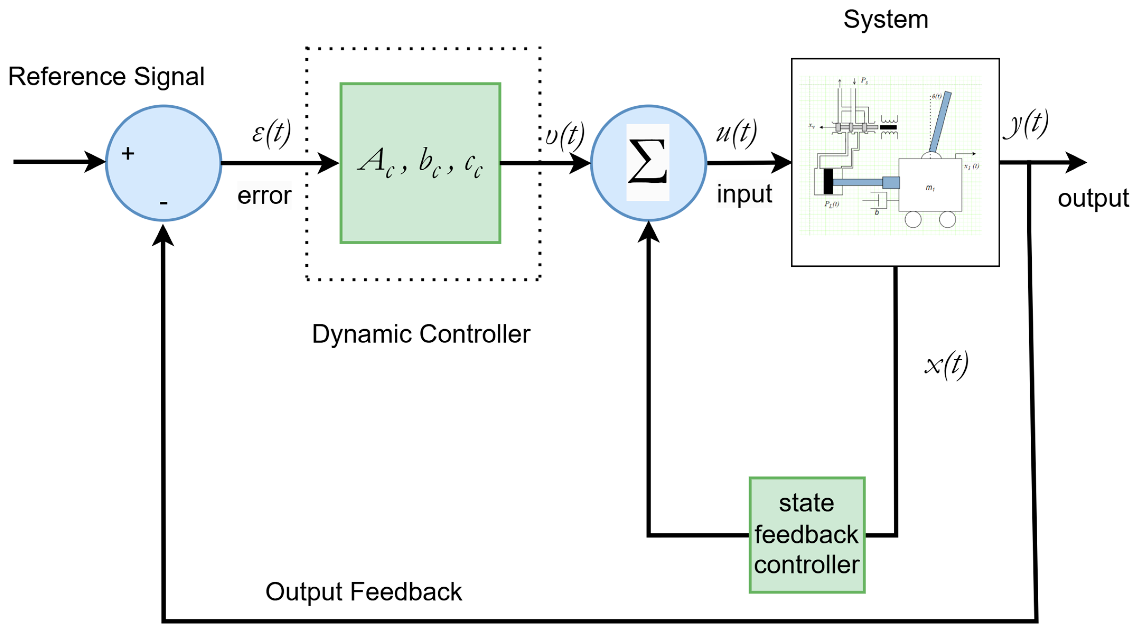
Figure 1. Closed-loop system block diagram.
Eng 06 00146 g001
Figure 2. Hydraulic inverted pendulum.
Eng 06 00146 g002
Figure 3. Best cost for 81 uncertain cases.
Eng 06 00146 g003
Figure 4. Average cost per controller parameters across all uncertainties—blue lines (red line denotes the best value).
Eng 06 00146 g004
Figure 5. PSO optimization flowchart.
Eng 06 00146 g005
Figure 6. Best cost for 81 uncertain cases after bound modification.
Eng 06 00146 g006
Figure 7. Average cost per controller parameters across all uncertainties after modification -blue lines (red line denotes the best value).
Eng 06 00146 g007
Figure 8. (a) Pendulum angle around π ; (b) pendulum angle around π (focus at 15.0196   s —each color represents a different set of uncertainties).
Eng 06 00146 g008aEng 06 00146 g008b
Figure 9. Pendulum velocity.
Eng 06 00146 g009
Figure 10. Cart position.
Eng 06 00146 g010
Figure 11. Cart velocity.
Eng 06 00146 g011
Figure 12. Hydraulic actuator pressure.
Eng 06 00146 g012
Table 1. Sensitivity analysis of key PSO parameters.
Number of ParticleCost Function ValueExecution Time (s)Deviation ( x i μ ) Squared Deviation
( x i μ ) 2
10 1.5472 × 10 5 12.309001 6.1612 × 10 7 3.7967 × 10 13
30 1.49697 × 10 5 36.276767 1.1382 × 10 7 1.2955 × 10 14
50 1.4397 × 10 5 61.4057274 4.5880 × 10 7 2.1055 × 10 13
70 1.50428 × 10 5 87.9554871 1.8692 × 10 7 3.4959 × 10 14
90 1.43939 × 10 5 113.6247406 4.6200 × 10 7 2.1344 × 10 10 13
Table 2. Comparison study for 5% variation.
MethodologyAverage Steady-State Error (Rad)Average Time to Peak ( s ) Average Steady-State Time
( s )
Average Rise Time (10% to 90%) to Peak ( s )
Proposed controller 0.000005 1.1604 16.0353 0.5602
MPC 0.000543 1.5118 1 6.3470 0.8574
PI 0.000019 2.2572 15.75825 1.2971
H state-feedback controller 0 0.7508 12.5348 0.3922
LMI-based state-feedback controller with integral axion 0 1.3262 8.4328 0.3910
Table 3. Comparison study for 20% uncertainty variation.
MethodologyAverage Steady-State ErrorAverage Time to Peak ( s ) Average Steady-State Time ( s ) Average Rise Time (10% to 90%) to Peak ( s )
Proposed controller 0.000005 1.1604 16.0380 0.5602
MPC 0.02710 1.4923 16.1496 0.8422
PI 0.000007 2.0912 15.85825 1.1862
H state-feedback controller 0 0.7508 13.6087 0.3892
LMI-based state-feedback controller with integral axion 0.000001 1.2701 8.5341 0.6160
Table 4. Comparison study for 100% uncertainty variation.
MethodologyAverage Steady-State ErrorAverage Time to Peak ( s ) Average Steady-State Time
( s )
Average Rise Time (10% to 90%) to Peak ( s )
Proposed controller 0.000005 1.1604 16.0441 0.5602
MPCThe controller does not provide robust performance across the full spectrum of system uncertainties.
PI 0.000015 1.6514 17.4608 0.9434
H state-feedback controller 0.00015 0.8099 21.023 0.4186
LMI-based state-feedback controller with integral axionThe controller does not provide robust performance across the full spectrum of system uncertainties.
Disclaimer/Publisher’s Note: The statements, opinions and data contained in all publications are solely those of the individual author(s) and contributor(s) and not of MDPI and/or the editor(s). MDPI and/or the editor(s) disclaim responsibility for any injury to people or property resulting from any ideas, methods, instructions or products referred to in the content.