
Mechanical Properties of Hybrid Structures Incorporating Nano-Silica and Basalt Fiber Pellets


Abstract
:1. Introduction
2. Experimental Program
2.1. Materials
2.2. Proportions and Mixing Procedues
2.3. Tests
3. Test Results and Discussion
3.1. Flowability
3.2. Compressive Strength
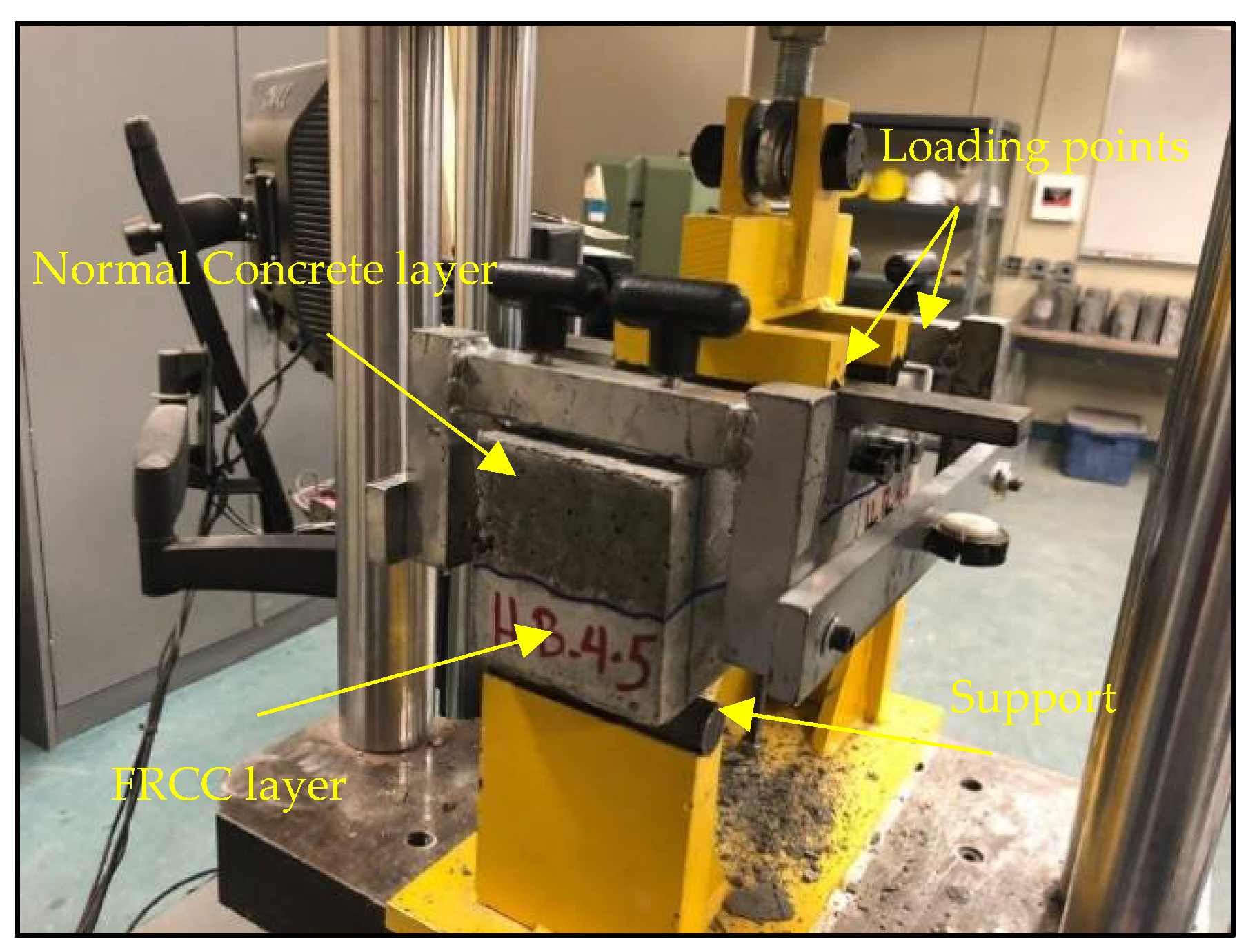
3.3. Flexural Strength and Toughness
3.4. Bond Strength
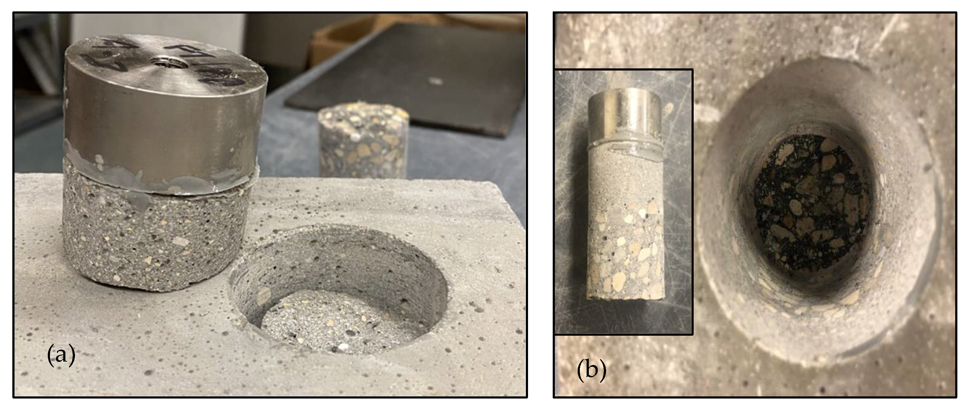
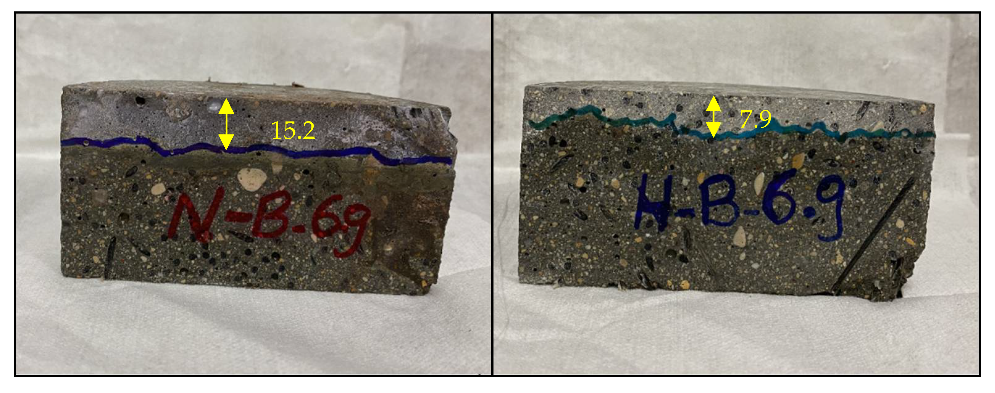
3.5. Penetrability
4. Conclusions
- The inclusion of SF in the H composites reduced the flowability, whereas the replacement of SFs by BF pellets at different dosages had less effect on the flowability and flow loss, which makes the BFRCC suitable for field applications in terms of the placement and finishability process.
- The results generally show that the early-age and later-age compressive strength of the H composites comprising different types and dosages of fibers markedly improved, as all values were above 55 MPa at seven days. Hence, the inherently slower rate of strength development of cementitious systems containing slag can be controlled by the addition of a small dosage (6%) of nano-silica.
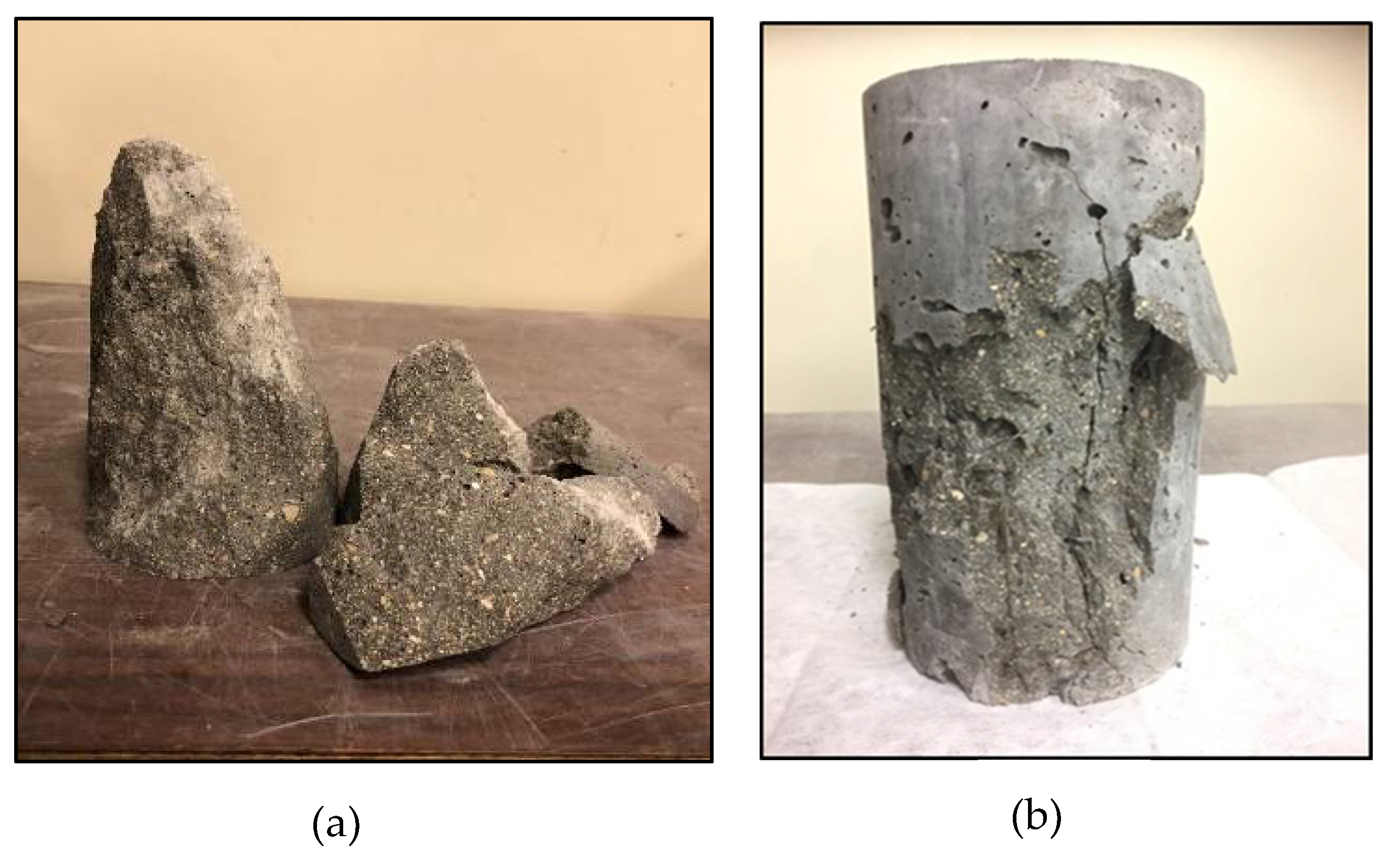
- Compared to the control mixtures without fibers, BFRCC mixtures with fibers yielded lower compressive strength, especially with higher dosages of BF pellets; however, the mode of failure considerably changed from brittle to ductile.
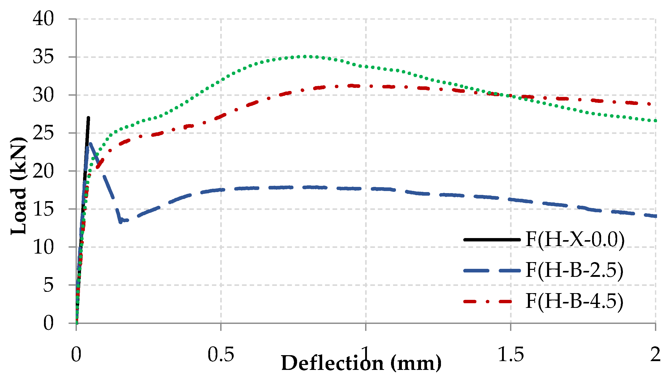
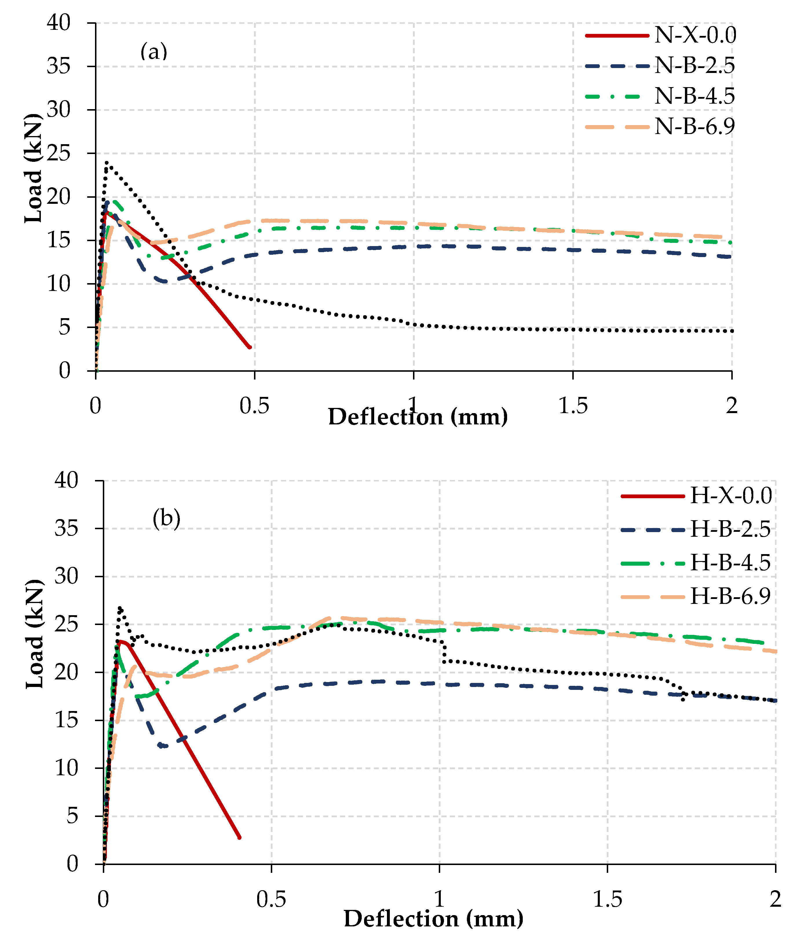
- The layered prisms reinforced with high dosages of BF pellets (H-B-4.5 and H-B-6.9) exhibited a pseudo strain-hardening process (ranging between 47 and 45 J), while the prisms reinforced with SF (H-S-1.0) showed a strain-softening behavior.
- Keeping the volume of BF pellets and SF constant (H-B-2.5 vs H-S-1.0) showed comparable post-cracking behavior.
- At a fixed fiber dosage, the incorporation of FRCC, as a layer in the tension side only, yielded comparable toughness and maintained acceptable post-peak performance to counterpart specimens comprising FRCC over the full depth. This notion has proven to be technically more efficient and economic than the common practice of adding the fibers over the whole cross-section.
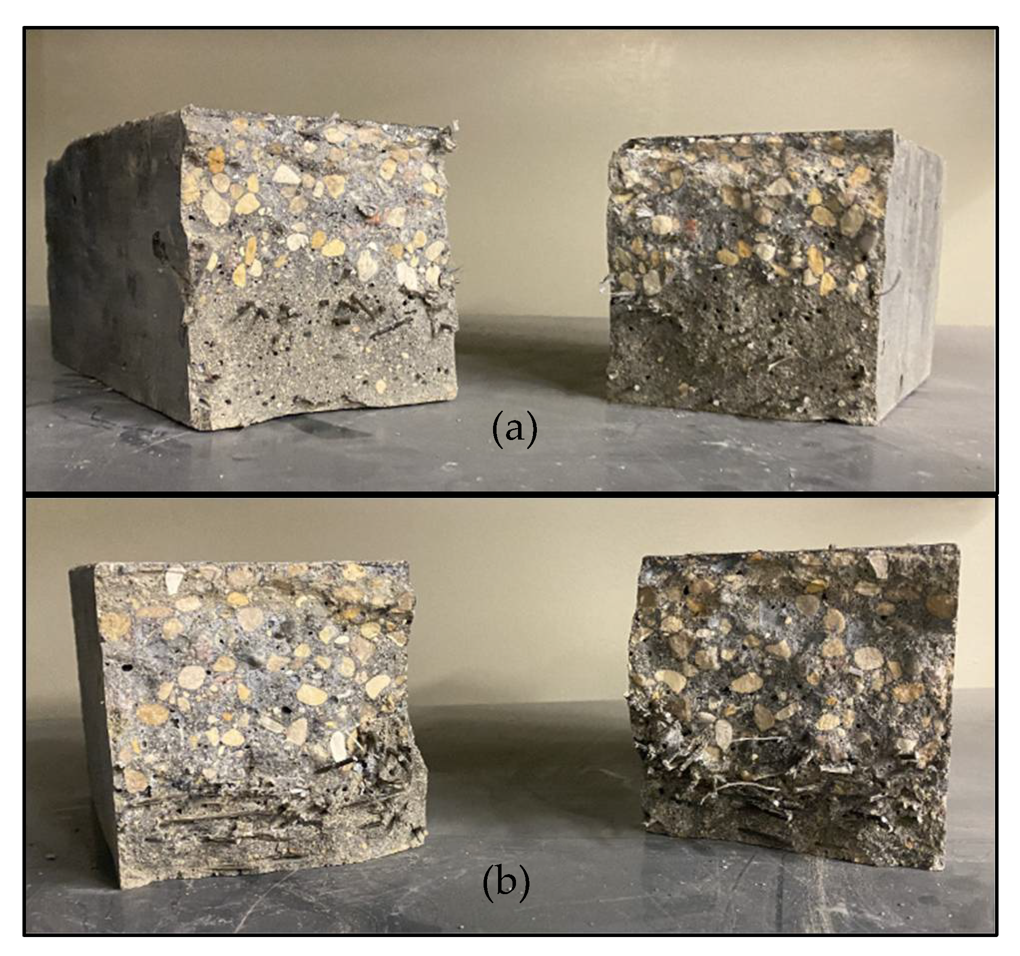
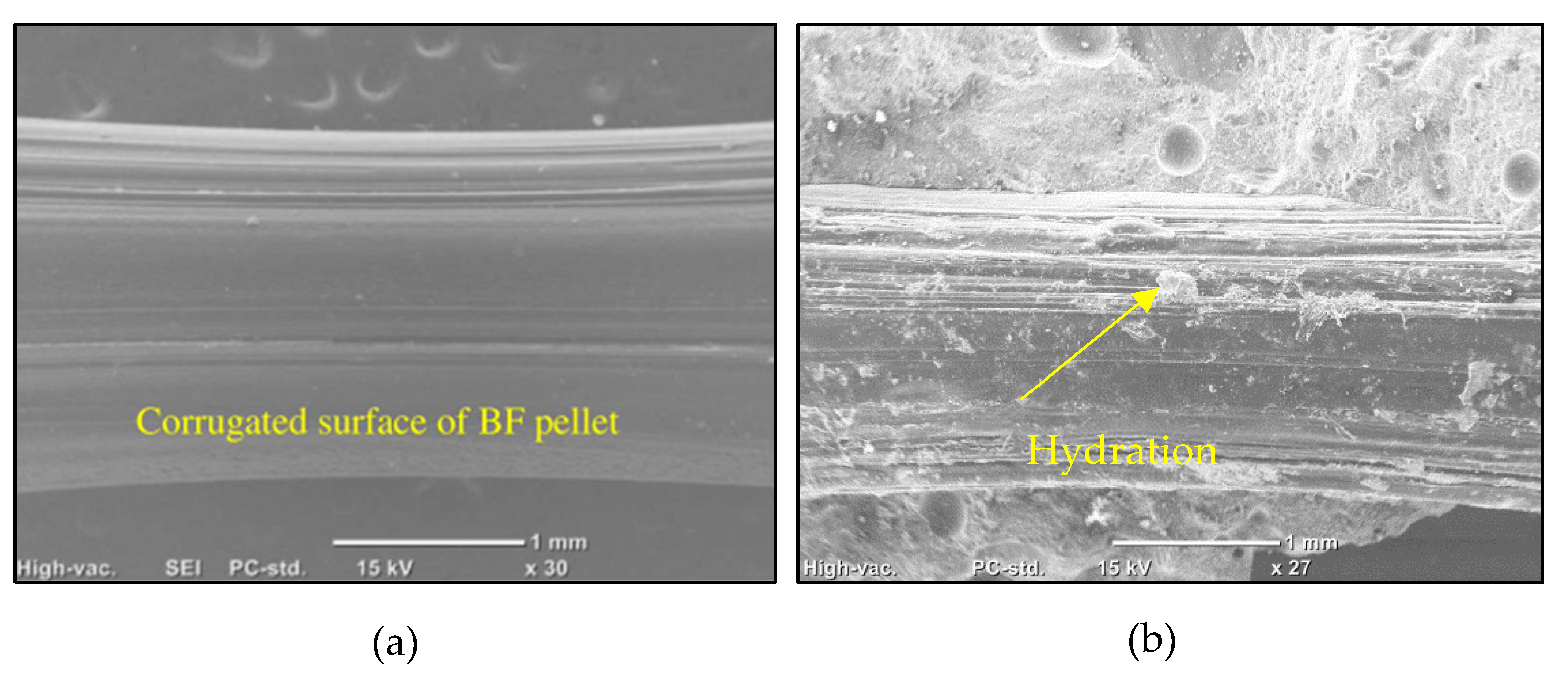
- The superior bonding of BF pellets with the cementitious matrix was one of the main reasons for such an enhanced post-cracking behavior compared to SF, which is promising to produce high strength and high ductility cementitious composites using non- metallic fibers.
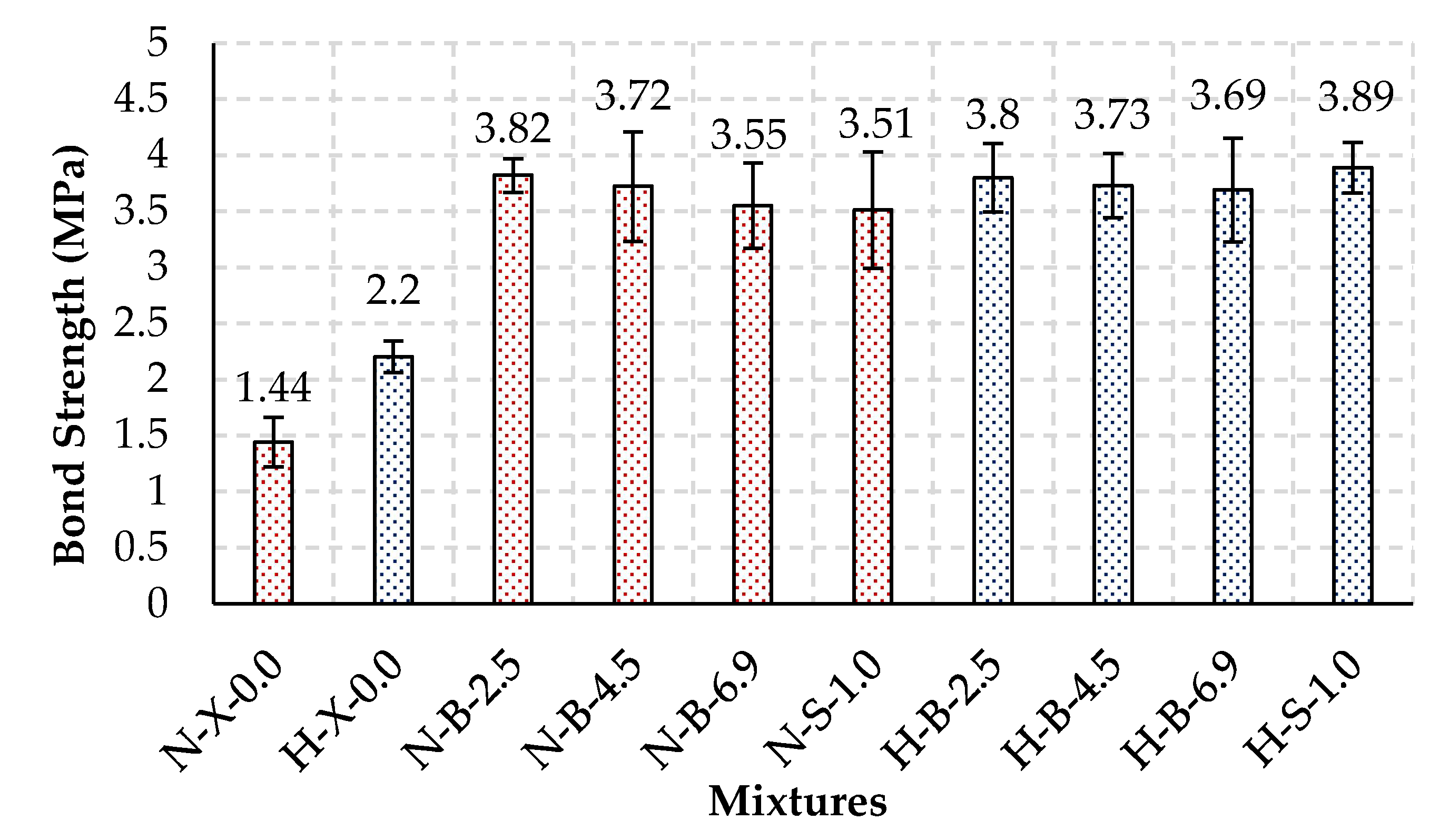
- In comparison to N-X-0.0 and H-X-0.0, the pull-off test results showed that the bond strength of all fibrous composites, despite the type or dosage of the fibers included, increased. In addition, the bond strength for the later specimens were quite similar since the failure of the specimens occurred in the base concrete.
- Compared to the control specimens without SCMs (N composites) and irrespective of the dosage of fibers, the passing charges of H composites were less than 1000 coulombs, which signified the synergistic effects of nano-silica and slag on densifying cementitious systems comprising different types of fibers and reducing their penetrability (as shown by the low penetration depth in the RCPT).
- Overall, the results showed the efficacy of developing a corrosion-free composite for improving the post-cracking behavior of specimens, as they successfully controlled the progress of cracks and behaved similarly to the samples cast with SF, which can be proposed as a promising solution for infrastructure applications such as bridge girders or overlays.
Author Contributions
Funding
Data Availability Statement
Acknowledgments
Conflicts of Interest
References
- Vasanelli, E.; Micelli, F.; Aiello, M.A.; Plizzari, G. Crack width prediction of FRC beams in short and long term bending condition. Mater. Struct. 2013, 47, 39–54. [Google Scholar] [CrossRef]
- Nes, L.G.; Øverli, J.A. Structural behaviour of layered beams with fibre-reinforced LWAC and normal density concrete. Mater. Struct. 2015, 49, 689–703. [Google Scholar] [CrossRef] [Green Version]
- Abousnina, R.; Alsalmi, H.I.; Manalo, A.; Allister, R.L.; Alajarmeh, O.; Ferdous, W.; Jlassi, K. Effect of short fibres in the mechanical properties of geopolymer mortar containing oil-Contaminated sand. Polymers 2021, 13, 3008. [Google Scholar] [CrossRef]
- Bentur, A.; Mindess, S. Fiber Reinforced Cementitious Composites, 2nd ed.; E and FN Spon: New York, NY, USA, 2007. [Google Scholar]
- Ferdous, W.; Manalo, A.; Siddique, R.; Mendis, P.; Zhuge, Y.; Wong, H.S.; Schubel, P. Recycling of landfill wastes (tyres, plastics and glass) in construction–A review on global waste generation, performance, application and future opportunities. Resour. Conserv. Recycl. 2021, 173, 105745. [Google Scholar] [CrossRef]
- Cao, Y.; Li, P.; Brouwers, H.; Sluijsmans, M.; Yu, L. Enhancing flexural performance of ultra-high performance concrete by an optimized layered-structure concept. Compos. Part B Eng. 2019, 171, 154–165. [Google Scholar] [CrossRef]
- Jiu-jun, Y.; Ran, H.; Yan-ling, D.; Ke-ru, W. Effects of the component and fiber gradient distributions on the strength of cement-based composite materials. J. Wuhan Univ. Technol. Mater. Sci. Educ. 2003, 18, 61–64. [Google Scholar] [CrossRef]
- Iyer, P.; Kenno, S.Y.; Das, S. Mechanical properties of fiber reinforced concrete made with basalt filament fibers. J. Mater. Civ. Eng. ASCE 2015, 27, 04015015. [Google Scholar] [CrossRef]
- Iyer, P.; Kenno, S.Y.; Das, S. Performance of fiber reinforced concrete made with basalt bundled fibers. Adv. Civ. Eng. Mater. 2016, 5, 107–123. [Google Scholar] [CrossRef]
- Arslan, M.E. Effects of basalt and glass chopped fibers addition on fracture energy and mechanical properties of ordinary concrete: CMOD measurement. Constr. Build. Mater. 2016, 114, 383–391. [Google Scholar] [CrossRef]
- Ayub, T.; Shafiq, N.; Khan, S. Compressive stress-strain behavior of HSFRC reinforced with basalt fibers. J. Mater. Civ. Eng. ASCE 2016, 28, 06015014. [Google Scholar] [CrossRef]
- Mahmoud, K.; Ghazy, A.; Bassuoni, M.T.; El-Salakawy, E. Properties of nanomodified fiber-reinforced cementitious composites. J. Mater. Civ. Eng. ASCE 2017, 29, 04017173. [Google Scholar] [CrossRef]
- Banthia, N.; Zanotti, C.; Sappakittipakorn, M. Sustainable fiber reinforced concrete for repair applications. Constr. Build. Mater. 2014, 67, 405–412. [Google Scholar] [CrossRef]
- Afroughsabet, V.; Ozbakkaloglu, T. Mechanical and durability properties of high strength concrete containing steel and polypropylene fibers. Constr. Build. Mater. 2015, 94, 73–82. [Google Scholar] [CrossRef]
- Soylev, T.A.; Ozturan, T. Durability, physical and mechanical properties of fiber reinforced concretes at low-volume fraction. Constr. Build. Mater. 2014, 73, 67–75. [Google Scholar] [CrossRef]
- Zheng, G.; Liu, J.; Li, M.; Zeng, Z.; Weng, C.; Yang, J. Effect of Polypropylene Fiber and Silica Fume on Mechanical Properties and Durability Improvement of High-Performance Concrete; CRC Press, Taylor and Francis Group: London, UK, 2015; pp. 333–342. [Google Scholar]
- Zhang, M.; Islam, J.; Peethamparan, S. Use of nano-silica to increase early strength and reduce setting time of concretes with high volumes of slag. Cem. Concr. Compos. 2012, 34, 650–662. [Google Scholar] [CrossRef]
- Malhotra, V.M.; Zhang, M.H.; Read, P.H.; Ryell, J. Long term mechanical properties and durability characteristics of high-strength/high-performance concrete incorporating supplementary cementing materials under outdoor exposure conditions. ACI Mater. J. 2000, 97, 518–525. [Google Scholar]
- Said, A.M.; Zeidan, M.S.; Bassuoni, M.T.; Tian, Y. Properties of concrete incorporating nano-silica. Constr. Build. Mater. 2012, 36, 838–844. [Google Scholar] [CrossRef]
- Kong, D.; Xiangfei, D.; Wei, S.; Zhang, H.; Yang, Y.; Shah, S.P. Influence of nano-silica agglomeration on microstructure and properties of the hardened cement-based materials. Constr. Build. Mater. 2012, 37, 707–715. [Google Scholar] [CrossRef]
- Madani, H.; Bagheri, A.; Parhizkar, T. The pozzolanic reactivity of monodispersed nano-silica hydrosols and their influence on the hydration characteristics of portland cement. Cem. Concr. Res. 2012, 42, 1563–1570. [Google Scholar] [CrossRef]
- CSA. Concrete Materials and Methods of Concrete Construction/Test Methods and Standard Practices for Concrete; CSA A23.1-19/A23.2-19; Can. Stand. Assoc. (CSA): Toronto, ON, Canada, 2019. [Google Scholar]
- CSA. Cementitious Materials for Use in Concrete; CSA-A3001-13; CSA: Mississauga, ON, Canada, 2013. [Google Scholar]
- ASTM. Standard Test Method for Sieve Analysis of Fine and Coarse Aggregates; C136; ASTM: West Conshohocken, PA, USA, 2014. [Google Scholar]
- ASTM. Standard Test Method for Relative Density (Specific Gravity) and Absorption of Fine Aggregate; C128; ASTM: West Conshohocken, PA, USA, 2015. [Google Scholar]
- ASTM. Standard Specification for Chemical Admixtures for Concrete; C494; ASTM: West Conshohocken, PA, USA, 2013. [Google Scholar]
- Bediwy, A.G.; Bassuoni, M.T.; El-Salakawy, E.F. Residual Mechanical Properties of BPRCC under Cyclic Environmental Conditions. J. Mater. Civ. Eng. C 2021, 33, 04021290. [Google Scholar] [CrossRef]
- ASTM. Standard Specification for Flow Table for Use in Tests of Hydraulic Cement; C230; ASTM: West Conshohocken, PA, USA, 2014. [Google Scholar]
- ASTM. Standard Test Method for Flow of Hydraulic Cement Mortar; C1437; ASTM: West Conshohocken, PA, USA, 2015. [Google Scholar]
- ASTM. Standard Test Method for Compressive Strength of Cylindrical Concrete Specimens; C39; ASTM: West Conshohocken, PA, USA, 2020. [Google Scholar]
- ASTM. Standard Test Method for Tensile Strength of Concrete Surfaces and the Bond Strength or Tensile Strength of Concrete Repair and Overlay Materials by Direct Tension (Pull-Off Method); C1583; ASTM: West Conshohocken, PA, USA, 2020. [Google Scholar]
- ASTM. Standard Test Method for Flexural Performance of Fiber-Reinforced Concrete (Using Beam with Third-Point Loading); C1609; ASTM: West Conshohocken, PA, USA, 2019. [Google Scholar]
- ASTM. Standard Test Method for Electrical Indication of Concrete’s Ability to Resist Chloride Ion Penetration; C1202; ASTM: West Conshohocken, PA, USA, 2019. [Google Scholar]
- Bassuoni, M.T.; Nehdi, M.L.; Greenough, T.R. Enhancing the reliability of evaluating chloride ingress in concrete using the ASTM C1202 rapid chloride penetrability test. J. ASTM Int. 2006, 3, 1–13. [Google Scholar]
- Hunger, M. An Integral Design Concept for Ecological Self-Compacting Concrete. Ph.D. Thesis, Eindhoven University of Technology, Eindhoven, The Netherlands, 2010. [Google Scholar]
- Chesner, W.H.; Collins, R.J.; MacKay, M.H.; Emery, J. User Guidelines for Waste and By-Product Materials in Pavement Construction; No. FHWA-RD-97-148, Guideline Manual, Rept No. 480017; Recycled Materials Resource Center, University of Wisconsin: Madison, WI, USA, 2002. [Google Scholar]
- Ranjbar, N.; Mehrali, M.; Mehrali, M.; Alengaram, U.J.; Jumaat, M.Z. High tensile strength fly ash based geopolymer composite using copper coated micro steel fiber. Constr. Build. Mater. 2016, 112, 629–638. [Google Scholar] [CrossRef] [Green Version]
- Yu, R.; Spiesz, P.; Brouwers, H.J.H. Development of ultra-high performance fibre reinforced concrete (UHPFRC): Towards an efficient utilization of binders and fibres. Constr. Build. Mater. 2015, 79, 273–282. [Google Scholar] [CrossRef] [Green Version]
- Wu, Z.; Shi, C.; He, W.; Wu, L. Effects of steel fiber content and shape on mechanical properties of ultra high performance concrete. Constr. Build. Mater. 2016, 103, 8–14. [Google Scholar] [CrossRef]
- Montgomery, D.C. Design and Analysis of Experiments; Wiley: New York, NY, USA, 2017. [Google Scholar]
- Puertas, F.; Amat, T.; Fernández-Jiménez, A.; Vázquez, T. Mechanical and durable behaviour of alkaline cement mortars reinforced with polypropylene fibres. Cem. Concr. Res. 2003, 33, 2031–2036. [Google Scholar] [CrossRef]
- Zhang, Z.H.; Yao, X.; Zhu, H.J.; Hua, S.D.; Chen, Y. Preparation and mechanical properties of polypropylene fiber reinforced calcined kaolin-fly ash based geopolymer. J. Cent. South Univ. 2009, 16, 49–52. [Google Scholar] [CrossRef]
- Branston, J.; Das, S.; Kenno, S.Y.; Taylor, C. Mechanical behaviour of basalt fibre reinforced concrete. Constr. Build. Mater. 2016, 124, 878–886. [Google Scholar] [CrossRef]
- Hsu, L.S.; Hsu, C.T. Stress-strain behavior of steel-fiber high-strength concrete under compression. Struct. J. 1994, 91, 448–457. [Google Scholar]
- Behfarnia, K.; Salemi, N. The effects of nano-silica and nano-alumina on frost resistance of normal concrete. Constr. Build. Mater. 2013, 48, 580–584. [Google Scholar] [CrossRef]
- ACI Committee 363. Report on High-Strength Concrete; Report No. 363R-10, March; American Concrete Institute: Farmington Hills, MI, USA, 2010. [Google Scholar]
- Li, V.C.; Leung, C.Y. Steady state and multiple cracking of short random fiber composites. J. Eng. Mech. 1992, 118, 2246–2264. [Google Scholar] [CrossRef] [Green Version]
- CSA. Canadian Highway Bridge Design Code and Commentary; CSA S6-19; Can. Stand. Assoc. (CSA): Toronto, ON, Canada, 2019. [Google Scholar]
- Ghazy, A.; Bassuoni, M.T.; Maguire, E.; O’Loan, M. Properties of fiber-reinforced mortars incorporating nano-silica. Fibers 2016, 4, 6. [Google Scholar] [CrossRef] [Green Version]
- Hossain, K.M.A.; Lachemi, M.; Sammour, M.; Sonebi, M. Strength and fracture energy characteristics of self-consolidating concrete incorporating polyvinyl alcohol, steel and hybrid fibres. Constr. Build. Mater. 2013, 45, 20–29. [Google Scholar] [CrossRef]


| Binder | Chemical Composition (%) | Physical Properties | |||||||
|---|---|---|---|---|---|---|---|---|---|
| SiO2 | Al2O3 | Fe2O3 | CaO | MgO | SO3 | Na2Oeq | Blaine (m2/kg) | Specific Gravity | |
| Cement | 19.21 | 5.01 | 2.33 | 63.22 | 3.31 | 3.01 | 0.12 | 390 | 3.15 |
| Slag | 33.40 | 13.40 | 0.76 | 42.70 | 5.30 | 2.40 | 0.30 | 492 | 2.87 |
| Properties | Properties of Fibers | |
|---|---|---|
| BF Pellets | Hooked Steel | |
| Length (mm) | 36 1.80 20 1.74 2300 65 | 30 |
| Diameter/dimensions (mm) | 0.65 | |
| Aspect ratio | 45 | |
| Specific gravity | 7.70 | |
| Tensile strength (MPa) | 1200 | |
| Elastic modulus (GPa) | 200 | |
| Mixture ID | Cement (kg) | Slag (kg) | Water a (kg) | Nano-Silica (NS, kg) | Fine Aggregate (kg) | HRWRA ** (L) | Fibers (kg) | |
|---|---|---|---|---|---|---|---|---|
| BF Pellets | Hooked Steel | |||||||
| N-X-0.0 | 700 | - | 210 | - | 1471 | 5.7 | - | - |
| H-X-0.0 | 420 | 280 | 180 | 84 | 1328 | 7.4 | - | - |
| N-B-2.5 | 700 | - | 210 | - | 1406 | 5.7 | 43.3 | - |
| N-B-4.5 | 700 | - | 210 | - | 1354 | 5.7 | 78.3 | |
| N-B-6.9 | 700 | - | 210 | - | 1293 | 5.7 | 119.2 | - |
| N-S-1.0 | 700 | - | 210 | - | 1445 | 5.7 | - | 77 |
| H-B-2.5 | 420 | 280 | 180 | 84 | 1268 | 7.4 | 43.3 | - |
| H-B-4.5 | 420 | 280 | 180 | 84 | 1211 | 7.4 | 78.3 | |
| H-B-6.9 | 420 | 280 | 180 | 84 | 1150 | 7.4 | 119.2 | - |
| H-S-1.0 | 420 | 280 | 180 | 84 | 1302 | 7.4 | - | 77 |
| Mixture ID | * D (mm) | ** Flowability (%) | Flow Loss (mm) | ||||
|---|---|---|---|---|---|---|---|
| Test Time (min) | |||||||
| 0 | 15 | 30 | 45 | 60 | |||
| N-X-0.0 | 198 | 98 | 198 | 188 | 171 | 158 | 145 |
| H-X-0.0 | 218 | 118 | 218 | 209 | 192 | 179 | 164 |
| N-B-2.5 | 192 | 92 | 192 | 181 | 160 | 150 | 144 |
| N-B-4.5 | 188 | 88 | 188 | 175 | 158 | 139 | 130 |
| N-B-6.9 | 182 | 82 | 182 | 167 | 155 | 131 | 118 |
| N-S-1.0 | 179 | 79 | 179 | 161 | 147 | 125 | 111 |
| H-B-2.5 | 214 | 114 | 214 | 203 | 187 | 169 | 150 |
| H-B-4.5 | 209 | 109 | 209 | 194 | 178 | 155 | 142 |
| H-B-6.9 | 205 | 105 | 205 | 189 | 169 | 154 | 139 |
| H-S-1.0 | 199 | 99 | 199 | 181 | 166 | 139 | 127 |
| Mixture ID | Compressive Strength (MPa) | ||||
|---|---|---|---|---|---|
| Days | |||||
| 3 | 7 | 28 | 56 | 90 | |
| N-X-0.0 | 35.9 | 52.7 | 71.3 | 75.1 | 80.4 |
| H-X-0.0 | 67.8 | 81.5 | 94.5 | 96.1 | 99.2 |
| N-B-2.5 | 32.1 | 49.2 | 64.1 | 69.3 | 72.6 |
| N-B-4.5 | 30.4 | 46.3 | 59.1 | 63.4 | 70.5 |
| N-B-6.9 | 27.9 | 41.2 | 53.8 | 58.1 | 69.4 |
| N-S-1.0 | 39.8 | 50.2 | 78.7 | 83.2 | 85.1 |
| H-B-2.5 | 63.2 | 71.8 | 81.3 | 82.5 | 84.2 |
| H-B-4.5 | 59.8 | 64.4 | 70.3 | 72.4 | 75.2 |
| H-B-6.9 | 52.6 | 55.7 | 63.8 | 65.1 | 74.4 |
| H-S-1.0 | 69.4 | 84.6 | 98.8 | 101.3 | 102.2 |
| Parameter | Compressive Strength | First-Peak Flexural Strength | Toughness | Penetration Depth | Pull-Off | ||||||||||
|---|---|---|---|---|---|---|---|---|---|---|---|---|---|---|---|
| F | Fcr | Effect | F | Fcr | Effect | F | Fcr | Effect | F | Fcr | Effect | F | Fcr | Effect | |
| Effect of the composite type | |||||||||||||||
| N vs. H composites at 3 days | 64.0 | 5.3 | S | - | - | - | - | - | - | - | - | - | - | - | - |
| N vs. H composites at 7 days | 15.2 | 5.3 | S | - | - | - | - | - | - | - | - | - | - | - | - |
| N vs. H composites at 28 days | 6.1 | 5.3 | S | 3.8 | 4.2 | I | 6.6 | 4.2 | S | 19.2 | 5.3 | S | 0.35 | 4.1 | I |
| N vs. H composites at 56 days | 2.8 | 5.3 | I | - | - | - | - | - | - | - | - | - | - | - | - |
| N vs. H composites at 90 days | 2.1 | 5.3 | I | - | - | - | - | - | - | - | - | - | - | - | - |
| Effect of the BF pellets | |||||||||||||||
| N-B-2.5, N-B-4.5, N-B-6.9, H-B-2.5, H-B-4.5, H-B-6.9 vs. N-X-0.0, H-X-0.0 | 6.0 | 4.1 | S | 0.4 | 4.2 | I | 52.4 | 4.3 | S | 2.1 | 4.1 | I | 164.0 | 4.2 | S |
| Effect of the dosage of BF pellets | |||||||||||||||
| N-B-2.5, H-B-2.5 vs. N-B-6.9, H-B-6.9 | 8.0 | 4.4 | S | 10.2 | 5.0 | S | 6.1 | 5.0 | S | 7.1 | 6.2 | S | 1.38 | 4.6 | I |
| Effect of steel fibers | |||||||||||||||
| N-S-1.0, H-S-1.0 vs. N-X-0.0, H-X-0.0 | 0.2 | 4.4 | I | 17.6 | 5.0 | I | 24.2 | 5.0 | S | 0.15 | 6.2 | I | 75.8 | 4.6 | S |
| Effect of fibers type | |||||||||||||||
| N-B-2.5, N-B-4.5, N-B-6.9 vs. N-S-1.0 | 2.5 | 4.4 | I | 4.7 | 5.0 | I | 4.0 | 5.0 | I | 0.25 | 6.2 | I | 0.65 | 4.6 | I |
| H-B-2.5, H-B-4.5, H-B-6.9 vs. H-S-1.0 | 3.6 | 4.4 | I | 3.5 | 5.0 | I | 0.4 | 5.0 | I | 0.36 | 6.2 | I | 0.74 | 4.6 | I |
| Effect of BF pellets vs. steel fibers (constant stiffness) | |||||||||||||||
| N-B-6.9, H-B-6.9 vs. N-S-1.0, H-S-1.0 | 8.8 | 4.4 | S | 4.9 | 5.0 | I | 7.2 | 5.0 | S | 0.43 | 6.2 | I | 0.1 | 4.6 | I |
| Effect of BF pellets vs. steel fibers (constant volume) | |||||||||||||||
| N-B-2.5, H-B-2.5 vs. N-S-1.0, H-S-1.0 | 2.2 | 4.4 | I | 3.9 | 5.0 | I | 0.06 | 5.0 | I | 0.21 | 6.2 | I | 0.4 | 4.6 | I |
| Effect of BF pellets as a layer in the tension side | |||||||||||||||
| H-B-4.5 vs. F(H-B-4.5) | - | - | - | 1.2 | 7.7 | I | 3.2 | 7.7 | I | - | - | - | - | - | - |
| Mixture ID | Flexural Test Results at 28 days | ||||
|---|---|---|---|---|---|
| First-Peak Strength (MPa) | Residual Strength ℓ/600 (MPa) | Residual Strength ℓ/150 (MPa) | Residual Post-Cracking Strength Index (Ri) | Toughness (J) | |
| N-X-0.0 | 5.8 | 0.6 | 0.5 | 0.1 | 8.2 |
| H-X-0.0 | 7.1 | 1.2 | 1.8 | 0.2 | 13.1 |
| N-B-2.5 | 6.8 | 3.6 | 4.0 | 0.6 | 26.8 |
| N-B-4.5 | 5.8 | 4.9 | 4.6 | 0.9 | 32.0 |
| N-B-6.9 | 5.6 | 5.4 | 4.5 | 0.9 | 33.4 |
| N-S-1.0 | 7.1 | 4.6 | 1.8 | 0.4 | 23.5 |
| H-B-2.5 | 6.8 | 5.2 | 5.0 | 0.8 | 33.8 |
| H-B-4.5 | 6.6 | 7.8 | 7.6 | 1.1 | 47.4 |
| H-B-6.9 | 6.1 | 7.8 | 7.4 | 1.2 | 45.2 |
| H-S-1.0 | 7.4 | 7.3 | 4.6 | 0.8 | 39.4 |
| Mixture ID | Flexural Test Results at 28 Days | ||||
|---|---|---|---|---|---|
| First-Peak Strength (MPa) | Residual Strength ℓ/600 (MPa) | Residual Strength ℓ/150 (MPa) | Residual Post-Cracking Strength Index (Ri) | Toughness (J) | |
| F(H-X-0.0) | 8.6 | - | - | - | 0.9 a |
| F(H-B-2.5) | 7.6 | 4.9 | 4.1 | 0.68 | 32.1 |
| F(H-B-4.5) | 6.4 | 8.6 | 7.7 | 1.42 | 54.9 |
| F(H-B-6.9) | 5.8 | 8.8 | 7.9 | 1.72 | 56.5 |
| Mixture ID | Passing Charge (C) | Physical Chloride Penetration Depth (mm) | Chloride Ion Penetrability Class (ASTM C1202) |
|---|---|---|---|
| N-X-0.0 | 1,103 | 11.3 | Low |
| H-X-0.0 | 398 | 3.1 | Very Low |
| N-B-2.5 | 1,506 | 12.7 | Low |
| N-B-4.5 | 1,674 | 13.9 | Low |
| N-B-6.9 | 1,798 | 15.2 | Low |
| N-S-1.0 | 1,843 | 11.9 | Low |
| H-B-2.5 | 463 | 4.5 | Very Low |
| H-B-4.5 | 516 | 5.7 | Very Low |
| H-B-6.9 | 617 | 7.9 | Very Low |
| H-S-1.0 | 732 | 4.2 | Very Low |
Publisher’s Note: MDPI stays neutral with regard to jurisdictional claims in published maps and institutional affiliations. |
© 2021 by the authors. Licensee MDPI, Basel, Switzerland. This article is an open access article distributed under the terms and conditions of the Creative Commons Attribution (CC BY) license (https://creativecommons.org/licenses/by/4.0/).
Share and Cite
Bediwy, A.; El-Salakawy, E.F. Mechanical Properties of Hybrid Structures Incorporating Nano-Silica and Basalt Fiber Pellets. CivilEng 2021, 2, 909-928. https://doi.org/10.3390/civileng2040049
Bediwy A, El-Salakawy EF. Mechanical Properties of Hybrid Structures Incorporating Nano-Silica and Basalt Fiber Pellets. CivilEng. 2021; 2(4):909-928. https://doi.org/10.3390/civileng2040049
Chicago/Turabian StyleBediwy, Ahmed, and Ehab F. El-Salakawy. 2021. "Mechanical Properties of Hybrid Structures Incorporating Nano-Silica and Basalt Fiber Pellets" CivilEng 2, no. 4: 909-928. https://doi.org/10.3390/civileng2040049
APA StyleBediwy, A., & El-Salakawy, E. F. (2021). Mechanical Properties of Hybrid Structures Incorporating Nano-Silica and Basalt Fiber Pellets. CivilEng, 2(4), 909-928. https://doi.org/10.3390/civileng2040049