Article

The Effect of Impactor Geometry on the Damage Patterns Generated by Low-Velocity Impacts on Composite Pressure Vessels

Department of Mechanical Engineering, Politecnico di Milano, Via la Masa, 1, 20156 Milan, Italy
*
Author to whom correspondence should be addressed.
Modelling 2025, 6(2), 41; https://doi.org/10.3390/modelling6020041
Submission received: 17 January 2025 / Revised: 23 April 2025 / Accepted: 2 May 2025 / Published: 28 May 2025

Abstract

:
Due to environmental concerns and increasing energy needs, hydrogen is increasingly seen as a promising alternative to fossil fuels. Its advantages include minimal greenhouse gas emissions (depending on origin), high efficiency, and widespread availability. Various storage methods have been developed, with high-pressure storage being currently among the most common due to its cost-effectiveness and simplicity. Composite high-pressure vessels are categorized as type III or IV, with type III using an aluminum alloy liner and type IV utilizing a polymer liner. This paper investigates damage mechanisms in filament wound carbon fiber composite pressure vessels subjected to low-velocity impacts, focusing on two types of impactors (with different geometries) with varying impact energies. The initial section features experimental trials that capture various failure modes (e.g., matrix damage, delamination, and fiber breakage) and how different impactor geometries influence the damage mechanisms of composite vessels. A numerical model was developed and validated with experimental data to support the experimental findings, ensuring accurate damage mechanism simulation. The research then analyzes how the shape and size of impactors influence damage patterns in the curved vessel, aiming to establish a relationship between impactor geometry features and damage, which is crucial for the design and applications of carbon fiber composites in such an engineering application.

1. Introduction

Hydrogen is increasingly recognized as a promising alternative to fossil fuels, primarily due to environmental concerns and the ongoing energy crisis. Its numerous advantages, including negligible greenhouse gas emissions, high efficiency, and abundant availability, make it an attractive option. Various physical and chemical storage methods for hydrogen have been developed, such as high-pressure storage, metal solid storage, and complex hydride storage. High-pressure storage is the most widely used method due to its cost-effectiveness, maturity, and operational simplicity. Composite high-pressure hydrogen storage tanks are typically categorized as type III or IV [1,2,3].
On the other hand, composite pressure vessels are highly susceptible to impact events before and during operational use, as well as during transportation, installation, maintenance, and throughout their service life. These impact loads can lead to various failures in composite pressure vessels, including delamination, matrix cracking, and fiber breakage. It is important to note that many impact-induced defects are not visually detectable, and if left undetected, they can result in catastrophic failures during operation [4,5,6,7,8,9].
The widespread use of composite pressure vessels necessitates thoroughly considering safety concerns in various operational conditions to ensure their prospective applications. Detecting and evaluating damage resulting from impact loading in composite pressure vessels is essential for gaining insight into their early design stages and addressing safety concerns. Given the cost of relevant experiments, a numerical model can be a powerful tool for such studies. A reliable modeling approach is crucial for the design phase, particularly considering the significant safety implications.
In recent years, there has been significant attention in the literature on studies regarding the mechanical behavior of filament wound composite vessels under low-velocity impact, as evidenced by many publications [10,11,12,13,14,15,16,17,18,19,20,21,22,23,24,25]. Liao et al. [10], developed a numerical model to analyze the impact-induced damage caused by low-velocity impacts on composite pressure vessels. Their approach involved utilizing sub-laminate theory to anticipate delamination failure, Puck’s failure criteria to assess fiber breakage failure, and strain-based damage evolution laws to evaluate matrix failure [10]. Han and Chang conducted a study on the structural behavior of hydrogen vessels of Type III subjected to low-velocity impact. They employed a ply-based modeling approach in the numerical model, which predicted all failure modes by applying the Hashin criteria [11]. Perillo et al. [13]. conducted a comprehensive study, utilizing numerical and experimental methods to analyze the impact damage mechanisms in filament wound composite pressure vessels at low velocities. The study involved subjecting the central and dome sections of the pressure vessels to impact loading at varying energies.
The researchers employed Puck and Hashin failure criteria to forecast the failures of the matrix and fibers, as well as cohesive zone modeling to predict delamination [13]. In a study by Allen et al., [17], an experimental comparison was made to analyze the structural behavior of composite pressure vessels under quasi-static indentation and low-velocity impact. The findings indicated differences in the damage occurring in matrix failure; however, it was concluded that the quasi-static indentation test could serve as an analogue for the low-velocity impact test on composite vessels. In an experimental study, Farhood et al. [18] examined the impact behavior of carbon/basalt hybrid composite pipes. The study involved subjecting the composite pipes to low-velocity impact loadings at two energy levels, considering various stacking sequences. The findings revealed that the impact response of composite pipes is significantly influenced by the stacking sequence of the layers [18]. In their study, Wu et al. [21] conducted numerical and experimental investigations to analyze the impact damage mechanism in carbon fiber-reinforced composite cylinders. The research focused on examining the influence of impactor shape on the resulting damage. To achieve this, the researchers developed a numerical model utilizing thick shell elements to simulate the behavior of the composite structure [21]. In a study conducted by Long et al., the low-velocity impact behavior of filament wound composite pressure vessels was compared with that of filament wound composite plates and laminated composite structures. The experimental findings revealed distinct behaviors of the three structures under impact loading. Ultimately, the study concluded that the composite cylinders exhibited superior impact resistance compared to the other structures [22].
Based on the literature review, few studies address the damage mechanisms in filament wound composite structures subjected to low-velocity impact loading. This paper provides an in-depth investigation into the damage mechanisms that occur in filament wound carbon fiber composite cylinders subjected to low-velocity impacts, focusing on a range of impact energies and using two distinct types of impactors. Section one of the study is dedicated to conducting a series of experimental trials designed to capture the various failure modes that arise from differing low-velocity impact energies as well as the influence of the two different impactor geometries on the structural integrity of the filament wound cylinders.
A comprehensive numerical model has been developed to facilitate the prediction of damage mechanisms within the composite cylinders and augment the experimental findings. This model has undergone rigorous validation against empirical data gathered from the experimental studies, ensuring its reliability in simulating the observed damage phenomena.
Moving on to section three of the paper, the research delves into a detailed analysis of how the shape and geometry of the impactors affect the damage patterns produced during low-velocity impacts on the composite cylinders. This examination aims to discern the relationship between impactor characteristics and resulting damage on the curved vessel, providing valuable insights for designing and applying carbon fiber composite materials in various engineering contexts.

2. Materials and Experiments

2.1. Manufacturing and Material

The filament winding manufacturing process, a widely utilized method for producing type IV pressure vessels, was employed in fabricating the carbon fiber composite vessels examined in this study.
In this process, a polymeric liner serves as the rotating mandrel for the filament winding process. Carbon fiber bands, after passing through a resin bath, are wound on this mandrel at specified degrees. Once the winding process is completed, the entire assembly is placed inside an oven for the curing process. The temperature during this process can increase significantly up to 120   ° C , and the whole curing process takes approximately 8 h for each vessel. The vessel also contains metal bosses on each side, which are used to install valves to pressurize the vessel. Figure 1 illustrates the filament winding pressure vessel during manufacturing.
The carbon fiber utilized in the filament winding process is T700s carbon fiber manufactured by TORAY. The resin mixture used in the resin bath for impregnating the fibers during the filament winding process consists of A r a l d i t e ®   L Y 3583 ,   H u n t s m a n   A d v a n c e d   M a t e r i a l s ,   The Woodlands ,   TX ,   U S A . The material properties referenced in this study are derived from the datasheet provided by the manufacturer of these composite materials, as presented in Table 1.
The composite vessels examined in this study have been produced with an outer diameter of 226 mm and a composite part thickness of 9.3 mm. The total length of the vessels measures 1340 mm, with the cylindrical part extending 1200 mm. It is noteworthy that the filament wound carbon fiber composite vessels analyzed in this research are identical to the vessels used for commercial products, specifically designed for high-pressure hydrogen storage. Consequently, the stacking sequence of the pressure vessels investigated in this study replicates the original layup intended and manufactured for real-life service within the “FABER Cylinders” company, Udine, Italy, as detailed in Table 2.

2.2. Experiments

The vessel underwent impact tests using the setup illustrated in Figure 2. Two types of impactors were employed for these tests. The first type was a come impactor with a spherical tip of 6 mm diameter and 211 kg mass, as depicted in Figure 2a. The second type was a cylindrical flat impactor with a 120 mm diameter and 200 kg mass, as shown in Figure 2b.
The vessels were subjected to impact loading at three energy levels, 300 J, 400 J, and 500 J, for each impactor type. The selected energy levels were determined based on the anticipated damage to the structure. By applying various impact energies, we sought to achieve this objective. All impacts were administered at the center of the vessels. After the impact loading tests, the impacted samples were cut through the cross-section with a metal blade. The vessels were positioned freely on the support structure during the experiments, allowing for natural movement. In each instance, the impacts were deliberately applied to the center of the vessels, ensuring a consistent point of force for all tests conducted. This approach aimed to assess the vessels’ responses under controlled conditions accurately.

2.3. Numerical Model

A finite element numerical model was developed to simulate the impact loading on filament wound carbon fiber composite vessels and predict the resulting damage mechanisms. LS-DYNA software (version 4.9) was employed to model the impact loading on the vessel, as illustrated in Figure 3. The composite layers were individually modeled based on their orientations according to the stacking sequence outlined in Table 2. 3D solid elements measuring 2 × 2 mm were utilized to simulate the composite tiles and the impactor. The number of elements in each layer equals to 157,079.63 elements. The entire model, for which the composite component is constructed layer by layer, is represented using solid elements. The dimensions of these elements are 2 × 2 m m 2 . Due to the complexity and time-consuming nature of modeling dome parts on the vessel, only the cylindrical section has been modeled. To account for the impact of the dome parts on the stress and strain field propagation throughout the vessel, boundary conditions have been applied to both ends of the cylinder by fixing the degree of freedom in the z direction at both edges; as mentioned in Section 2.2, the vessels have been freely located on the supports and in the numerical model, only an automatic surface to surface contact has been defined between the vessel and the support.
The model incorporates distinct composite layers for each orientation, conforming to the specified stacking sequence outlined in the Table 2. A 2 × 2 mm 3D solid element approach represents the complete setup and the composite vessel, including its composite layers. Both impactors and the support are designated as rigid bodies, and the composite portion of the structure is characterized using the MAT 54 material model. Based on the Chang–Chang failure criteria, this particular material model can describe the intralaminar failure modes in the composite, encompassing fiber tension or compression, as well as matrix tension or compression. These modes are defined as follows: [23]
For the tensile fiber mode,
σ a a > 0   t h e n   e f 2 = σ a a X t 2 + β σ a b S c 1 0     f a i l e d < 0     e l a s t i c
w h e r e   σ a a is the effective stress tensor in the fiber direction and σ a b corresponds to the shear stress. X t   S c refers to fiber tensile and shear strength, respectively. For β = 1, we obtain the original criterion of Hashin in the tensile fiber mode. For β = 0, we obtain the maximum stress criterion that is found to compare better to experiments.
For the compressive fiber mode,
σ a a < 0   t h e n   e c 2 = σ a a X c 2 1 0     f a i l e d < 0     e l a s t i c
w h e r e   X c is fiber compressive strength.
For the tensile matrix mode,
      σ b b > 0   t h e n   e m 2 = σ b b Y t 2 + β σ a b S c 2 1 0     f a i l e d < 0     e l a s t i c
in which σ b b is the effective stress tensor in the direction perpendicular to the fiber, and Y t is matrix tensile strength.
And for the compressive matrix mode,
σ b b < 0   t h e n   e d 2 = σ b b 2 S c 2 + Y c 2 S c 2 1 σ b b Y c + σ a b S c 2 1 0     f a i l e d < 0     e l a s t i c    
w h e r e   Y c is the matrix compressive strength.
The determination of contact between the impactor and the composite vessel and between the vessel and the support has been based on surface-to-surface contact. A static friction coefficient of 0.3 and a dynamic friction coefficient of 0.05 have been specified for these contacts. A tiebreak contact has also been utilized for the contact between the composite layers, employing the traction separation law to calculate interface failure [24].

3. Results

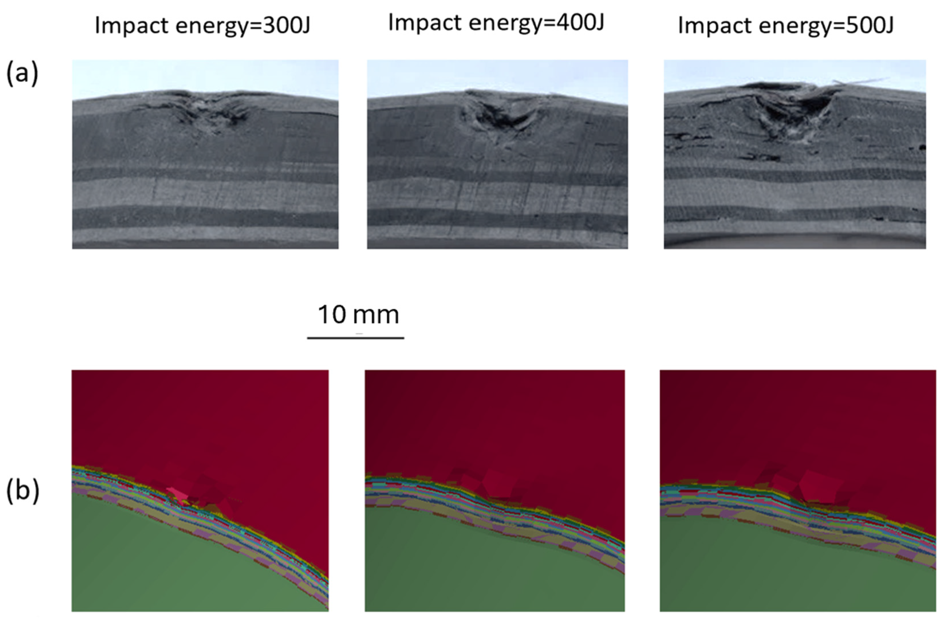
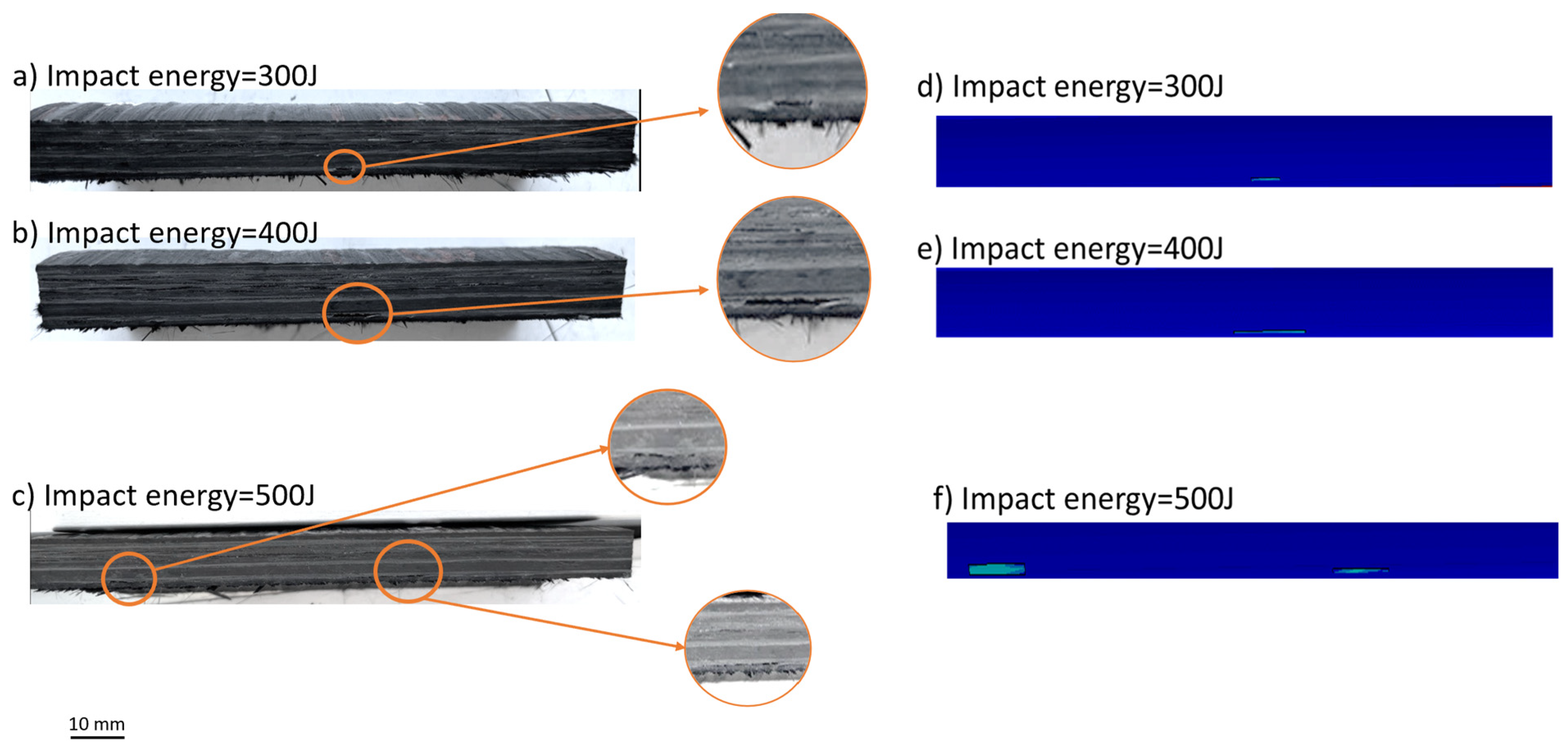
3.1. Comparing Numerical and Experimental Results

This section delves into validating the numerical models through extensive comparisons with experimental results obtained from impact tests. These tests were designed to evaluate how these vessels respond to varying levels of impact energy, utilizing two distinct types of impactors to simulate different real-world scenarios.
To illustrate the effectiveness of the numerical model, we refer to Figure 4, which provides a detailed visual representation of the outcomes from the numerical simulations. This figure highlights the extent and nature of matrix damage observed at the impact site on the composite cylinders following the impacts. Specifically, the analysis focused on tests with a 6 mm spherical impactor, carefully selected for its ability to replicate common impact conditions.
The data presented in both Figure 4 and Table 3 show that the numerical model can replicate the damage compared to the experimental results. The legend related to the numerical results shows the damage index related to the matrix damage in which the damage index equal to 1 or red colors represent the matrix damage in the structure. By comparing the numerical and experimental results, it is clear that while the model has a strong predictive capability, it may slightly overestimate the extent of damage incurred during impact events. In Table 3, the dimension of the damage in the axial direction has been considered as the length of the damage and the dimension of the damage in the hoop direction is the damage width.
Figure 5 illustrates the indentations observed in the composite cylinders following impact tests conducted with varying energy levels using the 6 mm spherical impactor. The figure clearly shows the resulting indentations in the experimental samples, indicating the structure’s response to the applied loads. The numerical results complement these findings by accurately predicting the indentation patterns across all tested scenarios.
Based on the experimental results, it is evident that the location and extent of delamination failures vary with different impact energies and impactors. However, in all samples, delamination occurred exclusively between layers with a fiber orientation of 90 degrees and other angles. For instance, in Figure 4a, delamination occurred at the interface between the layer with a 90-degree orientation and the layer with an 18-degree orientation in the outer layers. Similarly, in Figure 4b, delamination is visible at the interface between the 90-degree and 18-degree layers in the bottom layers, with no delamination observed between layers with other fiber orientations. This consistent delamination pattern is also evident in Figure 5, where only the interface between the 90-degree and 18-degree layers experienced failure.
Additionally, it is essential to highlight that during the experimental tests, no indentations were observed in the cylinders subjected to impacts from the 120 mm cylindrical impactor. This suggests a significant difference in the deformation characteristics depending on the geometry and energy of the impacting object, potentially indicating the limitations of impact resistance in the tested cylinders when faced with larger impactors.
The results presented in Figure 6 depict the numerical model’s findings concerning delamination in composite cylinders following impact loading with a 6 mm spherical impactor. The whole blue color indicates the cross section of the composite vessel and the light green lines represent the delamination lines according to the numerical model. The analysis indicates that delamination occurred exclusively at the interfaces between the layers oriented at 90 degrees and the adjacent layers. Delamination did not occur at the interfaces between layers with other orientations. This observation was consistent across both the numerical model and experimental results. Table 3 presents the dimensions pertaining to the length of the delamination occurring in the cross-section view.
Figure 7 illustrates the delamination results observed in composite cylinders subjected to impact from a 120 mm cylindrical impactor, tested under varying impact energies. The delamination failures depicted in the figure are visible at the cross-section after cutting the samples. The delamination consistently occurs at the bottom interface across all tested configurations. This bottom interface is characterized as the boundary between layers oriented at 90 degrees and those at 18 degrees. The data suggest that the orientation of the layers plays a critical role in the delamination behavior, with increased impact energy correlating with more significant delamination at this specific interface.
Based on both numerical and experimental results, it is evident that the location and extent of delamination failures vary with different impact energies and impactors. However, in all samples, delamination occurred exclusively between layers with a fiber orientation of 90 degrees and other angles. For instance, in Figure 6a, delamination occurred at the interface between the layer with a 90-degree orientation with an 18-degree orientation in the outer layers. Similarly, in Figure 6b,c, delamination is visible at the interface between the 90-degree and 18-degree layers in the bottom layers, with no delamination observed between layers with other fiber orientations. This consistent delamination pattern is also evident in Figure 7, where only the interface between the 90-degree and 18-degree layers experienced failure.
Table 3 provides a comprehensive overview of the dimensions associated with various types of damage—specifically, matrix damage, delamination, and indentation—observed in composite cylinders subjected to impact loading under three distinct energy levels and using two different impactors. The results indicate a clear trend: As the impact energy increases across all tested cases, the size of the resulting damage also tends to grow. This suggests a direct correlation between the impact’s energy and the structural damage’s severity.
Moreover, a noteworthy distinction arises when comparing the effects of the two impactors used in the experiments. When the 6 mm spherical impactor was employed, the composite structure experienced three types of failures: matrix damage, indentation, and delamination. Conversely, when the larger 120 mm cylindrical impactor was applied, the damage observed was exclusively delamination, despite maintaining the same impact energy levels. This shift highlights the significant influence that impactor geometry has on the failure modes experienced by composite materials in impact situations.
Additionally, in every instance examined, it is evident that the numerical model produces results that closely align with the experimental data. This consistency suggests that the model accurately captures the underlying damage phenomena being studied, thereby reinforcing its validity and reliability for future applications.

3.2. The Influence of Impactor Shape on the Impact Damage

In this section, we explore how the geometry of the impactor affects the damage caused by impacts. We leverage the validated numerical model presented in Section 3.1 to conduct this investigation. This model is a reliable foundation for analyzing various impactor shapes and their effects on structural integrity during impact events. By systematically varying the geometry of the impactor, we can observe and quantify the resultant damage patterns, providing a comprehensive understanding of the relationship between impactor shape and impact-induced damages.
In this section, we analyze the effects of six distinct geometries for impactor shapes in our impact analysis. The two primary geometric configurations considered are spherical and cylindrical shapes. Each shape is evaluated in three different diameters: 6 mm, 50 mm, and 120 mm. This results in a total of six combinations of impactor shapes and sizes.
For each type of impactor, we explore three varying levels of impact energy (300 J, 400 J, and 500 J), allowing us to assess how different shapes and dimensions interact under various energetic conditions. This comprehensive approach aims to deepen our understanding of the impact dynamics associated with each geometry.
Figure 8 illustrates the areas of delamination observed on the composite cylinders following impact loading across various impact energies and with different types of impactors. The data presented in the figure indicate a clear trend: As the impact energy is increased, the extent of delamination also expands in all examined scenarios. Notably, using a spherical impactor results in a larger delamination area compared to using a cylindrical impactor. Furthermore, as shown in Figure 8, in all impact energies, the rate at which delamination increases when using cylindrical impactors is significantly less pronounced than that observed with spherical impactors, suggesting that the geometry of the impactor plays a critical role in determining the extent of damage to the composite cylinders. This indicates a complex relationship between impactor shape, energy levels, and the resulting structural integrity of the composite cylinders.
Figure 9 illustrates the matrix damage observed in composite cylinders following impact loading. The data presented demonstrate a clear correlation between impact energy and the resulting area of matrix damage: As impact energy increases, the extent of damage also grows across all types of impacts. Furthermore, at a constant energy level, an increase in the diameter of the impactor corresponds to a larger matrix damage area.
These findings underscore the importance of the impactor’s dimensions and shape, as they play a crucial role in determining the extent of damage inflicted on composite structures. The significant variation in damage behavior based on these factors highlights the complexity of material responses to different impact scenarios.
Conversely, in instances where spherical impactors are used, a different pattern of damage emergence is observed. When a 6 mm spherical impactor is employed, the resulting matrix damage tends to be predominantly localized around the central impact area, akin to the impact pattern observed with spherical impactors. However, as the diameter of the cylindrical impactors increases, a shift occurs: The damage area begins to extend toward the periphery of the impact point rather than remaining centralized. This change can be attributed to the geometry of the larger impactor; with a broader diameter, the edges of the impactor exert more influence, causing damage to the sides of the impact point more significantly than to the center. This tendency to spread damage outward is not evident in impacts made with spherical impactors, which consistently maintain a focused damage area.
Figure 10 illustrates the phenomenon of fiber breakage within composite cylinders subjected to low-velocity impacts by various impactors at different impact energy levels. The data presented in the figure indicate a clear correlation between the increase in impact energy and the expansion of the damage area; as the impact energy rises, so does the extent of the damage. Furthermore, a notable trend emerges whereby the diameter of the impactors also plays a significant role in determining the size of the damage zone. The spherical and cylindrical impactors demonstrate a similar pattern regarding the damage area inflicted during their respective impacts. Specifically, in cases where composite cylinders are impacted with spherical impactors, altering the diameter of the impactor results in a consistent shape of the damage area. However, the overall size of the damage area increases proportionately with the diameter of the impactor.
Notably, when examining impacts made with spherical impactors, the smallest diameter impactor (6 mm) predominantly caused damage along the axial rather than the hoop direction. However, as the diameter of the spherical impactors increased, the matrix damage area expanded more significantly in the hoop direction. This shift in damage patterns is characterized by the dimensions of the damaged area becoming roughly equivalent in length and width.
A similar trend is observed in composite cylinders subjected to cylindrical impactors. With the smaller impactors of 6 mm and 50 mm diameters, damage propagation occurred almost equally in axial and hoop directions. In contrast, when a larger cylindrical impactor with a diameter of 120 mm was used, the matrix damage area escalated primarily in the axial direction.
In conclusion, the data highlight that while both impactor shapes exhibit increases in damage area with rising impact energy, their distinct geometric properties lead to different behaviors in damage distribution, particularly regarding the role that the edge of the impactor plays in the damage inflicted on composite materials.
The observations in Table 4 indicate that as the impact energy and the diameter of the impactor increase, there is a corresponding growth in the damage area across all types of damage observed. This trend suggests a direct relationship between the intensity of the impact and the extent of the resulting damage. However, an intriguing aspect arises from these data: The damage area’s morphology and the damage’s localization can vary significantly when different impactors are employed during the impact loading process. This variability in damage patterns highlights the importance of impactor characteristics in determining the nature and severity of damage, suggesting that not all impacts are created equal, even under similar energy conditions.

4. Conclusions

The study offers new insights into the relationship between impactor geometry and composite configuration, which directly influences the damage processes of composites, such as delamination and matrix failure. The research emphasizes the significant role of impactor shape in determining the extent of damage, providing practical implications for design optimization and safety protocols in composite pressure vessels.
We agree that future studies are essential to further investigate the complex interactions between various impactor geometries and composite material configurations. This will deepen our understanding of damage propagation and improve the resilience of composite structures under impact loading.
In this study, we have conducted a comprehensive investigation into the damage mechanisms associated with low-velocity impacts on filament wound carbon fiber composite pressure vessels, specifically emphasizing the influence of impactor geometry. The experimental and numerical analyses have yielded critical insights into the relationship between the shape and size of the impactors and the resulting damage patterns observed in composite materials.
The findings suggest that the geometry of the impactor is a significant factor in determining both the nature and extent of the damage inflicted on the composite vessels. Notably, employing a 6 mm spherical impactor combined matrix damage, indentation, and delamination. Conversely, applying a larger 120 mm cylindrical impactor predominantly induced delamination, irrespective of the impact energy expended. This alteration in damage modes highlights the necessity of considering impactor characteristics when assessing the structural integrity of composite materials.
Additionally, the results reveal a distinct correlation between impact energy and the severity of damage, whereby increased energy levels correspond to larger damage areas across various failure types. The consistent occurrence of delamination exclusively at the interfaces between layers exhibiting a 90-degree fiber orientation and adjacent layers further emphasizes the crucial role of fiber orientation in the damage behavior of composite structures.
The validated numerical model developed in this research has demonstrated reliability in predicting damage mechanisms and aligns closely with experimental outcomes. This model enhances our understanding of impact dynamics and serves as a valuable resource for future studies aimed at optimizing the design and application of composite materials in contexts such as high-pressure hydrogen storage and other engineering applications.
In conclusion, this research significantly contributes to the existing body of knowledge regarding the impact behavior of composite pressure vessels. The insights obtained from this study are essential for enhancing safety protocols and design strategies, thereby ensuring the reliability and performance of composite materials in practical applications. Future research efforts should continue to investigate the interactions between different impactor geometries and composite configurations to refine our understanding of damage mechanisms further and improve these critical structures’ resilience.
For future research, we will specifically address the exploration of additional impactor geometries (e.g., sharp-edged, oblique, or irregular shapes) to further understand the role of impact geometry in damage mechanisms. Additionally, testing under operational conditions, such as those involving cyclic loading or extreme environmental factors, could provide further insights into the long-term durability of composite vessels and refine the design parameters for safer, more resilient pressure vessels.

Author Contributions

Conceptualization, S.R.A., A.M., C.S. and D.M.; methodology, S.R.A. and D.M.; software, S.R.A.; validation, S.R.A.; formal analysis, S.R.A.; investigation, S.R.A.; resources, S.R.A.; data curation, S.R.A. and D.M.; writing—original draft preparation, S.R.A.; writing—review and editing, D.M., A.M. and C.S.; visualization, S.R.A., D.M., A.M. and C.S.; supervision, A.M. and C.S.; project administration, A.M. and C.S.; funding acquisition, A.M. All authors have read and agreed to the published version of the manuscript.

Funding

This research received no external funding.

Data Availability Statement

Data will be available upon request.

Acknowledgments

Authors acknowledge FABER Cylinders for the supply of the filament wound composite cylinders.

Conflicts of Interest

The authors declare no conflicts of interest.

References

  1. Zheng, J.; Liu, X.; Xu, P.; Liu, P.; Zhao, Y.; Yang, J. Development of high pressure gaseous hydrogen storage technologies. Int. J. Hydrogen Energy 2012, 37, 1048–1057. [Google Scholar] [CrossRef]
  2. Azeem, M.; Ya, H.H.; Alam, M.A.; Kumar, M.; Stabla, P.; Smolnicki, M.; Gemi, L.; Khan, R.; Ahmed, T.; Ma, Q.; et al. Application of filament winding technology in composite pressure vessels and challenges: A review. J. Energy Storage 2022, 49, 103468. [Google Scholar] [CrossRef]
  3. Rivard, E.; Trudeau, M.; Zaghib, K. Hydrogen storage for mobility: A review. Materials 2019, 12, 1973. [Google Scholar] [CrossRef]
  4. Xu, P.; Zheng, J.; Chen, H.; Liu, P. Optimal design of high pressure hydrogen storage vessel using an adaptive genetic algorithm. Int. J. Hydrogen Energy 2010, 35, 2840–2846. [Google Scholar] [CrossRef]
  5. Choi, I.H. Low-velocity impact response analysis of composite pressure vessel considering stiffness change due to cylinder stress. Compos. Struct. 2017, 160, 491–502. [Google Scholar] [CrossRef]
  6. Liao, B.; Jia, L.; Zhou, J.; Lei, H.; Gao, R.; Lin, Y.; Fang, D. An explicit–implicit combined model for predicting residual strength of composite cylinders subjected to low velocity impact. Compos. Struct. 2020, 247, 112450. [Google Scholar] [CrossRef]
  7. Gemi, D.S.; Şahin, Ö.S.; Gemi, L. Experimental investigation of the effect of diameter upon low velocity impact response of glass fiber reinforced composite pipes. Compos. Struct. 2021, 275, 114428. [Google Scholar] [CrossRef]
  8. Kim, S.-W.; Kim, E.-H.; Jeong, M.-S.; Lee, I. Damage evaluation and strain monitoring for composite cylinders using tin-coated FBG sensors under low-velocity impacts. Compos. Part B Eng. 2015, 74, 13–22. [Google Scholar] [CrossRef]
  9. Maziz, A.; Tarfaoui, M.; Gemi, L.; Rechak, S.; Nachtane, M. A progressive damage model for pressurized filament-wound hybrid composite pipe under low-velocity impact. Compos. Struct. 2021, 276, 114520. [Google Scholar] [CrossRef]
  10. Liao, B.; Jia, L. Finite element analysis of dynamic responses of composite pressure vessels under low velocity impact by using a three-dimensional laminated media model. Thin-Walled Struct. 2018, 129, 488–501. [Google Scholar] [CrossRef]
  11. Han, M.-G.; Chang, S.-H. Failure analysis of a Type III hydrogen pressure vessel under impact loading induced by free fall. Compos. Struct. 2015, 127, 288–297. [Google Scholar] [CrossRef]
  12. Weerts Ruben, A.J.; Cousigné, O.; Kunze, K.; Geers, M.G.D. A methodological approach to model composite overwrapped pressure vessels under impact condi-tions. Compos. Struct. 2021, 276, 114482. [Google Scholar] [CrossRef]
  13. Perillo, G.; Grytten, F.; Sørbø, S.; Delhaye, V. Numerical/experimental impact events on filament wound composite pressure vessel. Compos. Part B Eng. 2015, 69, 406–417. [Google Scholar] [CrossRef]
  14. Gemi, L.; Kayrıcı, M.; Uludağ, M.; Gemi, D.S.; Şahin, Ö.S. Experimental and statistical analysis of low velocity impact response of filament wound composite pipes. Compos. Part B Eng. 2018, 149, 38–48. [Google Scholar] [CrossRef]
  15. Zhao, X.; Liang, J.; Zhao, C.; Liu, J.; Li, Y.; Jiang, L.; Feng, J.; Xue, Y. Experimental and numerical analysis of low-velocity impact behavior of wound products using multi-filament winding technique. J. Mater. Res. Technol. 2023, 25, 7292–7306. [Google Scholar] [CrossRef]
  16. Farhood, N.H. Low velocity impact simulation of cylindrical section for type IV composite pressure vessels. AIP Conf. Proc. 2021, 2372, 150001. [Google Scholar]
  17. Allen, T.; Ahmed, S.; Hepples, W.; Reed, P.A.; Sinclair, I.; Spearing, M. A comparison of quasi-static indentation and low-velocity impact on composite overwrapped pressure vessels. J. Compos. Mater. 2018, 52, 4051–4060. [Google Scholar] [CrossRef]
  18. Farhood, N.H.; Karuppanan, S.; Ya, H.H.; Ovinis, M. Experimental study of low velocity impact response of carbon/basalt hybrid filament wound composite pipes. Int. J. Struct. Stab. Dyn. 2018, 18, 1850089. [Google Scholar] [CrossRef]
  19. Farhood, N.H.; Karuppanan, S.; Ya, H.H.; Sultan, M. Experimental investigation on the effects of glass fiber hybridization on the low-velocity impact response of filament-wound carbon-based composite pipes. Polym. Polym. Compos. 2021, 29, 829–841. [Google Scholar] [CrossRef]
  20. Trevor Matthew, A. Damage Development and Post-Impact Performance of Composite Overwrapped Pressure Vessels Subjected to Low Velocity Impact. Ph.D. Thesis, University of Southampton, Southampton, UK, 2017. [Google Scholar]
  21. Wu, Q.; Chen, X.; Fan, Z.; Jiang, Y.; Nie, D. Experimental and numerical studies of impact on filament-wound composite cylinder. Acta Mech. Solida Sin. 2017, 30, 540–549. [Google Scholar] [CrossRef]
  22. Long, B.; Yang, N.; Cao, X. Low-velocity impact damages of filament-wound composite overwrapped pressure vessel (COPV). J. Eng. Fibers Fabr. 2022, 17, 15589250221088895. [Google Scholar] [CrossRef]
  23. Available online: https://lsdyna.ansys.com/manuals/ (accessed on 1 May 2025).
  24. Rezaei Akbarieh, S.; Ma, D.; Sbarufatti, C.; Manes, A. Numerical Investigation on the Capability of Modeling Approaches for Composite Cylinders under Low-Velocity Impact Loading. J. Compos. Sci. 2024, 8, 141. [Google Scholar] [CrossRef]
  25. Akbarieh, S.R.; Ma, D.; Sbarufatti, C.; Manes, A. Numerical model of curved composite tiles under low-velocity impact loading. J. Compos. Mater. 2024, 59, 661–680. [Google Scholar] [CrossRef]
Figure 1. Carbon fiber filament winding composite pressure vessel manufacturing.
Modelling 06 00041 g001
Figure 2. Impact test setup: (a) impact machine with the spherical impactor with 6 mm diameter; (b) impact machine with the cylindrical impactor with 120 mm diameter.
Modelling 06 00041 g002
Figure 3. Numerical model made for the impact loading on the composite vessel: (a) with the 6 mm spherical impactor; (b) with the solid cylindrical impactor based on the experimental setup.
Modelling 06 00041 g003
Figure 4. Matrix damage related to the impact applied by 6 mm spherical impactor: (a) numerical results; (b) experimental results.
Modelling 06 00041 g004
Figure 5. The indentation happened in the cylinders after being impacted with 6 mm spherical impactor in different energies: (a) experimental results; (b) numerical results.
Modelling 06 00041 g005
Figure 6. The delamination results after the impact loading with a 6 mm spherical impactor: (a) numerical results; (b) experimental results.
Modelling 06 00041 g006
Figure 7. The delamination results after the impact loading with 120 mm cylindrical impactor: (ac) experimental results for the delamination; (df) numerical results for the delamination.
Modelling 06 00041 g007
Figure 8. Delamination results for the composite cylinders impacted with different impactors under three different impact energies of (a) 300 J, (b) 400 J, and (c) 500 J.
Modelling 06 00041 g008
Figure 9. Matrix damage with different impactors with (a) 300 J, (b) 400 J, and (c) 500 J impact energy.
Modelling 06 00041 g009
Figure 10. Fiber breakage failure with different impactors in three different impact energies of (a) 300 J, (b) 400 J, and (c) 500 J.
Modelling 06 00041 g010
Table 1. Material properties of the composite T700s [25].
PropertyValue
Density1.8 g c m 3
Longitudinal Tensile Strength2450 M P a
Longitudinal Compressive Strength1570 M P a
Longitudinal Young Modulus125 G P a
Transverse/Normal Young Modulus7800 M P a
Transverse Compressive Strength150 M P a
Transverse Tensile Strength70 M P a
Shear Strength98 M P a
Shear Failure Stress 60   M P a
Normal Failure Stress 70   M P a
Table 2. Stacking sequence for the pressure vessels.
Layer NumberAngle (°)Minimum Thickness (mm)
1900.90
2180.75
3902.00
4200.80
5700.80
6400.80
7270.80
8320.80
9180.80
10900.85
Table 3. The low-velocity impact damage results on the composite cylinders with different impactors and different impact energies.
Impactor
Shape/Size
ResultsSurface Damage DelaminationIndentation
Impact Energy (J)Impact Energy (J)
300 400 500300400500
Impact Energy (J)
Length (mm)Width (mm)Length (mm)Width (mm)Length (mm)Width (mm)Length (mm)Length
(mm)
Length
(mm)
300400500
6 mm SphericalExperimental63941167.64.2322.33.54.8
Numerical751061368.25343.14.75.5
120 mm CylindricalExperimental-2.686–6.6-
Numerical3.29.57–8.5
Table 4. The damage area happened after the impact loading with different impactors in various impact energies.
Impactor
Diameter (mm)
Impact
Energy (J)
Matrix
Damage Area (mm2)
Delamination
Area (mm2)
Fiber Breakage Area (mm2)
Spherical Impactor63002880405040
4003520515247
5005655589052
5030038887830110
400478410,664168
500720811,189230
12030043685712132
400494010,836192
500660012,062247
Cylindrical Impactor6300190898830
40051922112156
50051667616182
503005032528169
400570010,010210
500748014288288
1203008580126060
4009088272076
5009920844880
Disclaimer/Publisher’s Note: The statements, opinions and data contained in all publications are solely those of the individual author(s) and contributor(s) and not of MDPI and/or the editor(s). MDPI and/or the editor(s) disclaim responsibility for any injury to people or property resulting from any ideas, methods, instructions or products referred to in the content.

