Article

Effect of Vacancy Defect on Mechanical Properties of Single Wall Carbon Nanotube

1
Joint School of Nanoscience and Nanoengineering, North Carolina A&T State University, Greensboro, NC 27411, USA
2
Department of Mechanical Engineering, North Caolina A&T State University, Greensboro, NC 27411, USA
*
Author to whom correspondence should be addressed.
Appl. Nano 2025, 6(3), 12; https://doi.org/10.3390/applnano6030012
Submission received: 28 February 2025 / Revised: 23 June 2025 / Accepted: 25 June 2025 / Published: 27 June 2025
(This article belongs to the Collection Feature Papers for Applied Nano)

Abstract

Carbon nanotubes (CNTs) are cylindrical nanostructures formed by rolling a graphene sheet—a hexagonal lattice of carbon atoms—into a tube. Based on the rolling direction, CNTs are categorized as armchair, zigzag, or chiral. The chiral vector, derived from the graphene lattice, defines the CNT’s structure, with chiral CNTs denoted by indices (n, m), where m > 0 and m ≠ n. The mechanical properties and structural stability of CNTs are highly sensitive to defects and impurities within their atomic framework. Among these, point defects such as single-atom vacancies are the most prevalent and can significantly degrade mechanical performance. These defects alter stress distribution, reduce stiffness, and impair strength, thereby limiting the functional reliability of CNTs in advanced applications such as nanocomposites, sensors, and electronic devices. This study examines the influence of vacancy defects on CNT mechanical behavior through a multiscale modeling framework. Molecular dynamics (MD) simulations are conducted using LAMMPS, with structural visualization via Visual Molecular Dynamics (VMD). Concurrently, a finite element (FE) model is developed in ANSYS, where the CNT is idealized as a space frame of elastic beam elements representing carbon–carbon bonds. The integration of atomistic and continuum approaches offers a comprehensive understanding of defect-induced mechanical degradation. The MD and FEM results are in strong agreement with findings in existing literature, validating the adopted methodology. These findings contribute valuable insights into the design and optimization of CNT-based materials for high-performance engineering applications.
Keywords:
CNT; defects; LAMMPS; VMD; ANSYS; MD; FEM

1. Introduction

Carbon nanotubes (CNTs) were first discovered in 1991 by Japanese physicist Sumio Iijima, who observed needle-like tubular structures on the cathode of an arc discharge experiment [1]. This seminal discovery sparked extensive research into CNTs, catalyzing major developments in nanotechnology, materials science, and nanoelectronics.
Structurally, CNTs are cylindrical nanostructures formed by rolling graphene sheets—an allotrope of carbon—into seamless tubes [2]. Based on their morphology, CNTs are broadly categorized into two types:
  • Single-walled carbon nanotubes (SWCNTs) comprising a single graphene sheet rolled into a cylinder;
  • Multi-walled carbon nanotubes (MWCNTs) composed of multiple concentric graphene cylinders nested within one another.
The unique physical, electrical, and optical properties of SWCNTs are governed by their chirality, which describes the specific rolling vector of the graphene sheet. This structural parameter determines whether a CNT behaves as a metallic or semiconducting material, making chirality a key factor in their functional applications.
As illustrated in Figure 1, the rolling direction of the graphene sheet directly determines the resulting structural configuration of the carbon nanotube. When the sheet is rolled along the armchair direction, an armchair single-walled carbon nanotube (SWCNT) is formed. Conversely, rolling along the zigzag direction yields a zigzag SWCNT. Any other rolling direction results in a chiral SWCNT, characterized by a chiral vector Ch originating from the lattice point (0,0). This chiral vector can be mathematically expressed in terms of the graphene lattice unit vectors â1 and â2, as shown in Equation (1) [3]:
Ch = nâ1 + mâ2,
In this equation, if m = 0, the nanotube is classified as a zigzag nanotube, and if m = n, it is an armchair nanotube.

1.1. Molecular Dynamics Simulation for CNT

Molecular dynamics (MD) simulations have emerged as a powerful and cost-effective tool for predicting the properties of materials at the atomic scale, including carbon nanotubes (CNTs). By enabling detailed analysis of interatomic interactions, MD simulations serve as a valuable alternative to experimental approaches, particularly in the investigation of nanoscale phenomena. This study employs MD simulations to examine the mechanical properties of single-walled carbon nanotubes (SWCNTs), both in pristine form and in the presence of structural defects.
CNTs possess a unique hexagonal graphite-like atomic structure that imparts exceptional mechanical strength, notably a high Young’s modulus [4]. However, this strength is highly sensitive to structural imperfections. Numerous experimental and computational studies have reported a wide range of values for the Young’s modulus of SWCNTs. For instance, Kelkar et al. estimated a Young’s modulus of 0.92 TPa for defect-free SWCNTs using MD simulations [4], while Bedi et al. reported a higher value of 1.72 Tpa [5]. The introduction of point defects, such as single-atom vacancies, has been shown to significantly reduce stiffness, with values dropping to approximately 0.69 Tpa [6].

1.2. Effect of Defects on the Properties of CNT

Defects in carbon nanotubes (CNTs), particularly point defects, play a critical role in modifying their mechanical and electrical properties. Among the various defect types, point defects—such as vacancies and atomic dislocations—are the most frequently observed imperfections in single-walled carbon nanotubes (SWCNTs). These defects significantly influence electrical conductivity, mechanical strength, and overall structural stability [7]. Typically, such imperfections emerge post-synthesis due to environmental exposure, mechanical stress, or limitations inherent in the fabrication process [8].
To investigate the effects of point defects on CNT behavior, this study employs the Large-Scale Atomic/Molecular Massively Parallel Simulator (LAMMPS) [9] for molecular dynamics simulations and Visual Molecular Dynamics (VMD) [10] for structural visualization. These tools are widely recognized for their robustness, scalability, and reliability in simulating nanoscale systems.
The simulation results obtained are consistent with those in the existing literature, validating the methodology and highlighting the substantial impact of point defects on the mechanical response of CNTs. These findings offer critical insights into defect-induced material degradation and contribute to the informed design of CNT-based components in nanotechnology, electronics, and advanced structural applications.

2. Modeling and Simulation

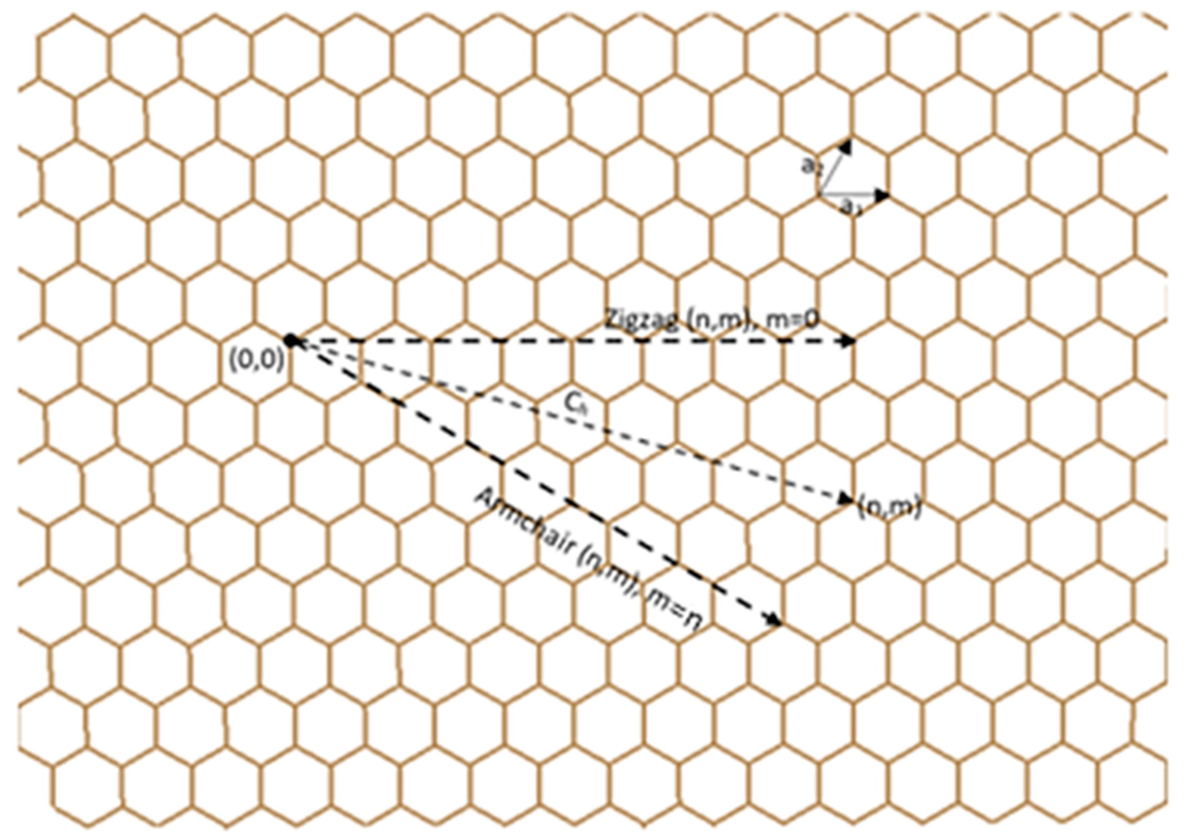
2.1. Modeling Procedure

The structural modeling of single-walled carbon nanotubes (SWCNTs) in this study follows the standard (n, m) nomenclature, which defines both the chirality and geometry of the nanotube, as described in [11]. Three armchair configurations, (5,5), (10,10), and (15,15), and three zigzag configurations, (5,0), (10,0), and (15,0), were constructed using the Nanotube Builder plugin in Visual Molecular Dynamics (VMD). Each nanotube was modeled with a uniform length of 100 Å to maintain a consistent aspect ratio across all configurations for comparative analysis.
Following the structural generation, the Cartesian coordinates of all atoms were extracted from VMD and converted into a format compatible with the Large-Scale Atomic/Molecular Massively Parallel Simulator (LAMMPS) for molecular dynamics (MD) simulations. This facilitated a seamless workflow from structural modeling to computational analysis, preserving atomic accuracy.
The mechanical response of the CNTs was investigated using LAMMPS, a widely used and efficient platform for atomistic simulations. The Adaptive Intermolecular Reactive Empirical Bond Order (AIREBO) potential [12] was employed to describe carbon–carbon (C–C) interactions. A cut-off distance of 3.4 Å was specified, allowing the potential to capture key phenomena such as bond stretching, bond breaking, and van der Waals forces—essential for accurately predicting the mechanical behavior of CNTs.
To replicate a physically realistic environment, non-periodic and shrink-wrapped boundary conditions were applied. These conditions effectively eliminated artificial interactions at the simulation box boundaries, preventing unphysical atomic displacements and ensuring the integrity of the CNT structure during deformation.

2.2. Simulation Procedure

The simulation process involved multiple key steps to ensure numerical accuracy and stability:

2.2.1. Energy Minimization

Prior to mechanical testing, the initial atomic configurations were subjected to energy minimization using the conjugate gradient method. This process was essential for eliminating residual stresses and unphysical atomic overlaps, thereby yielding a relaxed and energetically stable CNT structure.

2.2.2. Equilibration Using NVT Ensemble

Following energy minimization, the system was equilibrated at 300 K using the canonical (NVT) ensemble, which maintains a constant number of particles (N), volume (V), and temperature (T). The equations of motion were integrated using the Velocity—Verlet algorithm with a time step of 1 femtosecond (fs), ensuring accurate resolution of atomic trajectories throughout the simulation.

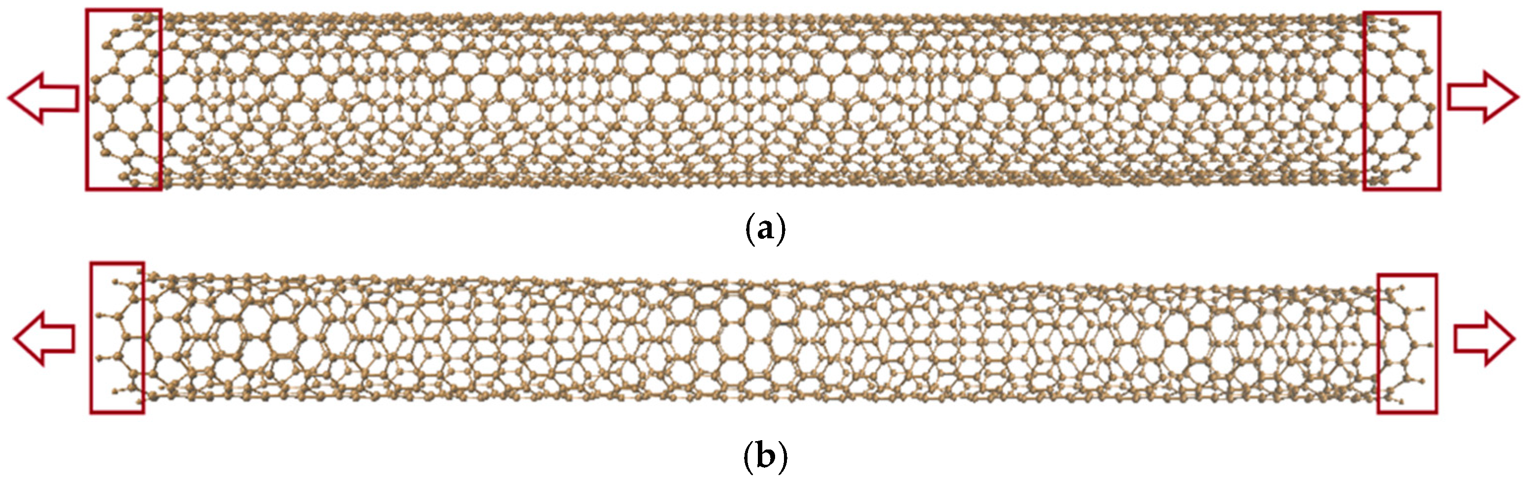
2.2.3. Application of Tensile Load

Following equilibration, a uniaxial tensile load was applied along the longitudinal axis of each nanotube until structural failure occurred. The resulting stress–strain response was recorded to evaluate key mechanical properties, including Young’s modulus, ultimate tensile strength (UTS), and fracture behavior.
Figure 2a illustrates the armchair configuration, while Figure 2b depicts the zigzag configuration of the SWCNTs subjected to uniaxial tensile loading. Tensile deformation is simulated by fixing both ends of the nanotube and applying an outward displacement until structural failure occurs.

2.3. Defects in Carbon Nanotubes (CNT)

In practical applications, carbon nanotubes (CNTs) frequently exhibit structural defects that can markedly affect their mechanical, electrical, and thermal performance. Among the various types of defects, point defects—commonly referred to as vacancies—are the most prevalent [8]. These defects arise from the absence of one or more carbon atoms, leading to local disruptions in the atomic lattice, which in turn alter stress distribution and can diminish mechanical strength as well as modify electronic behavior.
To replicate such real-world imperfections, vacancy defects were intentionally introduced at random locations within the SWCNT models. A comparative analysis was then performed between pristine (defect-free) SWCNTs and their defect-containing counterparts. The mechanical implications of these vacancies were evaluated by examining variations in Young’s modulus, fracture strength, and strain distribution under applied loading. Figure 3 presents a representative SWCNT structure with vacancy defects, clearly illustrating the missing atoms that interrupt the otherwise continuous hexagonal carbon network.
By systematically introducing and analyzing point defects, this study offers critical insights into the influence of atomic-scale imperfections on the structural integrity of carbon nanotubes. The results advance the understanding of defect-induced mechanical degradation, which is essential for the design and optimization of CNT-based materials in advanced engineering and nanotechnology applications.

3. Results and Discussion

The following Table 1 shows the ultimate stress and strain in the tube that is under tension:
The mechanical properties of armchair and zigzag single-walled carbon nanotubes (SWCNTs) with varying chirality and diameter were investigated using molecular dynamics simulations. Figure 4 and Figure 5 present the stress–strain responses of nanotubes with (5,5), (10,10), and (15,15) armchair configurations and (5,0), (10,0), and (15,0) zigzag configurations. These plots reveal critical insights into the elastic response, yield behavior, and failure mechanisms of CNTs as a function of their structural parameters, offering a comparative understanding of how chirality and diameter influence mechanical performance.

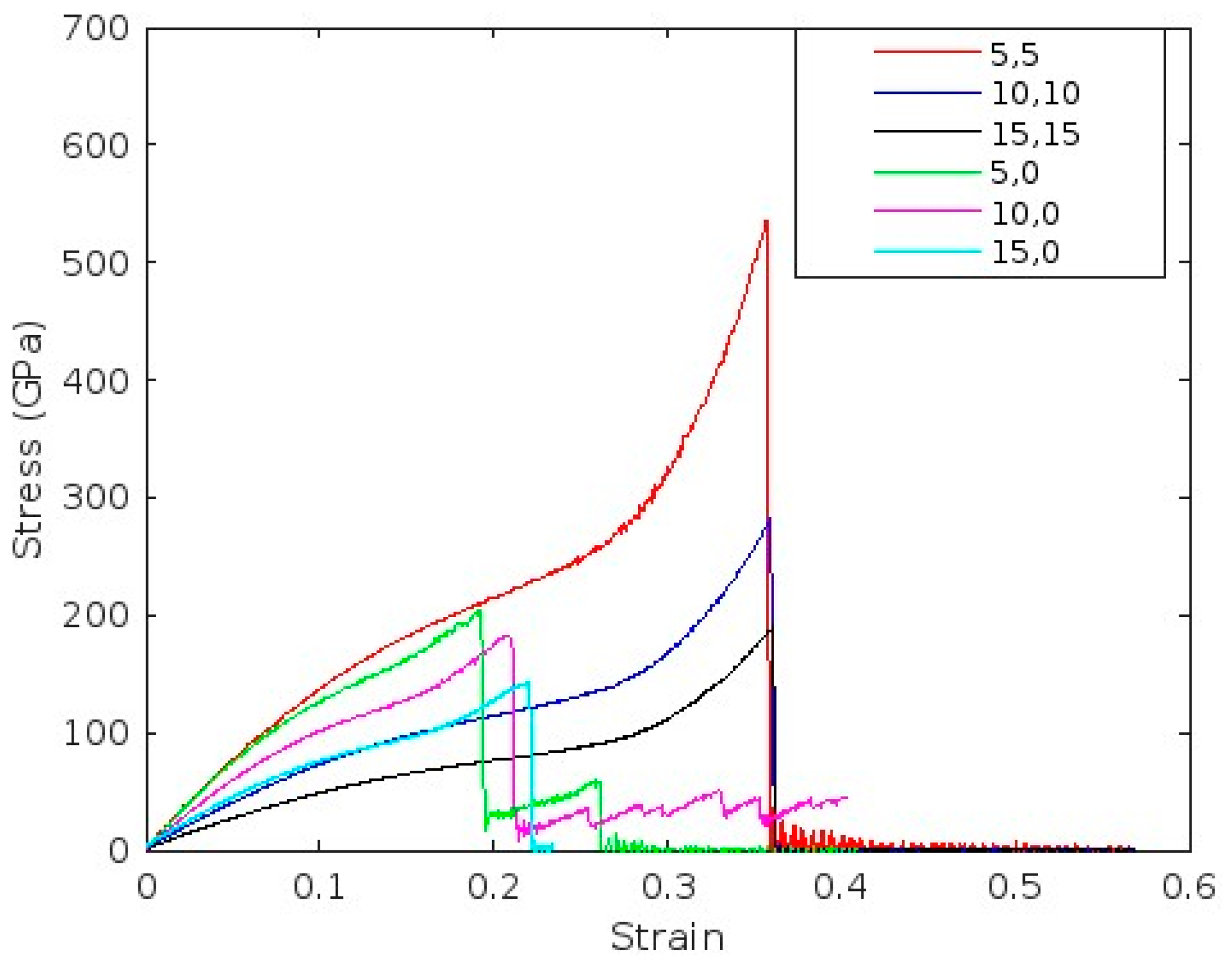
3.1. Stress–Strain Relationship and Young’s Modulus Calculation

To assess the mechanical strength of the nanotubes, Young’s modulus was calculated from the linear elastic region of the stress–strain curve. This region is characterized by a proportional increase in stress with strain, indicating purely elastic deformation of the nanotube. Elastic behavior persists up to the yield point, beyond which strain begins to increase more rapidly than stress, signaling the transition to plastic deformation.
Following the yield point, further elongation of the nanotube requires increased applied stress, as resistance to deformation intensifies. This continues until the stress reaches its maximum value, known as the ultimate tensile strength. At this point, the nanotube undergoes structural failure, typically accompanied by a sharp drop in stress.
To ensure consistency across all simulations, a uniform strain rate of 0.0014 fs−1 was applied. Figure 4 and Figure 5 present the resulting stress–strain curves for both pristine and vacancy-defective CNTs, illustrating the differences in mechanical response due to defect presence.

3.2. Effect of Defects on Mechanical Strength

The introduction of vacancy defects leads to a noticeable reduction in peak stress values, indicating a decline in the overall mechanical strength of the carbon nanotubes. This degradation is primarily attributed to the disruption of the continuous hexagonal carbon lattice, which impairs the nanotube’s ability to efficiently carry mechanical loads.
At present, the literature offers limited insight into how vacancy defects affect the mechanical behavior across different chiralities of carbon nanotubes (CNTs), revealing a significant gap that this study seeks to address. From Figure 5, an interesting and seemingly counterintuitive observation is that the ultimate strength of the defective (5,5) nanotube remains higher than that of the defective (15,15) nanotube. This behavior can be explained by the influence of stress concentration effects. Due to its smaller diameter, the (5,5) CNT exhibits intensified local stress around the vacancy site, resulting in localized deformation rather than the propagation of a crack.
Additionally, the decline in ultimate strength is also attributed to variations in atomic configuration, bond orientation, and nanotube curvature. CNTs with lower chiral indices—such as the (5,5) armchair configuration—exhibit greater curvature and enhanced bond alignment along the loading axis. This structural arrangement facilitates more effective axial load transfer and results in higher stiffness and tensile strength. Conversely, as the chiral index increases, the nanotube diameter enlarges and curvature decreases, leading to bond orientations that are increasingly misaligned with the loading direction. This misalignment reduces the efficiency of stress transfer, thereby diminishing the effective stiffness and overall mechanical strength of the nanotube.
In contrast, the larger diameter of the (15,15) CNT allows for a broader stress distribution, which facilitates crack propagation and leads to premature failure. Consequently, despite the presence of identical defect types, the (5,5) nanotube demonstrates higher ultimate strength than the (15,15) counterpart.
Alternatively, zig-zag CNTs exhibit opposite behavior, demonstrating an increase in ultimate strength with increasing chirality. In low-chirality zigzag CNTs (e.g., (5,0)), the majority of carbon–carbon bonds are oriented nearly perpendicular to the nanotube axis. This configuration results in inefficient axial load transfer and induces significant pre-strain due to high curvature. Consequently, these structures exhibit lower ultimate tensile strength (UTS), particularly when vacancy defects are present.
As chirality increases (e.g., (15,0)), the nanotube diameter becomes larger, and the bond orientation gradually aligns more closely with the axial loading direction. This improved alignment enhances axial stiffness and reduces curvature-induced instability, contributing to better mechanical performance under tensile loading—even in the presence of defects.
Moreover, larger-diameter zigzag CNTs demonstrate improved defect tolerance. The increased circumference allows for more atoms to participate in load redistribution, thereby mitigating localized stress concentration around vacancies and delaying the onset of failure.

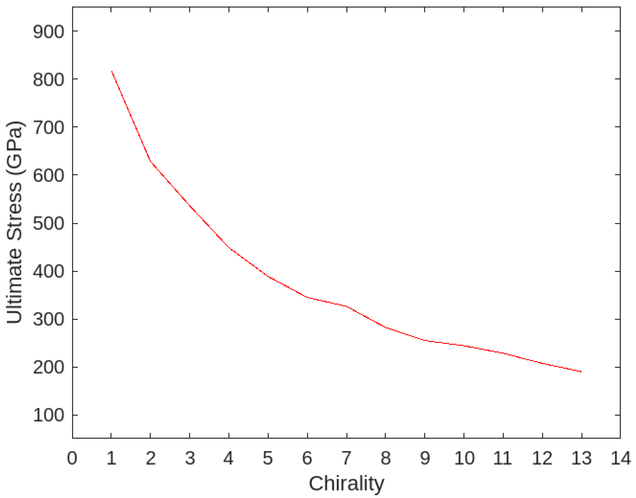
3.3. Effect of Chirality on the Ultimate Strength of Non-Defective CNT

The existing literature offers limited insight into the influence of chirality on the ultimate stress of armchair carbon nanotubes (CNTs), highlighting a gap that this study seeks to address. The mechanical behavior observed in this work demonstrates a consistent trend: ultimate stress decreases with increasing chirality. As shown in Figure 6, this decline in ultimate stress underscores the significant role of chirality in determining the mechanical performance of CNTs.
The (3,3) carbon nanotube exhibited an ultimate tensile strength of 818.36 GPa, whereas the (15,15) configuration demonstrated a significantly lower strength of 190.54 GPa. This pronounced decrease in ultimate stress with increasing chirality is primarily attributed to the corresponding increase in tube diameter, which leads to a reduction in axial stiffness. Molecular dynamics simulations reveal that CNTs with lower chirality possess a higher curvature, which enhances their resistance to axial deformation and promotes more efficient load transfer along the tube axis.

3.4. Effect of Vacancy Density on Young’s Modulus

The Young’s modulus of carbon nanotubes (CNTs) exhibits a pronounced decrease with increasing vacancy defect density. This degradation in stiffness is primarily attributed to the disruption of the continuous sp2-hybridized carbon bonding network, which compromises the structural integrity and load-bearing capacity of the nanotube.
As shown in Figure 7, the relationship between Young’s modulus and defect concentration underscores the significant sensitivity of CNT mechanical properties to atomic-scale imperfections.

3.5. Comparison of Young’s Modulus for Defective and Non-Defective CNTs

The calculated values of Young’s modulus for both pristine and defective single-walled carbon nanotubes (SWCNTs) are presented in Table 2. The results for non-defective CNTs show strong agreement with values reported in previous studies [5,13,14,15,16,17,18], thereby validating the simulation methodology employed in this work. Minor discrepancies among the reported values can be attributed to differences in modeling strategies, simulation parameters, and the choice of interatomic potentials across various studies.
In contrast, a significant reduction in Young’s modulus is observed for CNTs containing vacancy defects. This decline is primarily due to the disruption of atomic continuity and load transfer pathways caused by the vacancies, which compromises the structural integrity of the nanotubes and leads to reduced stiffness and mechanical strength.
These findings align well with the previously reported values for defective CNTs [6,17], further validating the simulation results.

3.6. Key Findings from Stress–Strain Analysis

  • The introduction of defects significantly reduces the ultimate tensile strength of carbon nanotubes (CNTs) by disrupting the integrity of the hexagonal lattice structure.
  • CNTs with smaller diameters (e.g., (5,5)) exhibit higher ultimate strength than larger-diameter counterparts (e.g., (15,15)) under identical defect conditions, primarily due to localized stress concentration effects.
  • The Young’s modulus decreases with the presence of defects, indicating increased flexibility and reduced stiffness in structurally compromised CNTs.
  • The simulation results show strong agreement with previously reported experimental and computational studies, thereby validating the accuracy and reliability of the adopted modeling approach.

4. FEM Analysis of CNT

To enable accurate prediction of the mechanical properties of carbon nanotubes (CNTs), a finite element (FE) model was developed using ANSYS Mechanical APDL 2024 R1 [19]. In this modeling approach, the atomic structure of the CNT was idealized as a three-dimensional space-frame network, where each node represents a carbon atom, and the covalent carbon–carbon (C–C) bonds are modeled as elastic beam elements with circular cross-sections.
This modeling strategy is based on the assumption that, under uniaxial tensile loading, the deformation behavior of CNTs can be effectively approximated by representing the strong covalent C–C bonds as elastic beam elements. To reflect the atomic-scale structure, appropriate mechanical and geometrical properties were assigned to the beam elements, corresponding to an average bond length of approximately 1.44 Å. The use of circular beam elements allows the model to capture axial deformations, providing a computationally efficient and physically meaningful continuum-level approximation of the mechanical response of CNTs.

4.1. Methodology

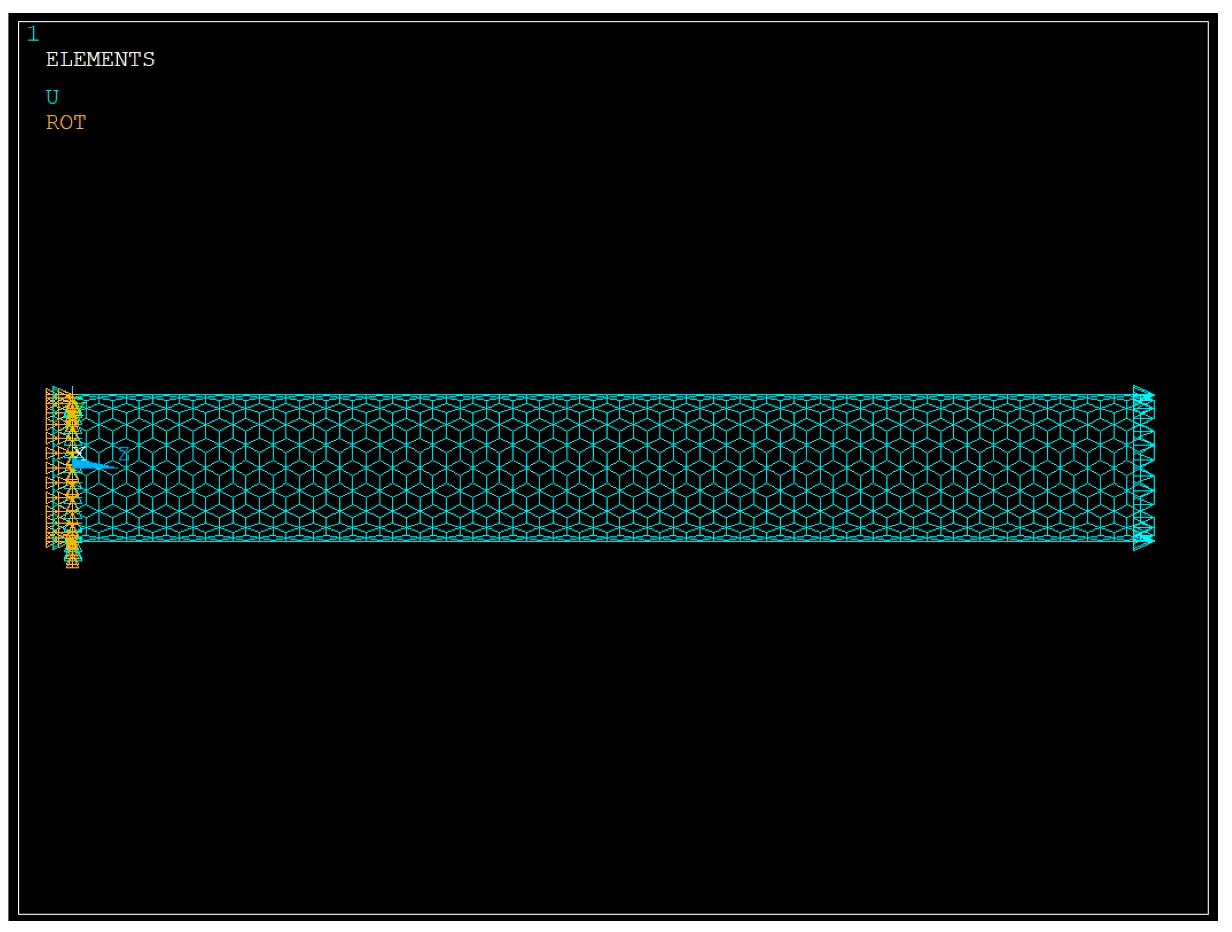
  • Armchair and zigzag single-walled carbon nanotubes (SWCNTs) with a length of 10 nm were modeled using the Nanotube Builder plugin in Visual Molecular Dynamics (VMD).
  • The atomic coordinate files generated in VMD were used to create a finite element mesh by importing the data into MATLAB (Version: 24.2.0.2871072, MathWorks Inc., Natick, MA, USA) [20], where nodes and beam elements were constructed.
  • For finite element analysis, the BEAM188 element type was employed, which is suitable for modeling slender structural components with axial, bending, and torsional stiffness.
  • In the simulation setup, all degrees of freedom at one end of the nanotube were fully constrained, while a displacement corresponding to 10% of the nanotube’s length was applied at the opposite end along the axial (z) direction.
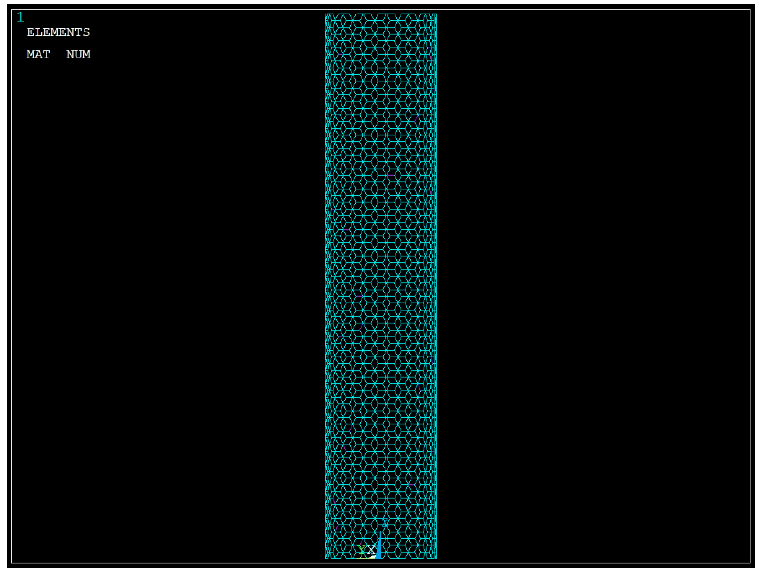
  • To investigate the mechanical behavior of defective CNTs, random point defects were introduced by removing 1% of the total number of beam elements from the model. All other modeling and boundary conditions remained consistent with the pristine case.
  • Recognizing that the spatial positioning of defects can significantly influence stress concentrations and mechanical behavior, multiple defect configurations were examined by systematically varying the defect locations. The resulting mechanical responses exhibited consistent and reproducible trends across all configurations.
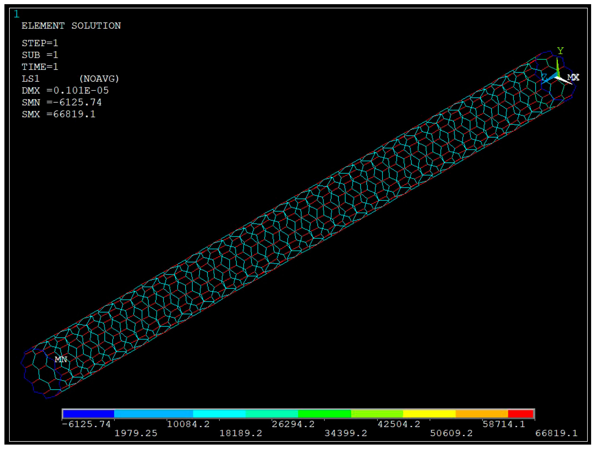
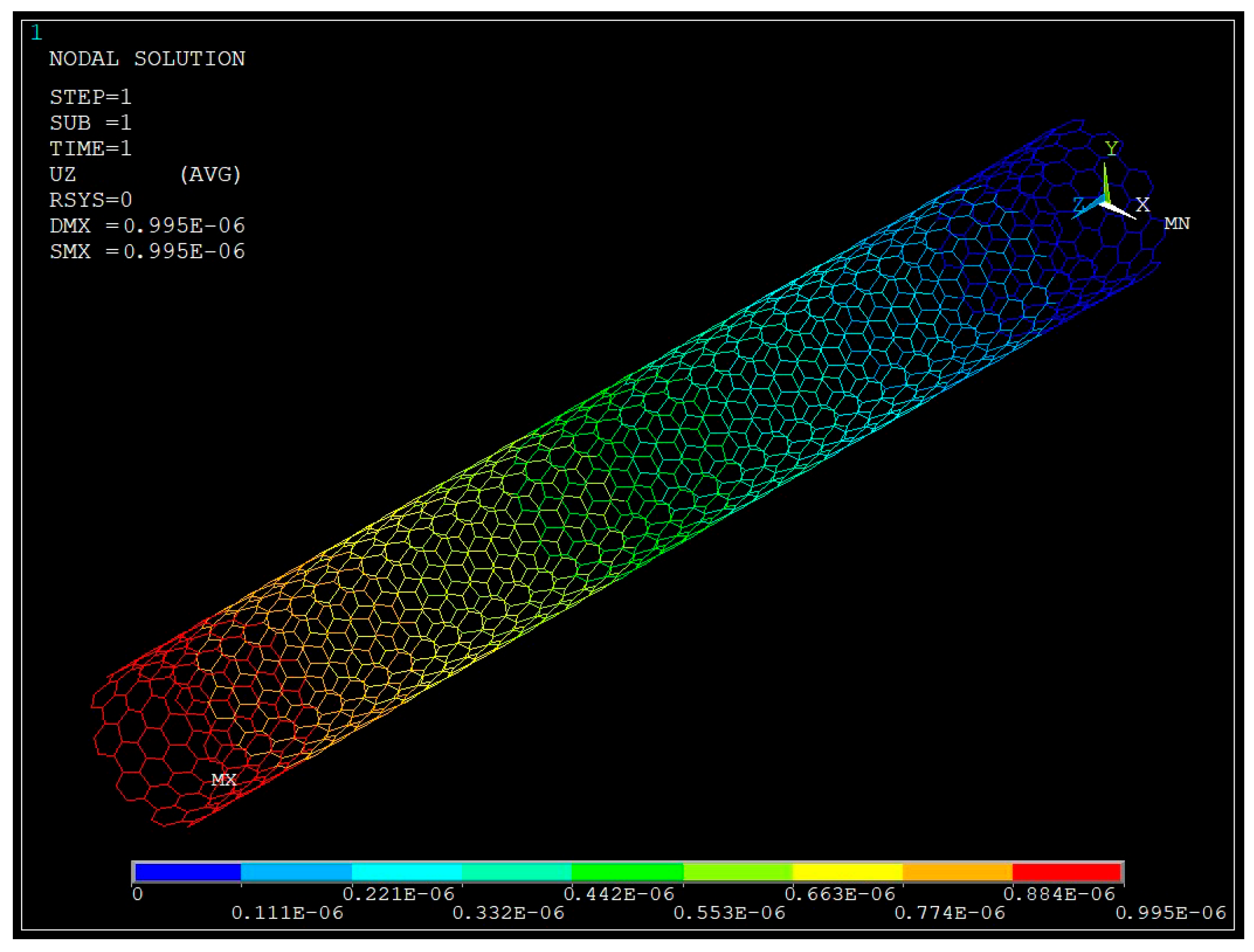
4.2. Results

An axial displacement equivalent to 10% of the nanotube length was applied at one end of the CNT along the z-direction, while the opposite end was held fixed to simulate uniaxial tensile loading. With the nanotube length kept constant across all configurations, the resulting stress on the end nodes was calculated to evaluate the mechanical response as a function of chirality. Figure 8, Figure 9, Figure 10 and Figure 11 illustrate various intermediate stages of the finite element method (FEM) analysis performed on the CNT models.
The stress values are calculated by the following Equation (2):
σ = F z A
where ∑Fz is the sum of forces acting on nodes in z-direction and A is the elemental area on which the force is acting.
Table 3 presents the stress values experienced by the elements of both defective and non-defective carbon nanotubes (CNTs) across different chiralities. These stresses correspond to the forces acting on the covalent carbon–carbon (C–C) bonds, and the values obtained are consistent with previously reported data in the literature [21]. Notably, a greater percentage reduction in bond stress is observed for zigzag CNTs compared to their armchair counterparts. This trend is consistent with the variations in Young’s modulus obtained from molecular dynamics simulations, as reported in Table 2, further validating the influence of chirality and defect presence on the mechanical behavior of CNTs.

5. Conclusions

The results demonstrate that pristine CNTs exhibit superior stiffness and strength due to the continuity of their sp2-hybridized hexagonal lattice, which enables efficient stress transfer. In contrast, the introduction of vacancy defects significantly degrades mechanical performance by disrupting this atomic network. This degradation is more pronounced in larger-diameter CNTs, where defect-induced stress concentrations facilitate local instabilities. Notably, smaller-diameter CNTs of the armchair type showed greater resistance to mechanical failure, even in the presence of defects. The observed reduction in mechanical properties aligns well with previous computational and experimental findings, validating the robustness of the simulation framework.
A key contribution of this work is the integration of MD and FEM analyses to enable a multiscale evaluation of CNT mechanical behavior. By idealizing the atomic structure as a space frame of elastic beam elements representing covalent bonds, the FEM model provided a computationally efficient and scalable method for predicting mechanical response. The close agreement between stress values obtained from the FEM model and atomistic simulations further confirms the validity of this multiscale strategy.
These findings have important implications for the design of CNT-based nanocomposites and nanoelectromechanical systems (NEMS), particularly in applications where defect tolerance and structural reliability are critical. However, the current study is limited to idealized vacancy defects under quasi-static loading conditions and does not consider temperature effects or dynamic loading. Future research may expand this work by incorporating more complex defect types, using varying environmental conditions, and employing experimental validation to enhance the predictive capabilities of the multiscale framework.

Author Contributions

Conceptualization, N.S.M. and A.D.K.; methodology, A.D.K.; software, N.S.M.; validation, N.S.M. and A.D.K.; formal analysis, N.S.M.; investigation, N.S.M.; resources, A.D.K.; data curation, N.S.M.; writing—original draft preparation, N.S.M.; writing—review and editing, N.S.M.; visualization, N.S.M.; supervision, A.D.K. All authors have read and agreed to the published version of the manuscript.

Funding

This research received no external funding.

Data Availability Statement

Data if required can be provided upon request from the corresponding author.

Acknowledgments

This work was performed in whole/part at the Joint School of Nanoscience and Nanoengineering, a member of the National Nanotechnology Coordinated Infrastructure (NNCI), which is supported by the National Science Foundation (Grant ECCS-2025462).

Conflicts of Interest

The authors declare no conflicts of interest.

Abbreviations

The following abbreviations are used in this manuscript:
CNTCarbon Nanotube
VMDVisual Molecular Dynamics
LAMMPSLarge-Scale Atomic/Molecular Massively Parallel Simulator
NVTCanonical Ensemble
FEMFinite Element Method

References

  1. Iijima, S. Helical microtubules of graphitic carbon. Nature 1991, 354, 56–58. [Google Scholar] [CrossRef]
  2. Allotropes of Carbon. Available online: https://edu.rsc.org/infographics/allotropes-of-carbon/4012885.article (accessed on 19 February 2025).
  3. Wilder, J.W.G.; Venema, L.C.; Rinzler, A.G.; Smalley, R.E.; Dekker, C. Electronic structure of atomically resolved carbon nanotubes. Nature 1998, 391, 59–62. [Google Scholar] [CrossRef]
  4. Kelkar, A.D.; Chandekar, G.S.; Mohan, R. Prediction of Material Properties of Single Walled Carbon Nanotube using MD Simulations. In Proceedings of the 2008 8th IEEE Conference on Nanotechnology (NANO), Arlington, TX, USA, 18–21 August 2008; pp. 370–373. [Google Scholar]
  5. Bedi, D.; Sharma, A.; Sharma, S.; Tiwari, S.K. Molecular Dynamics Simulation of Carbon and Boron Nitride nanotubes: Tensile and Compressive Behavior. In IOP Conference Series: Materials Science and Engineering; IOP Publishing: Bristol, UK, 2022; Volume 1248, p. 012101. [Google Scholar]
  6. Sammalkorpi, M.; Krasheninnikov, A.; Kuronen, A.; Nordlund, K.; Kaski, K. Mechanical Properties of Carbon Nanotubes with Vacancies and Related Defects. Phys. Rev. B 2004, 70, 245416. [Google Scholar] [CrossRef]
  7. Charlier, J.C. Defects in carbon nanotubes. Acc. Chem. Res. 2002, 35, 1063–1069. [Google Scholar] [CrossRef] [PubMed]
  8. Collins, P.G. Defects and disorder in carbon nanotubes. Oxford handbook of nanoscience and technology: Materials: Structures, properties and characterization. Techniques 2010, 2, 31. [Google Scholar]
  9. Plimpton, S. Fast parallel algorithms for short-range molecular dynamics. J. Comput. Phys. 1995, 117, 1–19. [Google Scholar] [CrossRef]
  10. Humphrey, W.; Dalke, A.; Schulten, K. VMD: Visual molecular dynamics. J. Mol. Graph. 1996, 14, 33–38. [Google Scholar] [CrossRef] [PubMed]
  11. Dresselhaus, M.S.; Dresselhaus, G.; Saito, R. Physics of carbon nanotubes. Carbon 1995, 33, 883–891. [Google Scholar] [CrossRef]
  12. Stuart, S.J.; Tutein, A.B.; Harrison, J.A. A reactive potential for hydrocarbons with intermolecular interactions. J. Chem. Phys. 2000, 112, 6472–6486. [Google Scholar] [CrossRef]
  13. Yao, N.; Lordi, V. Young’s modulus of single-walled carbon nanotubes. J. Appl. Phys. 1998, 84, 1939–1943. [Google Scholar] [CrossRef]
  14. Bao, W.; Zhu, C.; Cui, W. Simulation of Young’s modulus of single-walled carbon nanotubes by molecular dynamics. Phys. B Condens. Matter 2004, 352, 156–163. [Google Scholar] [CrossRef]
  15. Treacy, M.M.J.; Ebbesen, T.W.; Gibson, J.M. Exceptionally high Young’s modulus observed for individual carbon nanotubes. Nature 1996, 381, 678–680. [Google Scholar] [CrossRef]
  16. Rashko, M.N.; Hamad, S.M.; Barzinjy, A.A.; Hamad, A.H. Mechanical properties of carbon nanotubes (CNTs): A review. Eurasian J. Sci. Eng. 2022, 8, 54–68. [Google Scholar]
  17. Zhang, D.; Zhang, J. Anisotropic mechanical properties of S-graphene nanotubes: Influence of chirality, temperature, number of walls, and defects. Micro Nanostruct. 2025, 205, 208172. [Google Scholar] [CrossRef]
  18. Rafiee, R.; Mahdavi, M. Molecular dynamics simulation of defected carbon nanotubes. Proc. Inst. Mech. Eng. Part L J. Mater. Des. Appl. 2015, 230, 654–662. [Google Scholar] [CrossRef]
  19. Ansys® Mechanical Enterprise Academic Student, Release 24.1.; ANSYS Mechanical APDL: Taipei, China, 2024.
  20. MATLAB, Version: 24.2.0.2871072 (R2024b); MathWorks, Inc.: Natick, MA, USA, 2024.
  21. Ashby, M.; Shercliff, H.; Cebon, D. Materials Engineering, Science, Processing and Design; Butterworth-Heinemann: Oxford, UK, 2014. [Google Scholar]
Figure 1. Formation of chiral vector.
Applnano 06 00012 g001
Figure 2. Tensile loading applied along the arrow direction in (a) Armchair nanotube, (b) Zigzag nanotube.
Applnano 06 00012 g002
Figure 3. CNT with vacancy (circled red) defect.
Applnano 06 00012 g003
Figure 4. Stress–Strain curve for Non-Defective CNT.
Applnano 06 00012 g004
Figure 5. Stress–Strain curve for Defective CNT.
Applnano 06 00012 g005
Figure 6. Ultimate Stress vs. Chirality for Armchair CNT’s. (Note: Armchair-type CNTs with chiralities ranging from (3,3) to (15,15) have been plotted, where the x-axis index represents the chirality configuration—index 1 corresponds to (3,3) and index 13 corresponds to (15,15)).
Applnano 06 00012 g006
Figure 7. Relationship between vacancy density and Young’s modulus for (5,5) CNT (where index 1 corresponds to 0% vacancy and index 4 corresponds to a 3% vacancy density).
Applnano 06 00012 g007
Figure 8. Loads applied on the nodes of (10,10) non-defective CNT.
Applnano 06 00012 g008
Figure 9. Elements representing 1% defects (in violet) in (15,15) armchair CNT.
Applnano 06 00012 g009
Figure 10. FEM analysis of (10,0) zig-zag type CNT.
Applnano 06 00012 g010
Figure 11. FEM analysis of (10,10) armchair CNT.
Applnano 06 00012 g011
Table 1. Ultimate Stress and Strain of CNT with different chirality.
Nanotube.
(n,m)
Without DefectWith Defect
Stress (GPa)StrainStress (GPa)Strain
(5,0)203.500.1924.600.20
(10,0)183.130.2185.240.20
(15,0)143.400.22128.200.21
(5,5)536.310.36169.190.33
(10,10)282.600.36163.200.39
(15,15)190.540.36155.320.33
Table 2. Young’s Modulus values.
Nanotube (n,m)Young’s Modulus (TPa)
Non-DefectiveDefective
(5,0)1.490.29
(10,0)1.200.72
(15,0)0.920.91
(5,5)1.550.41
(10,10)0.820.43
(15,15)0.550.44
Table 3. Stress along z-direction with different chirality.
Nanotube
(n,m)
Fz/A (GPa)% Decrease
Non-DefectiveDefective
(5,0)90.9885.925.56
(10,0)93.8490.413.65
(15,0)94.4190.813.81
(5,5)94.6691.253.60
(10,10)94.6791.653.19
(15,15)94.6792.742.03
Disclaimer/Publisher’s Note: The statements, opinions and data contained in all publications are solely those of the individual author(s) and contributor(s) and not of MDPI and/or the editor(s). MDPI and/or the editor(s) disclaim responsibility for any injury to people or property resulting from any ideas, methods, instructions or products referred to in the content.

