


Abstract
Oil and gas well cement is routinely exposed to aggressive chemical and mechanical environments that can compromise long-term zonal isolation. Conventional Portland cement systems, which rely on hydration products such as calcium silicate hydrate (C–S–H), are particularly vulnerable to acid attack, carbonation, high salinity, and thermal stress. This study investigates a polymer–mineral composite cement in which Class F fly ash is incorporated into an epoxy resin matrix at 0, 25, and 50 weight percent (wt%) loading. The composite samples were exposed for ten days to harsh downhole-representative environments, including hydrochloric acid (HCl, 15–28 wt%), sodium hydroxide (NaOH, 15–28 wt%), sodium chloride (NaCl) brines (20 wt%), crude oil, elevated temperatures up to 100 °C, and high-pressure carbon dioxide (CO2). Compressive strength was evaluated using a universal testing machine, capturing both deformation strength and ultimate failure strength to assess elastic and structural performance. Across most conditions, the composite maintained strengths exceeding 5000 psi, demonstrating strong chemical resistance. Acidic and CO2 exposures primarily reduced elastic deformation rather than ultimate strength, suggesting localized interaction with the polymer matrix. Elevated temperature reduced strength to ~2800 psi and diminished elasticity, marking the material’s upper thermal limit. Acetone exposure progressively degraded the polymer network, highlighting potential controlled removability. These findings indicate that embedding industrial fly ash in a polymer matrix produces a mechanically resilient and chemically robust cement alternative with up to 50 wt% industrial waste incorporation. This hybrid system offers a promising approach for wells exposed to acidic, CO2-rich, or high-salinity environments, where conventional Portland cement may fail.
1. Introduction
Cementing is one of the most critical operations in the life cycle of an oil or gas well. Beyond securing the casing, well cement serves as the primary barrier that ensures zonal isolation, prevents fluid migration, and protects freshwater aquifers from contamination. Loss of cement integrity can result in sustained casing pressure, interzonal communication, or, in severe cases, catastrophic failure. Historical well integrity incidents have repeatedly demonstrated that cement failure is not merely a materials issue, but a systemic risk to operational safety and environmental protection. Research has addressed chemical formulations for cement slurries and the mechanical behavior of well materials under stress [1,2,3], the influence of various fluids on rock and cement properties [4,5,6,7,8], and advanced imaging or characterization techniques for pore structures and erosion testing [5,6,7,8,9,10,11]. Additionally, novel methods such as in situ gravel packs and polymer injection strategies have been explored to improve operational efficiency and promote sustainability in oil and gas wells [7,8,9,10,11,12,13,14,15,16,17,18,19].
The downhole environment presents a uniquely complex combination of stressors. Cement sheaths are exposed to fluctuating mechanical loads resulting from casing expansion and contraction, pressure cycling during production and injection, and long-term reservoir depletion effects. Chemically, the cement may encounter acidic fluids, carbon dioxide, hydrogen sulfide, high salinity brines, and crude oil components [20,21,22,23,24,25]. Thermally, elevated temperatures accelerate degradation mechanisms and induce thermal stresses that can generate microcracks [26,27,28]. Moreover, mechanical and hydraulic challenges such as fracture height growth, fracture propagation, and leakoff effects can exacerbate cement and formation integrity issues [13,14,16,19]. Conventional Portland cement systems, which rely on hydration products such as calcium silicate hydrate (C–S–H), are particularly susceptible to acid dissolution, carbonation, shrinkage, and reduced long-term durability under such complex downhole conditions [15,16,17,18,21,22,23,27].
To address these limitations, alternative cement systems have been investigated. Geopolymer cements derived from fly ash and alkaline activators have demonstrated improved chemical resistance and reduced carbon footprint. However, their performance remains sensitive to fly ash variability and activator composition, leading to concerns regarding reproducibility and field reliability [29,30,31,32,33]. Polymer-based materials, particularly epoxy resins, have also been used in well remediation, sand consolidation, and coating applications due to their chemical resistance and high mechanical strength. Nevertheless, polymer systems are typically deployed as repair materials rather than primary cementing systems [34,35,36,37,38,39,40,41,42].
The present study explores a different approach: the development of a hybrid polymer–mineral composite in which fly ash particles are embedded within an epoxy matrix. In this configuration, the polymer phase provides chemical resistance and elasticity, while the mineral filler reduces material cost and enhances stiffness [43,44,45,46,47,48,49,50,51,52,53,54,55]. Unlike geopolymer systems, this composite does not rely on hydration chemistry, thereby eliminating acid-sensitive cementitious phases. At the same time, incorporating up to 50 wt% fly ash improves sustainability by valorizing industrial waste material [56,57,58,59,60,61].
Despite extensive research on geopolymer cements and polymer-based well remediation materials, there remains a lack of systematic evaluation of hybrid polymer–mineral composite systems as primary cementing alternatives for chemically aggressive well environments. Conventional Portland cement systems are inherently vulnerable to acid dissolution, carbonation reactions, and microcracking under cyclic mechanical loading. While additives can improve specific properties, they do not fundamentally alter the calcium-based hydration chemistry governing degradation mechanisms [62,63,64,65,66,67,68,69,70].
Previous studies have investigated epoxy resins primarily for sand consolidation, casing repair, or remedial sealing operations rather than as structural cement matrices incorporating mineral fillers. Furthermore, most reported studies evaluate isolated exposure conditions rather than simultaneous benchmarking across acidic, alkaline, saline, thermal, and CO2-rich environments relevant to oil and gas operations [70,71,72,73,74,75,76,77,78,79,80,81,82,83,84,85,86,87,88].
The objective of this research is to systematically evaluate the mechanical durability and chemical resilience of a fly ash–epoxy composite under aggressive downhole conditions, including acidic, alkaline, high-salinity, CO2-rich, thermal, and pressurized environments typical of oil and gas wells. Particular emphasis is placed on distinguishing between elastic deformation strength, the material’s capacity to sustain loads without permanent deformation, and ultimate failure strength, providing a more complete characterization of the material’s load-bearing behavior. By assessing performance across multiple extreme conditions, this study aims to define the operational envelope and identify potential applications for this composite cement system.
This study addresses several gaps in current cementing and resin-based systems by:
- Developing a hybrid fly ash–epoxy composite that incorporates up to 50 wt% industrial by-product material, thereby promoting resource efficiency and partial replacement of high-energy polymer content.
- Systematically evaluating mechanical durability under a range of chemically aggressive, thermal, and high-pressure conditions that are relevant to wellbore integrity.
- Benchmarking performance against conventional American Petroleum Institute (API) Class G cement, highlighting differences in chemical resistance, ductility, and long-term stability.
- Distinguishing between deformation strength and failure strength, allowing the characterization of semi-ductile behavior that conventional cement tests often fail to capture.
While epoxy resins have been widely applied in well repair, sand consolidation, and temporary plugging, the present composite system is distinct in both design and performance. Unlike conventional resin-based materials, this fly ash–epoxy system leverages industrial by-products to achieve a mechanically resilient, chemically stable matrix that can partially replace high-energy polymer without sacrificing performance [7,88]. Compared with geopolymer cement systems, which rely on alkali activation of aluminosilicate precursors, the epoxy–fly ash composite provides superior resistance to acid, CO2, and high-salinity conditions commonly encountered in aggressive reservoirs [67,77,84,86,88]. This unique combination of semi-ductile mechanical behavior, chemical resistance, and waste material incorporation positions the composite as a novel alternative for specialized applications such as acidizing-prone wells, CO2 injection projects, and high-salinity formations, where traditional Portland cement or geopolymer systems may exhibit accelerated degradation.
By defining the operational envelope, performance trade-offs, and environmental advantages of this composite system, the study contributes to the development of next-generation cementing materials tailored for chemically aggressive, CO2-intensive, and thermally constrained well environments.
2. Experimental Description
2.1. Materials
2.1.1. Fly Ash
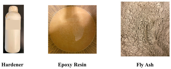
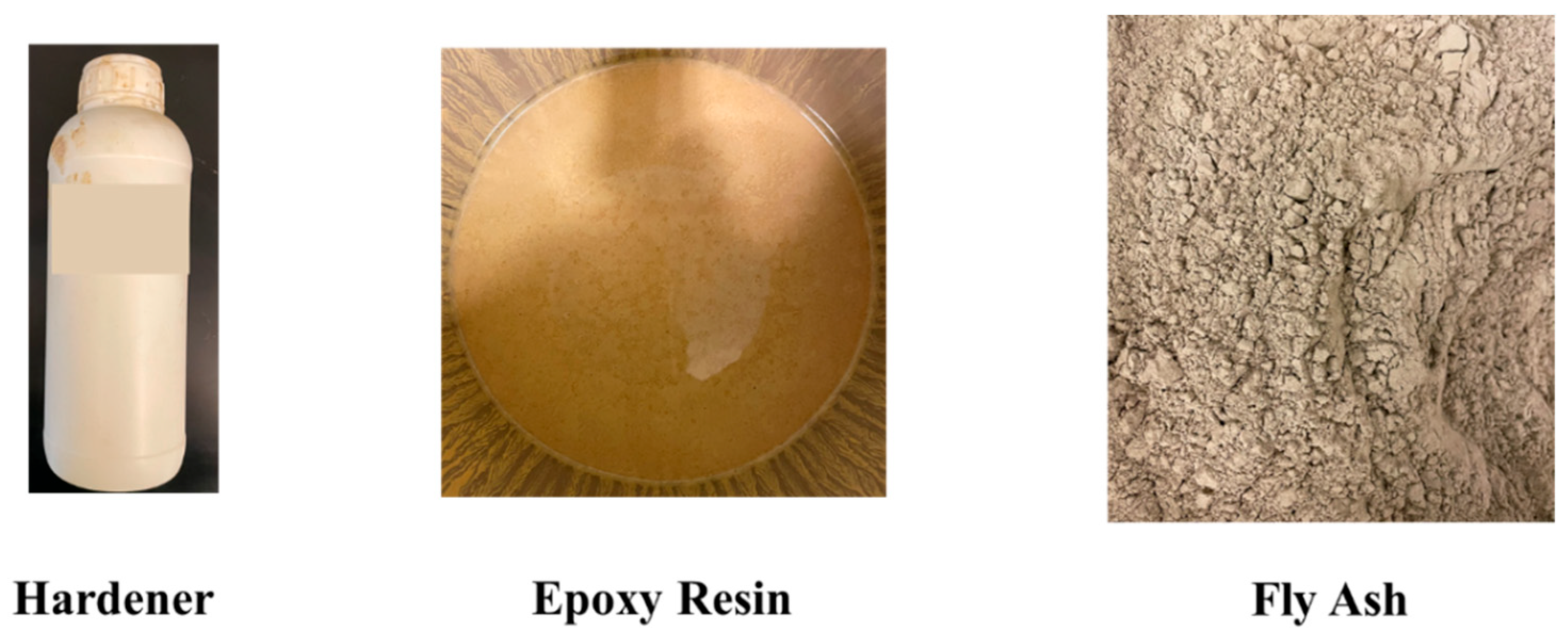
Class F fly ash was used as the mineral filler phase in the composite cement. The material was obtained from a cement production facility in Egypt. Class F fly ash was selected due to its low calcium content and chemical stability, which reduces the likelihood of secondary hydration or acid-reactive phases forming within the composite [84,85,86,87]. Prior to mixing, the fly ash was oven-dried at 60 °C for 24 h to eliminate moisture that could interfere with polymer curing. The chemical composition of Class F fly ash used in this research:
- Silicon dioxide (SiO2): 50–60 wt%—major glassy phase contributing pozzolanic activity;
- Aluminum oxide (Al2O3): 20–30 wt%—provides pozzolanic properties;
- Iron oxide (Fe2O3): 5–10 wt%—minor component; can influence color and reactivity;
- Calcium oxide (CaO): <10 wt% (usually 1–5)—low calcium content distinguishes Class F from Class C fly ash;
- Magnesium oxide (MgO): 1–5 wt%—can affect minor expansion;
- Sulfur trioxide (SO3): <1–3 wt%—depends on coal and cement kiln source;
- Alkalis (Na2O + K2O): 0.5–3 wt%—low levels preferred to reduce alkali-silica reaction risk;
- Loss on ignition (LOI, unburned carbon): 1–6 wt%—higher LOI can reduce workability and affect polymer bonding.
2.1.2. Epoxy Resin System
A commercially available two-component epoxy system consisting of a base resin and amine hardener was used as the polymer matrix. The resin was supplied as a moderately viscous, light-yellow liquid, while the hardener was a low-viscosity transparent liquid. The manufacturer-recommended resin-to-hardener ratio was strictly maintained to ensure complete crosslinking and consistent mechanical performance. The ratio of epoxy resin to hardener was 4:1 by weight.
The epoxy system was selected due to:
- High compressive strength after curing;
- Chemical resistance to acids and brines;
- Low permeability;
- Proven use in downhole repair and consolidation operations.
2.1.3. Chemical Exposure Media
To simulate aggressive downhole environments, the following exposure fluids were prepared:
- Hydrochloric acid (15 wt% and 28 wt%);
- Sodium hydroxide solution (15 wt% and 28 wt%);
- Sodium chloride brine (15 wt% and 20 wt%);
- Distilled water (baseline control);
- Crude oil (450 cp at ambient conditions, Gulf of Suez origin);
- Carbon dioxide (500 psi and 1200 psi at 60 °C);
- Acetone (for degradation study).
All chemical solutions were prepared using analytical-grade reagents and distilled water.
2.2. Composite Cement Preparation
The composite cement consisted of epoxy resin as the continuous matrix phase and fly ash as the dispersed filler phase. Three formulations were prepared:
- 0 wt% fly ash (pure epoxy control);
- 25 wt% fly ash;
- 50 wt% fly ash.
Fly ash loading was selected to investigate the effect of mineral filler content on strength retention and elastic behavior while maintaining workability. Increasing the fly ash concentration beyond 50% by weight resulted in a significant decrease in sample workability. This had a negative impact on the slurry viscosity which made it almost impossible to inject. Also, increasing the fly ash concentration resulted in a significant increase in the slurry density, which also impacted workability and injectivity negatively.
The preparation procedure was as follows:
- The required mass of fly ash was weighed using a precision balance.
- The epoxy resin component was placed in a clean mixing container.
- Fly ash was gradually added to the resin under continuous mechanical stirring to ensure homogeneous dispersion and prevent agglomeration.
- After achieving uniform particle distribution, the hardener was added according to the manufacturer’s specified ratio.
- The mixture was stirred for an additional 3–5 min to ensure complete blending.
- The slurry was poured into cubic molds (dimensions: 5 × 5 × 5 cm3).
- Samples were allowed to cure at ambient laboratory conditions for 24 h (22 °C, and 14.7 psia, and 43% humidity).
- After demolding, specimens were conditioned for an additional 48 h prior to exposure testing.
All samples were visually inspected to ensure absence of macro-voids or segregation. The chemicals used are presented in Figure 1.
Figure 1.
Components of Novel Cement.
2.3. Exposure Conditions
To evaluate chemical and thermal durability, cured specimens were fully submerged in the designated exposure media for 10 consecutive days. The conditions under which the evaluation conducted was selected based on industry considerations. The 15% and 28% HCl and NaOH represent the most severe conditions that could be present in hydrocarbon wells. Additionally, the salinity selected was based on the concentrations of the formation water associated with oil and gas wells, which can reach more than 25 wt%. Finally, the temperature and CO2 were selected based on different reservoir temperatures and the pressures required to represent gaseous CO2 and supercritical CO2 phases.
Exposure conditions included:
- Acidic environment (15% and 28% HCl);
- Alkaline environment (15% and 28% NaOH);
- High salinity brine (15% and 20% NaCl);
- Elevated temperature (20, 40, 60, 100 °C water bath);
- Carbon dioxide at 60 °C under:
- ➢
- 500 psi (gaseous CO2);
- ➢
- 1200 psi (supercritical CO2);
- Crude oil at ambient conditions;
- Acetone for degradation testing.
During exposure:
- Samples were visually inspected daily.
- Mass measurements were recorded to monitor fluid uptake or degradation.
- For CO2 experiments, samples were placed inside a sealed high-pressure vessel equipped with a pressure regulator.
All exposure durations were maintained at 10 days to ensure consistent comparative evaluation across environments.
2.4. Compressive Strength Testing
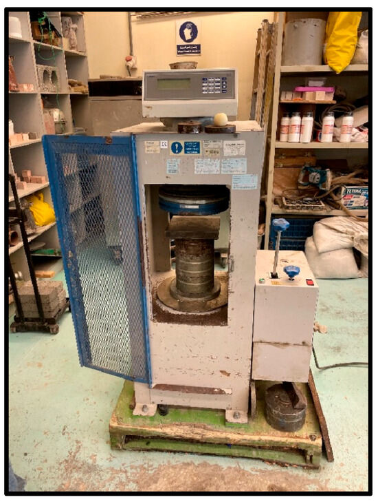
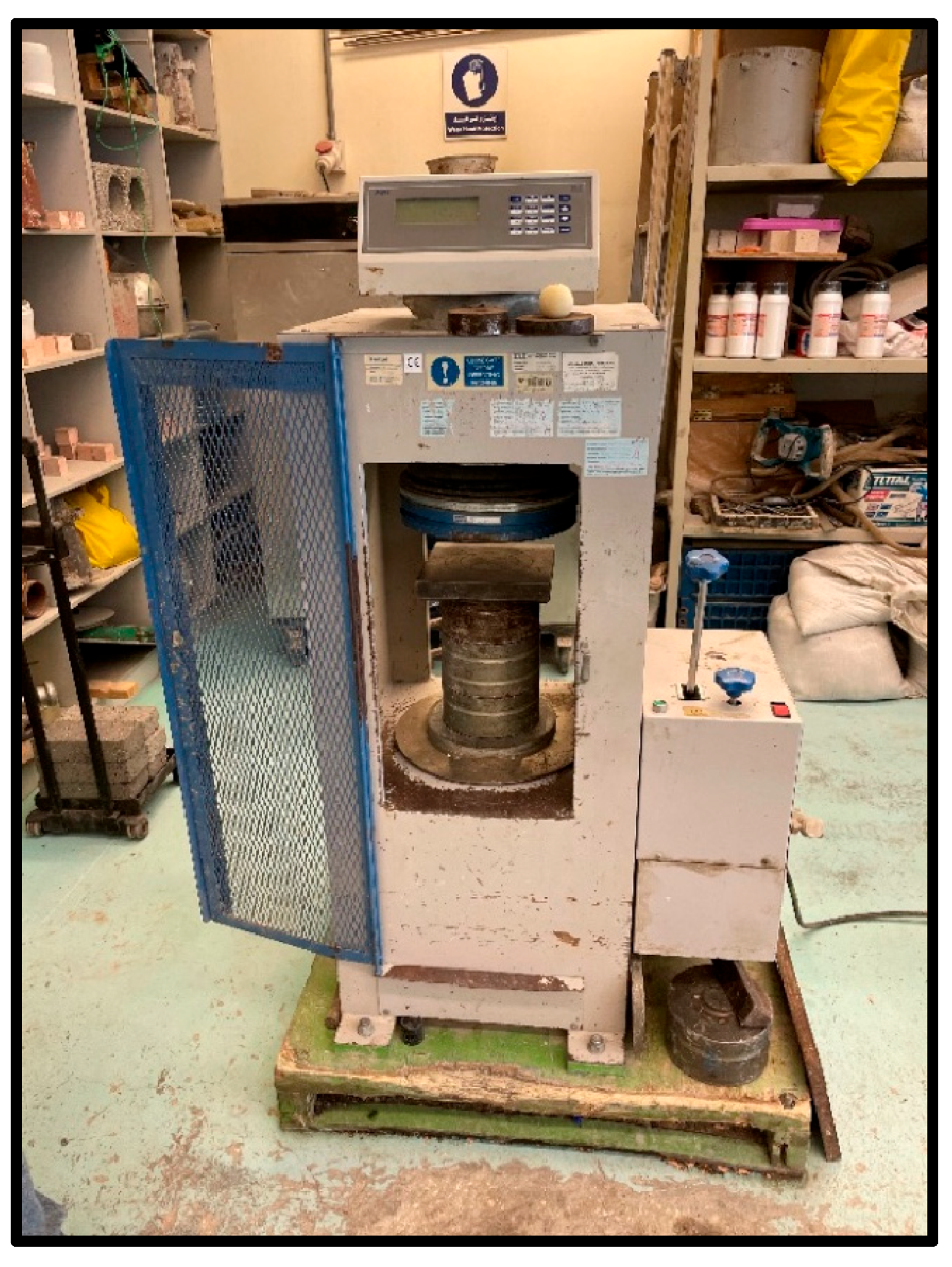
Compressive strength was measured using a calibrated universal testing machine (UTM) (obtained from HST, Shanghai, China). Each formulation and exposure condition was tested in triplicate to ensure reproducibility. Figure 2 presents the universal testing compressive strength machine. The universal testing compressive was obtained from HST-China strength machine,(obtained from HST, Shanghai, China, used in this research had a capacity of 2000 kN and an accuracy of two decimal places.
Figure 2.
Universal Testing Compressive Strength Machine.
The loading protocol included:
- Axial compressive loading applied at a constant displacement rate of 40 kgf/cm2/min.
- Load continuously recorded until structural failure.
Because the composite exhibited significant elastic deformation prior to fracture, two strength metrics were defined:
- Deformation Strength—The stress at the onset of noticeable macroscopic deformation. The point at which the deformation strength was determined was when the sample exhibited plastic deformation, but did not yet fail. It was determined as the yield point of the sample from the stress–strain plot.
- Failure Strength—The maximum stress recorded immediately prior to structural failure. This was determined as the tensile strength of the samples and was determined from the stress–strain plot.
Compressive strength was calculated based on Equation (1):
where:
- = applied load at deformation or failure (lbf or N)
- = cross-sectional area of the specimen
Results are reported as mean values of three replicates.
2.5. Statistical Considerations
All experiments were conducted using three independent specimens per condition. Average compressive strength values are reported, and variability among samples was monitored to assess homogeneity of mixing. Deviations between replicates remained within acceptable laboratory variation limits, indicating reproducible composite fabrication.
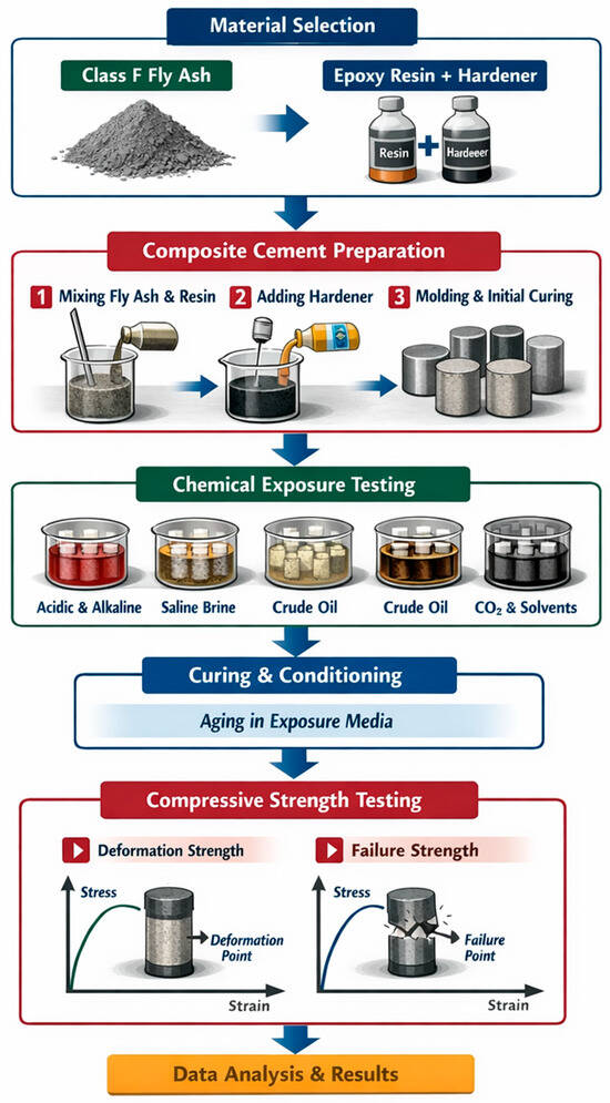
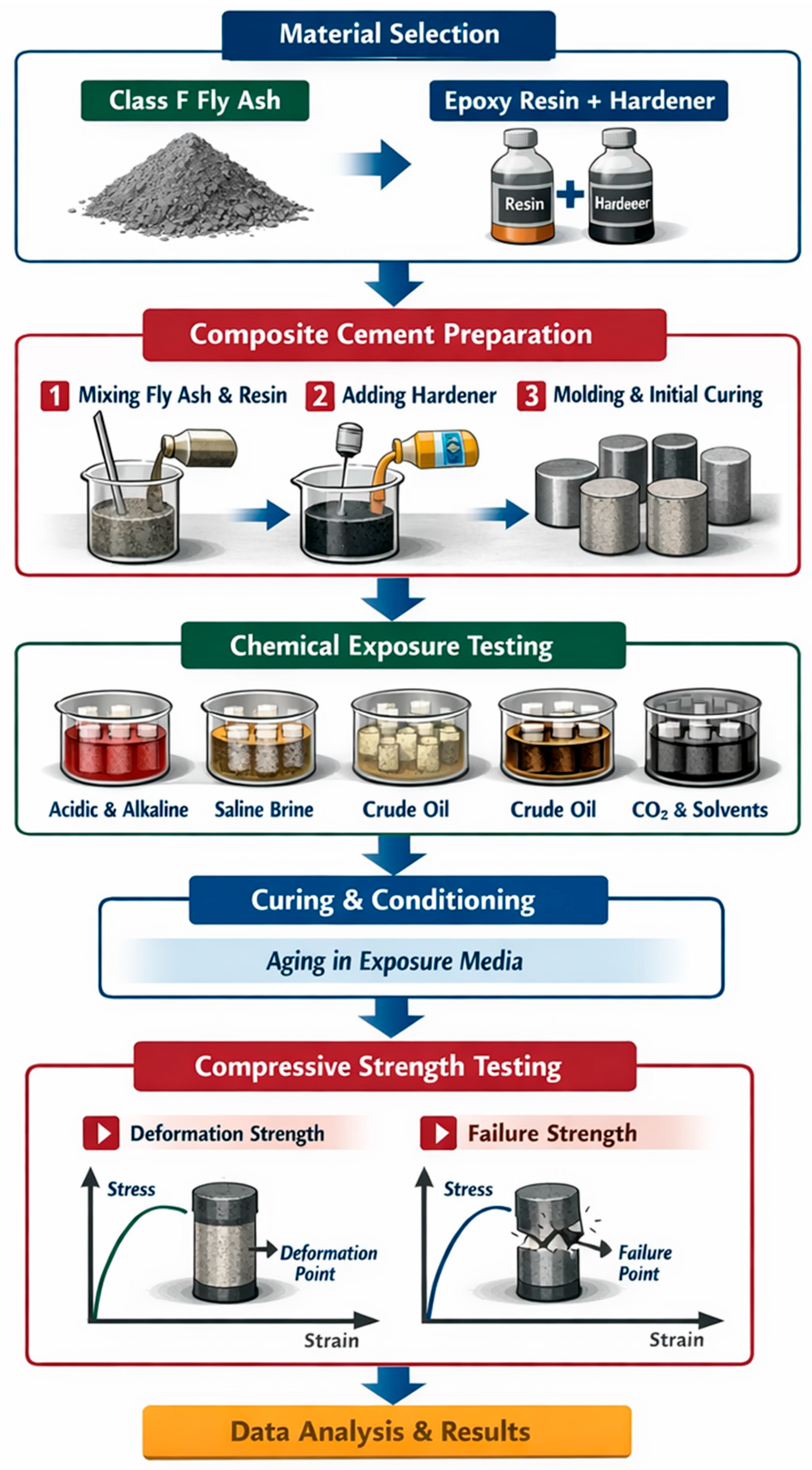
Figure 3 shows an illustration of the experimental workflow and the cement preparation procedure to highlight the exact steps followed to conduct the experiments.
Figure 3.
Experimental Workflow.
3. Results and Analysis
The compressive strength results for both the deformation strength and the failure strength of the novel fly ash resin cement under different conditions is presented. For all conditions, three samples were tested including a sample with no fly ash, a sample with 25% fly ash, and a sample with 50% fly ash. For each experiment three samples were tested and the average compressive strength for all three samples was recorded to ensure that the cement was mixed homogeneously. The tests include acid, alkaline resistance, high salinity, high temperature, high pressure, carbon dioxide, and crude oil resistance. The results also present tests for decomposition of the cement using acetone.
3.1. Baseline Mechanical Performance (Distilled Water Conditioning)
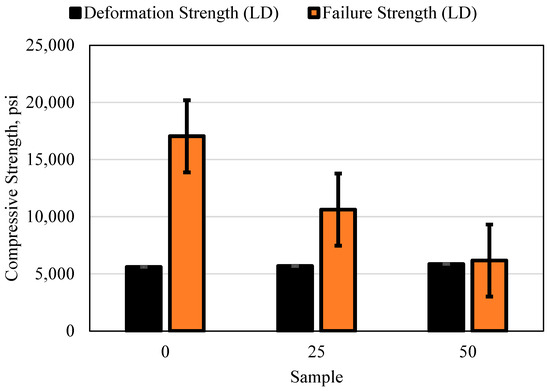
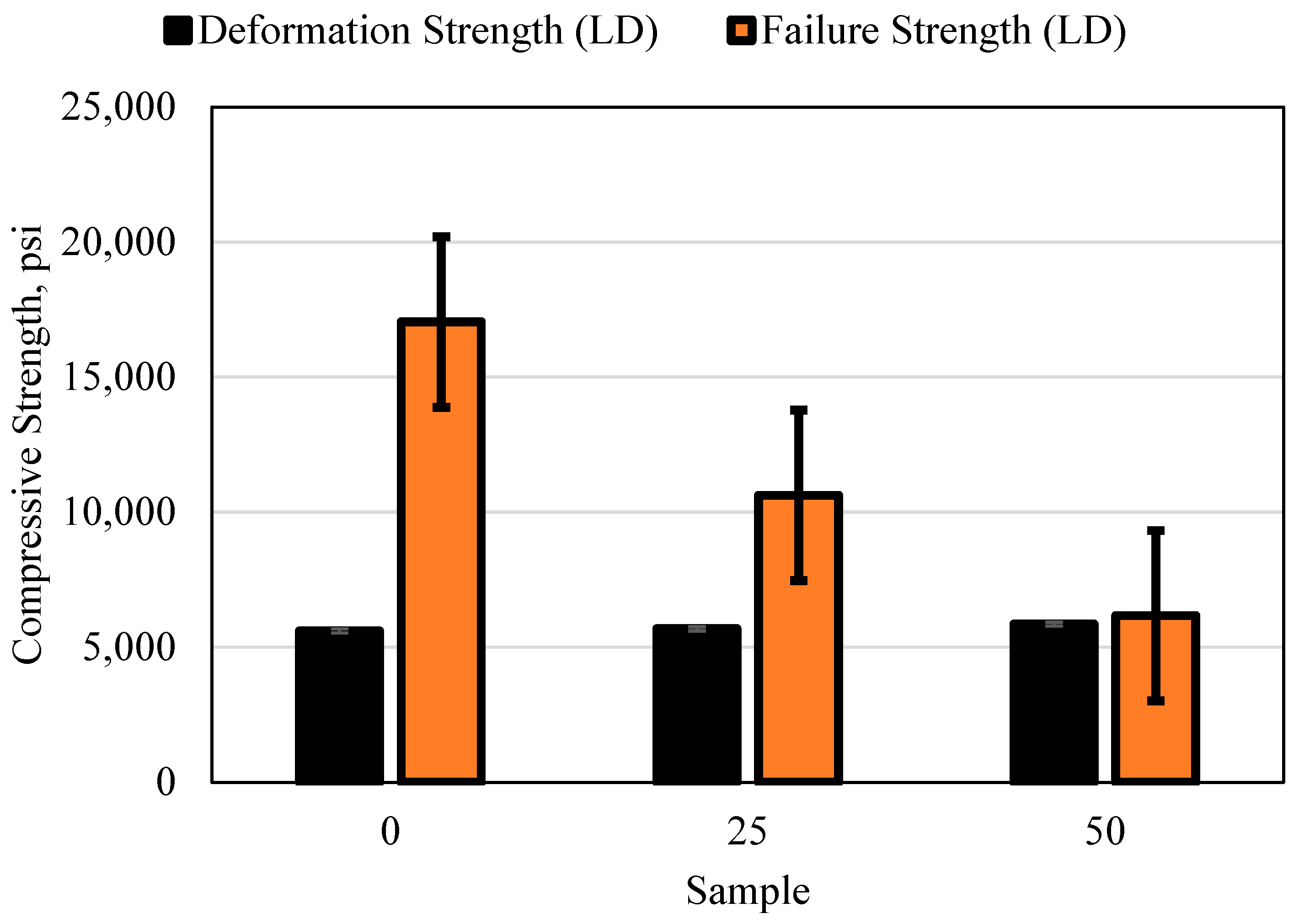
The baseline compressive strength of the composite specimens was evaluated after 10 days of immersion in distilled water to establish a reference for subsequent environmental exposure comparisons, shown in Figure 4.
Figure 4.
Deformation and Failure Strength of the 0, 25, and 50 wt% Fly Ash Samples Placed in Distilled Water for 10 Consecutive Days.
Across all formulations (0, 25, and 50 wt% fly ash), deformation strength remained approximately 5500–5800 psi. The ultimate failure strength, however, exhibited a clear dependence on fly ash content. The 0 wt% sample (pure epoxy matrix) demonstrated the highest failure strength, while increasing fly ash loading progressively reduced ultimate failure stress and reduced elastic deformation prior to fracture.
This behavior reflects the transition from a polymer-dominated ductile response to a more particle-constrained semi-brittle composite response as filler loading increases. The fly ash particles act as rigid inclusions within the polymer matrix, restricting chain mobility and reducing strain capacity before failure.
For comparison, conventional API Class G cement cured under similar laboratory conditions typically exhibits compressive strengths in the range of 3000–5000 psi after 7–14 days, depending on curing temperature and additives. The composite cement therefore meets or exceeds the minimum compressive strength requirements typically specified for primary cementing operations.
Importantly, unlike Portland cement systems that exhibit brittle fracture at peak load, the composite demonstrated measurable deformation prior to structural failure. This ductility may provide tolerance against microcrack propagation caused by casing expansion, thermal cycling, and pressure fluctuations.
3.2. Performance Under Acidic Conditions
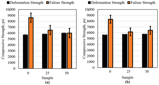
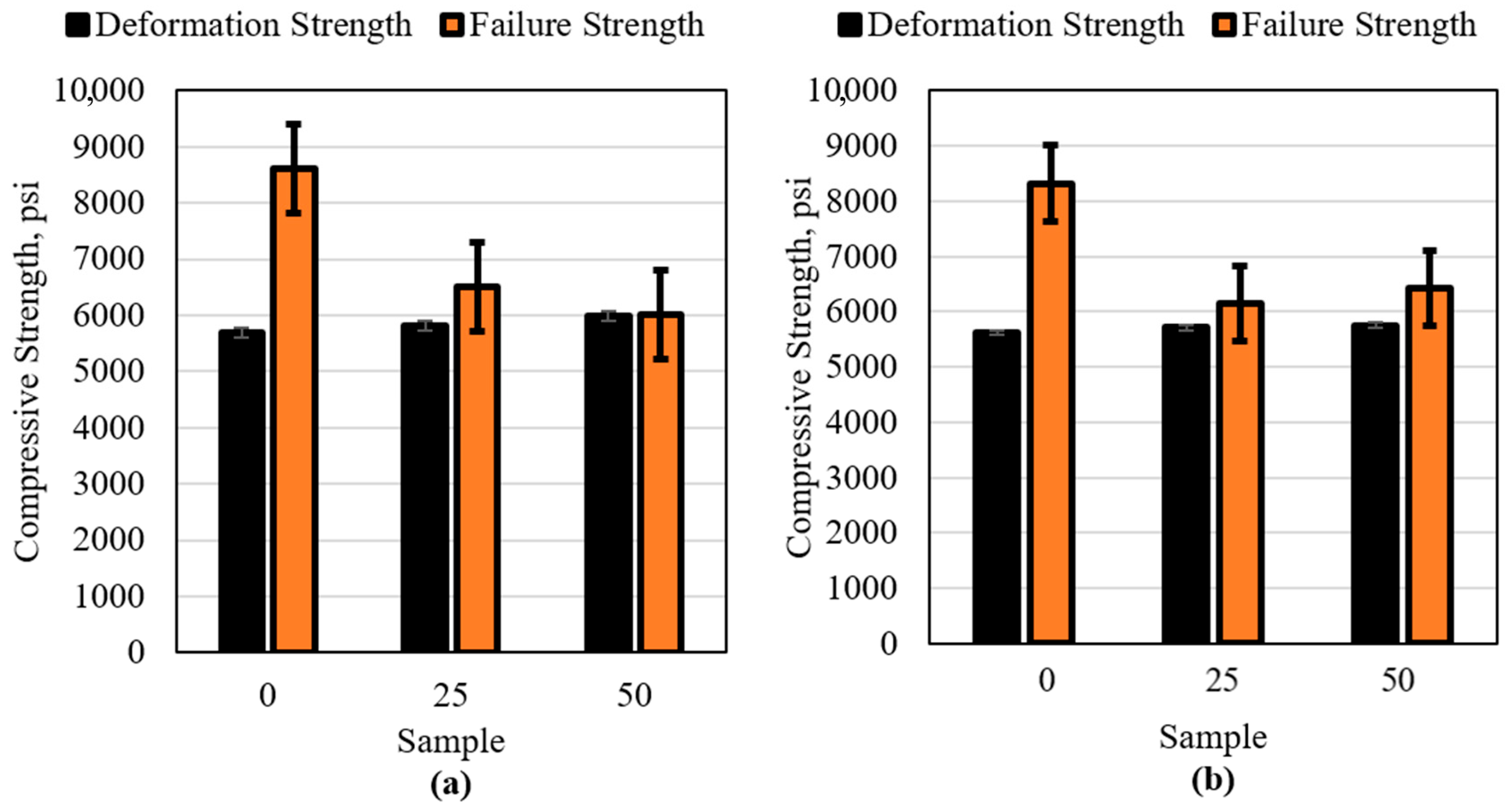
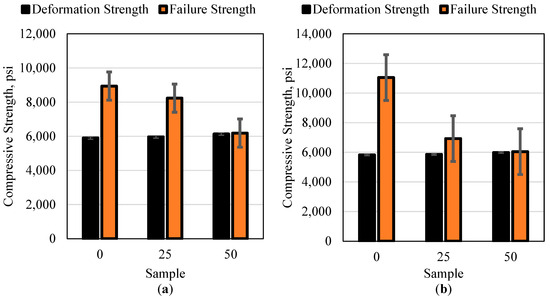
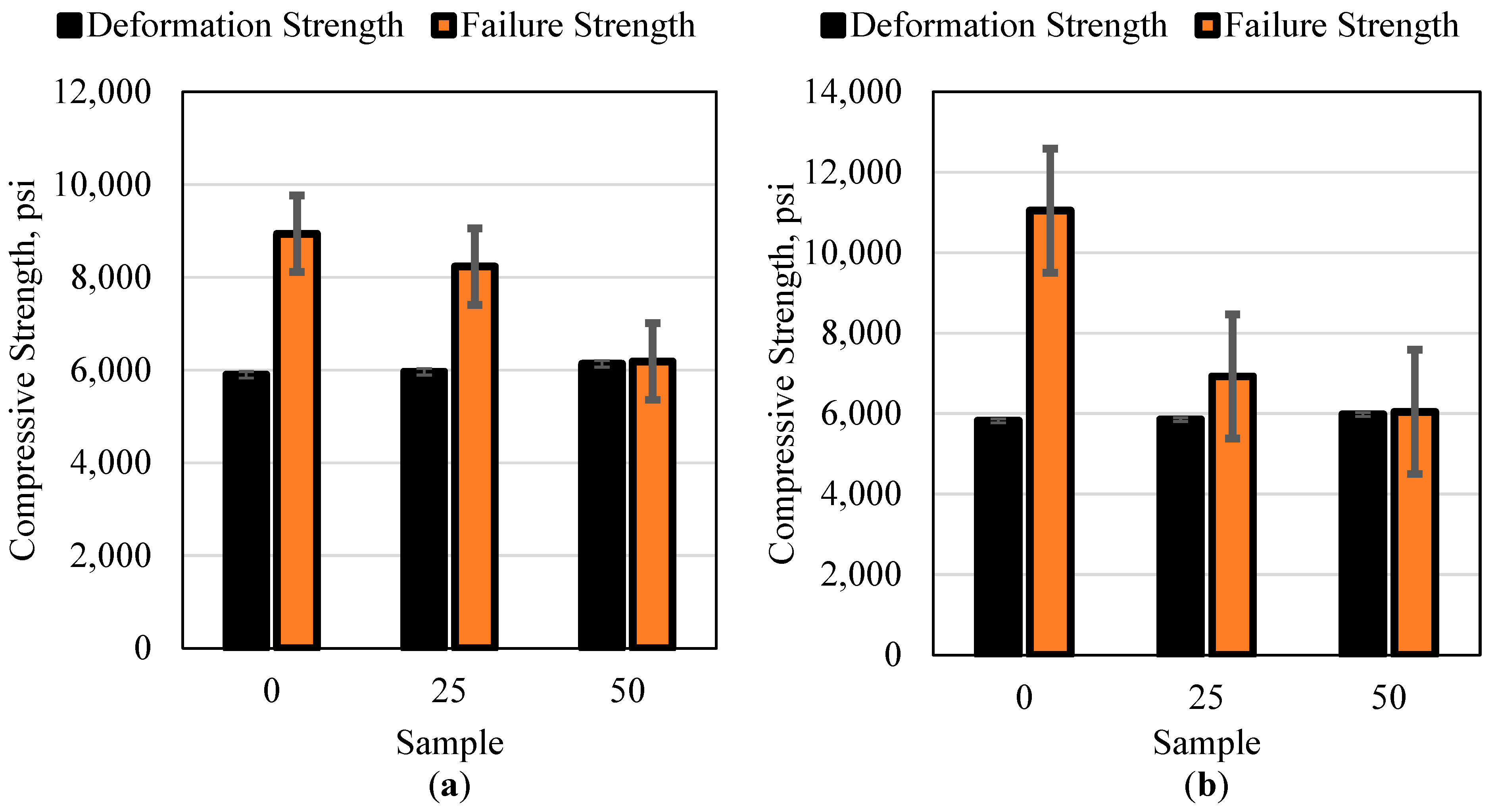
Exposure to 15 wt% and 28 wt% HCl did not significantly reduce ultimate compressive strength for any formulation. Deformation strength remained above 5500 psi across fly ash loadings, with only moderate reductions observed in the pure epoxy formulation, as is shown in Figure 5.
Figure 5.
Deformation and Failure Strength of the 0, 25, and 50 wt% Fly Ash Samples Placed in (a) 15 wt% HCl and (b) 28 wt% HCl for 10 Consecutive Days.
In contrast, conventional Portland cement systems are highly vulnerable to hydrochloric acid exposure due to dissolution of calcium hydroxide and decalcification of C–S–H phases. Even short-term exposure to strong acid can reduce compressive strength by more than 30–60%, depending on concentration and exposure duration.
The composite’s resistance to acid degradation can be attributed to its polymer-based matrix. Because the material does not rely on hydration products or calcium-based binding phases, there are no acid-reactive mineral components susceptible to rapid dissolution. The slight reduction in deformation strength observed in the 0 wt% sample suggests surface-level polymer softening or plasticization rather than structural degradation.
The addition of fly ash appeared to slightly stabilize elastic response under acid exposure, likely due to reduced polymer fraction and increased mechanical confinement of the matrix phase.
The resistance of epoxy–fly ash cement composites to acid degradation is closely tied to how well the solid particles are bonded within the polymer matrix. When strong interfacial bonding exists between the epoxy resin and the fly ash particles, the composite forms a more continuous and tightly integrated structure, which limits the penetration of acidic fluids and slows down chemical attack. This improved bonding reduces microvoids and weak interfaces, typically the first points of acid ingress, thereby enhancing durability. In contrast, weaker bonding leads to interfacial gaps and pathways that allow acids to infiltrate more easily, accelerating degradation and material breakdown. In essence, the better the adhesion within the polymer matrix, the more resistant the composite is to acid-induced damage [81].
Overall, under extreme acid concentrations (28 wt% HCl), the composite maintained compressive strength values exceeding those typically reported for acid-exposed Class G cement systems.
3.3. Alkaline Stability
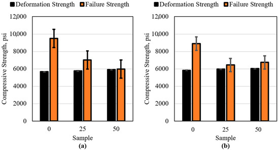
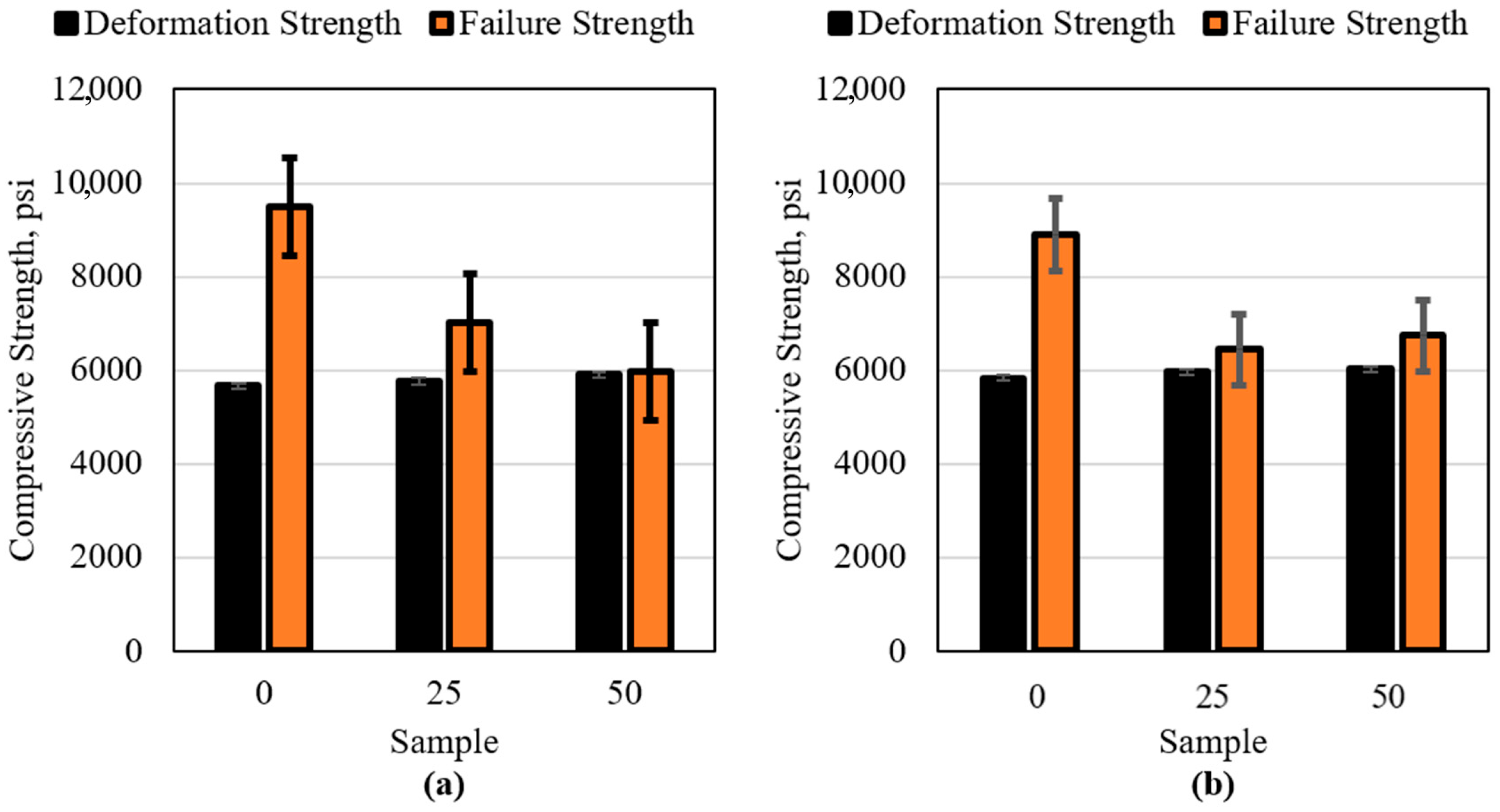
Under high-pH exposure (15 wt% and 28 wt% NaOH), compressive strength remained close to baseline values, with less reduction in deformation strength compared to acid exposure, shown in Figure 6.
Figure 6.
Deformation and Failure Strength of the 0, 25, and 50 wt% Fly Ash Samples Placed in (a) 15 wt% NaOH and (b) 28 wt% NaOH for 10 Consecutive Days.
Epoxy systems are generally resistant to alkaline attack over short exposure periods, although prolonged hydroxide exposure may induce chain scission in some resin systems. The limited impact observed over 10 days suggests that hydroxide diffusion into the crosslinked network was minimal under the test conditions.
Conventional cement systems are inherently alkaline and typically tolerate high-pH exposure; however, extreme alkaline injection fluids used in enhanced oil recovery can still alter cement microstructure over time. The composite system demonstrated mechanical stability under these aggressive alkaline conditions, indicating its potential suitability for chemically enhanced oil recovery wells.
3.4. High Salinity Exposure and Fluid Uptake
Exposure to 15 wt% and 20 wt% NaCl brine resulted in negligible reduction in compressive strength for all formulations, as is evident in Figure 7. However, minor fluid expulsion was observed during compression in some specimens.
Figure 7.
Deformation and Failure Strength of the 0, 25, and 50 wt% Fly Ash Samples Placed in (a) 15 wt% NaCl and (b) 20 wt% for 10 Consecutive Days.
This phenomenon suggests limited brine imbibition into micro voids or interfacial regions between fly ash particles and the polymer matrix. Possible sources of such micro voids include:
- Entrapped air during mixing;
- Incomplete particle wetting;
- Localized filler clustering.
Despite evidence of limited fluid uptake, strength retention indicates that these voids are isolated and non-percolating. In contrast, conventional cement systems possess interconnected pore networks that readily allow brine penetration, salt crystallization, and long-term permeability evolution.
The polymer matrix likely serves as a diffusion barrier, significantly restricting brine transport compared to hydrated cement systems. This characteristic may improve long-term resistance to saline formation water environments.
3.5. Thermal Exposure
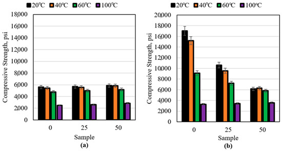
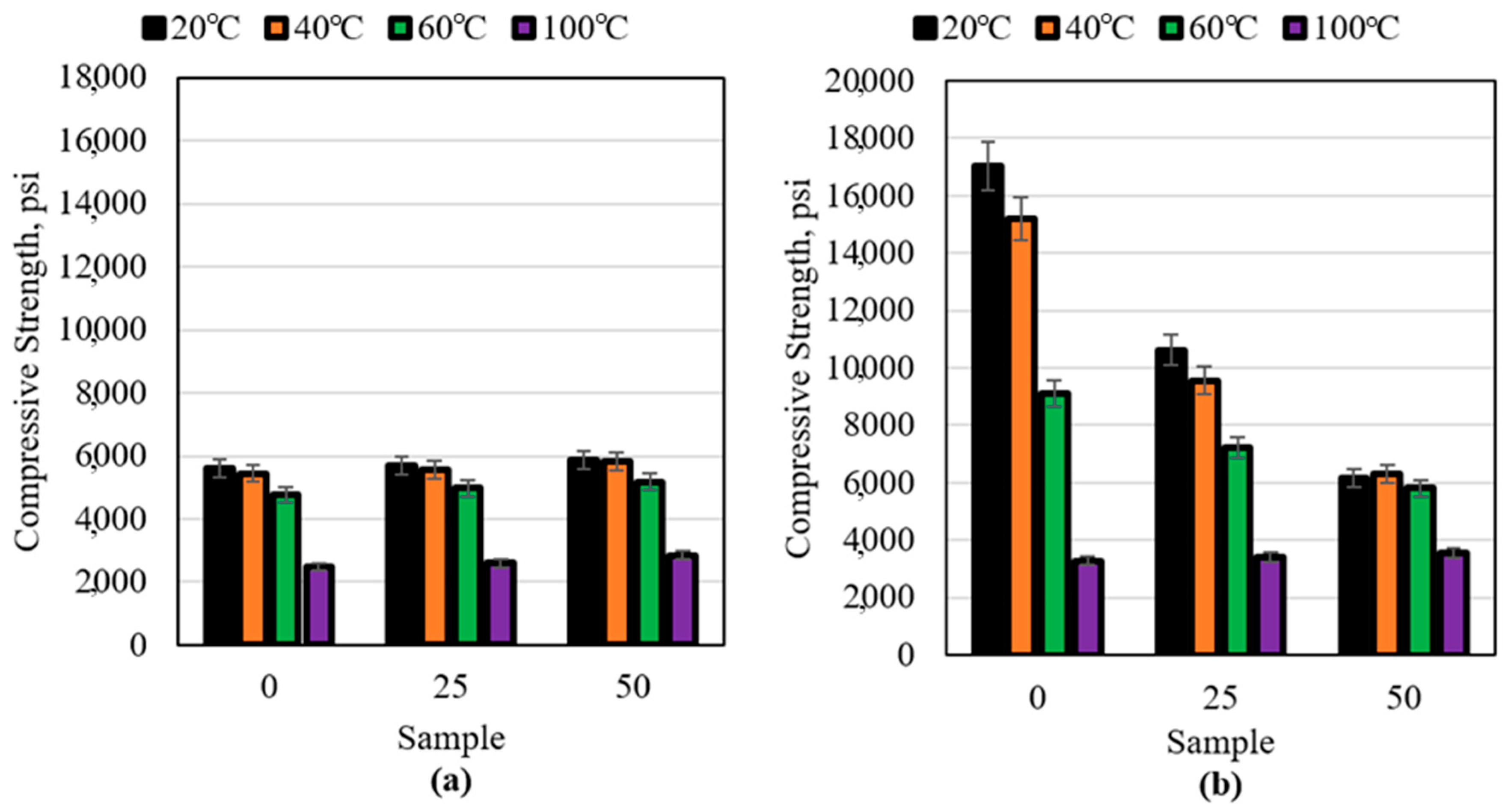
Temperature had the most pronounced influence on composite performance, shown in Figure 8. As exposure temperature increased from 20 °C to 100 °C, both deformation and failure strengths decreased progressively.
Figure 8.
(a) Failure Strength and (b) Deformation Strength of the 0, 25, and 50 wt% Fly Ash Samples Placed in 20 °C, 40 °C, 60 °C, and 100 °C Water for 10 Consecutive Days.
At 100 °C, failure strength decreased to approximately 2800 psi, representing a substantial reduction relative to baseline. Additionally, deformation strength and failure strength converged, indicating loss of elastic deformation capacity.
This behavior is consistent with thermally induced softening of the polymer matrix as temperature approaches its glass transition temperature (Tg). Above Tg, polymer chain mobility increases significantly, reducing modulus and strength.
Conventional Portland cement systems, in contrast, often gain strength when cured at elevated temperatures due to accelerated hydration. However, at very high temperatures or under thermal cycling, shrinkage-induced cracking may occur.
The composite’s temperature sensitivity therefore represents a key design limitation. Future optimization using high-Tg epoxy formulations could expand the operational envelope for high-temperature wells.
3.6. Carbon Dioxide Exposure
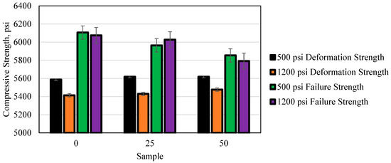
Exposure to CO2 at 60 °C under 500 psi (gaseous) and 1200 psi (supercritical) resulted in modest reductions in deformation strength but minimal change in ultimate failure strength, shown in Figure 9.
Figure 9.
Deformation and Failure Strength of the 0, 25, and 50 wt% Fly Ash Samples Placed in Gaseous and Supercritical Carbon Dioxide for 10 Consecutive Days.
In conventional cement systems, CO2 reacts with calcium hydroxide to form calcium carbonate, potentially reducing alkalinity and altering microstructure. Over extended exposure periods, carbonation may lead to permeability changes and strength variation.
The composite cement lacks reactive calcium phases, fundamentally altering its interaction with CO2. The observed reduction in deformation strength may be attributed to:
- CO2 diffusion into the polymer matrix;
- Mild plasticization effects;
- Interfacial stress redistribution under pressure.
Notably, performance under supercritical CO2 was only slightly inferior to gaseous exposure, suggesting limited phase-dependent degradation under the test duration.
Strength values remained above 5000 psi, supporting potential application in CO2 injection or storage wells, although long-term studies would be required to assess extended exposure effects.
3.7. Crude Oil Exposure (Expanded Analysis)
Exposure to heavy crude oil (450 cp) did not produce measurable reductions in deformation or failure strength across all fly ash loadings. Mechanical performance remained statistically comparable to distilled water baseline values, shown Figure 10.
Figure 10.
Deformation and Failure Strength of the 0, 25, and 50 wt% Fly Ash Samples Placed in Crude Oil for 10 Consecutive Days.
This stability can be attributed to several material characteristics:
- Hydrophobic Polymer Matrix: The epoxy matrix exhibits low affinity for non-polar hydrocarbon molecules, limiting crude oil penetration into the bulk material.
- Absence of Hydration Phases: Conventional cement contains capillary pores that may allow hydrocarbon infiltration over long exposure periods. Although hydrocarbons do not chemically degrade cement as aggressively as acids, prolonged exposure can alter wetting characteristics and permeability. The composite’s lower intrinsic permeability likely restricts such interactions.
- High Viscosity of Crude Oil: The heavy crude’s viscosity (450 cp) further limits diffusion into microstructural voids.
- Stable Polymer–Particle Interface: No evidence of debonding between fly ash particles and the resin matrix was observed during mechanical testing, suggesting that oil exposure did not compromise interfacial adhesion.
These findings indicate that the composite cement maintains mechanical integrity in hydrocarbon-rich environments and may be particularly suitable for production zones where prolonged oil contact is expected.
3.8. Acetone-Induced Degradation
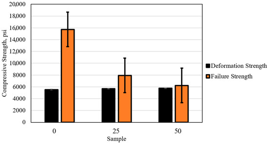
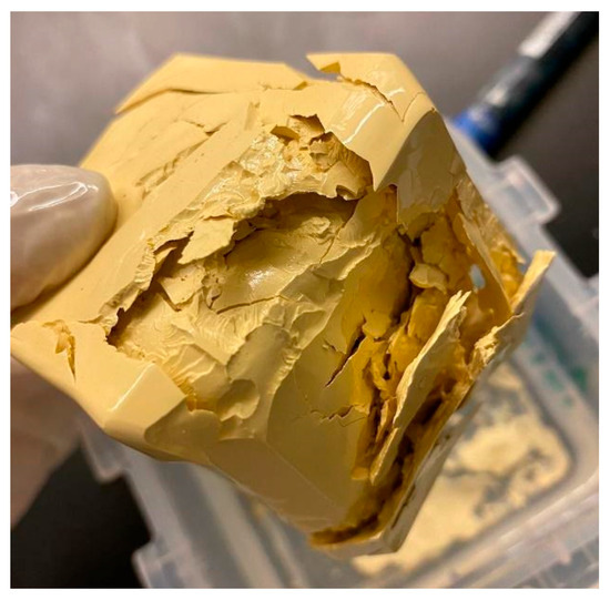
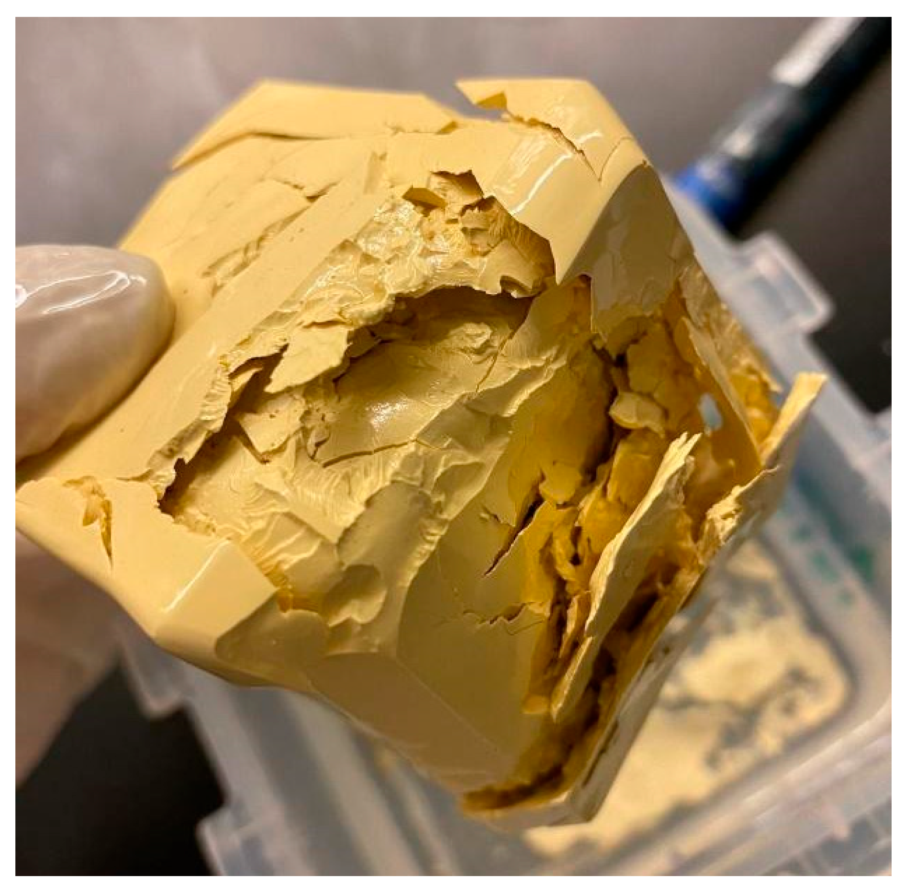
Acetone exposure resulted in progressive softening, swelling, and eventual structural degradation of the composite. Both deformation and failure strengths decreased substantially, and elastic behavior was eliminated. A sample of the cement sample subjected to acetone is presented in Figure 11.
Figure 11.
Novel Cement Sample After Placement in Acetone for 10 Consecutive Days.
This confirms that structural integrity is governed primarily by the polymer network, which is susceptible to organic solvent dissolution. Higher fly ash content slightly improved residual strength due to increased inorganic fraction.
From an operational perspective, this property introduces the possibility of controlled removal in remedial operations—a capability not available in conventional cement systems, which require mechanical milling for removal.
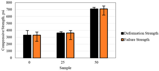
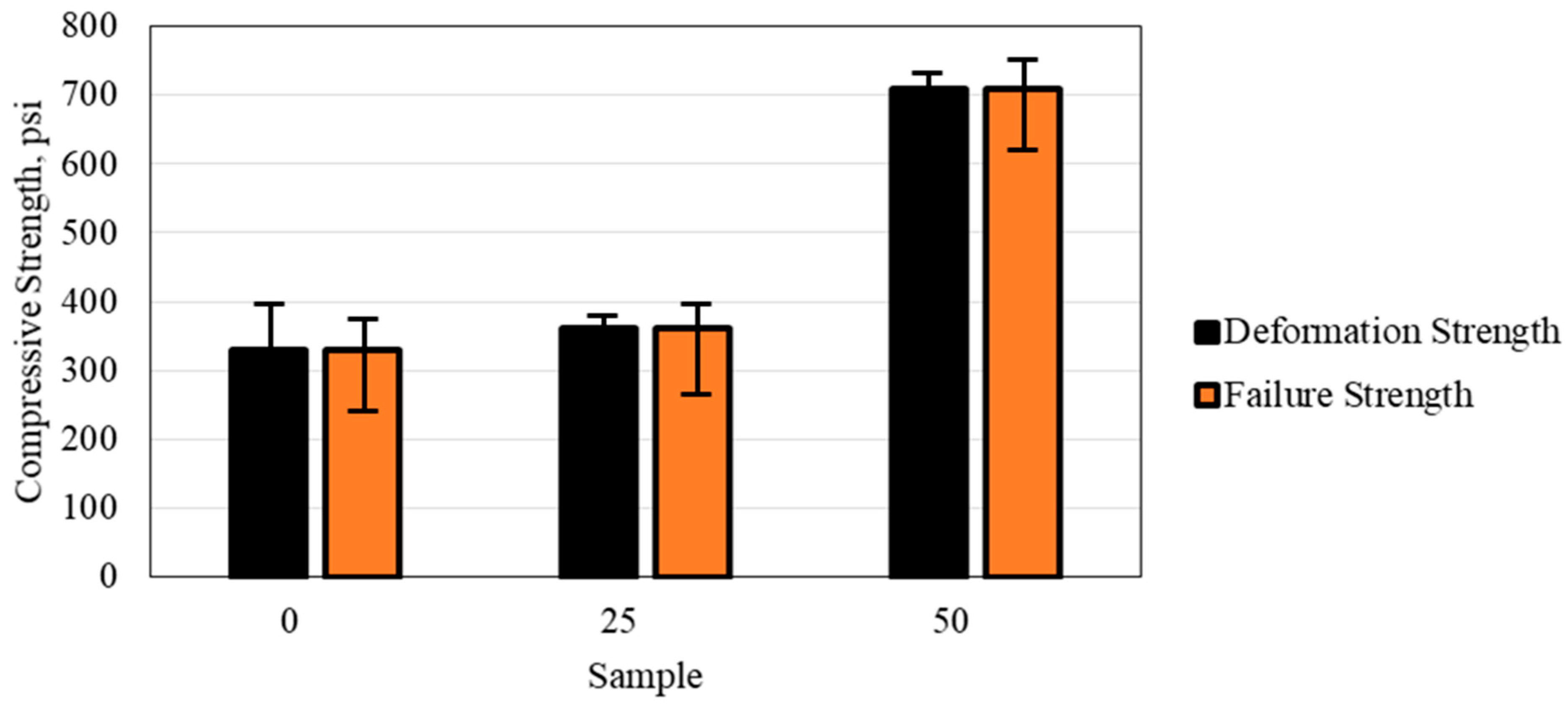
Figure 12 shows the deformation and the failure strengths of the 0, 25, and 50 wt% fly ash samples after being placed in acetone for 10 consecutive days. The first observation from the results shows that the samples lost all of their elastic properties, and therefore the deformation strength was identical to the failure strength of all three samples. The compressive strength of the samples decreased significantly compared to all other experiments due to the decomposition and weakening of the cement samples. The highest fly ash weight percent sample resulted in the highest compressive strength after being subjected to the acetone. This is an indication that the acetone had no impact on the fly ash and only worked to degrade the resin.
Figure 12.
Deformation and Failure Strength of the 0, 25, and 50 wt% Fly Ash Samples Placed in Acetone for 10 Consecutive Days.
Recent studies have highlighted the critical role of matrix densification and interfacial bonding in enhancing the durability of fly ash-based composites, particularly under aggressive environmental conditions. For instance, the incorporation of mineral additives such as limestone powder has been shown to accelerate hydration reactions, promote the formation of additional binding phases, and refine pore structure, ultimately improving resistance to chemical degradation. These findings align with the behavior observed in polymer-modified systems, where stronger interfacial adhesion between the binder and filler phases reduces permeability and limits the ingress of harmful agents such as acids. Accordingly, the improved performance of epoxy–fly ash composites can be attributed not only to the intrinsic chemical resistance of the polymer matrix but also to the enhanced microstructural integrity arising from better particle–matrix interaction [82,83].
4. Microstructural and Mechanistic Interpretation
4.1. Load Transfer Mechanism
In the composite system, compressive load is primarily carried by the continuous epoxy matrix, while fly ash particles act as rigid fillers that contribute to stiffness enhancement and stress redistribution. Under applied load, stress is transferred from the deformable polymer matrix to the stiffer mineral particles through interfacial shear stresses.
At low fly ash loading (0 wt%), the material behaves as a highly ductile polymer network. As fly ash content increases, particle–particle interactions become more significant, leading to reduced strain capacity and earlier fracture initiation. This explains the observed narrowing of the gap between deformation strength and failure strength with increasing filler content.
The relatively stable compressive strength at 50 wt% loading suggests effective interfacial bonding between fly ash particles and the epoxy matrix. Poor interfacial adhesion would have manifested as premature debonding and significant strength loss.
4.2. Chemical Resistance Mechanism
The superior acid and CO2 resistance of the composite compared to conventional Portland cement can be attributed to fundamental differences in binding chemistry.
Portland cement relies on hydration products (C–S–H gel and Ca(OH)2), which are susceptible to:
- Acid dissolution;
- Decalcification;
- Carbonation reactions.
In contrast, the composite’s structural integrity depends on a crosslinked organic polymer network. Acidic or carbonic environments do not directly dissolve this network. Instead, degradation mechanisms are diffusion-limited and primarily affect surface regions.
The relatively small reduction in deformation strength under acidic and CO2 exposure suggests localized polymer softening rather than bulk structural compromise. Fly ash particles, composed largely of aluminosilicate phases, remain chemically stable under these conditions and contribute to mechanical reinforcement.
4.3. Fluid Transport and Porosity Considerations
Minor brine expulsion observed during high salinity testing indicates the presence of isolated micro voids. These may originate from:
- Air entrapment during mixing;
- Incomplete wetting of filler surfaces;
- Particle packing heterogeneity.
However, because compressive strength remained stable, these voids likely form a non-percolating pore structure.
Conventional cement systems typically exhibit interconnected capillary porosity, which facilitates fluid transport, salt crystallization, and chemical attack. The polymer matrix in the composite likely significantly reduces effective permeability, thereby limiting fluid diffusion and enhancing durability.
Future work including permeability testing and microstructural imaging (e.g., SEM or micro-CT) would further quantify this effect.
4.4. Thermal Softening Behavior
The strength reduction at 100 °C is consistent with polymer thermomechanical behavior. As temperature approaches the epoxy glass transition temperature (Tg), molecular mobility increases, reducing stiffness and compressive strength.
Unlike cement hydration systems, which may gain strength with elevated curing temperature, polymer-based composites are constrained by thermal softening thresholds. Therefore, the composite’s operational temperature window is governed by resin formulation.
Selection of high-Tg epoxy systems could significantly improve high-temperature performance without altering composite architecture.
5. Engineering Applicability and Operational Envelope
While laboratory-scale mechanical testing provides insight into material durability, translation to field deployment requires evaluation within an operational framework. Based on the experimental findings, the fly ash–epoxy composite cement demonstrates distinct performance characteristics that define its potential application envelope.
5.1. Suitable Downhole Environments
The composite exhibited strong resistance to:
- High acid concentrations (up to 28 wt% HCl);
- High salinity brines (up to 20 wt% NaCl);
- Alkaline environments (up to 28 wt% NaOH);
- Carbon dioxide exposure (gaseous and supercritical);
- Direct crude oil contact.
These characteristics suggest suitability for:
- Acidizing-prone wells;
- Carbon capture and storage (CCS) injection wells;
- CO2 enhanced oil recovery (EOR) operations;
- High-salinity formation environments;
- Production zones with prolonged hydrocarbon exposure.
Conventional Portland cement systems often require specialized additives to achieve comparable acid or CO2 resistance. The composite achieves this without reliance on hydration chemistry, reducing susceptibility to calcium leaching and carbonation degradation.
5.2. Temperature Limitations
Thermal exposure results indicate that compressive strength declines significantly at 100 °C due to polymer softening. Therefore, the current formulation is best suited for:
- Low- to moderate-temperature wells (<90–100 °C)
For high-temperature reservoirs, material optimization through high-glass-transition epoxy systems would be necessary. This highlights that the composite is not a universal replacement for Class G cement, but rather a specialized alternative for chemically aggressive, moderate-temperature environments.
5.3. Mechanical Behavior Compared to Conventional Cement
One of the most significant differences between the composite and conventional oilwell cement lies in deformation behavior.
Portland cement is inherently brittle, failing abruptly once peak compressive stress is reached. In contrast, the composite demonstrated measurable elastic deformation prior to failure. This semi-ductile response may:
- Improve resistance to microannulus formation;
- Enhance tolerance to casing expansion/contraction;
- Reduce crack propagation under cyclic loading.
Such characteristics may be particularly beneficial in injection wells experiencing pressure cycling.
5.4. Sustainability and Material Efficiency
The fly ash–epoxy composite cement system represents a strategic integration of industrial by-products into advanced polymer matrices, with significant implications for sustainability and resource efficiency. By incorporating up to 50 wt% Class F fly ash into the polymer network, this composite simultaneously addresses material cost, mechanical performance, and environmental stewardship [67,77,85]. Partial replacement of epoxy with fly ash reduces the demand for virgin polymer, which carries high embodied energy, while maintaining structural integrity in aggressive downhole environments [7,88]. This approach aligns with circular economy principles by diverting significant quantities of fly ash from landfills and repurposing them as functional construction material [85,88].
From an environmental perspective, conventional Portland cement production is a major source of CO2 emissions, energy consumption, and natural resource depletion. In contrast, the composite system leverages the pozzolanic and filler properties of fly ash, which contribute to reduced CO2 intensity and lower lifecycle energy demands per unit of material applied [77,84,88]. Research on fly ash-based geopolymers and polymer-fly ash composites has demonstrated that incorporating up to 50% fly ash can lower CO2 emissions by 20–40% relative to conventional Class G cement while simultaneously improving resistance to acid, CO2, and high-salinity exposure [67,77,84,86,88]. These enhancements extend service life and reduce the likelihood of frequent remedial operations, further decreasing the long-term environmental footprint of well completion and maintenance activities [86,88].
Economically, the use of fly ash significantly lowers raw material cost due to its availability as an industrial by-product, without compromising mechanical performance [67,85]. The semi-ductile behavior of the composite enhances its ability to accommodate casing deformation and cyclic loading, potentially preventing microannulus formation and associated production losses. This mechanical resilience may translate into fewer workovers and lower operational expenditures over the well’s life [86,88]. Additionally, partial polymer replacement with fly ash reduces overall polymer consumption, which has both cost and sustainability benefits, as polymer production is energy-intensive [7].
Table 1 provides a comparative overview of economic and sustainability-related performance metrics for the fly ash–epoxy composite versus conventional Class G cement, integrating both literature-based estimates and material property considerations.
Table 1.
Comparative Economic and Sustainability Metrics for Fly Ash Epoxy Composite and Class G Cement.
5.5. Remedial Potential
The acetone degradation experiments demonstrated that the composite can be chemically weakened if necessary. Although acetone is not naturally present in reservoirs, this property introduces a potential advantage in controlled remedial scenarios where partial removal of cement is required.
Conventional cement systems typically require mechanical milling for removal, which can be operationally complex and costly.
5.6. Cost–Benefit Analysis
From an operational perspective, Class G cement remains the simplest to deploy, with low placement complexity and predictable curing behavior; however, this simplicity comes at the cost of higher failure risk, particularly in aggressive environments such as CO2 or acidic conditions, which can lead to significant remediation expenses and only moderate long-term well integrity. In contrast, epoxy-based systems introduce slightly more complexity during placement, especially at higher fly ash loadings, but offer clear advantages in performance. The epoxy with 25 wt% fly ash system strikes a balance, providing faster curing, reduced failure risk, and improved well integrity with relatively low remediation needs. Increasing the fly ash content to 50 wt% further enhances durability and significantly lowers both failure risk and remediation costs, ultimately delivering very high well lifetime integrity, albeit with moderately more complex handling and curing behavior. This is summarized in Table 2.
Table 2.
Operational Cost-Benefit Analysis of the Epoxy Resin Cement vs. Portland Cement Class G.
6. Conclusions
This study demonstrates that a fly ash–epoxy composite cement can maintain mechanical integrity under a wide range of chemically aggressive downhole conditions, including acidic, alkaline, high-salinity, and carbon dioxide (CO2)-rich environments. The material consistently retained compressive strength above 5000 psi under most conditions, with degradation primarily affecting elastic deformation rather than ultimate strength. Unlike conventional Portland cement systems, the composite showed strong resistance to acid attack and carbonation, as well as stability in crude oil environments, highlighting the advantages of its polymer-based matrix. However, thermal exposure at 100 °C significantly reduced strength due to polymer softening, defining the primary operational limitation of the system. The composite also exhibited a semi-ductile response, which may improve resistance to microannulus formation and cyclic loading. Overall, the incorporation of up to 50 wt% fly ash provides a chemically resilient and mechanically adaptable alternative cement system for moderate-temperature wells in aggressive environments. Future work should focus on long-term durability, permeability characterization, and performance under cyclic loading to further establish field applicability.
Funding
Funding for this work was provided by The American University in Cairo through their Faculty Support Grant.
Institutional Review Board Statement
Not Applicable.
Informed Consent Statement
Not Applicable.
Data Availability Statement
The datasets used and/or analyzed during the current study are available from the corresponding author on reasonable request due to privacy.
Acknowledgments
The authors wish to thank The American University in Cairo for funding this research through their Faculty Support Grant.
Conflicts of Interest
The author declares no conflicts of interest.
References
- Al-Yami, A. An Overview of Different Chemicals Used in Designing Cement Slurries for Oil and Gas Wells. In Proceedings of the 2015 Kuwait Oil & Gas Show Conference, Mishref, Kuwait, 11–14 October 2015. paper SPE 175259. [Google Scholar]
- Brattekås, B.; Steinsbø, M.; Graue, A.; Fernø, M.A.; Espedal, H.; Seright, R.S. New Insight Into Wormhole Formation in Polymer Gel During Water Chase Floods With Positron Emission Tomography. SPE J. 2017, 22, 32–40. [Google Scholar] [CrossRef] [Scilit]
- Cha, M.; Alqahtani, N.B.; Yao, B.; Yin, X.; Kneafsey, T.J.; Wang, L.; Wu, Y.-S.; Miskimins, J.L. Cryogenic Fracturing of Wellbores Under True Triaxial-Confining Stresses: Experimental Investigation. SPE J. 2018, 23, 1271–1289. [Google Scholar] [CrossRef] [Scilit]
- Dande, S.; Stewart, R.R.; Dyaur, N. Effect of Fluids on the Elastic Properties of 3D-Printed Anisotropic Rock Models. Petrophysics 2021, 62, 537–552. [Google Scholar] [CrossRef] [Scilit]
- Ding, L.; Chen, W.; Han, C.; Geng, H.; Zhang, Q. Research on a Typical Casing Failure during Drilling of Cement Plugs in Ultradeep Wells. SPE J. 2023, 28, 2753–2766. [Google Scholar] [CrossRef] [Scilit]
- Fakher, S.; Fakher, A. Investigating the Use of CO2 as a Hydraulic Fracturing Fluid for Water Sustainability and Environmental Friendliness. In Proceedings of the SPE/IATMI Asia Pacific Oil & Gas Conference and Exhibition, Virtual, 12–14 October 2021. [Google Scholar] [CrossRef] [Scilit]
- Fakher, S.; Khlaifat, A. Experimental Investigation of Polymer Injection in High Permeability Conduits for Material Sustainability and Behavior in Oil Reservoirs. Polymers 2023, 15, 2950. [Google Scholar] [CrossRef] [Scilit]
- Fakher, S.; El-Tonbary, A.; Abdelaal, H.; Elgahawy, Y.; Imqam, A. Carbon Dioxide Sequestration in Unconventional Shale Reservoirs Via Physical Adsorption: An Experimental Investigation. In Proceedings of the SPE Europec, Virtual, 1–3 December 2020. [Google Scholar] [CrossRef] [Scilit]
- Hassan, A.; Chandra, V.; Yutkin, M.P.; Patzek, T.W.; Espinoza, D.N. Imaging and Characterization of Microporous Carbonates Using Confocal and Electron Microscopy of Epoxy Pore Casts. SPE J. 2019, 24, 1220–1233. [Google Scholar] [CrossRef] [Scilit]
- Helgaker, J.F.; Ijzermans, S.; Landheim, T.J.; Eeg, T.B.; Hverven, S.M.; Piotrowski, P. Large-Scale Erosion Testing of an Unbonded Flexible Pipe. SPE J. 2017, 22, 736–745. [Google Scholar] [CrossRef] [Scilit]
- Hrovat, M.; Patz, S.; Rossini, D.; Schwartz, L.M.; Straley, C.; Stromski, M.E. Particle Filtration In Sandstone Cores: A Novel Application Of Chemical Shift Magnetic Resonance Imaging Techniques. Log Anal. 1995, 36, SPWLA-1995-v36n2a3. [Google Scholar]
- Ikem, V.O.; Menner, A.; Bismarck, A.; Norman, L.R. Screen: A Novel Method To Produce an In-Situ Gravel Pack. SPE J. 2014, 19, 437–442. [Google Scholar] [CrossRef] [Scilit]
- Jeffrey, G.; Bunger, A. A Detailed Comparison of Experimental and Numerical Data on Hydraulic Fracture Height Growth Through Stress Contrasts. SPE J. 2009, 14, 413–422. [Google Scholar] [CrossRef] [Scilit]
- Medlin, L.; Massé, L. Laboratory Experiments in Fracture Propagation. SPE J. 1984, 24, 256–268. [Google Scholar] [CrossRef] [Scilit]
- Mohanty, K.K.; Tong, S.; Miller, C.; Zeng, T.; Honarpour, M.M.; Turek, E.; Peck, D.D. Improved Hydrocarbon Recovery Using Mixtures of Energizing Chemicals in Unconventional Reservoirs. SPE Reserv. Eval. Eng. 2019, 22, 1436–1448. [Google Scholar] [CrossRef] [Scilit]
- Nguyen, P.D.; Dewprashad, B.T.; Weaver, J.D. New Approach for Enhancing Fracture Conductivity. SPE Prod. Facil. 2000, 15, 83–89. [Google Scholar] [CrossRef] [Scilit]
- Pourciau, R.D.; Fisk, J.H.; Descant, F.J.; Waltman, R.B. Completion and Well-Performance Results, Genesis Field, Deepwater Gulf of Mexico. SPE Drill. Complet. 2005, 20, 147–155. [Google Scholar] [CrossRef] [Scilit]
- Todd, L.; Cleveland, M.; Docherty, K.; Reid, J.; Cowan, K.; Yohe, C. Big problem-small solution: Nanotechnology-based sealing fuid. In Proceedings of the SPE Annual Technical Conference and Exhibition, Dallas, TX, USA, 24–26 September 2018. [Google Scholar] [CrossRef] [Scilit]
- Tran, S.; Habibi, A.; Dehghanpour, H.; Hazelton, M.; Rose, J. Leakoff and Flowback Experiments on Tight Carbonate Core Plugs. SPE Drill. Complet. 2021, 36, 150–163. [Google Scholar] [CrossRef] [Scilit]
- Wu, W.; Sharma, M. Acid Fracturing in Shales: Effect of Dilute Acid on Properties and Pore Structure of Shale. SPE Prod. Oper. 2017, 32, 51–63. [Google Scholar] [CrossRef] [Scilit]
- Fakher, S.; Elgahawy, Y.; Abdelaal, H.; Imqam, A. What are the Dominant Flow Regimes During Carbon Dioxide Propagation in Shale Reservoirs’ Matrix, Natural Fractures and Hydraulic Fractures? In Proceedings of the SPE Western Regional Meeting, Virtual, 20–22 April 2021. [Google Scholar] [CrossRef] [Scilit]
- Fakher, S.; Khlaifat, A.; Nameer, H. Improving electric submersible pumps efficiency and mean time between failure using permanent magnet motor. Upstream Oil Gas Technol. 2022, 9, 100074. [Google Scholar] [CrossRef] [Scilit]
- Fakher, S. Development of novel mathematical models for laboratory studies of hydrolyzed polyacrylamide polymer injectivity in high-permeability conduits. J. Pet. Explor. Prod. Technol. 2020, 10, 2035–2043. [Google Scholar] [CrossRef] [Scilit]
- Fakher, S.; Imqam, A. A simplified method for experimentally quantifying crude oil swelling during immiscible carbon dioxide injection. J. Pet. Explor. Prod. Technol. 2020, 10, 3031–3042. [Google Scholar] [CrossRef] [Scilit]
- Fakher, S.; Imqam, A. Flow of carbon dioxide in micro and nano pores and its interaction with crude oil to induce asphaltene instability. SN Appl. Sci. 2020, 2, 1039. [Google Scholar] [CrossRef] [Scilit]
- Bensted, J. Retardation of Cement Slurries to 250ºF. In Proceedings of the 1991 SPE Offshore Europe, Aberdeen, UK, 3–6 September 1991. paper SPE 23073. [Google Scholar]
- Adewunmi, A.A.; Ismail, S.; Owolabi, T.O.; Sultan, A.S.; Olatunji, S.O.; Ahmad, Z. Modeling the thermal behavior of coal fly ash based polymer gel system for water reduction in oil and gas wells. J. Pet. Sci. Eng. 2017, 157, 430–440. [Google Scholar] [CrossRef] [Scilit]
- Brothers, L.; Chatterji, J.; Childs, J.; Vinson, E. Synthetic Retarder for High-Strength Cements. In Proceedings of the 1991 SPE/IADC Drilling Conference, Amsterdam, The Netherlands, 11–14 March 1991. paper SPE 21976. [Google Scholar]
- Carpenter, C. Microchannel Remediation of a Cement Packer Unlocks Mature-Field Potential. J. Pet. Technol. 2019, 71, 56–57. [Google Scholar] [CrossRef] [Scilit]
- Forbes, D.; Uswak, G. Detection of Gas Migration Behind Casing Using Ultrasonic Imaging Methods. J. Can. Pet. Technol. 1992, 31. [Google Scholar] [CrossRef] [Scilit]
- Goodwin, K.; Crook, R. Cement Sheath Stress Failure. SPE Drill. Eng. 1992, 7, 291–296. [Google Scholar] [CrossRef] [Scilit]
- Hart, W.; Smith, T. Improved Cementing Practices Reduce Cementing Failures. J. Can. Pet. Technol. 1990. [Google Scholar] [CrossRef] [Scilit]
- Iremonger, S.S.; Cheung, B.; Carey, J. Direct Strain Mapping of a Cement Sheath; A New Tool for Understanding and Preventing Cement Failure in Thermal Wells. In Proceedings of the SPE Thermal Well Integrity and Design Symposium, Banff, AB, Canada, 28–30 November 2017. [Google Scholar] [CrossRef] [Scilit]
- Kalil, I.A.; McSpadden, A.R. Casing Burst Stresses in Particulate-Filled Annuli: Where Is the Cement? SPE Drill. Complet. 2012, 27, 473–485. [Google Scholar] [CrossRef] [Scilit]
- Meng, M.; Frash, L.; Carey, J.W.; Niu, Z.; Zhang, W.; Guy, N.; Lei, Z.; Li, W.; Welch, N. Predicting Cement-Sheath Integrity with Consideration of Initial State of Stress and Thermoporoelastic Effects. SPE J. 2021, 26, 3505–3528. [Google Scholar] [CrossRef] [Scilit]
- Nguyen, P.D.; Brumley, J.L.; Dewprashad, B.T.; Dusterhoft, R.G.; Weaver, J.D. Stabilizing Wellbores in Unconsolidated Formations for Fracture Stimulation. SPE Prod. Facil. 2000, 15, 262–269. [Google Scholar] [CrossRef] [Scilit]
- Nguyen, P.D.; Weaver, J.D.; Rickman, R.D.; Sanders, M.W. Application of Diluted Consolidation Systems To Improve Effectiveness of Proppant Flowback Remediation—Laboratory and Field Results. SPE Prod. Oper. 2009, 24, 50–59. [Google Scholar] [CrossRef] [Scilit]
- Pollock, R.; Beecroft, W.; Carter, L. Cementing Practices for Thermal Wells. J. Can. Pet. Technol. 1966, 5, 130–134. [Google Scholar] [CrossRef] [Scilit]
- Shadravan, A.; Schubert, J.; Amani, M.; Teodoriu, C. Using Fatigue-Failure Envelope for Cement-Sheath-Integrity Evaluation. SPE Drill. Complet. 2015, 30, 68–75. [Google Scholar] [CrossRef] [Scilit]
- Shryock, S.H.; Slagle, K.A. Problems related to squeeze cementing. J. Pet. Technol. 1968, 20, 801–807. [Google Scholar] [CrossRef] [Scilit]
- Stair, C.D.; Hinnant, C.H.; Hines, N.O.; Schober, J.M.; Davis, C.L.; Lizak, K.F.; Pugh, B.A. Planning and Execution of Highly Overbalanced Completions From a Floating Rig: The Ursa-Princess Waterflood Project. SPE Drill. Complet. 2011, 26, 396–407. [Google Scholar] [CrossRef] [Scilit]
- Teufel, L.W.; Clark, J.A. Hydraulic Fracture Propagation in Layered Rock: Experimental Studies of Fracture Containment. Soc. Pet. Eng. J. 1984, 24, 19–32. [Google Scholar] [CrossRef] [Scilit]
- Thiercelin, M.J.; Dargaud, B.; Baret, J.F.; Rodriquez, W.J. Cement Design Based on Cement Mechanical Response. SPE Drill. Complet. 1998, 13, 266–273. [Google Scholar] [CrossRef] [Scilit]
- Wang, Q.; Qiao, L.; Song, P. Effect of Fly Ash and Slag on the Resistance to H2S Attack of Oil Well Cement. Adv. Mater. Res. 2009, 79–82, 71–74. [Google Scholar] [CrossRef] [Scilit]
- Webb, P.J.C.; Nistad, T.A.; Knapstad, B.; Ravenscroft, P.D.; Collins, I.R. Advantages of a New Chemical Delivery System for Fractured and Gravel- Packed Wells. SPE Prod. Facil. 1999, 14, 210–218. [Google Scholar] [CrossRef] [Scilit]
- Yao, C.; Liu, B.-S.; Liu, Y.-Q.; Zhao, J.; Lei, Z.-D.; Wang, Z.; Cheng, T.-X.; Li, L. Quantitative Investigation on Natural Gas Flooding Characteristics in Tight Oil Cores after Fracturing Based on Nuclear Magnetic Resonance Technique. SPE J. 2022, 27, 3757–3772. [Google Scholar] [CrossRef] [Scilit]
- Zhang, L.; Zhou, F.; Mou, J.; Feng, W.; Li, Z.; Zhang, S. An Integrated Experimental Method to Investigate Tool-Less Temporary-Plugging Multistage Acid Fracturing of Horizontal Well by Using Self-Degradable Diverters. SPE J. 2020, 25, 1204–1219. [Google Scholar] [CrossRef] [Scilit]
- Copeland, C.; McAuley, J. Controlling Sand With an Epoxy-Coated, High-Solids-Content Gravel Slurry. J. Pet. Technol. 1974, 26, 1215–1220. [Google Scholar] [CrossRef] [Scilit]
- Du, J.; Bu, Y.; Liu, H.; Shen, Z. Experimental Feasibility Study of a Novel Organic-Inorganic Hybrid Material for Offshore Oil Well Cementation. In Proceedings of the 28th International Ocean and Polar Engineering Conference, Sapporo, Japan, 10–15 June 2018. [Google Scholar]
- Huo, J.; Peng, Z.-G.; Xu, K.; Feng, Q.; Xu, D.-Y. Novel micro-encapsulated phase change materials with low melting point slurry: Characterization and cementing application. Energy 2019, 186, 115920. [Google Scholar] [CrossRef] [Scilit]
- Kosek, J.R.; DuPont, J.N.; Marder, A.R. Effect of Porosity on Resistance of Epoxy Coatings to Cold-Wall Blistering. Corrosion 1995, 51, 861–871. [Google Scholar] [CrossRef] [Scilit]
- Leggat, R.; Zhang, W.; Buchheit, R.; Taylor, S. Performance of Hydrotalcite Conversion Treatments on AA2024-T3 When Used in a Coating System. Corrosion 2002, 58, 322–328. [Google Scholar] [CrossRef] [Scilit]
- Leggett, S.; Reid, T.; Zhu, D.; Hill, A.D. Experimental Investigation of Low-Frequency Distributed Acoustic Strain-Rate Responses to Propagating Fractures. SPE J. 2022, 27, 3814–3828. [Google Scholar] [CrossRef] [Scilit]
- Liu, B.; Li, Y.; Lin, H.; Cao, C.-N. Electrochemical Impedance Spectroscopy Study on the Diffusion Behavior of Water through Epoxy Coatings. Corrosion 2003, 59, 817–820. [Google Scholar] [CrossRef] [Scilit]
- Mansfeld, F. Discussion: Effectiveness of Ion Vapor-Deposited Aluminum as a Primer for Epoxy and Urethane Topcoats. Corrosion 1994, 50, 609–610. [Google Scholar] [CrossRef] [Scilit]
- Norman, L.R.; Terracina, J.M.; McCabe, M.A.; Nguyen, P.D. Application of Curable Resin-Coated Proppants. SPE Prod. Eng. 1992, 7, 343–349. [Google Scholar] [CrossRef] [Scilit]
- Haydar, R.R.; Fakher, S. Development of a Low Cost Environmentally Friendly Proppant with High Buoyancy for Hydraulic Fracturing Operations. In Proceedings of the 57th U.S. Rock Mechanics/Geomechanics Symposium, Atlanta, GA, USA, 25–28 June 2023. [Google Scholar] [CrossRef] [Scilit]
- Sanabria, A.E.; Knudsen, K.; Leon, G.A. Thermal activated resin to repair casing leaks in the middle east. Abu Dhabi International Petroleum Exhibition & Conference, Abu Dhabi, United Arab Emirates, 7–10 November 2016. [Google Scholar] [CrossRef] [Scilit]
- Shao, Y.; Li, Y.; Du, Y.; Wang, F. Enhancement of the Protectiveness of Epoxy Coatings with Surface-Modified Nano-Titanium Particles. Corrosion 2006, 62, 483–490. [Google Scholar] [CrossRef] [Scilit]
- Shaughnessy, C.M.; Salathiel, W.M.; Penberthy, W.L. A New, Low-Viscosity, Epoxy Sand-Consolidation Process. J. Pet. Technol. 1978, 30, 1805–1812. [Google Scholar] [CrossRef] [Scilit]
- Singh, D.; Ghosh, R. Unexpected Deterioration of Fusion-Bonded Epoxy-Coated Rebars Embedded in Chloride- Contaminated Concrete Environments. Corrosion 2005, 61, 815–829. [Google Scholar] [CrossRef] [Scilit]
- Spinks, G.M.; Dominis, A.J.; Wallace, G.G. Comparison of Emeraldine Salt, Emeraldine Base, and Epoxy Coatings for Corrosion Protection of Steel During Immersion in a Saline Solution. Corrosion 2003, 59, 22–31. [Google Scholar] [CrossRef] [Scilit]
- Sun, L.; Li, D.; Pu, W.; Li, L.; Bai, B.; Han, Q.; Zhang, Y.; Tang, X. Combining Preformed Particle Gel and Curable Resin-Coated Particles To Control Water Production from High-Temperature and High-Salinity Fractured Producers. SPE J. 2020, 25, 938–950. [Google Scholar] [CrossRef] [Scilit]
- Vicente Perez, M.; Melo, J.; Blanc, R.; Roncete, A.; Jones, P. Epoxy resin helps restore well integrity in ofshore well: Case history. In Proceedings of the OTC Brasil Rio de Janeiro, Rio de Janeiro, Brazil, 24–26 October 2017. [Google Scholar] [CrossRef] [Scilit]
- Wasnik, A.S.; Mete, S.V.; Ghosh, B. Application of resin system for sand consolidation, mud loss control & channel repairing. In Proceedings of the SPE International Thermal Operations and Heavy Oil Symposium, Calgary, AB, Canada, 1–3 November 2005. [Google Scholar] [CrossRef]
- Zhao, Z.; Sun, J.; Liu, F.; Bai, Y.; Wang, R.; Geng, Y.; Li, Y.; Liu, C. High-Temperature-Resistant Thermal Shape Memory Polymers as Lost Circulation Materials for Fracture Formations. SPE J. 2023, 28, 2629–2641. [Google Scholar] [CrossRef] [Scilit]
- Khalifeh, M.; Saasen, A.; Vralstad, T.; Hodne, H. Potential utilization of class C fly ash-based geopolymer in oil well cementing operations. Cem. Concr. Compos. 2014, 53, 10–17. [Google Scholar] [CrossRef] [Scilit]
- Khalifeh, M.; Saasen, A.; Vralstad, T.; Hodne, H. Potential Utilization of Geopolymers in Plug and Abandonment Operations. In Proceedings of the SPE Bergen One Day Seminar, Bergen, Norway, 2 April 2014. [Google Scholar] [CrossRef] [Scilit]
- Khalifeh, M.; Hodne, H.; Korsnes, R.I.; Saasen, A. Cap Rock Restoration in Plug and Abandonment Operations; Possible Utilization of Rock-based Geopolymers for Permanent Zonal Isolation and Well Plugging. In Proceedings of the International Petroleum Technology Conference, Doha, Qatar, 6–9 December 2015. [Google Scholar] [CrossRef] [Scilit]
- Khalifeh, M.; Hodne, H.; Saasen, A.; Integrity, O.; Eduok, E.I. Usability of Geopolymers for Oil Well Cementing Applications: Reaction Mechanisms, Pumpability, and Properties. In Proceedings of the SPE Asia Pacific Oil & Gas Conference and Exhibition, Perth, Australia, 25–27 October 2016. [Google Scholar] [CrossRef] [Scilit]
- Liu, H.; Sanjayan, J.G.; Bu, Y. The application of sodium hydroxide and anhydrous borax as composite activator of class F fly ash for extending setting time. Fuel 2017, 206, 534–540. [Google Scholar] [CrossRef] [Scilit]
- Liu, X.; Ramos, M.J.; Nair, S.D.; Lee, H.; Espinoza, D.N.; van Oort, E. True Self-Healing Geopolymer Cements for Improved Zonal Isolation and Well Abandonment. In Proceedings of the SPE/IADC Drilling Conference and Exhibition, The Hague, The Netherlands, 14–16 March 2017. [Google Scholar] [CrossRef] [Scilit]
- Olvera, R.; Panchmatia, P.; Juenger, M.; Aldin, M.; van Oort, E. Long-term Oil Well Zonal Isolation Control Using Geopolymers: An Analysis of Shrinkage Behavior. Paper presented at the SPE/IADC International Drilling Conference and Exhibition, The Hague, The Netherlands, 5–7 March 2019. [Google Scholar] [CrossRef] [Scilit]
- van Oort, E.; Juenger, M.; Liu, X.; McDonald, M. Silicate-Activated Geopolymer Alternatives to Portland Cement for Thermal Well Integrity. In Proceedings of the SPE Thermal Well Integrity and Design Symposium, Banff, AB, Canada, 19–21 November 2019. [Google Scholar] [CrossRef] [Scilit]
- Reinsch, T.; Kranz, S.; Saadat, A.; Huenges, E.; Rinke, M.; Brandt, W.; Schulz, P. Balanced Reverse-Cleanout Operation: Removing Large and Heavy Particles From a Geothermal Well. SPE Prod. Oper. 2017, 32, 228–237. [Google Scholar] [CrossRef] [Scilit]
- Ridha, S.; Yerikania, U. New Nano-Geopolymer Cement System Improves Wellbore Integrity Upon Acidizing Job: Experimental Findings. In Proceedings of the SPE/IATMI Asia Pacific Oil & Gas Conference and Exhibition, Nusa Dua, Bali, Indonesia, 20–22 October 2015. [Google Scholar] [CrossRef] [Scilit]
- Salehi, S.; Khattak, M.J.; Rizvi, H.; Karbalaei, S.F.; Kiran, R. Sensitivity analysis of fly ash geopolymer cement slurries: Implications for oil and gas wells cementing applications. J. Nat. Gas Sci. Eng. 2017, 37, 116–125. [Google Scholar] [CrossRef] [Scilit]
- Salehi, S.; Ali, N.; Khattak, M.J.; Rizvi, H. Geopolymer Composites as Efficient and Economical Plugging Materials in Peanuts Price Oil Market. In Proceedings of the SPE Annual Technical Conference and Exhibition, Dubai, United Arab Emirates, 26–28 September 2016. [Google Scholar] [CrossRef] [Scilit]
- Sugumaran, M. Study on Effect of Low Calcium Fly Ash on Geopolymer Cement for Oil Well Cementing. In Proceedings of the SPE/IATMI Asia Pacific Oil & Gas Conference and Exhibition, Nusa Dua, Bali, Indonesia, 20–22 October 2015. [Google Scholar] [CrossRef] [Scilit]
- Suppiah, R.R.; Rahman, S.H.A.; Irawan, S.; Shafiq, N. Development of New Formulation of Geopolymer Cement for Oil Well Cementing. In Proceedings of the International Petroleum Technology Conference, Bangkok, Thailand, 14–16 November 2016. [Google Scholar] [CrossRef] [Scilit]
- Wang, H.; Ouyang, S.; Lv, Y.; Chen, S.; Zhai, Z.; Wang, D.; Jin, W. Mechanical properties and microstructural mechanism of ternary geopolymer cementitious materials based on molybdenum tailings, red mud and GGBS. Constr. Build. Mater. 2026, 520, 145938. [Google Scholar] [CrossRef] [Scilit]
- Lv, Y.; Chen, Y.; Dai, W.; Yang, H.; Jiang, L.; Li, K.; Jin, W. Preparation and Properties of Porous Concrete Based on Geopolymer of Red Mud and Yellow River Sediment. Materials 2024, 17, 923. [Google Scholar] [CrossRef] [Scilit]
- Chen, Q.; Jin, W.; Li, J.; Huang, M.; Fang, P. Influence of Limestone Powder as Activator on the Enhancement of Early Mechanical Strength and Durability of High Blending Fly Ash Mortar Cured Under Different Temperatures. Materials 2025, 18, 5087. [Google Scholar] [CrossRef] [Scilit]
- Wang, L.; Guo, F.; Lin, Y.; Yang, H.; Tang, S.W. Comparison between the effects of phosphorous slag and fly ash on the C–S–H structure, long-term hydration heat and volume deformation of cement-based materials. Constr. Build. Mater. 2020, 250, 118807. [Google Scholar] [CrossRef] [Scilit]
- Li, Z.; Wu, Z.; Tang, S.; Wan, C.; Fan, Y.; Xue, Y.; Cheng, L.; Li, Z. Study on preparation and properties of core-shell type non-sintered aggregate from municipal solid waste incineration fly ash. Constr. Build. Mater. 2026, 515, 145640. [Google Scholar] [CrossRef] [Scilit]
- Wang, L.; Jin, M.; Guo, F.; Wang, Y.; Tang, S. Pore structural and fractal analysis of the influence of fly ash and silica fume on the mechanical property and abrasion resistance of concrete. Fractals 2021, 29, 2140003. [Google Scholar] [CrossRef] [Scilit]
- Wang, L.; Jin, M.; Guo, F.; Wang, Y.; Tang, S. Comparison of fly ash, PVA fiber, MgO and shrinkage-reducing admixture on the frost resistance of face slab concrete via pore structural and fractal analysis. Fractals 2020, 28, 2040035. [Google Scholar] [CrossRef] [Scilit]
- Xu, Q.; Chen, D.; Yan, X.; Hai, C.; Zhou, Y. Enhanced performance, synergistic mechanism, and better CO2 balance of loess solidification with magnesium cement–fly ash composite stabilizing agent. Sustain. Chem. Pharm. 2025, 48, 102217. [Google Scholar] [CrossRef] [Scilit]

Disclaimer/Publisher’s Note: The statements, opinions and data contained in all publications are solely those of the individual author(s) and contributor(s) and not of MDPI and/or the editor(s). MDPI and/or the editor(s) disclaim responsibility for any injury to people or property resulting from any ideas, methods, instructions or products referred to in the content. |
© 2026 by the author. Licensee MDPI, Basel, Switzerland. This article is an open access article distributed under the terms and conditions of the Creative Commons Attribution (CC BY) license.