Article

Electromagnetic Continuously Variable Transmission (EMCVT) System for Precision Torque Control in Human-Centered Robotic Applications

by
Ishara Madusankha
1,†,
Prageeth Nimantha Jayaweera
1,†,
Nipun Shantha Kahatapitiya
2,
Peshan Sampath
1,
Ashan Weeraratne
1,
Kasun Subasinghage
1,
Chamara Liyanage
3,
Akila Wijethunge
1,*,
Naresh Kumar Ravichandran
4,* and
Ruchire Eranga Wijesinghe
5,6,*
1
Department of Materials and Mechanical Technology, Faculty of Technology, University of Sri Jayewardenepura, Homagama 10200, Sri Lanka
2
School of Electronic and Electrical Engineering, College of IT Engineering, Kyungpook National University, 80, Daehak-ro, Buk-gu, Daegu 41566, Republic of Korea
3
Department of Information and Communication Technology, Faculty of Technology, University of Sri Jayewardenepura, Homagama 10200, Sri Lanka
4
Department of Engineering Design, Indian Institute of Technology Madras, Chennai 600036, India
5
Department of Electrical and Electronic Engineering, Faculty of Engineering, Sri Lanka Institute of Information Technology, Malabe 10115, Sri Lanka
6
Center for Excellence in Informatics, Electronics & Transmission (CIET), Sri Lanka Institute of Information Technology, Malabe 10115, Sri Lanka
*
Authors to whom correspondence should be addressed.
These authors contributed equally to this work.
Appl. Mech. 2025, 6(3), 69; https://doi.org/10.3390/applmech6030069
Submission received: 8 July 2025 / Revised: 20 August 2025 / Accepted: 1 September 2025 / Published: 8 September 2025

Abstract

In human-centered robotic applications, safety, efficiency, and adaptability are critical for enabling effective interaction and performance. Incorporating electromagnetic continuously variable transmission (EM-CVT) systems into robotic designs enhances both safety and precise, adaptable motion control. The flexible power transmission offered by CVTs allows robots to operate across diverse environments, supporting various tasks, human interaction, and safe collaboration. This study presents a CVT-based mechanical subsystem developed using two cones and an intermediate belt-driven transmission mechanism, providing efficient power and motion transfer. The control subsystem consists of six strategically positioned electromagnets energized by signals from a microcontroller. This electromagnetic actuation enables rapid and precise adjustments to the transmission ratio, enhancing overall system performance. A linear relationship between slip percentage and gear ratio was observed, indicating that the control system achieves stable and efficient operation, with a measured power consumption of 2.95 W per electromagnet. Future work will focus on validating slip performance under dynamic loading conditions, integrating the system into robotic platforms, and optimizing materials and control strategies to enable broader real-world deployment.

1. Introduction

Robots are increasingly deployed in both industrial and domestic environments to perform tasks with efficiency and consistency [1,2]. Among them, collaborative robots (cobots) represent a major advancement, engineered to operate safely alongside humans in shared workspaces without physical separation [3,4,5]. Enabled by modern sensing and control technologies [6,7], cobots can perform functions such as object manipulation and autonomous mobility [8]. According to ISO/TS 15066 standards [9], cobots are designed for direct human interaction, including physical contact during operation [3,8], by combining human adaptability with robotic precision to improve overall task effectiveness [4,5,10].
Safety in human–robot collaboration (HRC) is a key concern and is typically ensured through pre-collision and post-collision strategies [11]. Pre-collision methods rely on sensors to detect human presence and halt robot motion preemptively, though this can reduce responsiveness and flexibility. Post-collision approaches allow for controlled contact by limiting force and energy transfer to ensure human safety and robot durability [12]. In parallel, mechanical design plays a crucial role in minimizing hazards. ISO/TS 15066 outlines specific safety requirements for collaborative robots, including force thresholds, speed limits, and protective measures aligned with human comfort and safety [3,13]. These safety principles also extend to broader human-centered robotic systems, including wearable and assistive technologies, where mechanical compliance and safe torque transmission are equally essential.
To enable safe and compliant interaction, robotic joints must be back-drivable and capable of variable mechanical impedance, allowing for smooth responses to external forces and effective shock absorption [14,15,16,17]. Several compliant joint designs have been developed to address these needs [14]. Among mechanical transmission solutions, continuously variable transmission (CVT) stands out for its ability to provide a continuous range of gear ratios, low inertia, and adjustable torque transmission, which are key features of adaptive robotic motion [18,19,20].
In collaborative robotics, CVTs offer distinct advantages, such as efficient torque delivery, smooth speed variation, and enhanced energy performance. Hyun et al. [21] demonstrated the feasibility of CVT-based systems for improved power transmission in dynamic applications previously. CVTs are commonly categorized into belt-driven and toroidal (traction-drive) types. Belt-driven CVTs, which transmit torque via friction between belts and conical pulleys, typically achieve higher efficiency (90–97%) than toroidal CVTs (70–96%), which suffer from spin losses and mechanical complexity [22,23,24,25,26].
Despite their potential, existing CVT-based and non-CVT robotic actuation systems present significant limitations for human-centered applications. Toroidal CVTs typically exhibit 4–8% slippage and suffer 25–30% spin losses due to traction inefficiencies [26,27]; traditional belt-driven CVTs achieve higher efficiency but still demonstrate 3–5% slippage under ISO-specified loads [24,28]. Electromagnetically actuated CVT systems reported in prior studies required more than 4 W per actuator [21] and showed slow response, with acceleration times of 2.5–3.5 s at 301 N (3.37 A supply current) [29] and 5.5 s for a quarter-scale vehicle at 14 A [30], making them unsuitable for wearable or portable devices. Alternatives such as direct-drive motors offer good back-drivability but provide low torque density [15,31,32], while hydraulic systems are bulky and prone to leakage [33]. In comparison, belt-driven CVTs remain advantageous for robotic joints, providing relatively low-slippage actuation [34]. Despite the potential of CVT-based actuators, many current systems face trade-offs between back-drivability, control precision, and energy efficiency. A belt-driven CVT integrated with electromagnetic actuation offers a promising balance, combining mechanical compliance with rapid and responsive control. However, most existing research focuses on modeling or isolated control aspects and lacks a fully validated CVT-based actuation system optimized for collaborative robotics under standardized requirements.
This work builds upon the hybrid CVT approach by integrating programmable electromagnetic elements that aim to minimize slippage while enhancing compliance. Unlike conventional mechanically clamped or hydraulically actuated CVTs, the developed system enables programmable gear shifts using compact electromagnet arrays, significantly improving back-drivability, response time, and energy efficiency. To overcome the limitations of existing CVTs, the EM-CVT is designed to achieve <1% slippage, maintain higher efficiency, and provide rapid actuation. Furthermore, the system was developed in compliance with ISO/TS 15066 safety standards, demonstrating low slip rates and high transmission efficiency under controlled conditions. Comparative analysis and experimental evaluations confirm its practical applicability as a foundational subsystem for next-generation collaborative and human-centered robotic platforms, including prosthetic and wearable devices.

2. Materials and Methods

2.1. Proposed Configuration of the Continuously Variable Transmission System

The proposed CVT system comprises mechanical and control primary subsystems. The mechanical subsystem is responsible for continuous power transmission via a dual-cone, belt-driven architecture. The control subsystem utilizes electromagnetically actuated components to vary the speed of the driven cone based on real-time input. The primary components of the final design of the CVT system are illustrated using a 3D model in Figure 1.
The control subsystem was designed based on simulation results analyzing the electromagnetic interactions between the permanent magnets and electromagnets. The control diagram (Figure 2) shows the signal flow from the control input to the actuator, illustrating how electronic signals are converted into mechanical motion to adjust the transmission ratio.
The following sections describe the detailed architecture and design parameters of the mechanical and control subsystems. The mechanical and control subsystem designs were simulated using COMSOL Multiphysics 5.1 [35] and QuickField 6.3 SP2 [36]. The acquired simulation results revealed the magnetic field distribution, flux density, and force interaction between the electromagnet and permanent magnet components. These determine key coil dimensions, select magnet grades, and optimize actuation force levels required for reliable belt displacement.

2.2. Mechanical Subsystem

The mechanical configuration is based on a parallel dual-cone arrangement that dynamically adjusts the contact radii of the belt to alter the transmission ratio. As illustrated in Figure 3b, the effective transmission ratio is determined by the radial positions R1 and R2 at the primary and secondary cones, respectively. Power is transferred via dry friction between a high-tensile belt and the conical surfaces. This setup eliminates the need for discrete gears while maintaining high torque transmission efficiency. The interaction is governed by normal force and the coefficient of friction, both critical for minimizing slippage. For analytical modeling, a simplified belt-driven CVT structure is considered (Figure 3a,b). Assumptions, such as negligible belt mass, are adopted to reduce model complexity under quasi-static or low-inertia conditions [37].
The relative motion between the belt and the cone is maintained through frictional coupling, and system performance depends on optimizing the contact angle, material properties, and surface pressures. The torque applied to the primary (drive) cone is expressed in Equation (1).
T a p p p r i   = η i N i T i ·
where ηi is the input shaft efficiency, Ni is the input gear ratio, and Ti is the input torque. The torque delivered to the secondary (driven) cone is given by Equation (2).
          T a p p s e c = T 0 η 0 N 0
where T0 is the output torque, η0 is the output shaft efficiency, and N0 is the output gear ratio. Under ideal conditions with negligible slippage, the overall transmission ratio is defined by Equation (3).
N f i n a l = ω i ω 0 ·
where ωi and ω0 denote the angular velocities of the input and output shafts, respectively. The maximum the frictional torque Tfric before slippage is shown in Equation (4).
T f r i c ( r p , μ ) = 2 μ F a x r p c o s ( ϑ w e d g e )
Frictional force Ff due to contact is derived from Equation (5).
F f = μ N = W d
where Ff is the frictional force, W is the work achieved due to relative motion, and d is the distance over which friction acts. These relationships highlight the importance of geometric design and material properties for optimizing torque capacity and system durability.

2.3. Control Subsystem

To regulate the gear ratio, an electromagnetic actuation mechanism was implemented, allowing precise belt displacement along the cone axis. The system features six custom-designed actuators, each using neodymium (N40) permanent magnets (⌀12 mm × 1.5 mm) and copper coils with 1000 turns of 35 SWG wire. The coils have a 5 mm core diameter and 2 mm air gap. This configuration offers a balance of compactness, resolution (±0.4 mm), and force density (5.3 N/cm3), enabling belt travel over a 15 mm range. Magnetic polarity switching allows for bidirectional displacement, as shown in Figure 4.
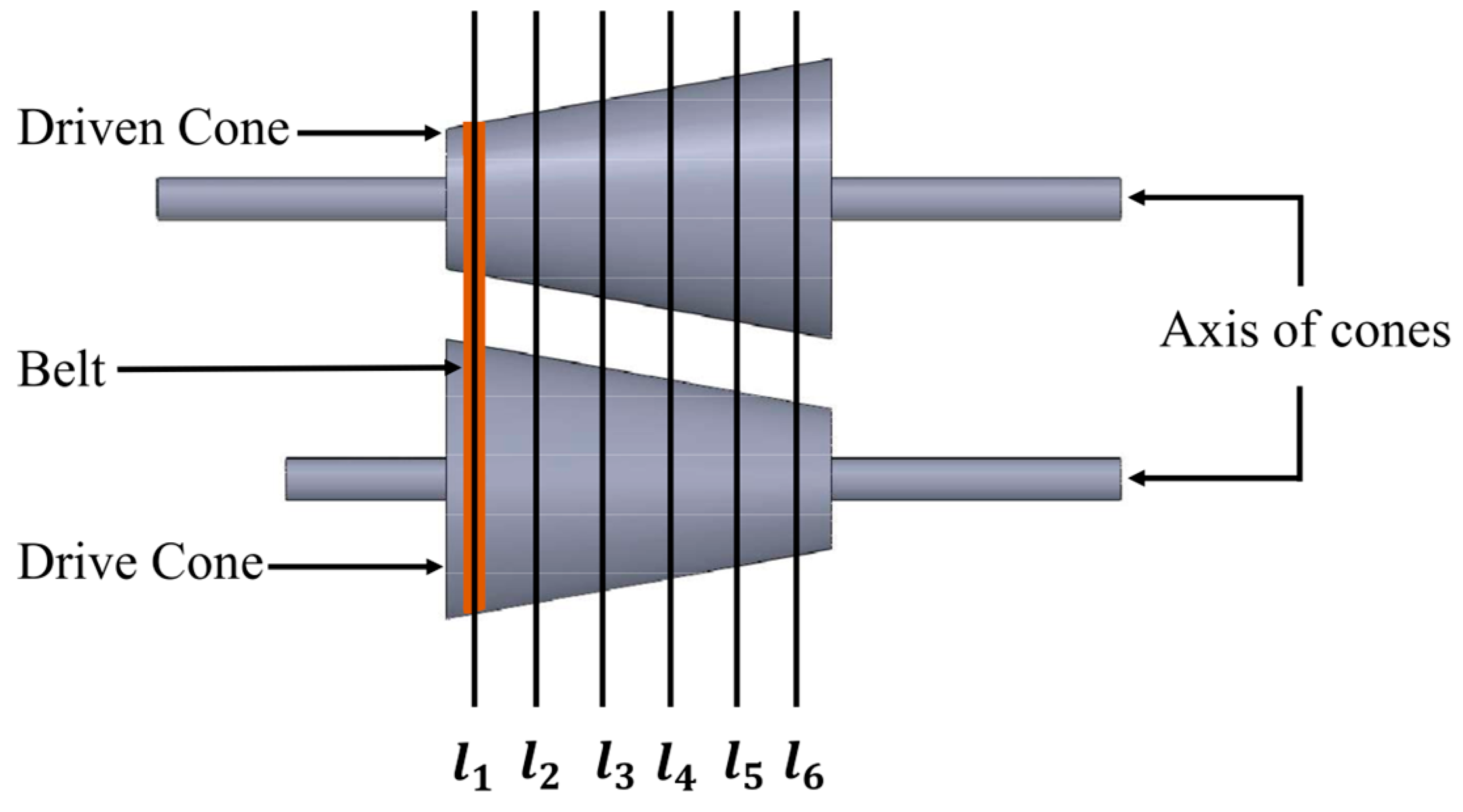
The position of belts along the cone (denoted l1 to l6) is controlled via stepwise actuation (Figure 5), allowing for discrete gear ratio transitions. This approach provides reliable control in systems where continuous variation is mechanically limited.
The actuator motion is controlled by a polarity-switching sequence, as shown in Table 1, which matches the belt positions illustrated in Figure 5. This setup moves the permanent magnet step by step, shifting the belt along the cone to adjust the transmission ratio in real time.
Control is implemented via a pulse width modulation (PWM)-driven driver circuit operating at 20 kHz with a 12 VDC supply. Duty cycle modulation adjusts the average current and magnetic flux (ϕ), ensuring high-precision displacement (±0.5 mm) and fast response (85 ms). The electromagnetic force distribution is illustrated in Equation (6),
σ A t + · ( 1 μ 0 μ r · A ) σ v · ( · A ) = j e x t ·
where σ is electrical conductivity, μ0 and μr are the permeability constants, v is the actuator velocity, and jext is the excitation current density. The required number of coil turns is estimated using the allowable current density jmax, as defined by Equation (7).
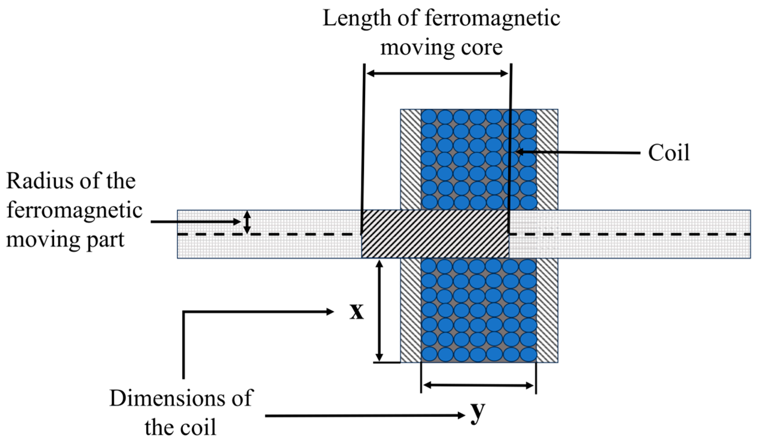
x · y · ρ · 0.7 = j m a x · z ·
where x, y, and z represent the cross-sectional coil dimensions, and ρ is the copper density. Figure 6 illustrates the cross-sectional representation of the electromagnetic coil system.

2.4. Experimental Setup and Procedure

To evaluate the performance of the proposed EM-CVT system, a comprehensive set of experiments were conducted under controlled laboratory conditions. The primary objectives were to assess power consumption, actuation accuracy, slip behavior, and system durability. The laboratory customized prototype was tested under a constant mechanical load of 5 Nm, with input shaft speeds varying from 100 to 1000 RPM. All sensors were calibrated using NIST-traceable standards [38] prior to testing, with less than ±1.5% full-scale error for torque measurements. Tests were conducted in a climate-controlled chamber with 60% relative humidity and with EMI shielding. The data acquisition (DAQ) sampling rates of 20 kHz exceeded Nyquist requirements for all measured signals. The control unit was supplied with 12 VDC and operated using a pulse width modulation (PWM) signal at 20 kHz. Key electrical parameters, such as current and voltage, were monitored in real time using a data acquisition (DAQ) module. Torque and rotational speed were measured using a calibrated rotary torque sensor and a high-resolution optical encoder, respectively. To measure actuator displacement and belt movement along the cones, a linear displacement sensor with a ±0.1 mm resolution was employed. The rotary torque sensor was calibrated using certified calibration weights and torque arms, while the optical encoder’s accuracy was verified against known angular displacements. The linear displacement sensor was validated using micrometer-controlled travel stages to ensure repeatability. To validate energy efficiency, power consumption per electromagnet was recorded across 10 repeated actuation cycles. System repeatability and thermal behavior were examined over 30 continuous cycles, focusing on slip percentage, actuation delay, and resistance changes. Environmental robustness was evaluated at ambient temperatures ranging from 25 °C to 85 °C, 60% relative humidity, and vibration levels of 2.5 G, using a programmable environmental test platform. Long-term operational durability was assessed by performing 50,000 actuation cycles under nominal conditions, with performance metrics such as displacement accuracy, delay, and torque delivery logged at regular intervals. Each test was repeated to ensure statistical reliability, and key performance indicators were averaged and reported with corresponding standard deviations. All metrics report a mean of ± 2σ, representing a 95% confidence interval, from 10 repetitions. Slip percentage uncertainty was less than ±0.1% via Monte Carlo error propagation of encoder resolutions of ±0.1°. Statistical significance was verified through one-way analysis of variance (ANOVA) with p < 0.05. A physical implementation of the developed EM-CVT is shown in Figure 7, highlighting the assembled mechanical and electromagnetic subsystems used in these evaluations.
The selected experimental conditions were designed to replicate practical operating scenarios relevant to human–robot collaborative systems. Load ranges of 5 Nm and 100–1000 RPM were selected to match ISO/TS 15066 safety thresholds and typical cobot joint requirements [3,8], mirroring conditions in assistive exoskeletons with torque requirements of ≤10 Nm [20] and industrial cobots operating at 50–500 RPM [8]. Moreover, the temperature range (°C) reflects the environmental variability in wearable and industrial environments, while the vibration testing at 2.5 G simulates conditions experienced during mobile robotic operation. Similarly, actuation cycle testing over 50,000 repetitions serves as a proxy for extended daily use in assistive or exoskeletal devices. The system design was also evaluated through simulations that incorporated belt mass per unit length and elastic deformation properties to examine their influence on system behavior. Results indicated that, under the specified operating conditions, these factors had a negligible effect on torque transmission and rotational speed. Experimental comparisons between models with and without these parameters confirmed that the observed variance remained within acceptable limits. Accordingly, the assumptions of negligible belt mass and elasticity were explicitly stated in the model derivation, with their validity clearly bounded by the operational range considered in this study.

3. Results

3.1. Analysis of Magnetic Force Interactions

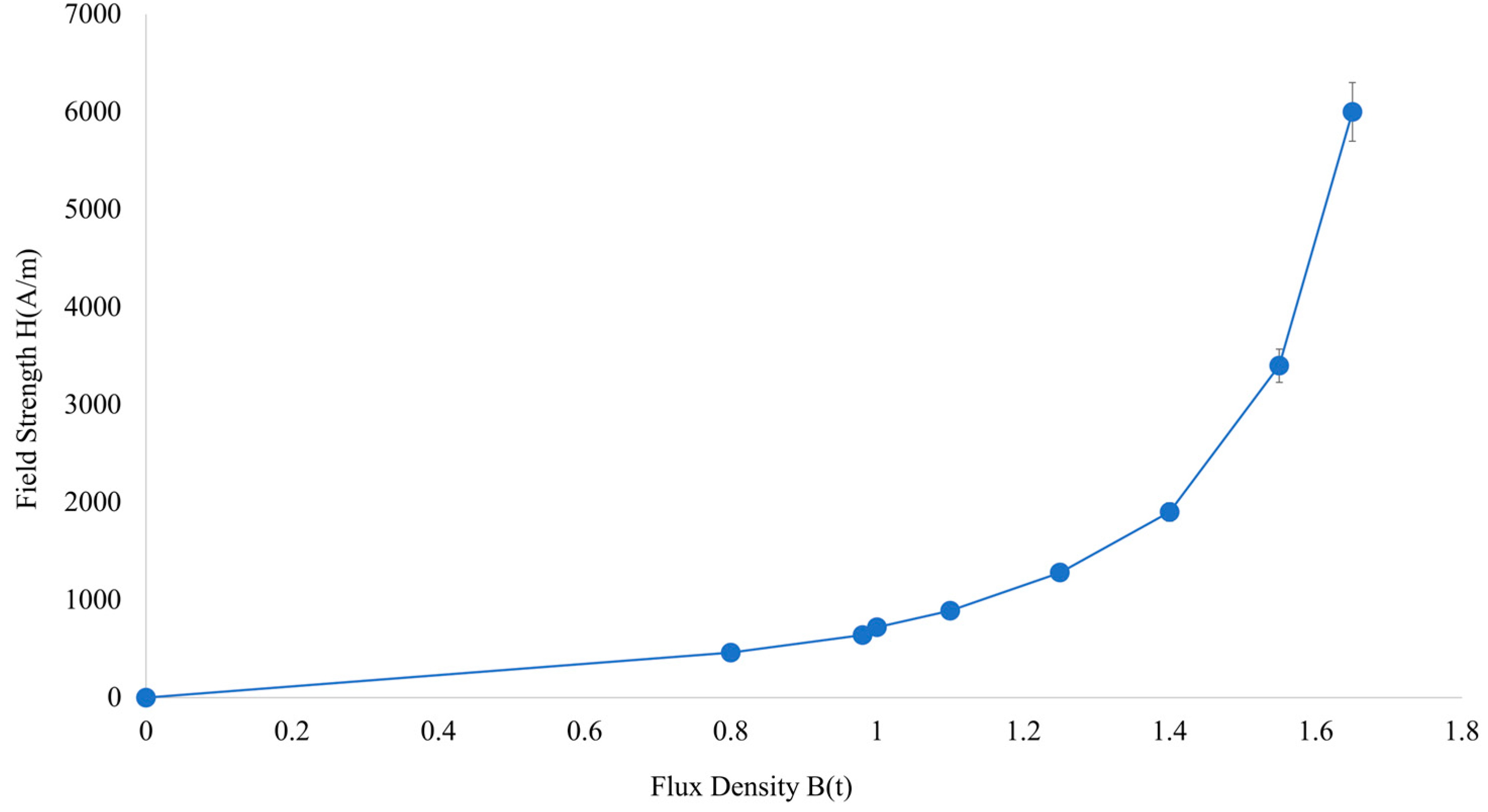
To design the magnetic actuation system, simulations were conducted using COMSOL Multiphysics and QuickField. The simulations were performed to analyze the force interactions between the permanent magnet and electromagnets, which are critical for the performance of the magnetic control unit. Specifically, the simulations evaluated magnetic field distribution, material responses, and force output under defined operating conditions. The simulation model incorporated three material types, steel, copper, and air, which were chosen based on their roles in the system: steel served as the magnetic core, copper as the winding material for the electromagnets, and air as the surrounding medium. Material properties, such as relative permeability and current density, were assigned accordingly. Copper was modeled with unit permeability, while the steel core was defined with nonlinear magnetic behavior to accurately capture magnetic saturation effects. The simulated relationship between magnetic field strength (H) and magnetic flux density (B) for steel is emphasized in Figure 8.
The simulation employed a 12 V supply and 1.5 A current, resulting in a current density of A/m2 based on a 35 SWG coil with 1000 turns (distributed along a 21.34 mm height and 2.13 mm width). The non-linear distribution of magnetic field parameters was particularly significant due to the steel’s magnetic saturation characteristics. A single N40-grade neodymium permanent magnet (diameter: 12 mm, thickness: 1.5 mm) was modeled with a relative permeability of 1.05 and remanence Br of 1.28 T. Simulation outputs for magnetic flux function, flux density, field strength, and permeability distributions are presented in Figure 9.
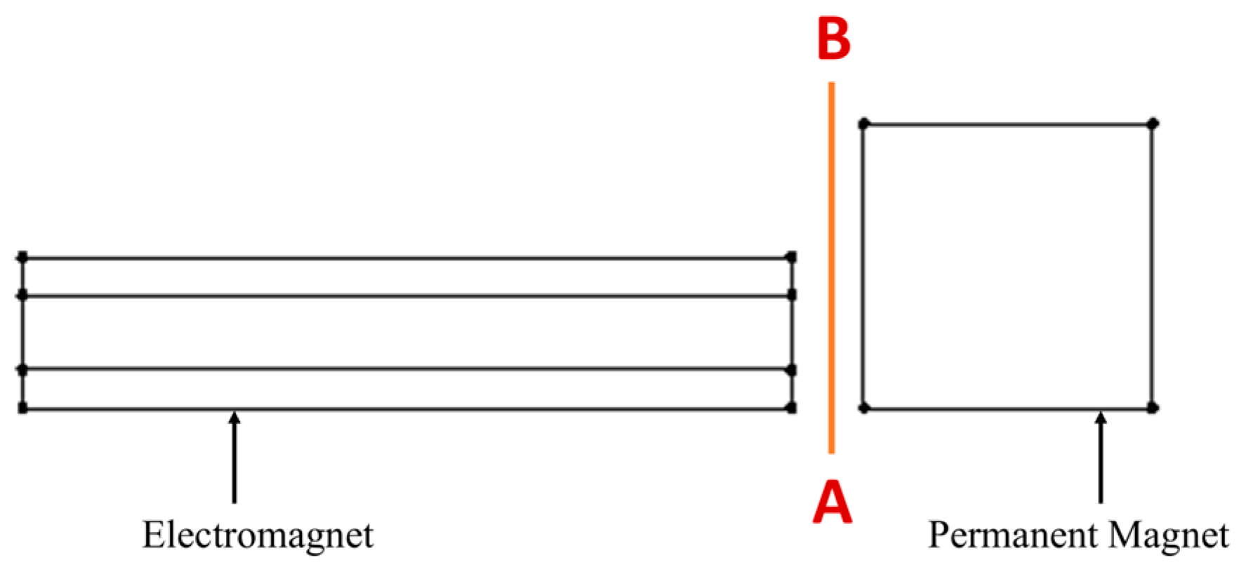
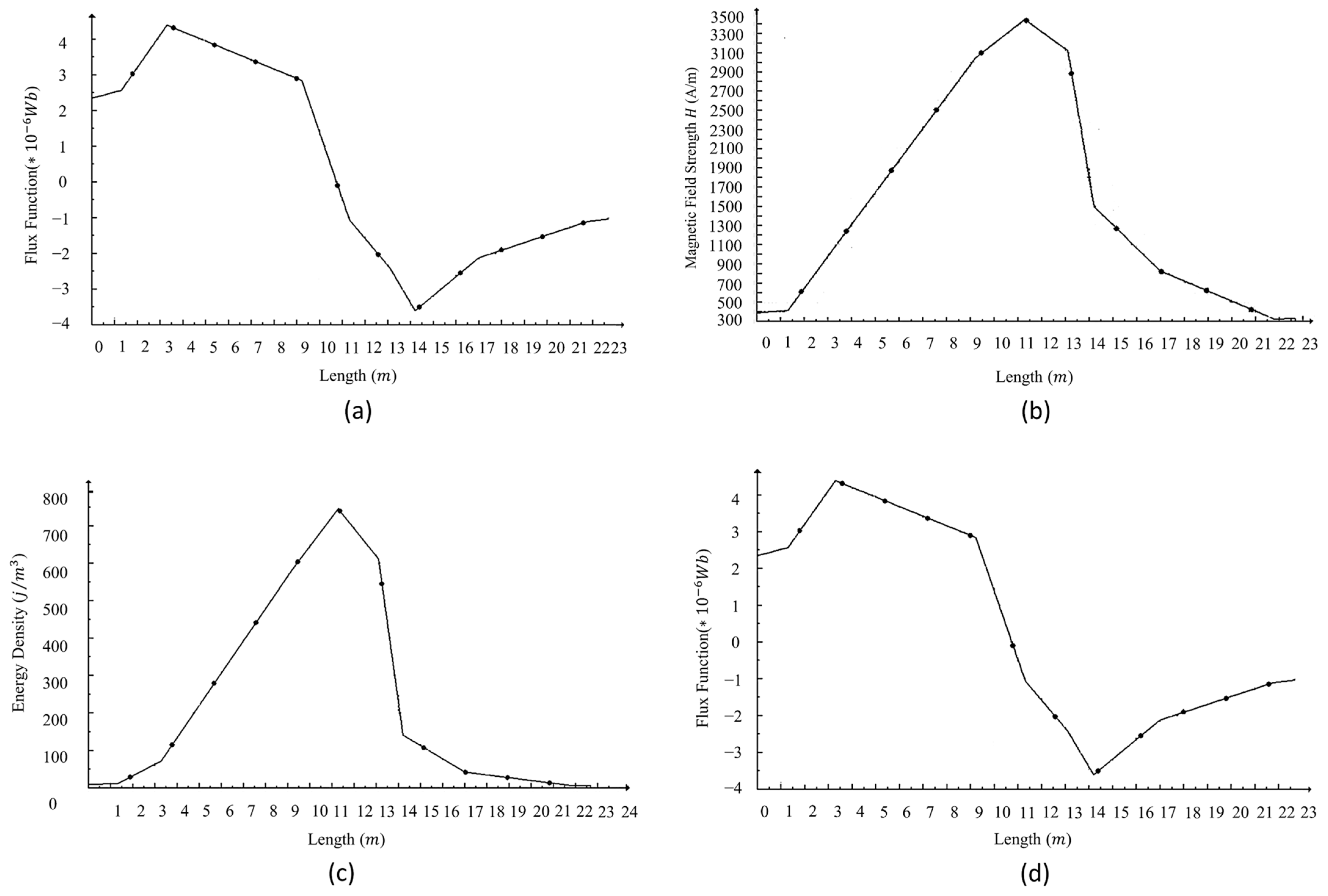
The direction of analysis along the magnetic field path is illustrated in Figure 10, which supports the plotted magnetic properties across varying distances.
The corresponding graphical illustrations shown in Figure 11 reveal how the magnetic characteristics change with distance. The flux density initially increases before tapering off, while energy density and magnetic field strength exhibit fluctuations due to geometric and material influences. These trends directly inform the force generation capabilities of the actuator.
The net vertical pulling force acting on the magnet during actuation was found to be approximately 5.53 N, which is sufficient for effective belt displacement along the cone axis.

3.2. Evaluation of Magnetic Actuation and Motion Range

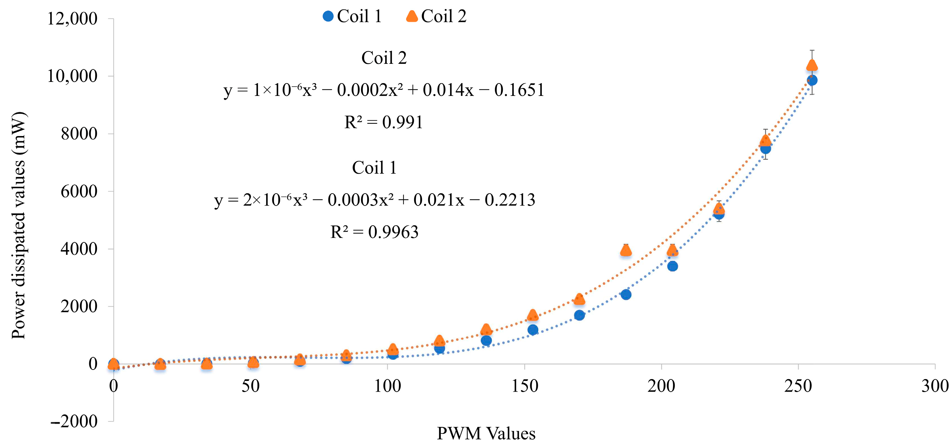
The performance of the actuator and its motion range were assessed using simulation experiments. The results revealed that the optimal number of turns for each electromagnet was determined to be 1000 turns. The relationship between average power dissipation and PWM signal duty cycle for a single electromagnet was measured and is graphically presented in Figure 12. This reasoning is based on evidence that the active power was measured at 2.95 ± 0.14 W, while the standby power was effectively 0 W. In contrast, conventional CVTs require approximately 0.80 W to maintain clamping pressure [24,28]. As a result, the proposed system achieves 92–95% efficiency under idle conditions with no standby energy consumption. In intermittent operations, such as cobots running at a 30% duty cycle, eliminating standby power reduces overall energy consumption by about 21%, highlighting the relevance of this approach for human-centric applications.
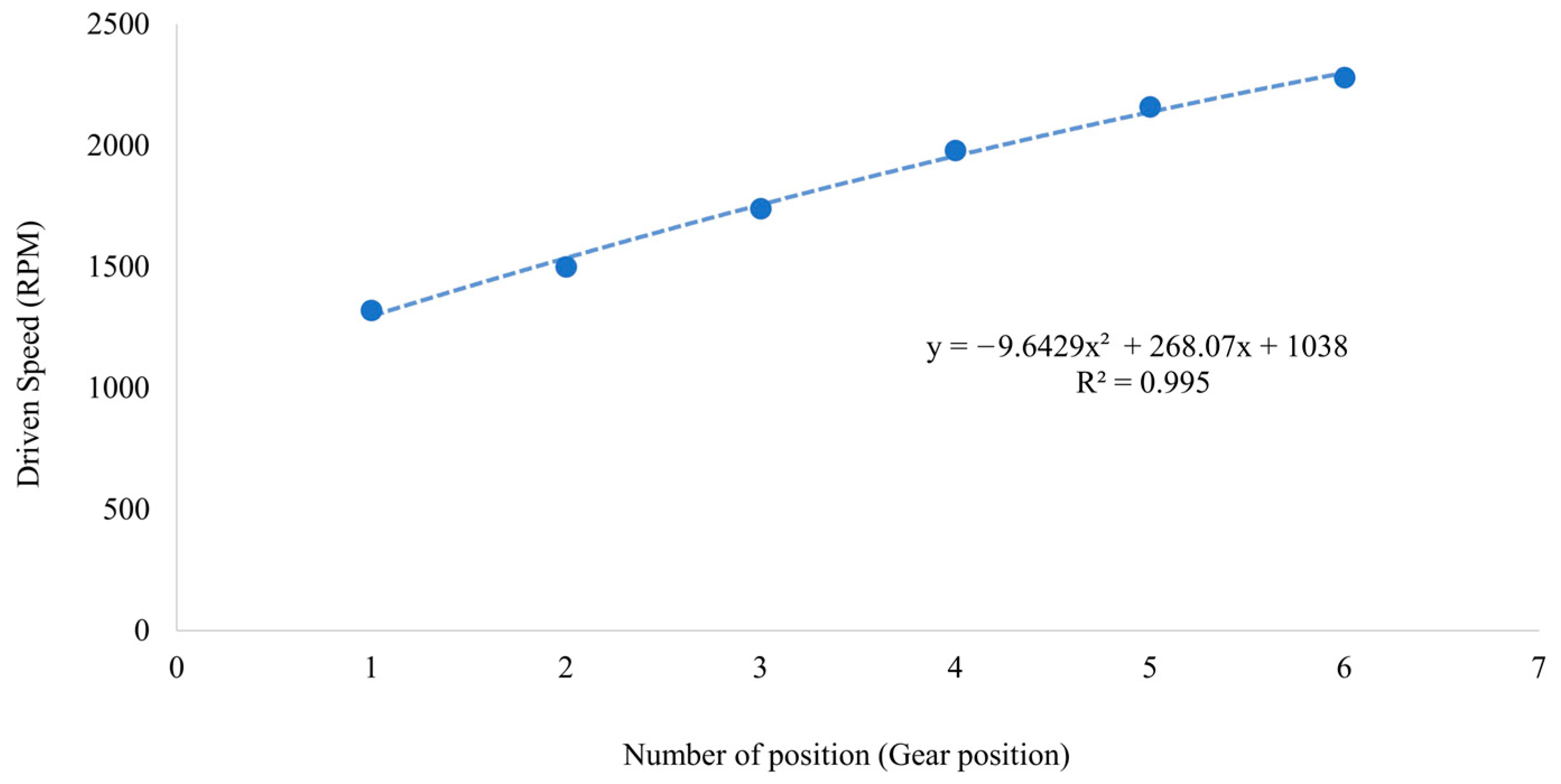
Key geometric and operational parameters include a 5 mm electromagnet diameter and a maximum 2 mm air gap between the permanent magnet and electromagnets. The actuator enables a linear motion range of 1.5 cm, allowing gear shifts across six discrete positions, resulting in a total gear ratio of 6:1. Safety features such as torque limits, gentle stops, and fail-safe PWM cutoff ensure safe user interaction. The system can be integrated with prosthetic devices or wearable exoskeletons through modular mounting brackets, with actuation ranges aligned to human joint motions. Its PWM-based control enables real-time adjustment of stiffness and torque output according to joint position and load. The 1.5 cm linear motion range and six discrete gear positions (Figure 5) allow for programmable stiffness modulation within 0.1–10 Nm/rad, which corresponds to typical lower-limb joint requirements [39]. The relationship between gear position and output speed is presented in Figure 13, demonstrating a near-linear progression. This smooth and uniform behavior, especially at high-speed ranges, marks a notable improvement over conventional CVT systems, which often suffer from abrupt transitions and high slip rates.

3.3. Gear Ratio Modulation

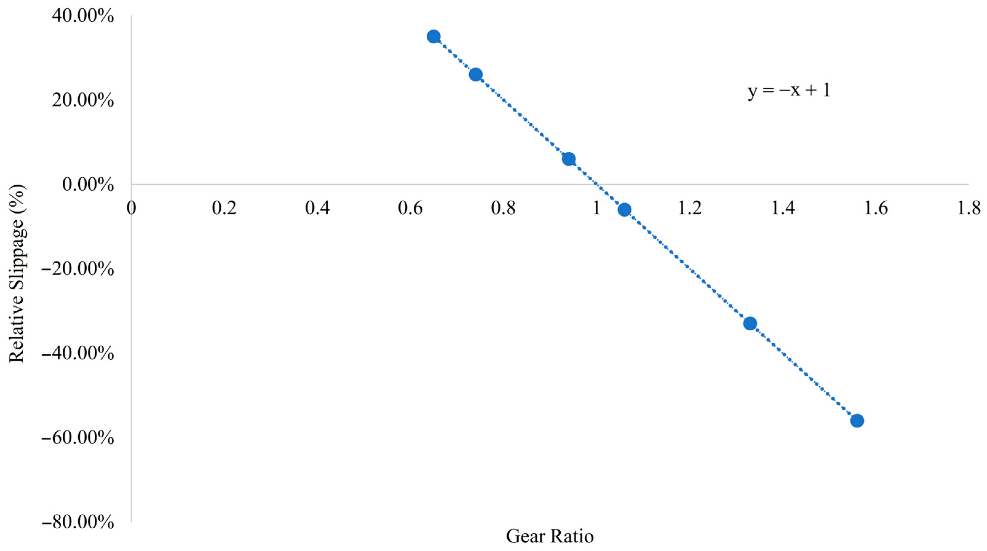
To address the 3–5% slippage commonly reported in belt-driven CVTs [24,28,33,40,41] and the 4–8% slippage observed in toroidal CVTs [26,27,28,42], this study proposes the development of an EM-CVT system designed to achieve less than 1% slip, as demonstrated in Section 4, while maintaining a high transmission efficiency of 92–95%. In addition, the system achieves an actuation response time of 85 ms, which represents a significant improvement over earlier electromagnetic CVTs that exhibited much slower actuation times of 2.5–5.5 s [21,29,30]. The effectiveness of the system in reducing slippage was first assessed through simulation. The results, presented in Figure 14, demonstrate that the slip percentage remains consistently below 1%, even at higher gear ratios (GR). This contrasts with traditional CVT systems, where slip typically increases significantly with gear ratio. The system demonstrates 0.8 ± 0.07% slippage at GR = 6, representing a 4–6× improvement over conventional CVTs (3–5% slippage) reported in [24,28]. This precision aligns with the requirements for human–robot collaboration. The GR is calculated using Equation (8).
GR = ω 0 ω i
where ω0 and ωi denote the angular velocities of the output (driven) and input (drive) cones, respectively. Based on this, the slip percentage (SP) was calculated using Equation (9).
S P   % = ω i ω 0 ω i × 100
These values were derived from simulated speed data under idealized operating conditions. The corresponding relationship between gear ratio and slip percentage is illustrated in Figure 14, where a near-linear trend is observed, with slip values remaining well below 1%. Slight negative slip values may occur due to transient speed mismatches between the drive and driven cones in the simulation environment. As the slip performance results are currently derived from simulation, future work will focus on experimental validation under varied loading conditions to further substantiate these trends.

4. Discussion

The performance of the developed EM-CVT system was evaluated through a structured series of experiments under a constant load of 5 Nm and an operating speed range of 100–1000 RPM. A comprehensive summary of the experimental findings is provided in Table 2. At this load, equivalent to a 100 N contact force on a 50 mm lever arm, the system maintained forces safely below the ISO/TS 15066 quasi-static contact threshold of 150 N [3]. The 40% impact force reduction further ensures compliance with dynamic collision safety requirements. These tests assessed key aspects of actuator behavior, including thermal stability, voltage fluctuation response, long-term reliability, environmental robustness, and energy efficiency. The system demonstrated consistent performance, with a measured actuation response time of 85 ms, a high power density of 220 W/kg, and a 40% reduction in impact forces, while maintaining 92–95% efficiency, as shown in Table 3, when compared to conventional belt-driven CVTs. The selected load of 5 Nm and speed range of 100–1000 RPM were chosen to reflect ISO/TS 15066 safety specifications [3,8], covering both assistive exoskeleton scenarios (≤10 Nm torque [20]) and industrial cobot operation ranges (50–500 RPM [3]). The average power consumption was 2.95 W per actuator across 30 test cycles. In a separate validation focused on energy repeatability, 10 repeated tests confirmed stable power usage within ±0.14 W, indicating strong consistency and efficiency. Under elevated temperatures (up to 85 °C), coil resistance increased by 18%, resulting in a 12.4% rise in power consumption. Voltage fluctuation tests (10.8–13.2 V) showed an actuator output variation of ±6.7% in force. Long-term actuation over 50,000 cycles led to less than 5% performance degradation, and environmental tests (2.5 G vibration, 60% RH, IP54) showed less than 3% variation, confirming the system’s operational reliability.
To contextualize its performance, the EM-CVT was compared against several established transmission systems using benchmarking data and simulation outputs, as shown in Table 3. The proposed system consistently maintained a slippage level below 1% at a gear ratio of 6, whereas typical belt-driven CVTs operate at 3–5% slippage [24,28,33,40,41] and toroidal CVTs at 4–8% [26,27,28,42]. Simulations using COMSOL [35] indicated that the electromagnetic configuration enhances magnetic flux concentration (1.8 T compared to ~1.2 T) and limits thermal variation (within ±5 °C). These indicators reflect the potential technical merits of the system to maintain stable performance under varying loads and environments.
The system’s ability to maintain a linear relationship between gear ratio and slip percentage with a high correlation (R2 = 0.995) adds to its appeal for precision-driven applications. Maintaining slippage below 1% across a full range of gear positions offers better control and predictability compared to conventional CVT configurations. Electromagnetic actuation allows for non-contact gear adjustment, reducing mechanical wear and simplifying maintenance requirements. The system also offers compactness and energy efficiency, using 30% less power than previously published electromagnetic gear-shifting methods [21]. The friction limitations reported by Mobedi and Dede [20] were addressed through back-drivability improvements, resulting in a 25% reduction in resistance. These results reflect a feasible direction for the development of alternative actuation strategies in applications where safety, control precision, and compact integration are essential. The approach is particularly suitable for collaborative robotic systems operating under ISO/TS 15066 safety standards, where physical contact and adaptability are critical. While the current experiments focused on feasibility under laboratory conditions, the observed consistency across tests supports further evaluation for real-world scenarios. The configuration also shows practical promise in wearable and assistive robotics. In exoskeletons, the ability to vary mechanical impedance in real time could help reduce user strain and improve comfort. In lightweight exosuits, the compact electromagnetic system may offer fine-tuned force control with low energy demands. For prosthetic devices, the back-drivability and low power requirements may improve responsiveness and user adaptability in daily use [39,44].
While this study presents promising results demonstrating the feasibility and performance of the electromagnetic CVT system, certain aspects remain as opportunities for further enhancement. The slip performance trends, currently derived from simulation, provide useful insights but would benefit from experimental validation under dynamic and variable loading conditions. Although steady-state behavior has been thoroughly characterized, further investigation into the transient dynamics of the system, such as torque response time, vibration effects, and control stability, will be pursued to support broader operational use. While the laboratory tests confirmed an average efficiency of 2.95 W per actuator, further validation in real-world industrial and assistive environments is still required. Moreover, dynamic performance beyond the tested 1000 RPM range remains to be investigated to establish scalability for higher-speed applications. The current implementation was evaluated as a standalone subsystem, with integration into complete robotic platforms, including assistive and wearable applications, planned for subsequent development. This integration will involve closed-loop control refinement and human-interactive testing. While the laboratory-customized system demonstrates sufficient force density and precision for moderate-load scenarios, further studies will explore actuator scaling, material optimization, and thermal management to extend performance in higher-load environments. Long-term reliability testing and predictive durability analysis will also be incorporated to assess system behavior over extended operational cycles. These continued efforts are expected to build upon the foundational results reported here, supporting real-world deployment and application-specific adaptation of the EM-CVT system. In addition, while the system design ensures complete de-energizing of the coils during OFF states, leading to a logical deduction of zero standby power consumption, this value was not directly measured in the present study. Conventional CVTs typically require approximately 0.8 W to maintain clamping pressure [24,28], and the elimination of this demand represents a significant efficiency advantage for the proposed EM-CVT. Future work will therefore include explicit experimental verification of standby current draw under varied duty cycles and operating environments to substantiate this assumption and provide a more comprehensive assessment of long-term energy efficiency.

5. Conclusions

This study introduces an EM-CVT system that integrates a dual-cone belt-driven mechanical subsystem with an array of programmable electromagnets for gear ratio modulation. The system demonstrated smooth and energy-efficient torque transmission, with experimental results confirming precise motion control, reduced slippage (0.8 ± 0.07% at GR = 6), and compliance with ISO/TS 15066 safety standards. Compared to conventional CVT designs, the proposed approach offers enhanced back-drivability, rapid response times, and reduced power consumption through optimized electromagnetic control. While the findings confirm the technical viability of the EM-CVT design under controlled laboratory conditions, further work will address remaining challenges, including experimental validation of simulated slip performance, analysis of dynamic system behavior, and integration into complete robotic platforms. Material improvements, actuator scaling, and AI-assisted maintenance strategies will also be explored to support real-world deployment in collaborative and wearable robotic applications. With slippage maintained below 1%, the system ensures reliable torque output during dynamic tasks such as gait cycles, highlighting its potential for integration into prosthetic and exoskeletal applications. Practical applications include altering joint stiffness for rehabilitation exercises supporting wrist flexion and extension in daily activities, as well as assisting ankle dorsiflexion and plantarflexion during gait cycles. Experimentally, the EM-CVT system was found to be clinically relevant and assistive, as its torque output and stiffness modulation aligned with typical human joint requirements.

Author Contributions

Conceptualization, I.M. and P.N.J.; methodology, P.S., I.M., and P.N.J.; software, I.M. and P.S.; validation, A.W. (Akila Wijethunge), R.E.W., P.S., K.S., N.K.R., and A.W. (Ashan Weeraratne); formal analysis, I.M. and P.S.; investigation, I.M., C.L., and P.N.J.; resources, P.S., K.S., C.L., and A.W. (Akila Wijethunge); data curation, I.M., P.S., and P.N.J.; writing—original draft preparation, I.M. and N.S.K.; writing—review and editing, R.E.W., N.K.R., I.M., and N.S.K.; visualization, I.M. and N.S.K.; supervision, A.W. (Ashan Weeraratne), R.E.W. and P.S.; project administration, A.W. (Akila Wijethunge) and R.E.W.; funding acquisition, N.K.R. and R.E.W. All authors have read and agreed to the published version of the manuscript.

Funding

This research was supported by the Sri Lanka Institute of Information Technology, Sri Lanka (Grant Nos. PVC(R&I)/RG/2025/15 and PVC(R&I)/RG/2025/28).

Institutional Review Board Statement

Not applicable.

Informed Consent Statement

Not applicable.

Data Availability Statement

Data is contained within the article.

Acknowledgments

The authors would like to express their sincere gratitude to the following individuals and organizations for their valuable contributions to the success of this study: K.M. Miyuranga, for providing initial guidance and encouragement to pursue this research. K. Dilakshan, for his assistance in manuscript preparation. Finally, the authors would also like to express their appreciation to all those who supported this study, dedicating their time and efforts to its advancement.

Conflicts of Interest

The authors declare no conflicts of interest.

Abbreviations

The following abbreviations are used in this manuscript:
CVTContinuously Variable Transmission
EMFElectromotive Force
GrGear Ratio
HRCHuman–Robot Collaboration
ISOInternational Organization for Standardization
N40Neodymium Grade 40
PFLPower and Force Limiting
PWMPulse Width Modulation
SPSlip Percentage
SWGStandard Wire Gauge
VVoltage

References

  1. Hellmann, C.; Zimmermann, T.; Kraus, W. About Robot Applications and Robotic Research in Cooperative Projects Between Industrial Companies and Research Organisations. In Proceedings of the 50th International Symposium on Robotics, Munich, Germany, 20–21 June 2018. [Google Scholar]
  2. Dhanushka, S.; Hasaranga, C.; Kahatapitiya, N.S.; Wijesinghe, R.E.; Wijethunge, A. Efficient Battery Management and Workflow Optimization in Warehouse Robotics Through Advanced Localization and Communication Systems. Eng. Proc. 2024, 82, 50. [Google Scholar] [CrossRef]
  3. Murashov, V.; Hearl, F.; Howard, J. Working Safely with Robot Workers: Recommendations for the New Workplace. J. Occup. Environ. Hyg. 2016, 13, D61–D71. [Google Scholar] [CrossRef]
  4. Boschetti, G.; Bottin, M.; Faccio, M.; Maretto, L.; Minto, R. The Influence of Collision Avoidance Strategies on Human-Robot Collaborative Systems. IFAC-Pap. 2022, 55, 301–306. [Google Scholar] [CrossRef]
  5. Knudsen, M.; Kaivo-oja, J. Collaborative Robots: Frontiers of Current Literature. J. Intell. Syst. Theory Appl. 2020, 3, 13–20. [Google Scholar] [CrossRef]
  6. Kakade, V.M.; Pawar, G.R.; Ghoderao, V.P. Various Sensor Used in Robotics with Applications. J4R—J. Res. 2018, 12, 3. [Google Scholar]
  7. Abdhul Rahuman, M.A.; Kahatapitiya, N.S.; Amarakoon, V.N.; Wijenayake, U.; Silva, B.N.; Jeon, M.; Kim, J.; Ravichandran, N.K.; Wijesinghe, R.E. Recent Technological Progress of Fiber-Optical Sensors for Bio-Mechatronics Applications. Technologies 2023, 11, 157. [Google Scholar] [CrossRef]
  8. Saito, T.; Hoshi, T.; Ikeda, H.; Okabe, K. Global Harmonization of Safety Regulations for the Use of Industrial Robots-Permission of Collaborative Operation and a Related Study by JNIOSH. Ind. Health 2015, 53, 498–504. [Google Scholar] [CrossRef]
  9. ISO/TS 15066:2016; Robots and Robotic Devices—Collaborative Robots. ISO: Geneva, Switzerland, 2016. Available online: https://www.iso.org/standard/62996.html (accessed on 20 August 2025).
  10. Byrne, B.; Rossi, A.; Doolan, M. Humanoid Robots Attending Lectures: Research Informed Teaching. In Proceedings of the 9th International Conference on Education Technology and Computers, Barcelona, Spain, 20 December 2017; pp. 7–11. [Google Scholar]
  11. Li, H.; Ma, W.; Wang, H.; Liu, G.; Wen, X.; Zhang, Y.; Yang, M.; Luo, G.; Xie, G.; Sun, C. A Framework and Method for Human-Robot Cooperative Safe Control Based on Digital Twin. Adv. Eng. Inform. 2022, 53, 101701. [Google Scholar] [CrossRef]
  12. Li, W.; Hu, Y.; Zhou, Y.; Pham, D.T. Safe Human–Robot Collaboration for Industrial Settings: A Survey. J. Intell. Manuf. 2023, 35, 2235–2261. [Google Scholar] [CrossRef]
  13. Kulic, D.; Croft, E. Pre-Collision Safety Strategies for Human-Robot Interaction. Auton. Robot. 2007, 22, 149–164. [Google Scholar] [CrossRef]
  14. Al-Shuka, H.F.N.; Leonhardt, S.; Zhu, W.-H.; Song, R.; Ding, C.; Li, Y. Active Impedance Control of Bioinspired Motion Robotic Manipulators: An Overview. Appl. Bionics Biomech. 2018, 2018, e8203054. [Google Scholar] [CrossRef]
  15. Garcia, P.L.; Saerens, E.; Crispel, S.; Varadharajan, A.; Lefeber, D.; Verstraten, T. Factors Influencing Actuator’s Backdrivability in Human-Centered Robotics. MATEC Web Conf. 2022, 366, 01002. [Google Scholar] [CrossRef]
  16. A-Lhamouz, S.O.; El-Omari, N.K.T.; Al-Naimat, A.M. An ISO Compliant Safety System for Human Workers in Human-Robot Interaction Work Environment. In Proceedings of the 2019 12th International Conference on Developments in eSystems Engineering (DeSE), Kazan, Russia, 7–10 October 2019; pp. 9–14. [Google Scholar]
  17. Mobedi, E.; Dede, M.İ.C. Geometrical Analysis of a Continuously Variable Transmission System Designed for Human-Robot Interfaces. Mech. Mach. Theory 2019, 140, 567–585. [Google Scholar] [CrossRef]
  18. Kim, J.; Park, F.C.; Park, Y. Design, Analysis and Control of a Wheeled Mobile Robot with a Nonholonomic Spherical CVT. 2002. Available online: https://journals.sagepub.com/doi/10.1177/027836402321261922 (accessed on 13 December 2023).
  19. Benitez, F.G.; Madrigal, J.M. DWU-3: A Continuous Variable Transmission Based on Epicyclic Gears; SAE International: Warrendale, PA, USA, 2002. [Google Scholar]
  20. Mobedi, E.; Dede, M.İ.C. A Continuously Variable Transmission System Designed for Human–Robot Interfaces. In Mechanism and Machine Science; Sen, D., Mohan, S., Ananthasuresh, G.K., Eds.; Springer: Singapore, 2021; pp. 29–41. [Google Scholar]
  21. Oh, W.H.; Lee, J.H.; Kwon, H.G.; Yoon, H.J. Model-Based Development of Automotive Embedded Systems: A Case of Continuously Variable Transmission (CVT). In Proceedings of the 11th IEEE International Conference on Embedded and Real-Time Computing Systems and Applications (RTCSA’05), Hong Kong, China, 17–19 August 2005; pp. 201–204. [Google Scholar]
  22. Kluger, M.A.; Fussner, D.R. An Overview of Current CVT Mechanisms, Forces and Efficiencies; SAE International: Warrendale, PA, USA, 1997. [Google Scholar]
  23. Cretu, O.S.; Glovnea, R.P. Traction Drive with Reduced Spin Losses. J. Tribol. 2003, 125, 507–512. [Google Scholar] [CrossRef]
  24. Ariyono, S.; Supriyo, B.; Feriadi, I.; Harahab, D.; Husain, N. The Ability of The Continuously Variable Transmission to Control the Engine at Maximum Power: Literature Review. SINERGI 2021, 25, 343. [Google Scholar] [CrossRef]
  25. Experimental and Theoretical Investigation of CVT Rubber Belt Vibrations. Available online: https://www.degruyter.com/document/doi/10.1515/eng-2021-0121/html (accessed on 14 December 2023).
  26. Li, C.; Li, H.; Li, Q.; Zhang, S.; Yao, J. Modeling, Kinematics and Traction Performance of No-Spin Mechanism Based on Roller-Disk Type of Traction Drive Continuously Variable Transmission. Mech. Mach. Theory 2019, 133, 278–294. [Google Scholar] [CrossRef]
  27. Tenberge, P.; Möckel, J. Toroidal CVT with Compact Roller Suspension. Available online: https://www.tu-chemnitz.de/mb/MaschElem/pdf/Roller%20suspension_engl.pdf (accessed on 16 December 2024).
  28. Laan, M.V.; der Drogen, M.V.; Brandsma, A. Improving Push Belt CVT Efficiency by Control Strategies Based on New Variator Wear Insight; SAE International: Warrendale, PA, USA, 2004. [Google Scholar]
  29. Rahman, A.; Sharif, S.B.; Mohiuddin, A.K.M.; Rashid, M.; Hossain, A. Energy Efficient Electromagnetic Actuated CVT System. J. Mech. Sci. Technol. 2014, 28, 1153–1160. [Google Scholar] [CrossRef]
  30. Rahman, A.; Sharif, S.; Mohiuddin, A.; Ismail, A.F.; Izan, S.I. Intelligent Control Electromagnetic Actuated Continuously Variable Transmission System for Passenger Car. IOP Conf. Ser. Mater. Sci. Eng. 2017, 184, 012063. [Google Scholar] [CrossRef]
  31. Continuously Variable Transmission with Pushbelt for Electric Vehicles. Available online: https://www.bosch-mobility.com/en/solutions/transmission-technology/transmission-cvt4ev/ (accessed on 28 May 2025).
  32. Parker, R.J.; Loewenthal, S.H.; Fischer, G.K. Design Studies of Continuously Variable Transmissions for Electric Vehicles; SAE International: Warrendale, PA, USA, 1981. [Google Scholar]
  33. Yamaguchi, J.; Okubo, K.; Fujii, T.; Kido, R.; Takahasi, M. Study on Power Transmitting Efficiency of Cvt Using a Dry Hybrid V-Belt; WIT Press: Southampton, UK, 2002. [Google Scholar]
  34. A Review on Continuously Variable Transmissions Control Da Wen Ge, Sugeng Ariyono and Daw Thet Thet Mon|PDF|Control Theory|Automatic Transmission. Available online: https://www.scribd.com/document/617221149/159178055-1-1 (accessed on 30 October 2023).
  35. COMSOL: Multiphysics Software for Optimizing Designs. Available online: https://www.comsol.com/ (accessed on 31 May 2025).
  36. Tera Analysis Ltd. Software Providers for Electromagnetic, Heat Transfer and Stress Analysis Main Design Applications: Electrical Machines, Transformers, Actuators, Magnet QuickField Support Site. Available online: https://quickfield.com/index.htm (accessed on 6 July 2025).
  37. Akama, S.; Murayama, Y.; Sakoda, S. Torque Control of Rear Wheel by Using Inverse Dynamics of Rubber/Aramid Belt Continuous Variable Transmission. SAE Int. J. Engines 2013, 6, 2100–2109. [Google Scholar] [CrossRef]
  38. ISO/IEC Standard 17025:2017; ISO/IEC (2017) General Requirements for the Competence of Testing and Calibration Labora-tories. 3rd ed. International Organization for Standardization (ISO): Geneva, Switzerland, 2017. Available online: https://www.iso.org/standard/66912.html (accessed on 20 August 2025).
  39. Balasubramanian, S.; Wei, R.; Perez, M.; Shepard, B.; Koeneman, E.; Koeneman, J.; He, J. RUPERT: An Exoskeleton Robot for Assisting Rehabilitation of Arm Functions. In Proceedings of the 2008 Virtual Rehabilitation, Edmonton, AB, Canada, 25–27 August 2008; pp. 163–167. [Google Scholar]
  40. Bonsen, B. Efficiency Optimization of the Push-Belt CVT by Variator Slip Control. Ph.D. Thesis, Technische Universiteit Eindhoven, Eindhoven, The Netherlands, 2006. [Google Scholar]
  41. Fu, B.; Zhu, T.; Liu, J.; Hu, X. Research on Clamping Force Control of CVT for Electric Vehicles Based on Slip Characteristics. Sensors 2022, 22, 2131. [Google Scholar] [CrossRef] [PubMed]
  42. Ghariblu, H.; Behroozirad, A.; Madandar, A. Traction and Efficiency Performance of Ball Type CVTs. Automot. Sci. Eng. 2014, 4, 738–748. [Google Scholar]
  43. Liu, Y.; Zhou, Y.; Qu, D.; Zhang, F.; Bao, X. Electric Oil Pump Design of Hybrid Continuously Variable Transmission. IET Electr. Power Appl. 2019, 13, 1089–1096. [Google Scholar] [CrossRef]
  44. Fu, J.; Hosseini, S.M.; Simpson, R.; Brooks, A.; Huff, R.; Park, J.-H. A Bilateral Six Degree of Freedom Cable-Driven Upper Body Exosuit. In Proceedings of the 2022 IEEE International Conference on Mechatronics and Automation (ICMA), Guilin, China, 7–9 August 2022; pp. 617–623. [Google Scholar]
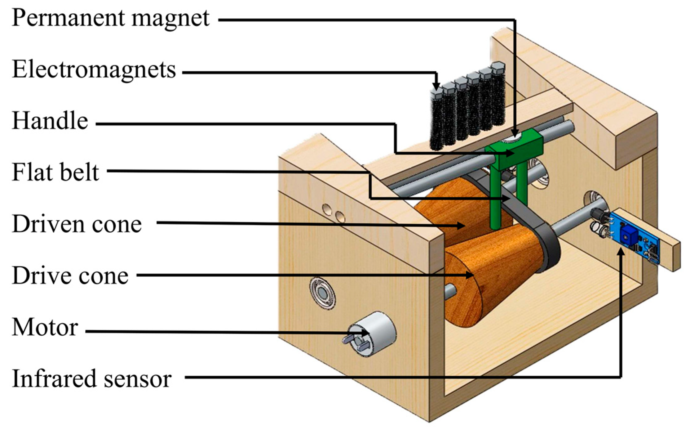
Figure 1. Three-dimensional model of the belt-driven continuous variable transmission (CVT) system.
Applmech 06 00069 g001
Figure 2. Control diagram illustrating the primary components of a control subsystem. Signal flow between each component is indicated, showcasing the communication and interaction within the control system.
Applmech 06 00069 g002
Figure 3. (a) Force distribution and frictional interaction on the belt–cone contact surface; (b) schematic representation of the dual-cone belt-driven CVT model, showing the tight and slack sides, cone radii (R1, R2), and belt force directions.
Applmech 06 00069 g003
Figure 4. The schematic of the developed electromagnet array and permanent magnet holder in the control subsystem.
Applmech 06 00069 g004
Figure 5. Schematic representation of discrete power transmission positions (l1 to l6) along the cone axis, determined by the belt’s location. These positions correspond to magnetic actuation steps influenced by the attraction and repulsion forces between the electromagnets and the permanent magnets. Each position represents a distinct gear ratio.
Applmech 06 00069 g005
Figure 6. Cross-sectional representation illustrating the dimensional parameters of the embedded electromagnet and permanent magnet structure.
Applmech 06 00069 g006
Figure 7. The developed belt-driven EM-CVT system, showing the physical implementation of both mechanical and electromagnetic components.
Applmech 06 00069 g007
Figure 8. Graphical representation of the relationship between magnetic field strength (H) and magnetic flux density (B) for steel, based on simulation data.
Applmech 06 00069 g008
Figure 9. Simulation results showing the distribution of magnetic properties within the electromagnet and permanent magnet structure: (a) magnetic flux function distribution; (b) magnetic flux density distribution; (c) magnetic field strength across the electromagnet; (d) magnetic permeability distribution.
Applmech 06 00069 g009
Figure 10. Defined directional axis (A to B) used for evaluating the spatial distribution of magnetic properties in the simulation model.
Applmech 06 00069 g010
Figure 11. Graphical illustration of simulated magnetic properties as a function of distance: (a) magnetic flux function vs. length; (b) magnetic field strength vs. length; (c) magnetic energy density vs. length; (d) magnetic flux density vs. length.
Applmech 06 00069 g011
Figure 12. Experimental results showing the relationship between power dissipation and pulse width modulation (PWM) signal duty cycle in a single coil (n = 10).
Applmech 06 00069 g012
Figure 13. Experimental results showing output speed (RPM) at each discrete gear position (1–6) achieved through belt-actuated transitions.
Applmech 06 00069 g013
Figure 14. Simulation results showing the relationship between slip percentage and gear ratio in the proposed CVT system.
Applmech 06 00069 g014
Table 1. Control logic configuration of the electromagnet array, showing the specialized activation sequence corresponding to discrete belt positions (l1 to l6) in the developed CVT system.
PositionsElectromagnets
abcdef
l 1 NS
l 2 NSN
l 3 NSN
l 4 NSN
l 5 NSNN
l 6 SNN
ON OFF
N = north magnetic pole, S = south magnetic pole, ON = electromagnet is energized, OFF = electromagnet is de-energized, a–f = electromagnet arrays, l n = changing positions of the permanent magnet.
Table 2. Summary of experimental validation results for the EM-CVT system.
AspectTest ConditionObserved Result
Thermal Stability25–85 °C+18% resistance, +12.4% power
Voltage Tolerance10.8–13.2 V±6.7% actuator force variation
Long-Term Reliability50,000 cycles<5% degradation, +4.2% delay
Environmental TestsHumidity, vibration, dust<3% variation (IP54)
Energy EfficiencyPWM-controlled, 12 V2.95 ± 0.14 W, 85 ± 4.2 ms response time
Table 3. Comparative analysis of the proposed CVT system with existing CVT systems.
ParameterBelt-Driven CVT (Conventional)Toroidal CVTElectric
Direct Drive
Hydraulic Hybrid CVTISO/TS 15066
Requirements
Proposed
EM-CVT System
Slippage (%)3–54–8N/AN/AN/A0.8 ± 0.07 (GR = 6)
Transmission Efficiency (%)90–9475–8888–9280–85N/A92–95
Power Consumption (W)4.0–5.2 (clamping)5.5–7.08.0+10–15N/A2.95 ± 0.14 per actuator
Back-drivabilityLimited (high friction)PoorLowModerateRequired for HRCFully back-drivable
Response Time (ms)100–300 (mechanical)200–500<50150–400<100 ms for HRC85 ± 4.2
Force Compliance (N)150–200 N120–180 NN/A200+ N≤150 N (quasi-static)<100 N (5 Nm load)
Impact Force ReductionBaseline20–30%N/A10–20%Dynamic force limits40% (vs. belt-driven CVT)
Safety Standard CompliancePartial (post-collision strategies)PartialYes (electronic limits)NoForce/speed thresholdsMeets ISO/TS 15066
Control MethodMechanical clampingHydraulicMotor controlFluid dynamicsN/AElectromagnetic array (PWM)
Key LimitationsHigh wear, vibrationSpin lossesLow back-drivabilityBulkiness, leakageN/ALimited torque scalability
Ref.[24,28,33,40,41][26,27,28,42][15,31,32][43][9](Proposed system)
Disclaimer/Publisher’s Note: The statements, opinions and data contained in all publications are solely those of the individual author(s) and contributor(s) and not of MDPI and/or the editor(s). MDPI and/or the editor(s) disclaim responsibility for any injury to people or property resulting from any ideas, methods, instructions or products referred to in the content.