1. Introduction
Wind energy, which has been booming for more than a decade, accounts for a significant percentage of the global energy market. In its latest report for 2021, the Global Wind Energy Council (GWEC) indicates a total capacity of 743 GW of wind turbines installed in the world, of which there were 93 GW of new installations in 2020 alone; among these, 86.9 GW of turbines were installed on land (onshore) and 6.1 GW were installed at sea (offshore) [
1]. All these turbines have to operate under various conditions, including salt water, sand particles, insects, lightning, ultraviolet rays, icing, and hot or cold temperatures, depending on the geographical location of the wind-power installations. These factors have an impact on the structure, and the wind turbines must also be regularly inspected to ensure that they are functioning properly and, therefore, producing the estimated energy and meeting the electricity demand. In other words, the inspection can be used to detect the defects in a structure before a failure occurs and prevent stops to energy production.
Wind turbines are increasingly used in northern regions because these regions are characterized by their high wind potential [
2]. Therefore, the technology has to adapt to the harsh climatic conditions, including extreme temperatures and icing (the phenomenon of ice accumulation on the blades of wind turbines) which, among other things, complicates the operation and maintenance of turbines in these locations [
3,
4]. However, wind farm operators prefer to mitigate the risks rather than avoid these regions, since they contain the greatest wind potential on the planet [
4,
5]. When wind turbines are operated in northern regions’ environmental conditions or the mounts, the blades and turbines are also subject to extreme temperatures and icing. Extreme temperatures affect the material used to manufacture the blades, and the blades can become brittle at very low temperatures, crack, or suffer from other damage due to extreme temperatures. Wind-turbine manufacturers are currently able to propose solutions to the severe temperature constraints induced by extreme temperatures in the design, manufacturing, operation, and maintenance (O&M) of wind turbines [
6,
7]. The vast majority of problems related to cold weather are, therefore, due to the accumulation of ice on wind turbines [
8]. This ice accumulation on the blades increases the stress on the blades, causes significant vibrations that lead to material fatigue, and can also cause damage [
9]. Therefore, to ensure sustainable operational conditions in northern climates, the proper choice of blade material is necessary, as well as an appropriate design and manufacturing process, adapted to the harsh winter conditions, and the ability to withstand additional loads due to ice accumulation on the blades. In addition, regular inspection is necessary to ensure the good condition of the blades, detect cracks and failures in time to react and plan repairs, and to ensure the proper functioning of the blades and, consequently, maintain expected energy production.
Canada, as one of the coldest countries in the world, has one of the highest wind-energy potentials in the world. The provinces with the highest wind-energy production are Ontario, Québec, and Alberta. According to CanWEA, in Canada, the 12,239 MW of installed capacity translates into 6409 wind turbines and, therefore, 19,227 blades that require regular inspection and maintenance. Ontario, Quebec, and Alberta share 2515, 1879, and 901 installed wind turbines, respectively; thus, they have 7545, 5637, and 2703 blades, respectively, to inspect and maintain [
10]. According to the Government of Quebec [
11], the province had 3879 MW of installed wind-power capacity in 2020 (i.e., 1935 turbines integrated and connected to the Hydro-Quebec grid) and is expected to have 3933 MW of wind power by 2022. Therefore, a large number of wind turbines are installed and operated under harsh climatic conditions (i.e., icing and very low temperatures), whose inspection is necessary and of high importance to ensure proper functioning during winter periods (where there is a surplus of production) and to ensure energy production while reducing energy losses.
This article presents the most important aspects of the inspection of wind turbine blades. Geometric non-destructive methods are presented and discussed to provide an exhaustive guide to the inspection and, consequently, the maintenance of wind turbines. General aspects of wind turbine blade inspection are presented in
Section 2, followed by a survey on their manufacturing and operational conditions in
Section 3 and
Section 4. Surface and subsurface inspection of blades are discussed in
Section 5 and
Section 6, with the inspection sensor technologies presented in
Section 7. The presented inspection methods are compared in
Section 8, introducing industry 4.0 tools in the operational practice (
Section 9). The article ends with a conclusion on inspection methods, tools and challenges.
2. Inspection of Wind Turbine Blades
As wind turbine installations increase, along with operating constraints and climatic conditions that affect the structure and can cause damage, the inspection of the blades and the wind turbine structure becomes an important part of their preventive maintenance. The O&M of wind turbine blades (WTBs) consists of 15–35% of the total costs and the minimization of these costs is very important. The inspection of WTBs is essential to prevent damages that could appear on the blade and diminish its aerodynamic properties, thereby harming the harvesting of wind energy and reducing electricity production. Therefore, keeping the blades in a suitable condition is essential to prolong the lifespan of WTB and maximize performance. It should be noted that an inspection is used to identify the defects in a structure and, in this research, the selected structure is the WTB. If not repaired, these defects can lead to loss of efficiency and, in the worst case, fatal failure [
12]. In addition, wind turbines are often installed in remote sites with difficult access (onshore in the mountains or offshore). Moreover, the blades are fixed on the rotor at a height of 100 m or more. WTBs are difficult to access, with risky conditions during inspection that makes it even more complex and costly. In addition, winter weather makes inspection increasingly problematic. Health and safety concerns are also raised when inspecting these wind turbines. Therefore, it is necessary to plan and organize an inspection plan to ensure the ongoing operation and maintenance (O&M) of the turbines in harsh winter conditions. Typically, the inspection involves an employee turning the turbine blades downwards. Another employee climbs to the top of the tower and then rappels down the blade to visually inspect the surface of the blade and possibly take photos of any defects that are encountered. This process must be repeated for each blade and may take from 2 to 4 h depending on the quality of the defects being documented [
12]. According to CNESST, three employees (one on the ground, two at altitude) are required for wind-turbine inspections and repairs (i.e., climbing and repairing) and favorable climatic conditions are necessary to climb to a height. Therefore, the use of an automated or semi-automated inspection solution is essential. This could replace a repetitive and dangerous task when executed by humans (manual inspection is performed either in elevation by rope or by platform) and make it better organized and more achievable using digital technologies (camera, laser, etc.), allowing for safe imaging of the structure.
In general, the blades are inspected approximately once every five years during the manufacturer’s warranty period, after which they are inspected every two years [
13]. When the turbine is operating in a northern environment, additional stresses are added, which can cause damage to the blade. Therefore, it is recommended to inspect the blades more frequently, e.g., annually. The inspection of WTBs is costly, as it must be carried out at height and under favorable climatic conditions (the wind turbine must be shut down during the inspection). Therefore, operators are looking for fast, reliable, and low-cost inspection services that allow for the operator to prioritize the maintenance activities and evaluate the material and human resources, as well as find the most convenient time to repair defects that were identified. This is smart inspection and smart maintenance planning. In this study, various inspection methods that are applicable to the blades of wind turbines in operation will be presented. These methods will be compared based on the following criteria: speed, quality/reliability, and cost. Before presenting these different WTB inspection methods, the methods and materials used to manufacture WTBs will also be presented, followed by the loads applied to the blades and the possible damage. First, the wind turbine blade with some nomenclatures will be briefly presented.
3. Manufacturing, Load Types, Damages, and Standards of Wind Turbine Blade
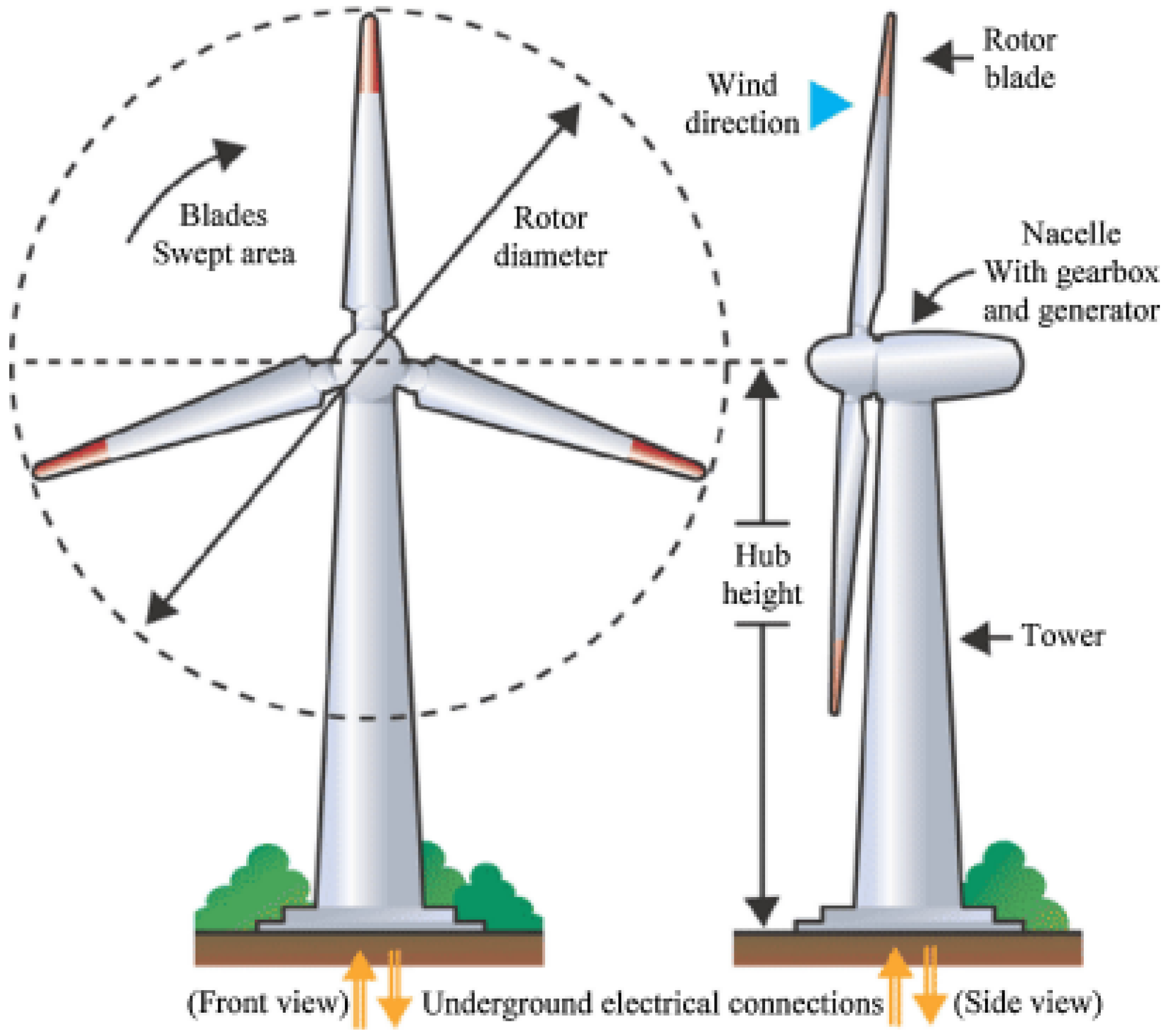
The wind is harvested through wind turbines, which generate electricity by rotating the blades attached to the rotor, which is attached to the nacelle at the top of the tower, as shown in
Figure 1.
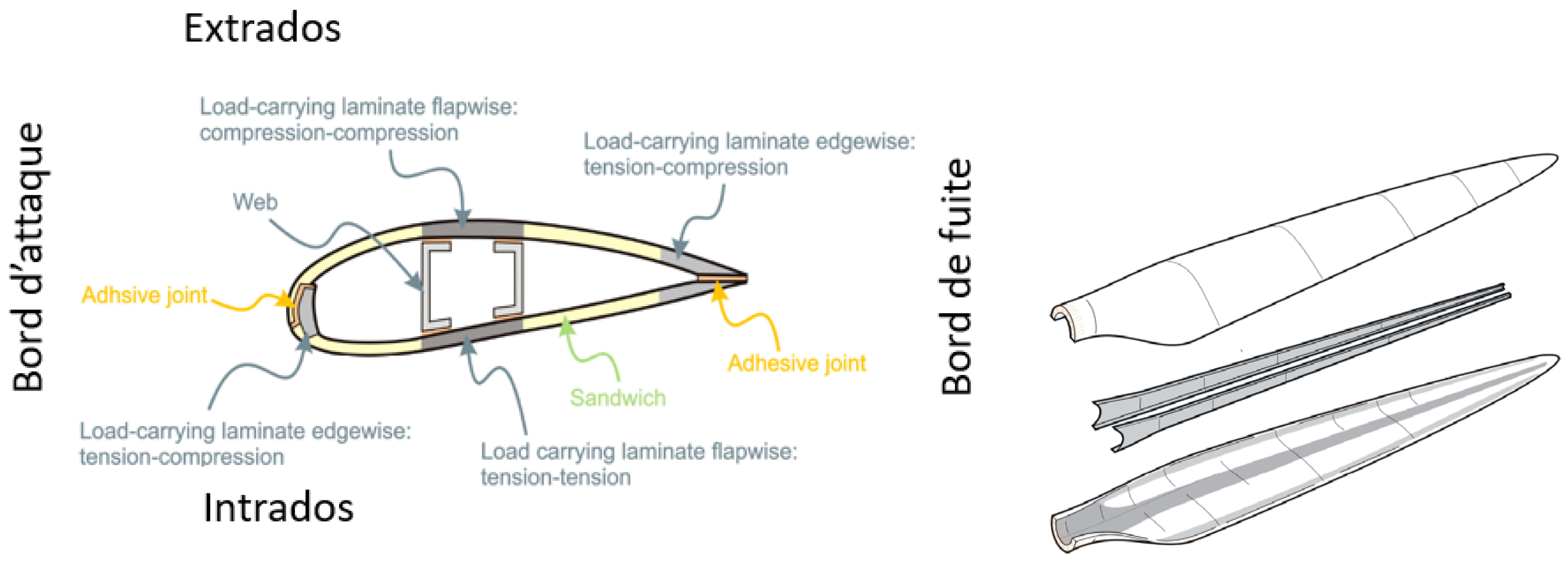
A wind turbine blade is made of two parts, the lower and upper surface, which are connected and stiffened with one or more shear webs that connect the upper and lower parts of the blade shell [
15], as shown in
Figure 2. This figure illustrates the cross-section of a WTB: the leading edge, the trailing edge, and the lower and upper surface.
In terms of loading configuration, one of the main laminates of the main spar undergoes cyclic tension–tension loads while the other experiences cyclic compression–compression loads. The leading and trailing edges that carry the bending moments associated with the gravity loads undergo tension–compression loads [
17]. The flap load is caused by wind pressure, and the edge load is due to gravitational forces and torque load.
3.1. Manufacturing of Wind Turbine Blades
Wind turbine blades are manufactured with composites using a process that is still very manual, leading to different types of defects. Hence, non-destructive testing is required to provide information on the surface and sub-surface of the blade while demonstrating the ability to inspect the blade from the surface [
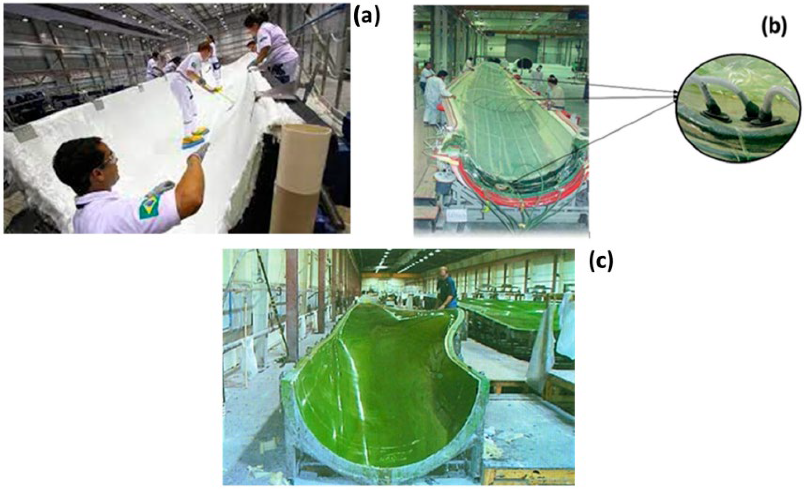
18]. Early types of WTBs were manufactured by wet hand lay-up technology (
Figure 3a). Fiberglass was impregnated with rollers and brushes. After being joined by adhesive, the shells are connected to the stringers. The cloths for the larger blades are sandwiched using the same approach but with a higher plies’ fiber content. As shown in
Figure 3b, product quality improved with vacuum infusion and the prepreg approach. The prepreg technology was developed by aerospace productions, using impregnated composite fibers. Resin infusion technology was adopted for large turbine blades by positioning the fibers in a closed mold; then, the resin is pumped into the mold. Heat is also applied for curing as soon as the resin settles on the fibers. This technique can be classified as resin transfer molding and vacuum-assisted transfer molding (
Figure 3c) [
19].
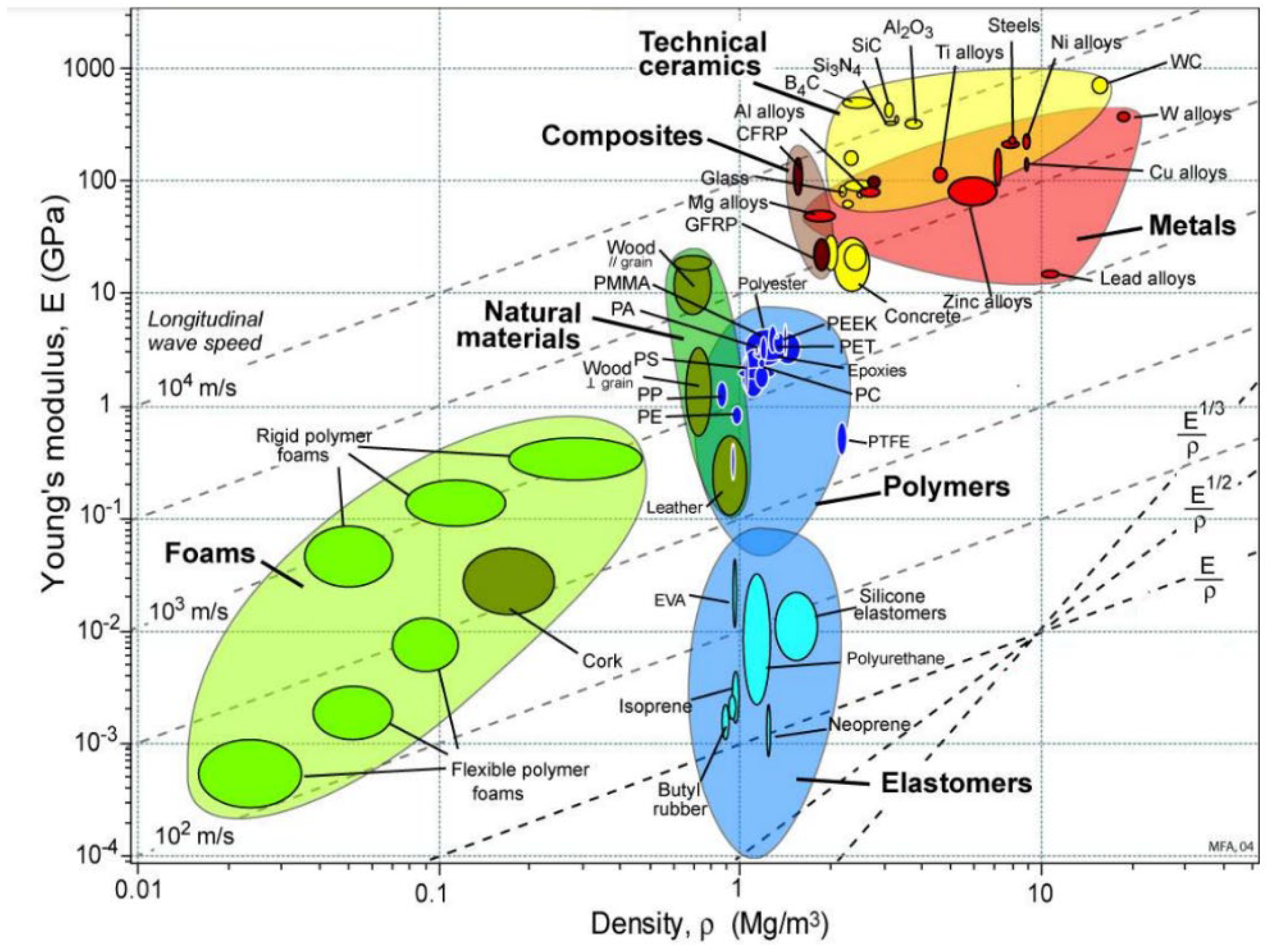
Various materials are used to manufacture WTBs, but the applicability of these materials depends on their weight and stiffness. As shown in
Figure 4, composite fibers have adequate strength and stiffness. Despite their high strength and stiffness, composites are lightweight in essence. The fiber orientation in a laminate governs the characteristic behavior of the composite. Therefore, composite materials are usually the preferred choice of material for the manufacturing of WTBs [
19]. Furthermore, experimental studies demonstrate that a low temperature increases the stiffness and compressive strength of CF/CPTSP. Conversely, higher temperatures may cause diminishing mechanical properties in composites [
20].
3.2. Damages in Wind Turbine Blades
The defects encountered on a wind turbine blade can originate from the design, manufacturing, handling, operation, or repair. A defect might also have been created for multiple other reasons [
21,
22,
23]. Poor design, i.e., underestimation of loads and poor defect characterization, can lead to damage during operation or handling (during transport of the blade). The manufacturing process of WTBs is not very automated and, despite the rigor applied in the quality control, some defects on the blades can escape the intiail inspections in a factory. In this case, a dry fiber or a ratio rich in fiber can lead to local delamination. While handling the blades either during transportation (often over long distances) or during installation by crane, the blades can be subjected to shocks or compressions, causing scratches, and chipping (on the leading or trailing edge). Once in operation, the blade is subjected to multiple potential causes of wear or failure, including leading edge erosion, lightning strikes, frost, particles from agricultural land, ultraviolet radiation, salt air, birds, and insects. Poorly executed repairs can lead to new defects or more severe damage.
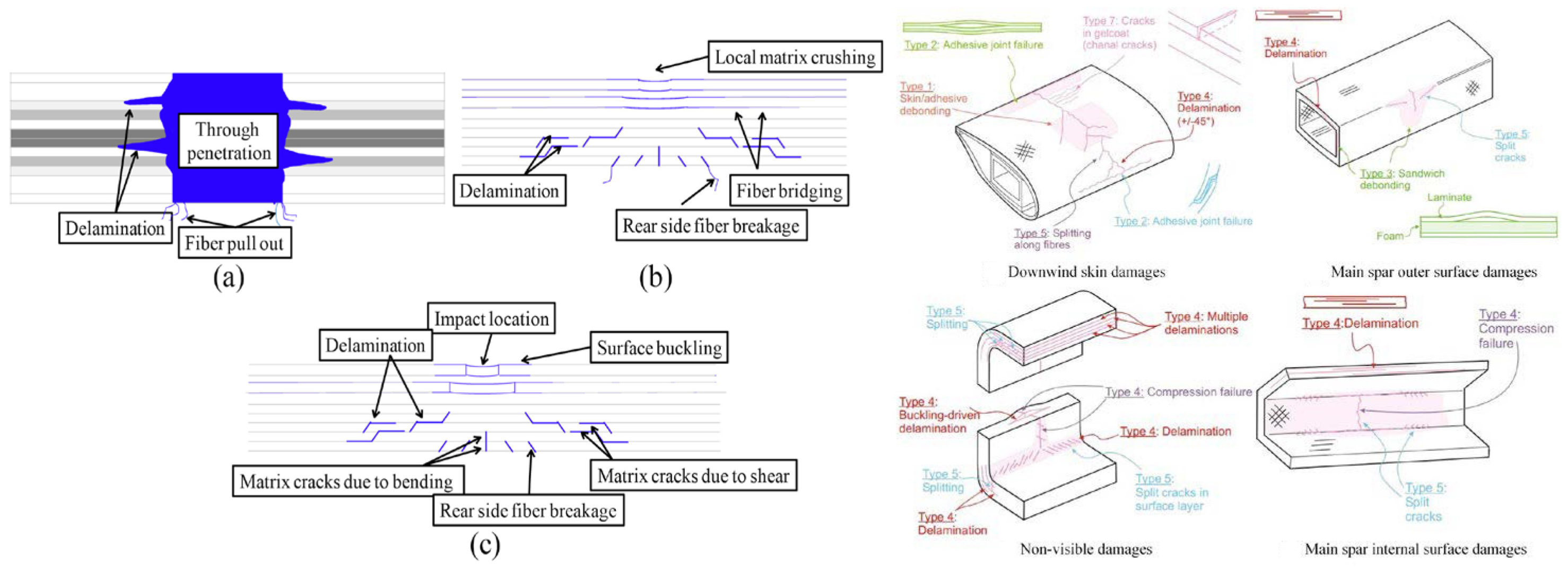
As explained earlier, a good understanding of the causes of deterioration of composite WTBs is crucial to the life of the blades. This is of great significance, since the blades are subjected to different loadings. Defects in composite materials ending in the deterioration of composites have been extensively studied.
Figure 5 presents significant information on the different deterioration mechanisms resulting from the action of loads.
As the material properties are not constant in all directions for composite materials, the mechanisms of deterioration are more complicated. Furthermore, when subjected to transient loading, the resulting stresses are not uniformly distributed over the material. That is not the case for metals, as they are inherently ductile and preserve their toughness even during deformation. Composites, however, are brittle and particularly vulnerable to damage as they are subjected to variable loading. As composites are subjected to variable loading, the matrix is most susceptible to shear cracking. Flexural cracking is likely to occuras the lower part of the composite is subjected to bending load. There is also a possibility of delamination (
Figure 6) as the cracks are confined. The fiber also could be damaged by tension, in addition to buckling, when subjected to compressive stresses. Two principal damage modes that often occur in low-energy impact conditions are resin cracking and matrix interfacial deterioration. Fiber failure is the dominant failure mechanism in high-energy impact conditions. The fracture toughness is, however, inferior to brittle resin systems. Here are some examples of the most common defects found on wind turbine blades. It should be noted that these are surface defects [
20,
21,
22,
23,
24,
25,
26,
27,
28]:
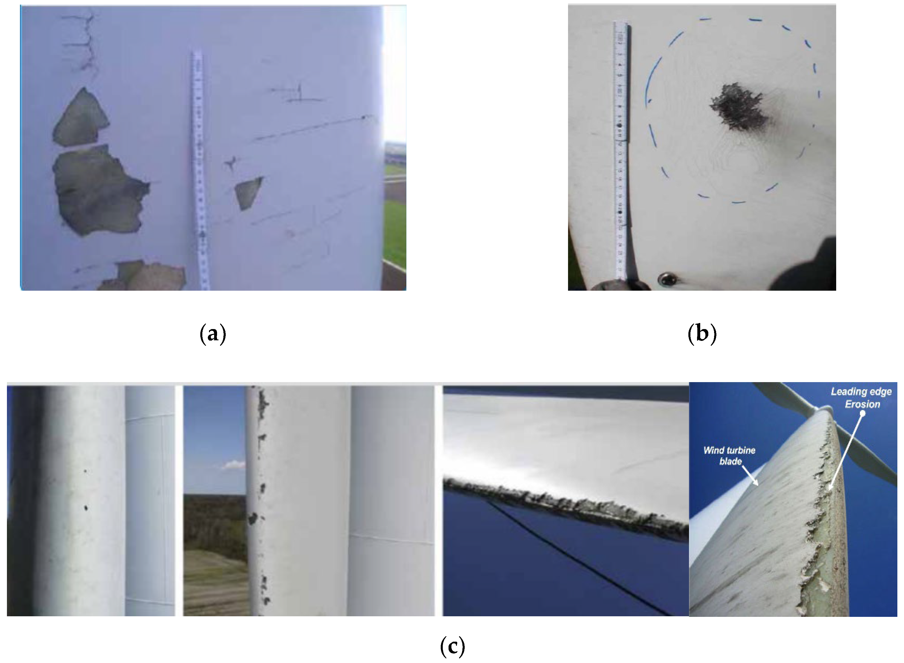
Erosion: Wear caused by high-speed collisions between airborne particles and the blade (hailstones, water droplets, sand, insects). Leading edge erosion due to impact fatigue is a serious issue for wind turbine blades, which might be caused by a variety of factors, including collision with rain droplets, hail stones, and other airborne particles. Repeated impacts to the leading edge cause an accumulation of damage and, eventually, cracking of the tip of the material;
Dry fiber: An area in the laminate where there is no resin, resulting in a different coloration. The stack of compressed dry laminate experiences the full pressure of the atmosphere—just like the open top of the resin pot, which is about to infuse. The infusion process is such that the atmosphere acts almost like a piston on the resin pot, pushing it down, then through the hose into the low-pressure area inside the bag. This is like pushing down on the plunger of a syringe and injecting the resin into the part just the plunger is the atmospheric pressure;
Delamination: Separation of the laminate layers due to poor infusion at the mill, regarded as one of the most common forms of failure of composite materials. Due to imperfections initiated by the manufacturing process or external factors during the lifetime of composite laminates, i.e., foreign body impact, the phenomenon of delamination can occur;
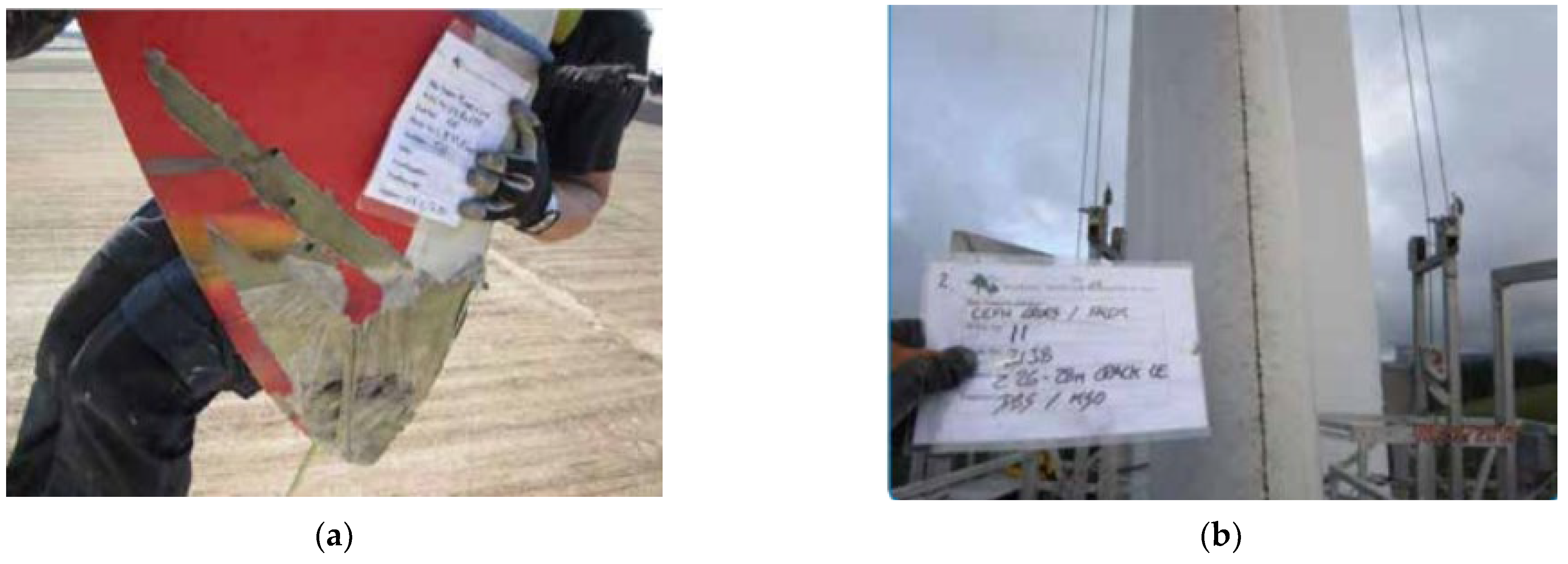
Cracks: Breakage of the laminate or glue joint. Even if it seems harmless, a crack should never be overlooked, since it may be larger in size and may propagate (
Figure 7). Mmechanical fasteners (such as clips, screws, etc.) can be used to join composites or mixed materials, but they require additional steps to mold or create features for the fastener. These additional features eventuate in stress concentrations and non-uniform stress distribution, which can result in cracking and failure;
Cracking: Grouping of several cracks located at the root of the blade and along the leading edge and surfaces, opposite the spars;
Microcracks: Cracks (or spalling
Figure 6 and
Figure 7) are often thinner than the gelcoat caused by poor infusion at the factory. They are difficult to detect, and their observation depends on the inspector’s perception. In the case of hardening as a consequence of microcracking, the relative displacement of the microcrack faces over loading and unloading cycles causes them to grow;
Blistering: Poor adhesion of the gelcoat to the laminate, causing local delamination of the coating. Adhesion failure happens when the adhesive fails to attach firmly to the substrate, which can be perceived as it is separated cleanly from the surface. It should be noted that adhesion occurs in very delicate regions of the surface;
Deep cavity: A cavity that reaches one or more layers from the surface;
Scratches: Damage, superficial or not, to the surface of the blade;
Pitting: Cavities of less than one millimeter, produced by poorly executed or controlled application of the gelcoat;
Spalling: Partial (flaking) or complete (exposed laminate) disbondment of the gelcoat.
3.3. Damage and Defect Categorization in Wind Turbine Blades
The assessment of detected wind turbine blade damage usually involves determining its severity and/or criticality. This process helps to categorize observed wind turbine blade damages into common severity categories. The categorization of damage and defects in wind turbine blades is a challenging task that lacks guidance in the form of an industry standard. However, categorization enables decisions on the maintenance actions, execution, and timing of repairs, considering practical and commercial concerns such as season, accessibility, the impact of downtime, and the availability of crews and materials. To assess the damages and defects of different blades, categories 1–5 are presented as potential answers. Categories 1 and 2 are considered for minor damage or defect, categories 3 and 4 for moderate damage or defect, and category 5 for major damage or defect. In some cases where multiple defects are present, lower-category defects may be grouped to form higher-category defects. Further, it may be cost-efficient to monitor several lower-category defects as single, higher-category defects. Recategorization is generally needed for lower category damage and defects [
32].
Category 1–3 damage or defects can often be operated with inspections every 6–12 months. Category 3 or 4 damage or defect should be repaired or shut down within 6–12 months, with at least an inspection every 6 months. Category 4 or 5 damage or defect should be repaired or shut down within 1–12 months, with monthly monitoring. Only the most severe damage and defects are considered serious enough to stop the turbine until it can be repaired. Moderate and less serious damage can be monitored once or twice a year with ongoing operation. For lower damage and defect categoriess, growth would need to be 100% or more before the action plan is reconsidered, whereas with damage or defects in categories 4 or 5, any (or a small amount of) growth would be cause for concern and re-evaluation.
Table 1 depicts photographic examples of damage and defects in each category.
3.4. Standards for Rotor Blades of Wind Turbines
Rotor blades should be designed so that the maintenance of normal operating conditions is ensured. The rotor blades should also reach the expected lifetime with sufficiently high reliability. In addition, the safety of personnel and installations must be ensured and risks of injury to human life must be reduced to a minimum. The rotor blade standards deliver an internationally acceptable level of safety by defining minimum requirements for wind turbine rotor blades (in combination with referenced standards, recommended practices, guidelines, etc.). These standards serve as a design basis for designers, suppliers, manufacturers, purchasers, and regulators to specify requirements for wind turbines subject to certification schemes. The design basis is sufficient for a safe design of the wind turbine rotor blade covering the scope of certification specified as part of the design basis. Design load assumptions that are used as a basis for the design verification of the blade structure should be specified as part of the design documentation. In case of changes in the design loads, a load comparison may be carried out to show that the blade continues to be compliant with the standard requirements.
The DNV GL standard, for instance, provides principles and technical requirements for rotor blades for wind turbines both onshore and offshore. This standard is, in principle, applicable to all types of wind turbines and rotor blades, even though many requirements have been formulated specifically for blades made from fiber-reinforced composites for operation on horizontal-axis wind turbines. The DNV GL standard can be applied as part of the technical basis for carrying out DNV-GL-type certification of wind turbines or DNV GL component certification of rotor blades. This standard is applicable to the structural and functional design and manufacturing of rotor blades for wind turbines, including requirements for materials, testing, repair, and operation [
33].
For all processes involving polymeric materials, the manufacturing processes to be applied in connection with each material should be reported in a generic process description. For fiber-reinforced composites, these should at least include:
Type of processing (hand lay-up, infusion, pultrusion, prepreg, or others);
Principle of vacuum set-up and level of applied differential pressure;
Most relevant processing temperature profiles, at least including application temperature and time, and cure temperature and time (or a definition of a minimum required degree of curing to be achieved by the curing process for each resin system);
Target fiber volume content.
For adhesive joints, these shall at least include:
Type of processing (co-curing, co-bonding, adhesive bonding, or others);
Maximum and minimum thickness of adhesive joint;
Most relevant surface preparation parameters (peel-ply, grinding, protection, open time);
Most relevant processing temperature profiles, at least including application temperature and time, and cure temperature and time (or a definition of a minimum required degree of curing to be achieved by the curing process for each resin system).
The manufacturer shall ensure that each rotor blade is produced in accordance with the specified materials and the design assumptions. The manufacturing of wind turbine blades shall be carried out according to appropriate documentation, at least including approved work instructions, drawings, and quality procedures. Such documents shall cover the scope of all relevant manufacturing processes. The manufacturer is responsible for ensuring that all tests and inspections are laid down in accordance with the standard, and that any standards, specifications and other applicable regulations are carried out. Quality control of fiber-reinforced composite production comprises control of the raw material, surveillance during production, and checking the quality of the finished components.
The operator of a wind turbine shall ensure that, as long as it is in operation, the installed rotor blades are inspected and maintained on a regular basis. Inspections and maintenance shall take place at regular time intervals and be based on the procedures specified by the original blade manufacturer (e.g., in manuals). The detailed technical scope of inspections and maintenance shall be specified by the original blade manufacturer as part of their documentation. These should at least include [
33]:
Outer surface quality;
Structural integrity of laminates, from the outer as well as the inner surface;
Adhesive joints at leading and trailing edge;
Adhesive joints on the inside (such as shear web joints);
Attached items (e.g., lightning protection);
Lightning events;
Corrosion and pre-tension of bolts;
Mechanisms or installed systems, if applicable.
The article detail the methods used to inspect the blade’s outer surface and sub-surface to ensure the maintenance and operation of the wind turbines in order to produce the estimated energy over the expected lifetime.
4. Inspection Methods of Wind Turbine Blades in Operation
The definition of inspection is to move a sensor (e.g., camera) to collect information over the entire surface. The purpose of an inspection is to detect defects. Leaving these defects can result in loss of efficiency and, in the worst case, the failure of the structure or component. In this study, we are talking about failure of the blade, which is the main component of the wind turbine. Without blades, the wind turbine would not be able to harness energy from the wind and, therefore, would not be able to generate electricity. The first inspection of WTBs is carried out after manufacturing and during quality control in the factory. Once the blades are in service and operation, this is called field inspection. The inspection methods used in the factory differ from those used in the field. In the factory, a full inspection can be performed, that is, on and under the surface of the blade, allowing for the detection of defects on the surface and in-depth. Conducing this form of inspection in the field is much more complicated. In the case of field inspection, the inspection is carried out to prevent major failures and ensure the aerodynamic performance of the blades. In addition, an inspection of blades ensures that the manufacturer’s warranty is honored. Once defects are detected by a camera or other methods, they must be located (park, turbine, blade, distance from root, GPS point) and categorized, either automatically, through image processing, or manually by a technician. Various geolocation methods, including laser rangefinders, sonar, and GPS-equipped drones are currently available on the market. Although there are several publications on the subject, automatic defect detection from blade images is still under development [
34].
Many of the currently available inspection methods can only be implemented in the factory. Moreover, among the few methods that are applicable to already-installed blades, some only allow for the surface to be evaluated (surface inspection), while others allow for the subsurface structure to be evaluated at greater or lesser depths (subsurface inspection). These methods are referred to as non-destructive methods [
34,
35]. In this article, surface inspection methods will be presented, followed by subsurface inspection methods. The use of sensors installed on the blade will also be presented, allowing for the prediction of failure in advance before it occurs; in other words, this method will be used to detect defects.
5. Surface Inspection
The inspection methods on the surface of the blades allow for the detection of external defects (cracks, erosion, lightning damage, disbonding of glue joint at the leading or trailing edge, etc.), but do not allow for the detection of internal defects, even in the case where some of these defects are manifested on the surface. The methods of inspection on the surface are as follows:
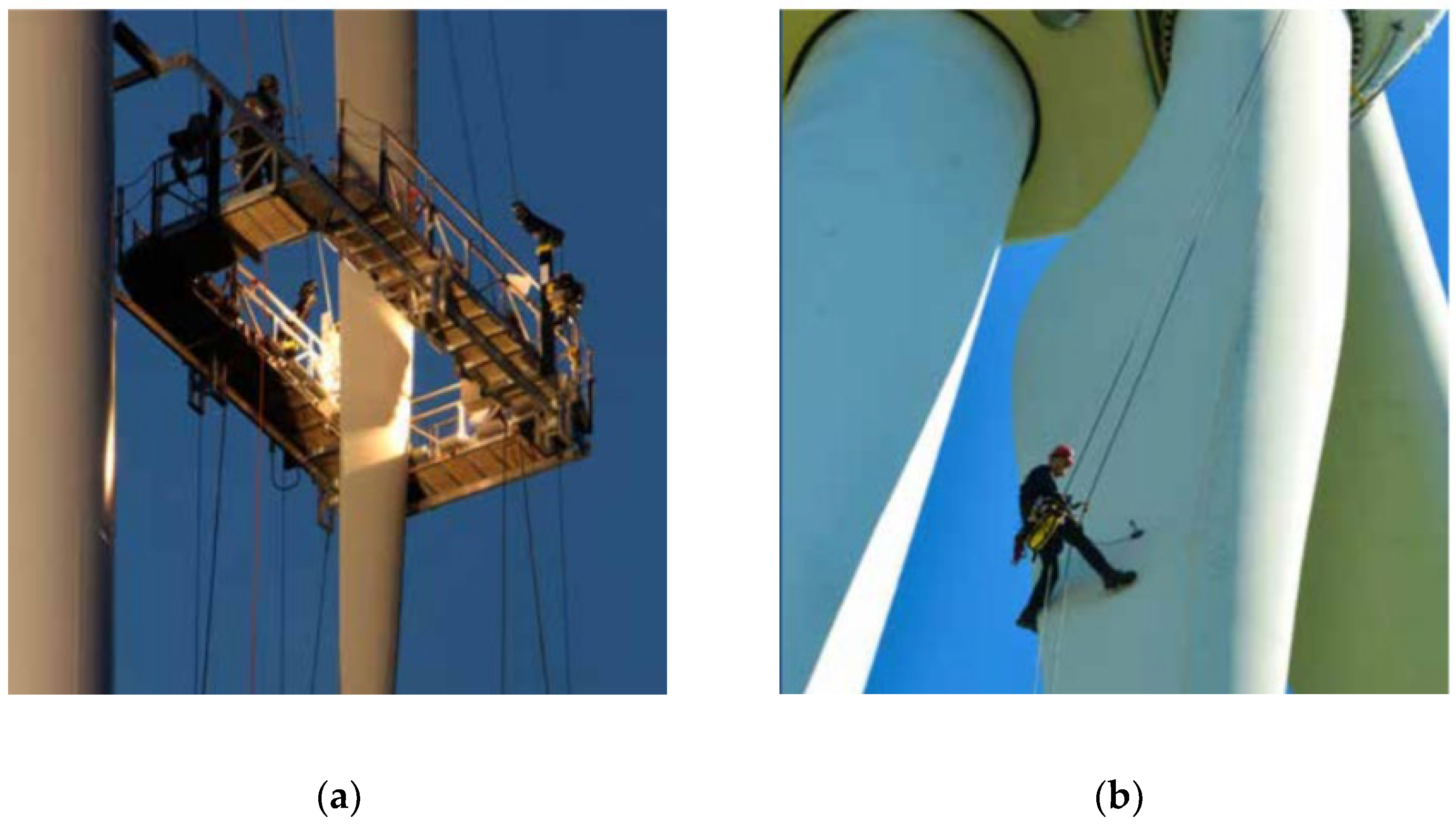
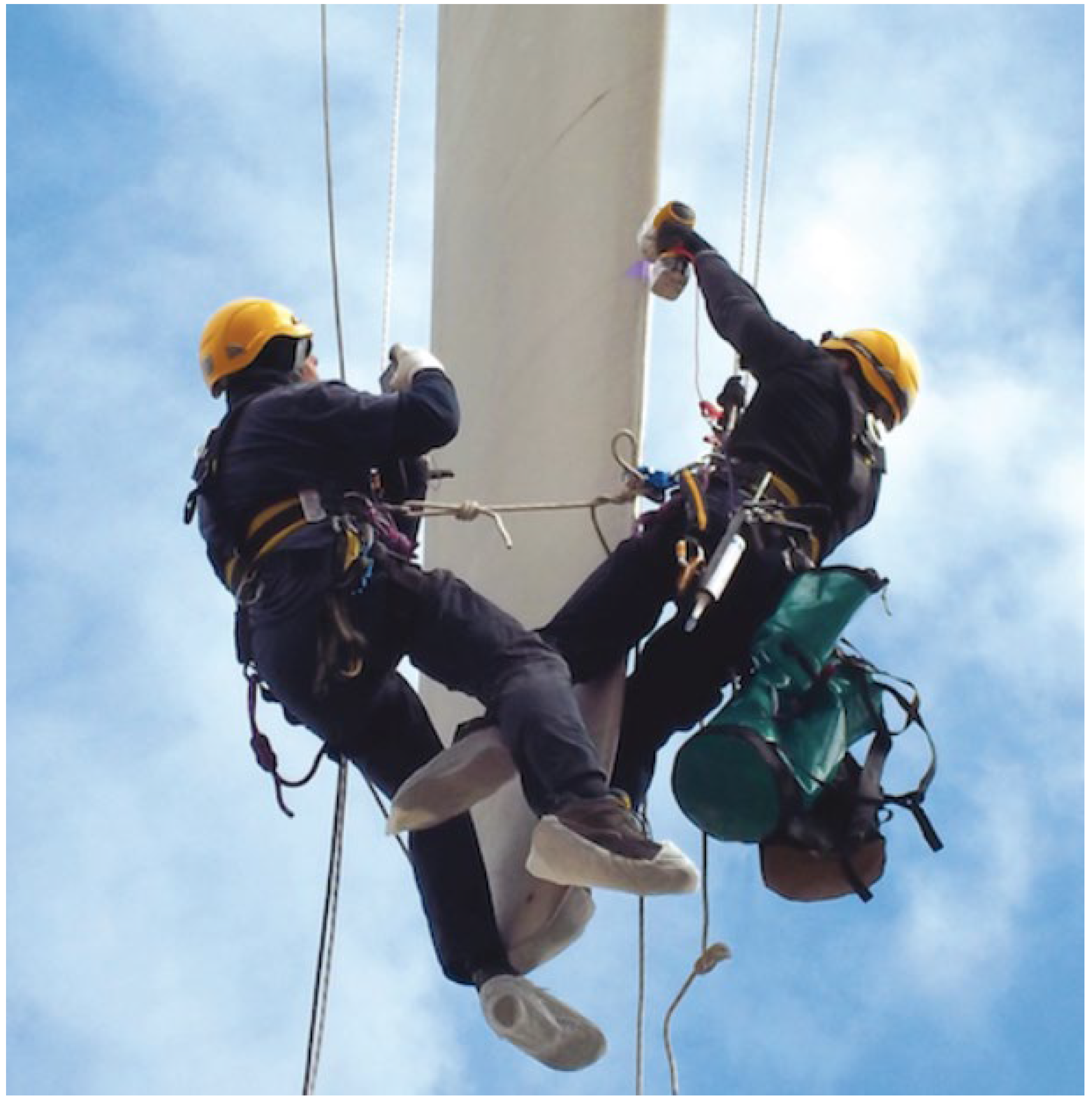
Visual inspection by a rope or platform worker (
Figure 9) is very time-consuming (requires several hours of inspection for each blade and the turbine is shut down the entire time); it is possible to repair the defect on-site, but it is expensive. Visual inspection from the ground is also very time-consuming. Visual inspection from a drone is very fast and safe for the worker. Although the various manual inspection methods that have been used to date are able to detect and characterize several defect categories on a blade, they remain time-consuming and expensive. Some of these methods, such as rope inspection, pose safety risks for workers. However, the use of remote inspection methods using drones, which are more flexible, faster, more economical, and safer, can limit the number of defects detected by inspection or affect their classification. Despite these constraints, drone inspection has undeniable advantages. Studies conducted with different industrial stakeholders have shown that the use of remote-inspection methods using drones has indeed the advantage of providing a quick and cost-effective idea of the number of defects and their distribution for a wind farm. Although the use of drones does not have the same accuracy, all agree that it allows for the inspection of a greater number of blades at the same time, limiting direct interventions to only those needed for repairs. In this respect, the use of drones could revolutionize field inspection.
5.1. Machine Vision
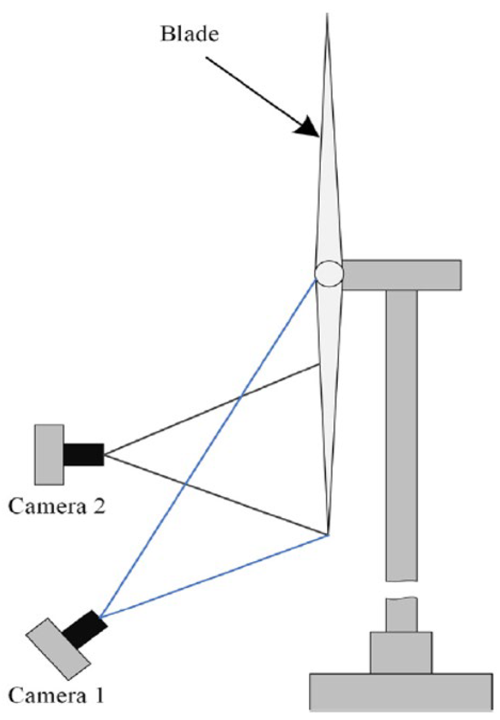
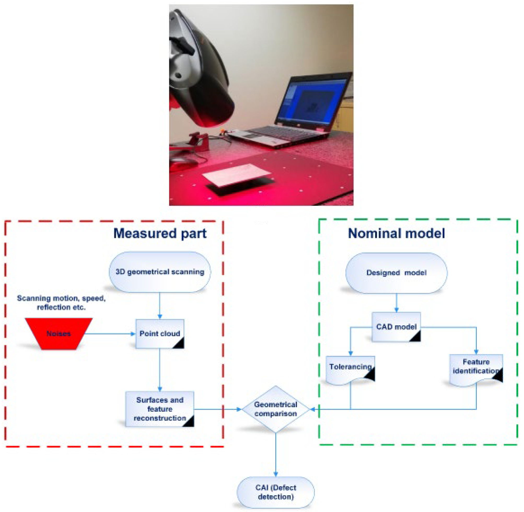
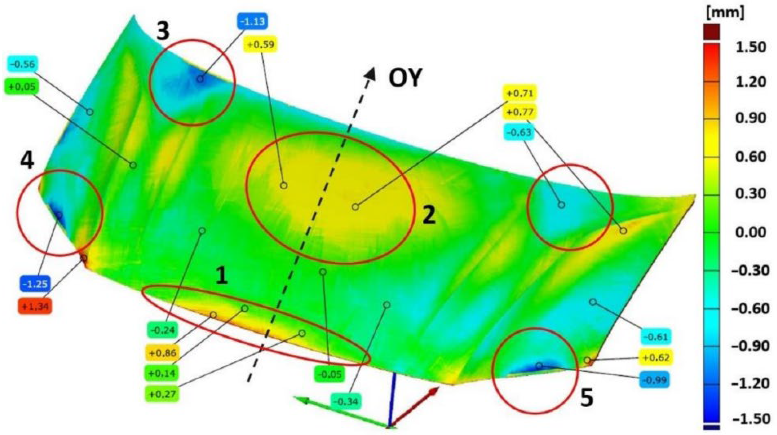
Computer vision-based detection methods use 2D/3D image sequences from different locations to capture object information, which is akin to the stereoscopic vision of humans. Computer vision-based detection technology delivers surface damage detection such as cracks, scratches, etc. A schematic of the computer vision-based detection technology is shown in
Figure 10. The figure illustrates the binocular vision detection method, which obtains information by acquiring images from different perspectives according to parallax principles. The detection steps include image acquisition, image processing, and damage identification. This method places great demands on imaging equipment and data processing, particularly for online monitoring. This technology can also lessen hazardous tasks being conducted at height in a wind farm by human workers [
37].
5.2. Inspection by Drone
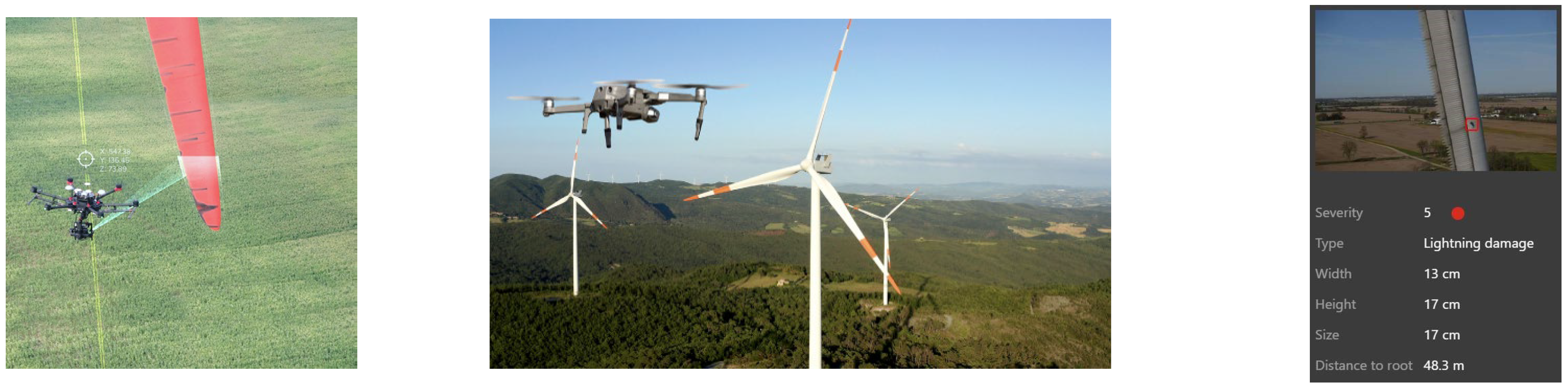
Inspection drones can be equipped with different kinds of sensors and cameras, such as RGB, IR, LIDAR, multi, and hyperspectral. Multiple sensors can even be integrated to develop multi-scale inspection systems, thereby reducing the number of flights required to complete a single job. Light detection and ranging (LIDAR) sensors use laser-emitted light energy to scan the blade and produce high-resolution 3D models of objects. Drone-based hyperspectral sensors collect data as a series of narrow and contiguous wavelength bands providing a high level of performance in spectral and radiometric accuracy. Drone inspections can also include damage review and access to cloud-based processing obtained by LIDAR sensors. There are only a few techniques that are capable of detecting sub-surface damages; even multi-spectral cameras can scan about a 2–3 cm sub-surface; this requires the drone to be relatively close (10–15 cm), which, from an operation point of view, can carry risks to the blades, the high-value assets.
Visual inspection by a drone can be used with or without automated image processing, and with or without automated defect detection. This inspection is also quick and safe, allowing for access to restricted areas (
Figure 11). Drones enable safe and efficient inspection to collect data for energy companies. Using drones for wind turbine inspections opens up new opportunities to replace existing inspections with shorter inspection times, lower labor costs, and fewer unsafe working hours, while providing high-quality data. Without drones, inspections are usually performed manually by climbing or using long-range photography. It is clear that the manual inspections associated with climbing carry risks that drones avoid. The collection of ground-based data can be slow and fails to provide detailed information compared to that which drones can capture. Due to their many advantages, the use of drones for turbine inspection is becoming more common. the inspection of the blade surfaces by a drone can be carried out in 15 min, i.e., 45 min for the 3 blades, plus 30 min to change the battery of the drone and to turn the rotor, to which 15 min must be added for the displacement between two wind turbines. Therefore, a full inspection of the blades of a wind turbine can be completed in 1 h30 under good conditions. In general, the following benefits can be achieved using drone inspection [
38]:
5.3. Offshore Wind Turbines Inspection
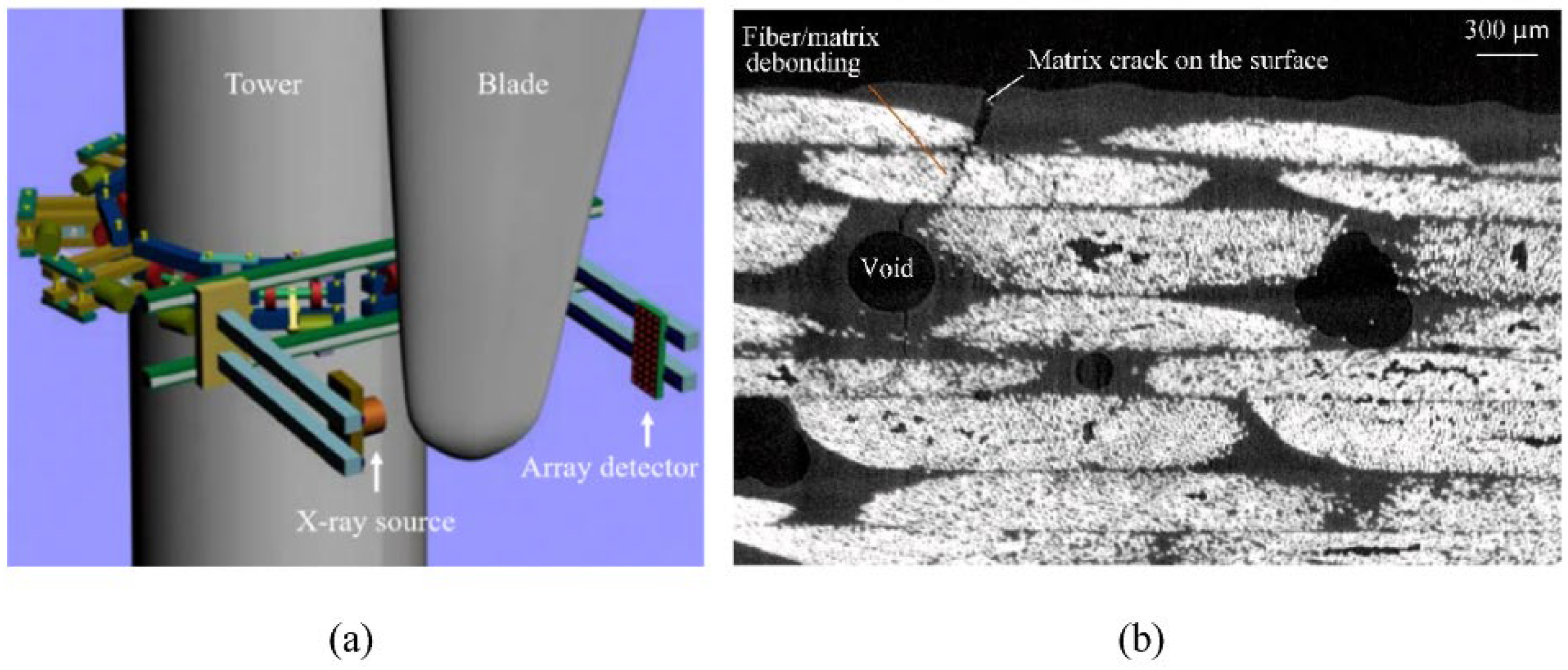
Remote geographical locations and the positioning of critical parts of a WT, for example, its nacelle and blades, make it unique and challenging for servicing and maintenance, especially offshore sites for transporting wind farm technicians and other personnel by Crew Transfer Vessels (CTVs). The environment inside the nacelle of the offshore WTs is different from that of the onshore WTs. The ambient temperature inside the onshore WT nacelle, operating, for example, in the Saharan climate, can be in a wide range from −40 °C to +55 °C. This could be problematic when selecting the materials, for example, when finding electronic equipment that can operate in such a range. The condition could be worsened for the offshore WTs because of the need for an air-tight nacelle unit to minimize the inflow of corrosive outer air and other corrosive marine elements (e.g., salt spray or fog). This could lead to an increase in the internal temperature inside the nacelle, such as in the generator part, which could go up to 150 °C when the cooling system is not adequately installed. The remote location and position of offshore wind turbine structures severely limits the application of in situ corrosion detection methods such as ultrasonic, acoustic emission, and X-ray. This leads to the requirement of technology development for a cost-effective end-to-end nondestructive testing (NDT) corrosion detection and monitoring solution for offshore WTs. This can be achieved through the implementation of real-time remote sensing (RTRS) technology utilizing electrochemical sensors, as there are limitations with the use of in situ techniques, such as ultrasonic, acoustic emission, and X-ray with regard to access for operators and the power source. The electrochemical sensors could instead be used to remotely monitor the physical and electrochemical changes that take place on the metallic materials [
39].
7. Using Sensors to Detect Wind Turbine Blade Defects
Sensors installed on the blade or rotor shaft can be utilized as an inspection instrument to detect defects in the operating WTBs. The collected data can help to diagnose the presence of defects in the blade and plan repairs. The advantage of this method is that the data can be visualized live and the emerging defect/failure can be known in advance. The disadvantage of this method is that the damaged areas cannot be precisely located and the sensors are exposed to environmental conditions, including an extremely cold temperature, icing, and lightning, and these sensors can also be damaged in time or sometimes provide biased information due to icing phenomena.
These sensors include, among others, strain gauges and accelerometer. Strain gauges are used to measure deformations at specific locations, while accelerometers are used to measure the dynamic response and to perform modal analysis of a blade. However, there are some challenges in the use of on-blade sensors, including:
Sensor installation during manufacturing or after commissioning;
Reliability of the sensors, which must be maintained for approximately 20 years;
Robustness of the communication, storage, processing, and data analysis systems.
7.1. Vibration Analysis
Vibration analysis is a viable technique to maintain consistent operation, particularly for rotating equipment. The sensor type is fairly dependent on the frequency range (0.01–100 kHz): low-frequency range for position transducers, the medium frequency for velocity sensors, high frequency for accelerometers, and very high frequency for emitted spectral energy sensors. The physical condition of materials is monitored for the detection and growth of cracks. Common methods are generally offline and are not appropriate for online condition-monitoring. Exceptions can be made for the use of optical fuses in blades and the acoustic monitoring of structures. Strain gauges could be an option for condition monitoring, but are not sustainable for long-term monitoring. Strain measurements could be beneficial to predict the lifespan and stress level backup, especially for blades. Fiber-optic sensors are promising in this regard, but still very expensive (
Figure 18).
7.2. Acoustic Emission
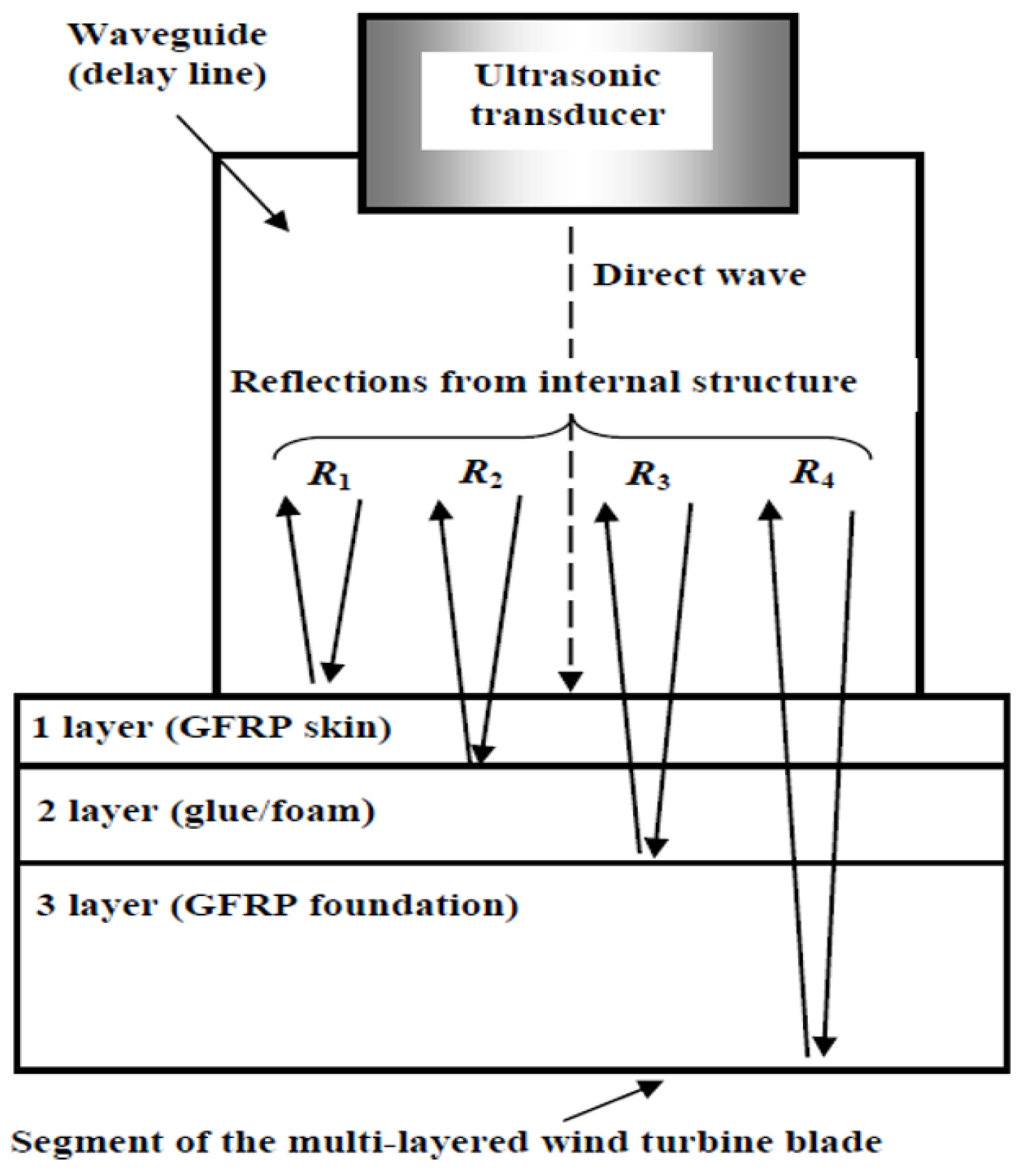
The acoustic emission technique is suitable for the detection of the probable failure of a blade in real-time or certification tests. Elastic waves generated by rapid energy release from localized sources in a multilayer structure of the blade are used to identify damages (
Figure 19) [
41,
42,
43,
44,
45]. Acoustic monitoring is closely related to vibration monitoring. However, vibration sensors must be rigidly mounted on an object to record the local motion, and acoustic sensors are used to record the response of an object. They are attached by a flexible, low-attenuation adhesive. There are two acoustic monitoring techniques: the passive type and the active type. In the passive type, the excitation is performed by the component itself. In the active type, the excitation is applied by an external source [
41]. When testing a fiberglass structure using acoustic emissions, the emission source is the cracking of the matrix and fibers. The dominant emission mechanism is determined by the material characteristics and stress field that are locally applied to each material region. Recording acoustic emissions in a fiberglass structure that is subjected to external loading signalizes a localized failure in the part. However, during initial loading or at low loads relative to normal loading, the fiberglass structure generates acoustic emissions. In these emissions, informative signals from internal cracks and non-homogeneities are present, but this effect can be used to locate regions with high residual stresses. In a large fiberglass structure, the optimal application of acoustic emission entails the spatial localization of the acoustic emission sources. There are, however, problems with localizing an acoustic source in a glass fiber with a complex structure, such as the high acoustic attenuation and phase velocity dispersion.
9. Industry 4.0 for Wind-Power Industry
9.1. Sustainable Energy Production
The goal of sustainable energy development is to create resilient infrastructure and promote inclusive and sustainable industrialization, as well as foster innovation. Access to affordable, reliable, sustainable, and modern energy requires a significant increase in the share of renewable energy in the global energy mix, as well as a doubling of the global rate of energy-efficiency improvements. In this regard, energy production from wind farms is the technology with the lowest cost of electricity production among renewable energy sources. When operating a wind farm, it is important to avoid unplanned outages because, in addition to the repair costs, operators lose revenue while the turbines are down.
Therefore, predictive maintenance should use extensive data to create a database regarding the turbine and its environmental conditions to detect anomalies in operation and early failures. In this way, the risk of failure can be reduced, and operations can be efficicently managed. Integrating condition monitoring systems (CMS) and new methods for data processing should be created by exploiting the benefits of new technological developments in the energy sector, as well as in the area of information and communication technologies. Industry 4.0 technologies can help to provide solutions for both communications in wind turbines and networking in a wind farm.
9.2. Industry 4.0 Technologies
Industry 4.0 refers to cyber-physical technologies for the interconnectivity of technological developments to improve and optimize industries, businesses, and related processes [
48]. Industry 4.0 could contribute to finding new ways of dealing with some of the major global challenges, such as climate change, food insecurity, lack of energy access, and water scarcity. The revolutionized wind-energy industry requires the application of Industry 4.0 technologies such as smart manufacturing, the internet of things (IoT), smart inspection, and digital twins (DT). Dealing with data is the key to success in almost every industry. Digitization projects, Industry 4.0 implementation, or artificial intelligence applications are all data-driven. The digital infrastructure for autonomous and highly dynamic data value creation networks thrives only because of the participation and use of data.
9.3. Combining Industry 4.0 and Wind-Power Industry
Sustainable wind energy and Industry 4.0 share important characteristics that can be interconnected to pursue digitalized wind-energy production. The wind-power industry can be informed by a vision where the physical world of energy production merges with the digital world of information technology; in other words, the creation of a digitized and interconnected energy production system. Numerous opportunities, with high economic and energy-saving potentials, are associated with digitalized and interconnected wind-power energy.
One of the biggest challenges often expressed by companies related to Industry 4.0 is data security. Standardized and secure data exchange for data value creation is the basis for new cooperation and collaborative data-usage concepts. A less prominent challenge is protecting and ensuring the privacy of employees, who also contribute a great deal of personal information when constantly interacting with constantly connected devices. In this context, the goal is to build virtual data rooms that are more efficient, open, and flexible in their use of data, without neglecting data ownership and, at the same time, guaranteeing data sovereignty. Virtual data spaces can be created for inter-company collaboration and standardized data trading. The focus of this pre-commercial project is to develop a scalable and secure architecture for such a data room using modern information and communication technologies. Regulatory policies are useful to define contracts associated with the data. These contracts are based on rules for usage-tracking, such as the duration of usage, data sharing, etc. In addition, the purpose and cost of data use can be specified. For instance, sensitive data can be made available for calculations with the certainty that it cannot be read or used in any other way [
52].
Digital twins are a virtual representation of a physical system that functions as a real-time virtual model of the physical system. The digital twin tracks the whole life-cycle of a wind turbine from manufacturing operation and maintenance. Digital twins consist of three main components, the physical system, digital system, and networking platform, which initiate communication between different elements of physical and digital systems. A variety of enabling technologies should be implemented, as demonstrated in
Figure 20, to encompass the comprehensive elements required for DT. This DT model is particularly suitable for health-condition monitoring of complex equipment in varied engineering fields, e.g., in tunneling and underground space engineering, marine engineering, and wind engineering [
53].
Since massive multisource heterogeneous data are generated during the operation of a wind turbine, big data analytics technologies are required to collect, transmit, store and process the data. DT services cope with the concrete functions depending on the operation of the wind turbine. Extensive sensor technology is installed on the wind turbines to control and monitor their operation. In offshore wind farms, several hundred sensors continuously provide data on temperatures, pressures, speeds, accelerations, forces, voltages, environmental conditions, and other physical data. The issue of real-time data-processing and dealing with a large amount of available data may arise for digital twins of wind turbines. The adoption of IoT offers the significant benefits of DT—the ability for devices to communicate across a common platform. As connected machines can capture and document significant amounts of data, this allows for the opportunity to perform deep analyses across multiple devices. Issues and trends can be quickly identified and managed in a much more meaningful and efficient manner. Digital twins of wind turbines can not only follow the current condition, but also predict the future of their physical counterparts and play an increasingly significant role in proactive maintenance and prediction [
54]. In such a model, the simulated data obtained from numerical modeling and the sensor data acquired from the wind turbine are continuously monitored, collected, and processed in real-time to adapt to operational situations [
55,
56,
57]. The processed data from all these resources can be converted into the most effective and suitable operation-management and energy-production instructions.
Fog computing has been proposed to support IoT devices. This kind of computing architecture focuses on processing as much as possible before sending it to the data center. As a result, it is possible to process extremely large datasets by offloading the heavy work from the central server to the fog nodes.
9.4. Architecture of Wind Turbine Digital Twins
Digital twins’ software has been developed to make the most of the potential of digitization and big data to improve efficiency and reduce costs. Digitization is implemented using sensors embedded in wind turbines, and an ever-increasing amount of data are collected for analysis to monitor the components’ condition. Predictive maintenance and improved wind farm design are just two of the benefits that digitalization offers. Predictive maintenance, as a data-based service, is particularly relevant for wind-farm operators and their service providers. The object of this approach is to reduce unplanned downtime and optimize maintenance activities. The starting point is anomaly detection software, which is trained to recognize normal behavior in SCADA- and CMS-integrated data of a wind turbine using machine learning techniques based on a learning database. Situations with large deviations from normal behavior can then be identified as potential fault patterns. The trained AI can evaluate the data of a wind turbine and infer the fault-causing component through correction calculations. With more, better-quality data to consider, the AI delivers better results. When analyzing possible input data, such as loading, vibration/frequency and damage classification, different data sources (blades, nacelle, or foundations) need to be taken into consideration. In addition to the operating data of the wind turbines, additional sensor technology often provides relevant information. External data, such as weather data, must also be taken into account. For example, wind turbine manufacturers could use simulation models to predict the conditions of turbine and components, or predict service life based on detected anomalies [
58].
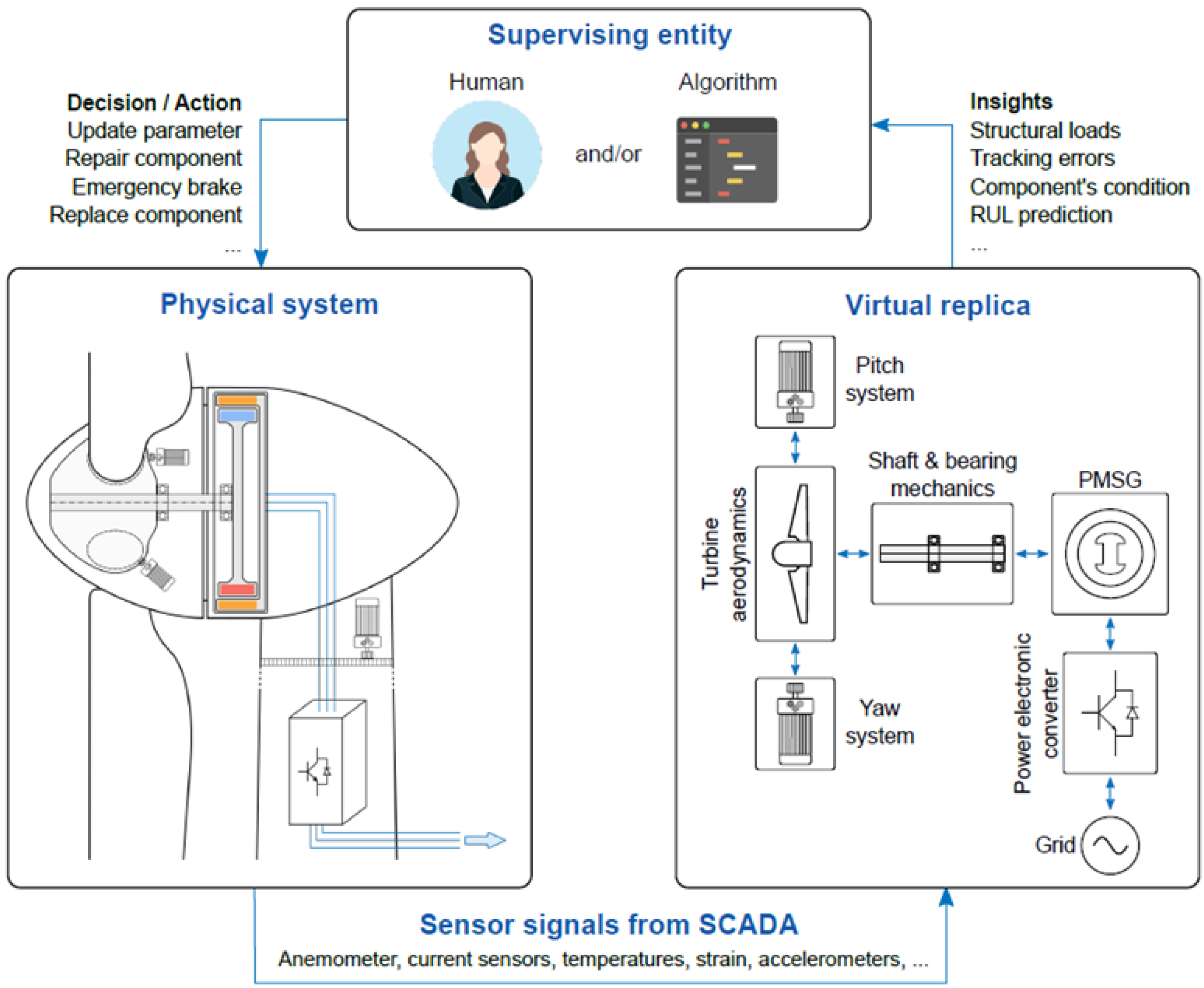
An architectural diagram of a digital twin for a wind turbine is presented in
Figure 19. Using a bidirectional information flow, the physical system communicates with the virtual replica. SCADA system transmits sensor signals to the virtual system from the physical system at the bottom. To ensure that the virtual replica accurately reflects the behavior of the physical system; these signals are fed into the sub-models. Supervisory entities receive insights from the virtual replica, which might be a human operator, a control engineer, a designer, or an automated algorithm. For example, the structural loads of mechanical components, control tracking errors, and operational parameters (temperatures, stresses, and remaining useful life (RUL)) can be included in these insights. Regulatory bodies can use these insights for decision-making regarding the physical system. For example, updating a parameter, repairing, or replacing a component, or even triggering an emergency brake. Multiple methods can be used to obtain insights from measurements or simulations. Applying these techniques to the virtual replica offered here might result in a digital twin for condition-monitoring and fault diagnosis. Realism is also influenced by the availability of qualitative data, as well as accurate models.
Current wind turbines are well-equipped with multiple sensors, which are linked to the SCADA system. The numerical power, rotor speed, and pitch curves can be superimposed with the data recorded by SCADA system [
59]. Meteorological data are collected by sensors on top of the nacelle. Wind speed and direction are measured with an anemometer and a wind vane, respectively. A secondary wind-speed and wind-direction sensor are generally included for both measurements. The LIDAR system, instead of the aforementioned sensors, can accurately determine wind speed. For example, LIDAR can provide a preview of upcoming wind, which is valuable for controlling loads, yaw, etc. The nacelle can also measure temperature and air pressure, in addition to wind speed and direction, to approximate the air density. Moreover, turbine blades can be fitted with accelerometers, strain gauges, and micro-electromechanical (MEM) sensors to measure structural loads and predict the behavior of flexible blades. Blades can also be equipped with temperature and humidity sensors to predict ice formation. Strain gauges, accelerometers, and vibration sensors are installed on the main shaft of the turbine. A vibration sensor, microphone, or eddy current sensor measures the thickness of the oil film on the bearings, as mentioned earlier. To monitor the stator winding temperature, the PMSG has a position sensor on the shaft, e.g., an encoder or a resolver, and a resistive temperature sensor Pt-100 or Pt-1000. Rogowski coils or current transformers can be used to monitor stator currents. Finally, the power electronic converter has sensors for current, voltage, and temperature [
60,
61,
62,
63] (
Figure 21).
10. Conclusions
Wind turbine blade inspection is performed in two stages, during manufacturing and over operational lifespan on-site. During manufacturing, full surface and sub-surface inspections can be performed by almost all the non-destructive testing techniques. Several techniques can be used for in-service wind turbine inspections, depending on the circumstances, such as visual inspections, ultrasonic, shearography, thermography, and X-ray CT. The drone inspection method stands out as the safest solution for inspecting the blades of wind turbines that are in service, as it can be equipped with different kinds of sensors, cameras, and LIDAR, providing the opportunity to merge and aggregate data from different sources using sensor-fusion techniques. Inspection by drone is a developing technology that generates large amounts of data from different resources. Using sensor fusion techniques for smart inspection in the framework of the Industry 4.0 system accurately delivers insights regarding critical components of wind turbine blades.
At present, the methods of inspecting wind turbine blades are updated based on data organizing, processing, and analysis. Efforts have been made to reduce the human impact on inspection and adapt them to data science. Data-based inspection enables predictive maintenance and, consequently, smart inspection. The collected data and simulation data provide an opportunity to create wind turbines as digital twins. Artificial intelligence and machine learning techniques can be employed to simulate the response of wind turbines for analysis by the digital twin in normal and extreme conditions. Digital twins can be virtually tested to analyze and evaluate wind turbines under extremely difficult operational conditions. The aspects of defect elimination and corrective measures related to each inspection method can be studied in future research works.

 ,
, 


