1. Introduction
Edge control and stability of a snowboard are among the most important key performance parameters of freeride boards, in addition to maneuverability and accuracy [
1]. It is evident that edge control and stability are not that important in freestyle boards, as a good edge grip is required only in racing conditions.
The terms edge control and stability of a snowboard refer to the ‘
level of grip exhibited during turns’ [
1]. Specifically, edge control is related to the ability of a snowboard to closely follow the arc of a carving turn, that is, the ability of maintaining the integrity of the carve. Poor edge control causes the board’s shovel to break out of the carve. The property responsible for poor edge control and stability at high speed is a ‘
highly active torsion mode’ [
2]. The magnitude of bending and torsional natural frequencies is directly related to ‘
snowboard controllability and handling’ [
3].
According to a Quality Function Deployment (QFD) analysis [
1], the subjective (rider) parameters, such as ‘
edge grip’ and ‘
stability’, correlate highly with the following objective design parameters of a freeride board:
- -
edge grip correlates with: board length, sidecut radius, torsional stiffness of the board’s body, edge sharpness and material [
1];
- -
stability correlates with: board length and width, sidecut radius, bending stiffness of the board’s body, body core material, and mass of the board [
1].
Other than relating edge control and stability to vibration modes and board stiffness, there is no proper explanation available in the literature as to how the vibrations are induced while performing a carving turn.
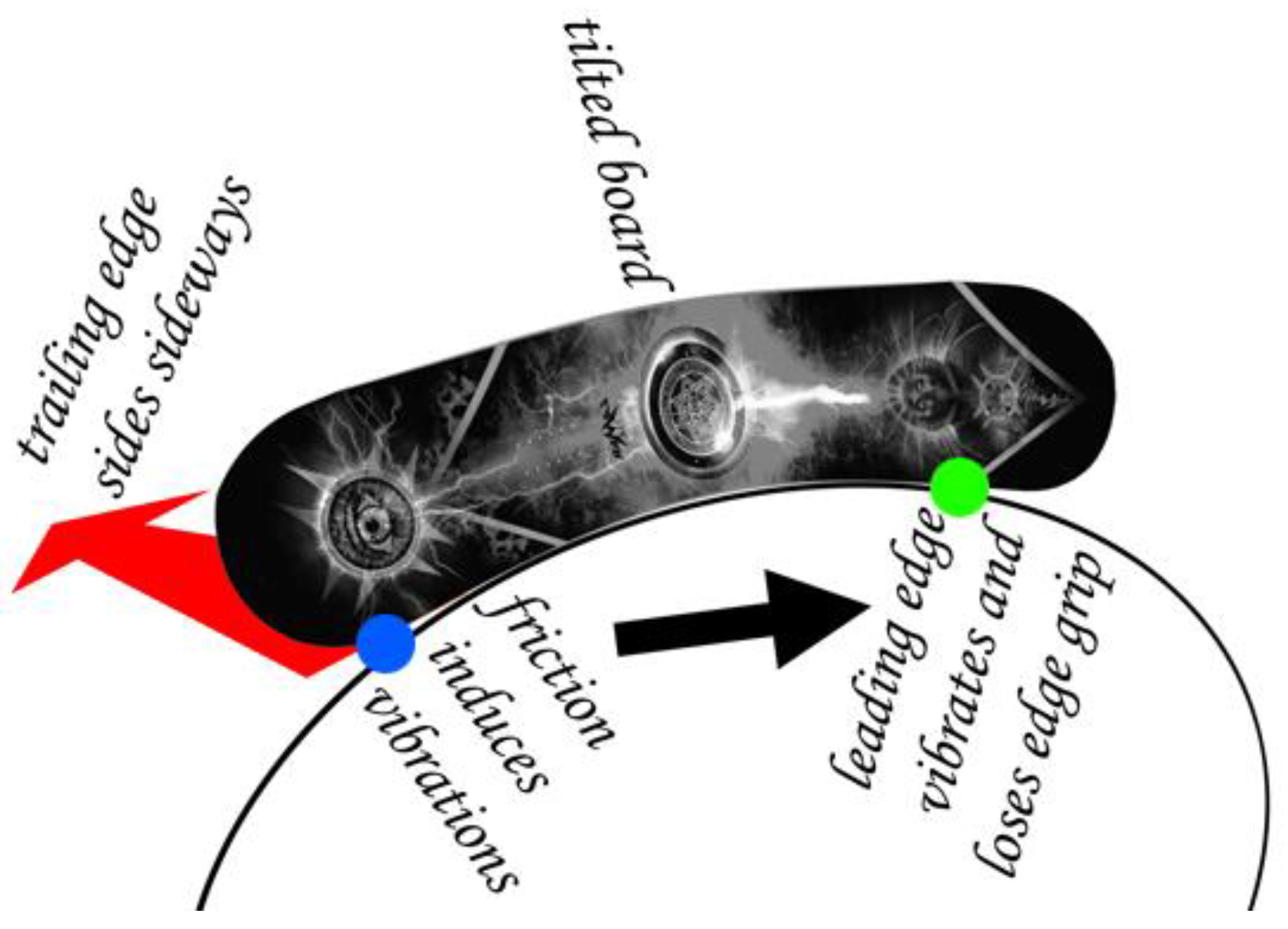
The explanation given in this paper hinges on the source of vibrations (
Figure 1). When carving, the board is tilted, loaded, and bent. While some minor vibrations can be induced during a perfect carving turn, the major source lies in imperfect carving turns, when the heel breaks out, slides sideways over the snow surface, and produces friction. Friction induces vibrations at the heel, which travel along the board, reach the shovel, and force the frontmost edge point, in contact with the snow, to oscillate sideways, thereby worsening the edge grip. In theory, the vibrations of the frontmost edge point can be due to bending modes of the board’s forebody and torsional modes of the shovel. The vibrations travelling along the board from rear to front may be dampened out with different damping ratios from mode to mode. According to Foss and Glenne [
2], the hardness of the snow affects the amplitude of the vibrations, but not the shape of the frequency response function (FRF). In skis, with the bindings placed in the centre, the resultant load deflects the ski fully when carving. Snowboards, however, are loaded by both legs simultaneously, and the bindings are located off-centre. Therefore, the centre section of the board is not fully deflected when carving, and consequently the centre edge is not entirely in contact with the snow surface. This principle can compromise the precision of the carving turn and causes the edge of the heel to slip sideways (
Figure 1).
In summary, the specific and relevant literature suggests that a highly active torsion mode is responsible for poor edge control, and that edge grip is related to the torsional stiffness of the board’s body. It is therefore paramount to find a method for assessing the edge grip of a snowboard by means of modal analysis.
The aim of this paper is to measure the oscillation amplitude of the foremost edge point at the shovel of two snowboards across the FRF in tilted, loaded, and bent boards, while inducing vibrations at the hindmost edge point of the heel. In addition to comparing two different boards, several tilt angles have to be tested to assess the displacement of the foremost edge point in relation to the tilt angle. In contrast to identifying the vibration modes from the mobility or accelerance spectrum, this study analyses the modes from the displacement spectrum, by means of a fast and reliable identification method. The novelty of this method is, compared to the existing literature, to investigate specifically the shovel of a tilted and loaded snowboard to identify the vibration modes that lead to edge grip failure, and to extract a single measure to quantify the strength of the edge grip.
2. Materials and Methods
To identify the bending and torsional modes, snowboards are usually analysed in free-free conditions [
4]. However, to simulate a carving turn, the snowboard has to be tilted and loaded by the resultant of gravitational and centrifugal forces, such that the board bends under this load (enabled by the sidecut radius) and generates the arc of the carving turn along its deflection.
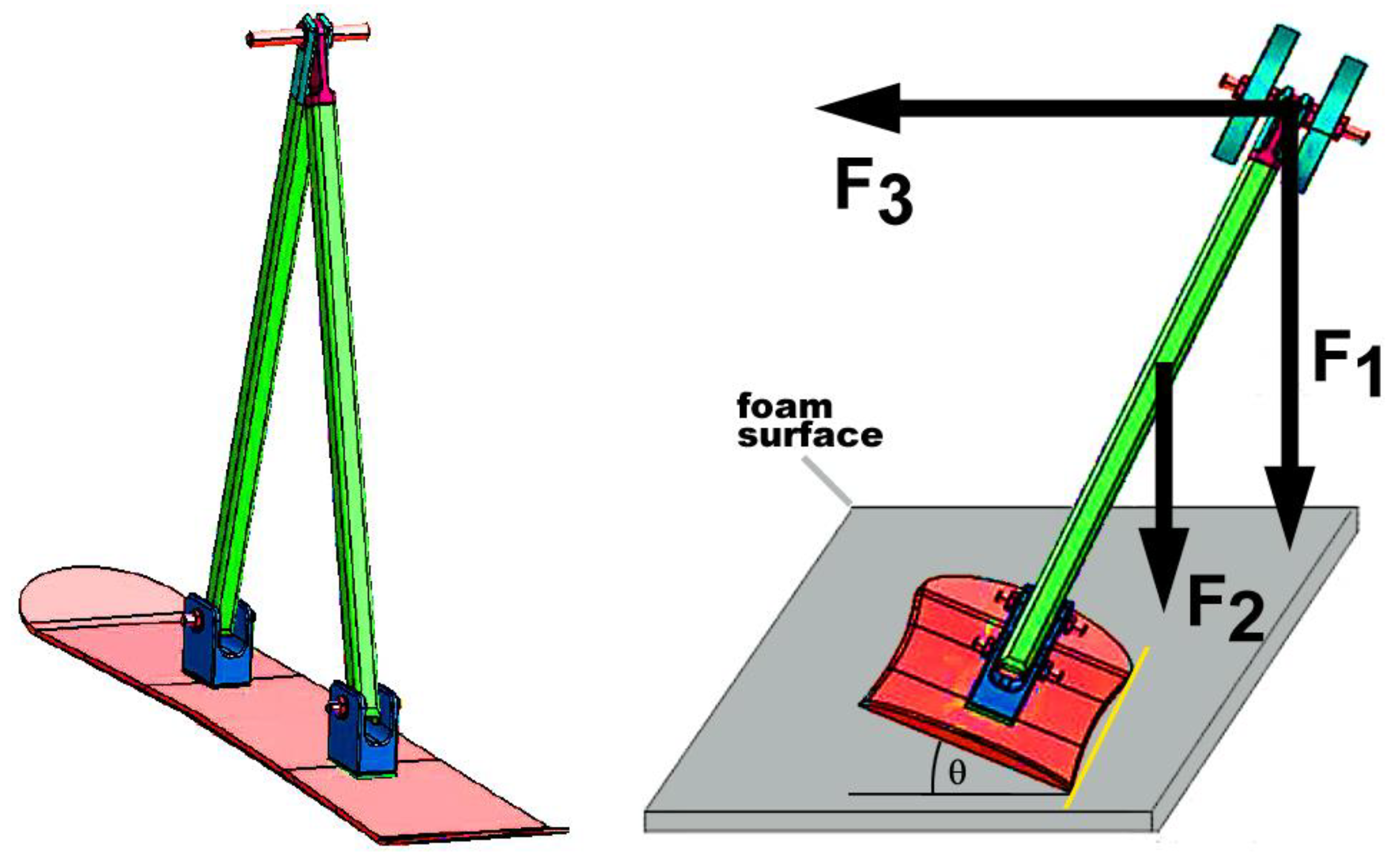
For this purpose, a triangular test rig (
Figure 2) was built, connected to the binding holes of the board. The two beams were joined by three revolute joints to the binding sites and to each other, thereby allowing movement when the board bends under an added load of 20 kg. The distance between the centre of the added mass and the board was 0.906 m. The mass of the test rig was 11 kg. The boards were tilted at four different angles, 35°, 42.5°, 50°, and 60°, measured with an inclinometer. The loading condition of the board depended on the situation when the edge grip deteriorated or was entirely lost (
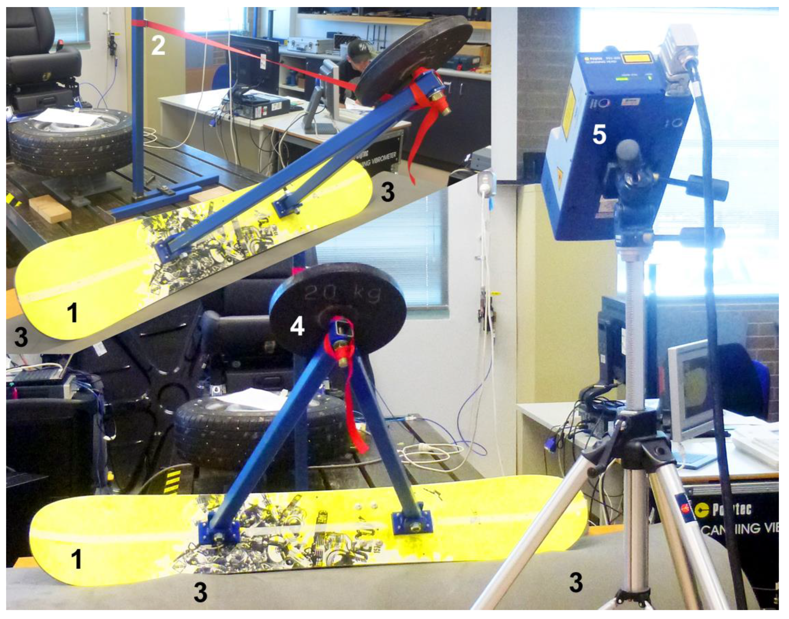
Figure 1). The free body diagram of a turning snowboarder involves the following forces: gravitational force (vertical), centrifugal force (horizontal), and the ground (or snow) reaction forces, which act perpendicularly (normal force) and tangentially (friction forces) to the board. The test rig was secured by an inelastic belt to a post (
Figure 3), which kept the board in a stable position. The belt force corresponded to the centrifugal force when performing a turn. The resultant load (
Figure 2) of gravitational and belt forces (in moment equilibrium about the edge), perpendicular to the board depended on the inclination angle and was approximately 106, 148, 199, and 286 N at tilt angles of 35°, 42.5°, 50°, and 60°, respectively.
Two snowboard decks, Salomon Prospect 160 (board A) and Rossignol Decoy 157 (board B), were tested five times at each inclination angle. The edge of the boards was placed on an elastic closed-cell polyurethane foam mat, characterized by the following parameters: density: 34 kg/m3; thickness: 20 mm; compressive stress: 240 kPa at 0.5 strain (ASTM D3574 C). The surface was smooth, formed by the tough outer skin of the foam. The surface was selected from the following criteria: the board’s edge had to indent the surface to be kept in place and simultaneously allow sufficient movement to be measured by the laser vibrometer.
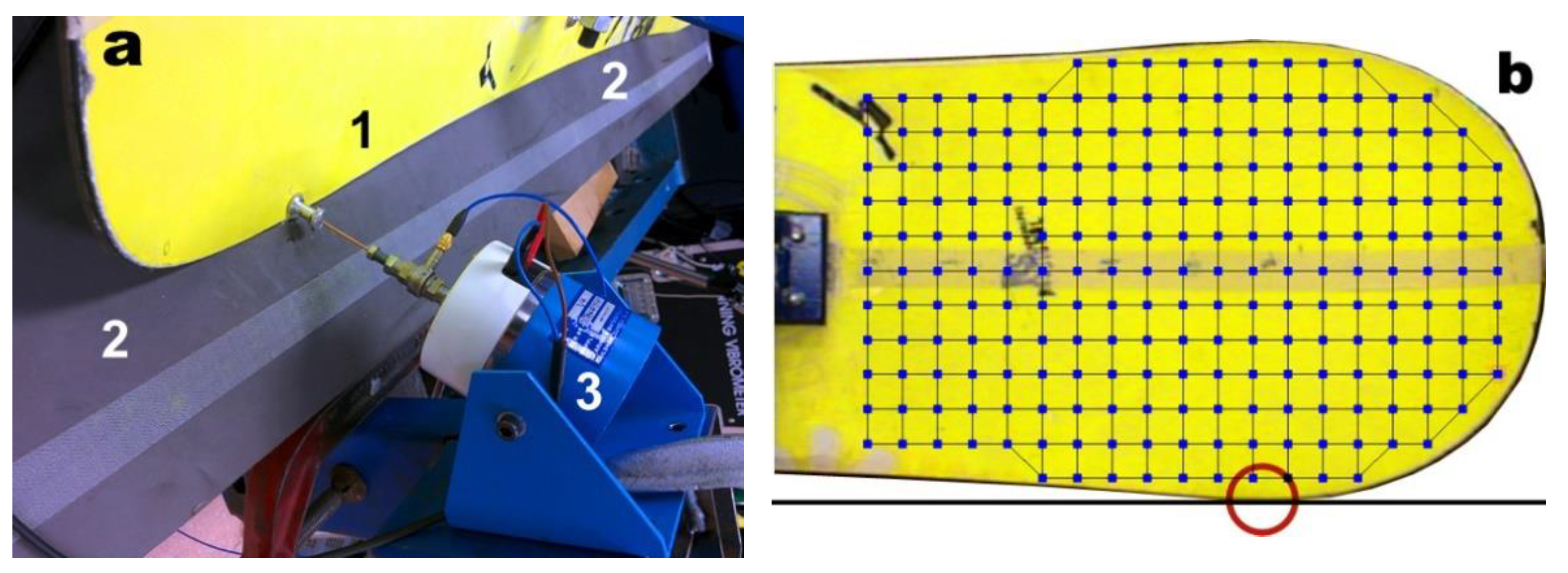
The shovel of the decks was scanned with a laser vibrometer (PSV 400-1D, Polytec, Waldbronn, Germany). The laser head was inclined at the same angle as the board, such that the laser beam was aligned perpendicularly to the board. The laser vibrometer determined the velocity and displacement with laser interferometry (Doppler effect). An electro-magnetic shaker (Gearing & Watson Electronics V4, Gearing & Watson Electronics Ltd., Hailsham, UK) exerted the input force perpendicularly to the board. A PCB Piezotronics 221B02 impedance head assessed the coherence of the input force and laser vibrometer data. The Polytec system controlled and drove the shaker and laser head while simultaneously processing measurements from the impedance head and the laser head. The shaker was connected to the hindmost edge point at the heel (
Figure 4a), whereas the laser measurements were carried out on the shovel. The boards were excited with a swept sine signal from 5–200 Hz. The laser head scanned 115–225 points consecutively on the shovel by means of a rectangular grid (
Figure 4b) projected on the shovel. The resulting frequency response function (FRF) consisted of 1561 data with a frequency band from 5 Hz to 200 Hz and a 125 mHz resolution.
The following data provided by the Polytec software (Polytec, Waldbronn, Germany) were processed:
- -
coherence against frequency;
- -
FRF of the average displacement (in dB); and
- -
FRF of the of the displacement (absolute magnitude) of a single scan point (foremost edge point in this case). The displacement data were smoothed with a 2nd-order Savitzky–Golay filter at a window width of 35 data.
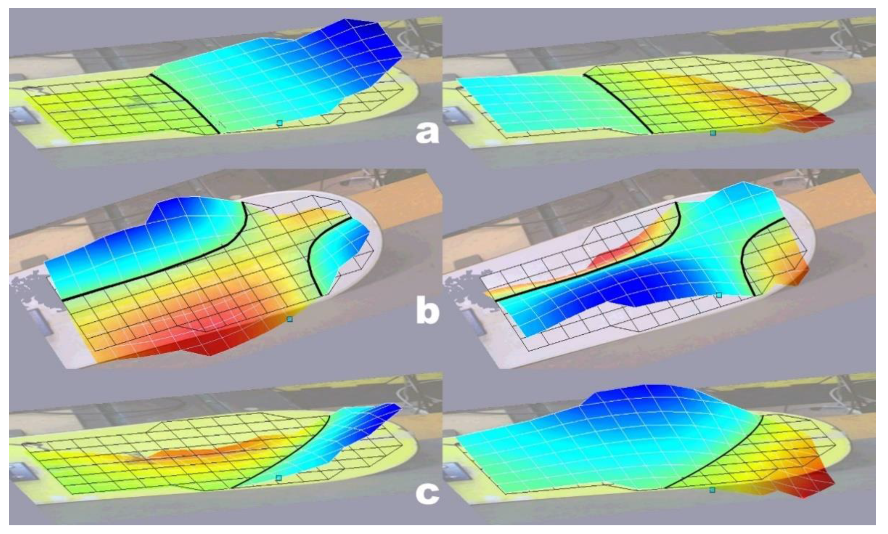
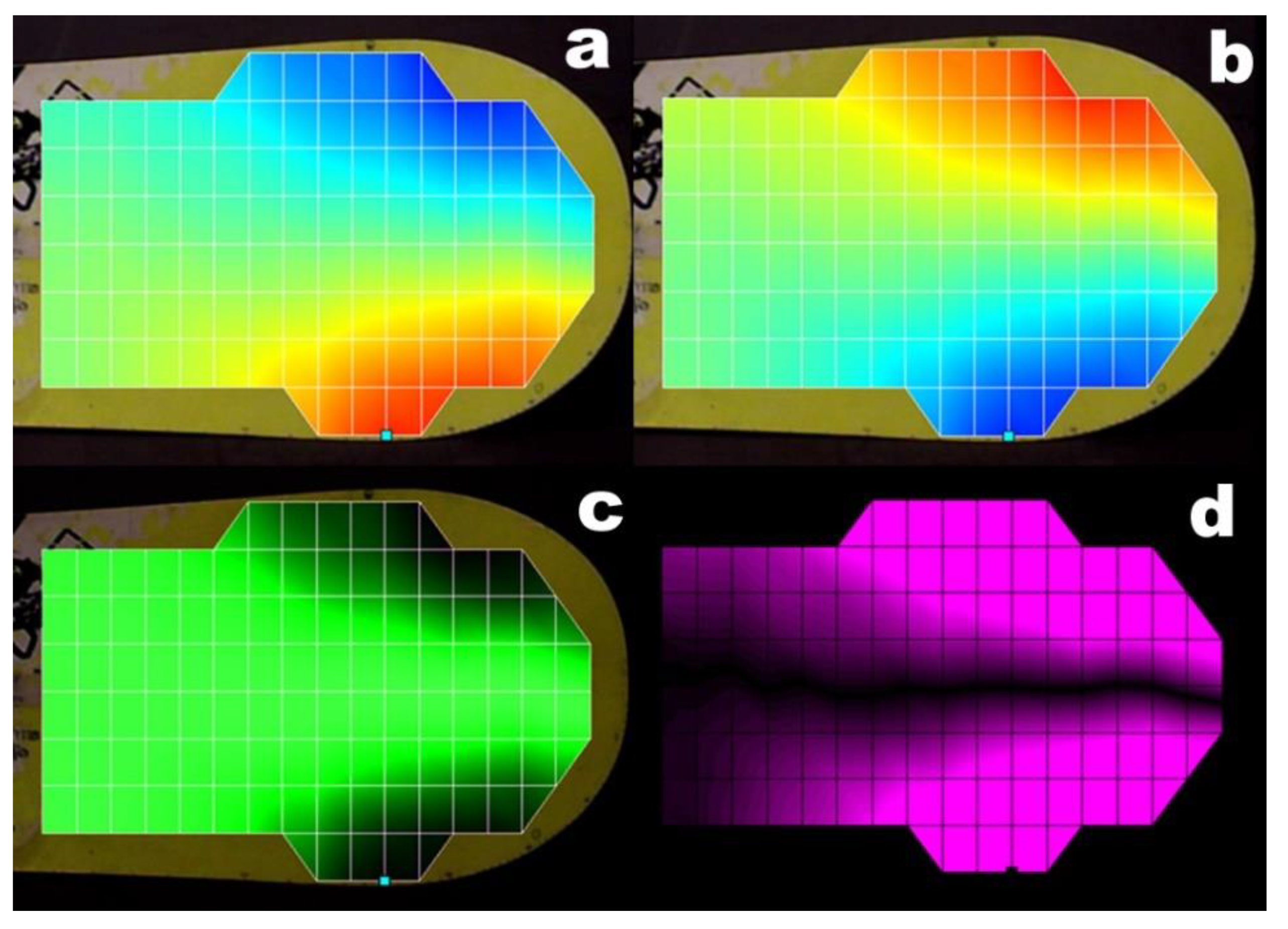
The bending and torsional modes including their node lines are usually determined from the colour-coded and animated displacement maps at a selected frequency (
Figure 5). In addition to the bending and torsional modes, the snowboard shovels exhibited combined modes, a combination of bending and torsional modes (
Figure 5c). The two displacement maps in top view and at the peak amplitude, separated by a phase angle of 180°, were copied and pasted into Adobe Photoshop on two different layers. The laser scan grids of the two layers were superimposed and the two layers were merged with the ‘difference’ blending mode. This procedure colours the highly mobile areas magenta and the immobile ones (node lines) black (
Figure 6). From the position and the shape of the node lines, the type of mode, that is, torsional, bending, or combined, was derived. Node lines which intersected the end of the shovel longitudinally (
Figure 5b), causing top and bottom edges of the tilted shovel to move in opposite directions, indicated the torsional modes (T). Node lines perpendicular to the cord of the board (
Figure 5a), causing top and bottom edges of the tilted shovel to move in the same direction, indicated the bending modes (B). Oblique node lines (
Figure 5c) indicated the combined torsional/bending modes (C), and therefore the transition from bending to torsion.
The integration of the displacement
x of the foremost edge point over a specified frequency range and dividing the result by this frequency range provided the average edge displacement or edge mobility measure (
EMM) for quantifying the edge stability.
where
f1 and
f2 are the frequencies across which
x continuously exceeded a magnitude of 0.2 mm throughout the active vibration mode. The magnitude of
x was integrated by using the trapezoidal rule for numerical integration.
The EMM should not be confused with the Mobility, i.e., the ratio of velocity to force, which measures how easily a structure vibrates. The ‘Mobility’ is of no use for edge control assessment, as only the actual displacement of the foremost edge point counts.
3. Results
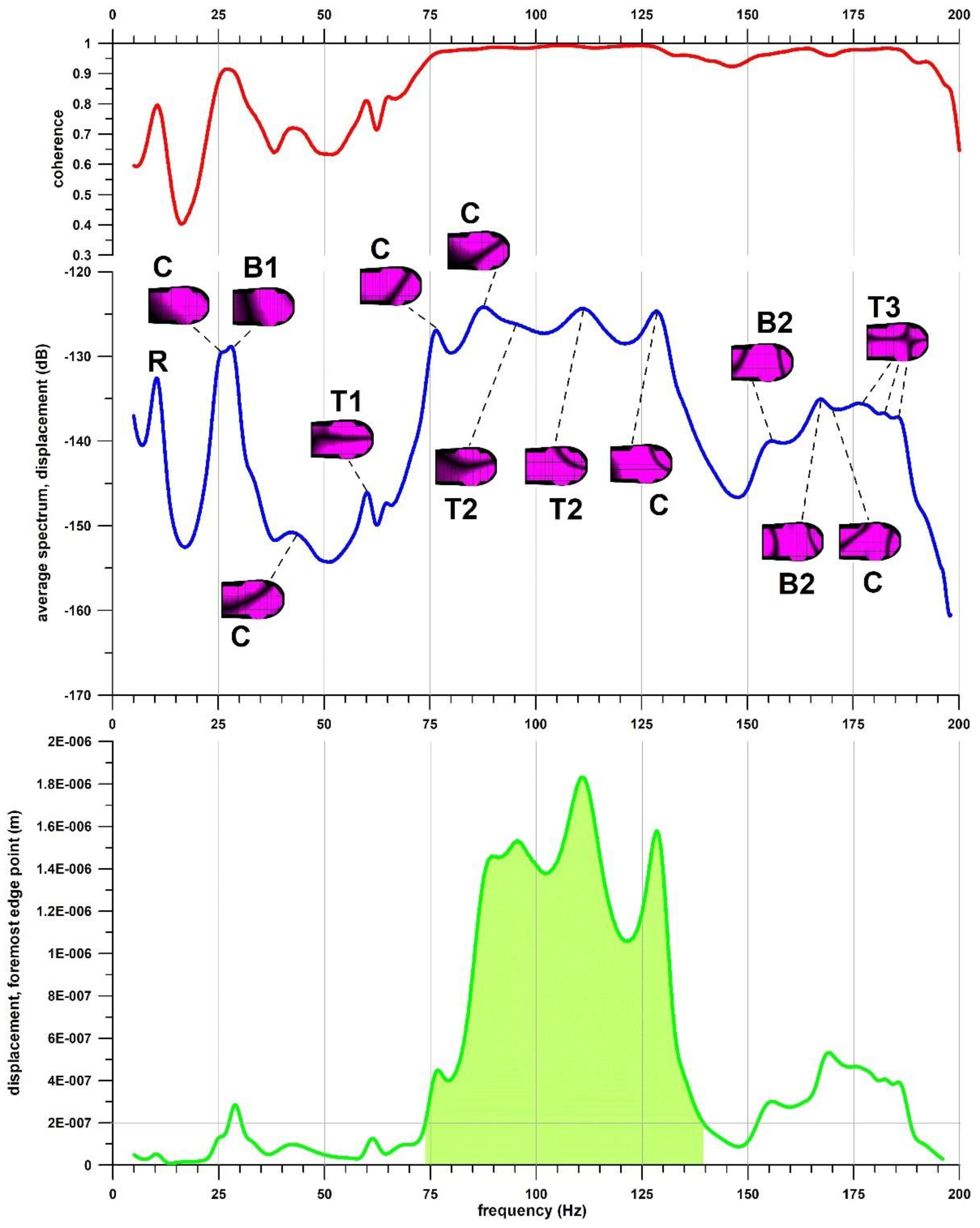
The shovel of a tilted and loaded snowboard vibrated with bending, torsional, and combined modes (
Figure 7 and
Figure 8). The coherence function, measuring the power of the output signal caused by the input, exhibited a high correlation between output and input in the resonance frequencies, resulting in clear mode shapes (
Figure 7 and
Figure 8). The first spike of the FRF at 10 Hz represented the rigid body motion (R) of the shovel, rotating about the edge contact line. Shovel A was torsionally stiffer (T1 and T3) than shovel B, except for the 2nd torsional mode (T2 adjacent combined modes;
Table 1). Shovel B was stiffer in bending modes (
Table 1).
The edge mobility measure (
EMM) of both boards increased as the tilt angle did. The
EMM of shovel A was less than the
EMM of shovel B (
Figure 9) at smaller tilt angles, and higher than the
EMM of board B at greater angles. This result indicates that board A performed better in terms of edge control in wider curves and board B in narrower curves. The average data per tilt angle are shown in
Figure 9. The mode responsible for edge control was the 2nd torsional mode (T2;
Table 1) and its adjacent combined modes, in which the frontmost edge point at the shovel exhibited its highest amplitude (
Figure 7 and
Figure 8).
4. Discussion
Being torsionally stiffer in free-free conditions (board A [
4]) or tilted and placed on the edge (
Table 1, T1 and T3) does not necessarily mean that the edge control is better. Moreover, the mode responsible for the edge control (T2) exhibited the same frequency range in both boards. The modes of an entire snowboard in free-free conditions cannot be compared to the modes of the shovel in loaded and tilted conditions. The statement by Foss and Glenne [
2] that a highly active torsional mode is responsible for less edge control was confirmed in this study.
In this present study, many combined (torsional and bending) modes (
Figure 5c) were found on the FRF (
Figure 7 and
Figure 8). These combined modes result from individual bending and torsional modes, coincidentally occurring at the same frequency range. They can be identified from a node line located between the standard bending and torsional node lines. Gosselin et al. [
5] also noticed ‘mixed’ bending–torsional modes in skis.
The fact that different literature sources (e.g., [
2,
4,
5,
6]) report smaller frequencies in bending and torsional modes compared to the present study is explained as follows. The literature has so far investigated the frequencies of snowboards and skis in free-free condition. The data of the present study refer to the frequencies of the shovel alone in the ‘semi’-clamped condition, where the term ‘semi’ indicates that joint between surface and board was not a rigid one, as it had to allow some movement. The difference between the entire board and the shovel alone lies in the density of the distributed measuring points. For example, the study by Fuss et al. [
4] used a coarse 15 × 5 grid, that is, 75 measuring points across the entire snowboard, including 20 points on each shovel; whereas in the present study, the shovel was covered with 115–225 measuring points. Twenty points on the shovel would not pick up the intrinsic vibrational modes with a substantially smaller displacement amplitude. The different support conditions (free-free, semi-clamped) add further differences to this issue, as does the different equipment (ski vs. snowboard).
The limitations of this study are related to the test setup. To create uniform test conditions, the boards’ edges were placed on soft elastic foam. The foam enabled the edge to move at the contact point or line. The test set-up was therefore entirely different from the plastically deforming snow. Simulating actual riding conditions on snow in a laboratory and keeping the snow properties uniform at each single test is difficult to achieve. Equally, sliding the heel of the board sideways over the snow surface for inducing vibrations in a laboratory is also too complicated and inconsistent when the same effect can be achieved by a shaker. The same issues apply to artificial snow surfaces [
7] such as the Snowflex (by Briton Engineering Developments LTD, Holmfirth, UK). The foam used as a support was very elastic with little damping. Snow, specifically softer snow, also dampens the vibrations of a snowboard. Vibration damping widens the mode spikes of the FRF, but otherwise does not change the displacement of the edge if the conditions are uniform. Damping is also expected to occur when the vibrations travel from heel to the shovel of the board. The magnitude of these displacements is certainly different from the ones when riding on snow, but there are also differences in magnitude between hard and soft snow [
2]. Furthermore, the displacement magnitude depends on the force exerted by the shaker.
There are three snowboard properties that should not be confused: (1) stiffness, (2) damping, and (3) edge movement. Increasing the stiffness (bending or torsional) shifts the mobility or accelerance spikes of the FRF to higher frequencies [
4,
5]. The effect of damping is measured from the damping ratio. The greater the damping ratio, the wider are the spikes of the FRF relative to their peak amplitude. The movement of any point on the board, and thus the edge movement corresponds to the peak amplitude of each spike on the FRF. This movement at the edge affects the maneuverability and the edge grip of the board and thus the edge control.
So far, the terms edge control and stability of a snowboard have never been defined properly other than the ‘
level of grip exhibited during turns’ [
1]. The current study introduces an explanation of the edge grip and control in
Figure 1 that is directly related to vibrations, their source, and their effect. The method used in this paper provides a reliable test for assessing the edge control and stability of a snowboard under standardized test conditions.
5. Conclusions
The principle of generating vibrations of a snowboard during a carving turn is that vibrations are induced at the heel when the heel slips sideways in an imperfect carving turn and travel through and along the board to the shovel, which vibrates and whose edge grip and control are affected.
For assessing the edge grip of a snowboard, this principle has to be mirrored in the methodological approach. Consequently, vibrations have to be induced at the heel, at the hindmost edge point, with a shaker for testing purposes. Furthermore, the board has to be tilted and loaded for replicating conditions of a carving turn and be placed on a soft surface for enabling vibrations at the frontmost edge point.
Comparing the shovels of the two boards, shovel A was torsionally stiffer in the 1st and in the 3rd mode, and shovel B was stiffer in the bending modes. The 2nd torsional mode proved responsible for large edge vibrations and displacements, and therefore for the edge control.
Although the trend of both boards was the same, namely less edge control at greater tilt angles, the variation of the edge control across the tilt angles ranged from minor (shovel B,
Figure 9) to major (shovel A,
Figure 9). Furthermore, when comparing the two boards, shovel A performed better at smaller tilt angles whereas shovel B performed better at greater angles (
Figure 9). These results lead to the conclusion that edge control in terms of the
EMM cannot be predicted and has to be tested for each single board.
Neither stiffness nor damping directly affects the edge grip. Although the shovels of both boards were equally stiff in the 2nd torsional mode, the shovels had different EMM, depending on the tilt angle. The effect of damping kicks in only after the completion of a carving turn, when the shovels are no longer tilted, so that the alignment of the shovels, horizontal and in full contact with the snow surface, provides probably more damping than the visco-elasticity of the board itself.


