Article

Effects of a Torsion Spring Used in a Flexible Delta Tricycle

1
Engineering and Technology Group, Department of Robotics, Automation and Mechatronics, KU Leuven Science, Gebroeders de Smetstraat 1, 9000 Gent, Belgium
2
Engineering and Technology Group, Department of Robotics, Automation and Mechatronics, KU Leuven Science, Andreas Vesaliusstraat 13, Bus 2600, 3000 Leuven, Belgium
3
Engineering and Technology Group, Department of Robotics, Automation and Mechatronics, KU Leuven Science, Wetenschapspark 27, Bus 15152, 3590 Diepenbeek, Belgium
*
Author to whom correspondence should be addressed.
Appl. Mech. 2022, 3(3), 1040-1051; https://doi.org/10.3390/applmech3030058
Submission received: 26 July 2022 / Accepted: 4 August 2022 / Published: 9 August 2022

Abstract

:
A new tilting delta tricycle is developed as a last-mile vehicle. This vehicle has a hinge between the front driver module and the rear cargo module to allow the driver to tilt while maneuvering. The driver module resembles a conventional bicycle without a rear wheel and the cargo module consists of a cargo area between two propelled rear wheels. The concept vehicle ensures proper handling qualities independent of the cargo. However, the driver module can still tip over when parked. Multiple solutions are being considered to improve the ergonomics of this vehicle. A metal-elastomer torsion spring with an integrated angle limit has the most advantages as this prevents the driver module from tipping over without requiring it to enable a mechanism while stepping off. Furthermore, the torsion system dampens vibrations while cycling and influences tilting while turning. These improvements are tested using the concept vehicle. The influence of this torsion system is calculated and validated with measurements. The influences of different torsion curves aimed to improve the low-speed stability are calculated.

1. Introduction

In the transition towards sustainability, there is a shift in last-mile delivery towards cargo bikes. Cargo bikes are cheaper, faster and more efficient for last-mile delivery in city centres compared to conventional vans [1]. This shift is visible with major courier companies such as DHL, UPS and FedEx testing cargo bikes in major cities including London, Berlin and Amsterdam with positive results [2,3,4]. However, current cargo bikes still have a limited cargo size and area which requires more trips [5]. Furthermore, cargo bikes are ideal for densely populated areas when logistic hubs are close to the city centre [6]. Improving the cargo area and using city containers can reduce and facilitate loading the cargo bike and eliminate the need for a transportation hub. Current cargo bikes are primarily developed for private use. Novel cargo bikes are developed for last-mile delivery and are able to transport city containers and a maximum payload of 250 kg. These cargo bikes are already replacing courier vans and have the potential to deliver 85% of all last-mile deliveries [7]. A cargo bike was developed to improve the cargo capacity and handling qualities [8]. This concluded in a tilting delta tricycle. The tricycle consists of a tilting driver module and a level cargo module. Tilting allows for a maneuverable vehicle. However, the driver module can tip over. Furthermore, the tilting design causes low speed instability just as on a conventional bicycle. Different methods are reviewed to prevent tipping over and improve the low-speed stability. A torsion system implements a counter-tourque that prevents tipping over and improves the low-speed stability. The influence while turning is reviewed and calculated for and an optimal counter-torque is considered.

2. Concept

Cargo bikes require high comfort standards. The courier has to drive the bike the whole day so proper stability and controllability are required. A heavy payload increases the need for a stable vehicle which prevents rolling over during manoeuvres and the desire for a low cargo hold. A wide wheelbase of multitrack vehicles provides extra stability. Furthermore, cycling multitrack vehicles on bad road conditions worsens the comfort due to lateral shocks caused by cycling through potholes with one side of the vehicle. Without back support as present in a car seat, the driver must be able to tilt during manoeuvres to have a comfortable driving feeling. A proper suspension can absorb the lateral accelerations due to bad road conditions but is a complex and expensive component of the vehicle.
Creating a hinge between the cargo module and the driver module allows the driver to lean in manoeuvres. This improves the driver’s comfort and allows the driver to lean while manoeuvring similar to a traditional bike. An extra advantage over long johns is the cargo load has a limited influence on the handling qualities of the vehicle.
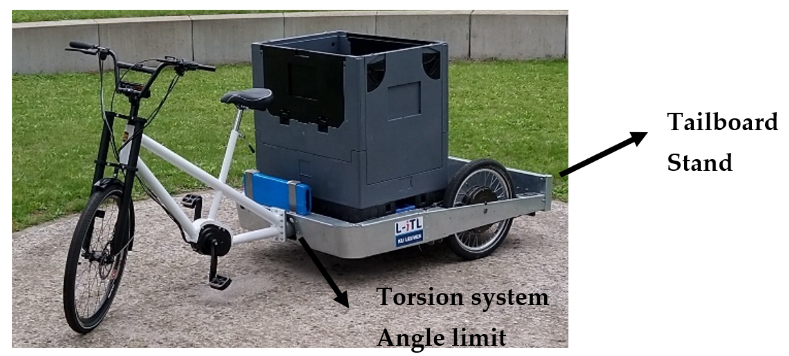
The requirements of the vehicle resulted in a flexible delta tricycle as seen in Figure 1 [8]. The concept vehicle consists of a cargo module and a driver module that are connected with a hinge allowing the driver module to tilt. The cargo module has two rear wheels each equipped with a hub motor for propulsion. The cargo area is placed between the wheels at a minimal ground clearance. The driver module is equipped with a pedal generator. The pedal generator works as a generator and has a virtual gearing with the hub motors. This design allows a wide and low cargo area with the ability to place a high city container without obstructing the driver’s view. The flexible frame allows the driver to lean during manoeuvres as with a traditional bicycle. The concept has proven to have proper handling qualities [9].
The extra degree of freedom allows the driver to shift the centre of gravity inwards. It allows the vehicle to perform stable manoeuvres at high speed without the risk of toppling over which is present with fixed frames tricycles [10].
The handling qualities of the concept vehicle were tested through an extensive set of manoeuvres and resulted in proper handling qualities [9]. The flexible frame makes the vehicle extra nimble. However, the manoeuvres used were tailored to multitrack vehicles without taking tilting vehicles into account. These tests excluded stability tests at low speed. Traditional multitrack vehicles are tri- or quad cycles with a fixed frame. Due to the wide wheelbase, these vehicles will remain upright while manoeuvring at low velocities and while stationary. A flexible delta tricycle has similar self-stabilizing properties as a traditional bicycle. These self-stabilizing properties only have a minimal effect at low speeds resulting in more effort for the driver to remain stable at low velocity [11].
When the driver module is placed upright it can remain vertically whilst stationary. However, this is at an unstable equilibrium. A small force can shift the centre of gravity of the driver module outside of the wheelbase and result in the driver module falling over. This is additionally caused by the rotation of the steer. Rotating the steer moves the wheelbase even further from the centre of gravity. Multiple methods to improve this concept in low-speed stability and stationary stability are examined and weighed against each other to obtain a solid result.

3. Tilting/Tipping Over

DIN 79,010 is currently the only cargo bike safety standard. This is however a German standard and is currently not mandatory. There is no European standard for cargo bikes, however, the future European standard will most likely be based on the DIN standard as this has happened before for a similar subject [12]. The standard described multiple aspects such as braking, dynamic stability and parking stability. The parking stability describes the testing procedure to evaluate the parking capability. The standard requires the vehicle to be able to be parked at inclinations of 8% (4.6°) sideways and longitudinally uphill and downhill of 10% (5.7°), as seen in Figure 2. This standard however does not state what is defined as fall/roll over for a flexible multitrack frame. The driver module could completely fall over while the cargo module remains upright. Furthermore, the driver module could tilt at a certain angle, but no restriction is stated on what is allowed.

3.1. Bicycle Stand

Similar to a traditional bike, the driver module can be equipped with a side stand that acts as extra support to prevent the module from tipping over at one side. This is used in the “Cube concept dynamic cargo”, calderas one from Sblocs, “electric Cargo Trike concept” from James Dyson Foundation and “butchers and bicycles”. This is an obvious solution and can be equipped using standard side stands used for bicycles. Other variants can be used to support the cargo area while handling cargo.
The traditional side stand is placed behind the pedals or at the rear wheel and when closed, it extends backwards. Mounting a traditional stand on the concept driver module would collide with the wide cargo module. Lengthening the wheelbase would create extra room but reduces the vehicle’s manoeuvrability. Furthermore, using the stand can cause difficulties. The side stand only prevents the vehicle from falling to one side. Just like with traditional bicycles, when placed on a hill or uneven terrain, the driver module could tip over. Moving or rotating the bicycle to park it stably is much easier with a bicycle than doing the same with the concept vehicle due to the extra weight and the bigger clearance circle.
This method only aids the stability of the bicycle while stationary. The low-speed handling qualities are not affected by a bicycle stand. Due to the reorganization of the city centre, cargo bikes can cycle through busy shopping/walking streets and occasionally have to cycle slowly. Improving the low-speed stability would be beneficial. Furthermore, a stand requires opening and closing manually every time the driver steps off, which is a substantial amount if the vehicle is used for last-mile delivery.

3.2. Locking Mechanism

To keep the driver module upright, the vehicle can be equipped with a locking mechanism. A locking mechanism can lock the tilting mechanism preventing the vehicle to tilt. This is commonly used in flexible tadpole tricycles like “Butchers and bikes”, “pro cargo CT1”, Chike, and “HNF-Nicolai CD1”. Tadpole tricycles do not have a separate driver and cargo module. The cargo area tilts with the cyclist just like a single-track vehicle. Poorly distributed loads would cause unwanted tilting or falling off the vehicle. The locking mechanism prevents this. Locking the tilting system offers the advantages of a fixed frame multitrack vehicle. The wide fixed wheelbase ensures a stable vehicle at low velocity and when stationary. This also allows the vehicle to remain upright when unmanned and eases mounting and dismounting. The driver still has to manually lock and unlock the tilting mechanism. Furthermore, the vehicle is less nimble when the tilting mechanism is locked. Cycling with or without the locking mechanism engaged is like cycling two different vehicles. A locked tilting vehicle has the same handling qualities as a fixed frame tricycle. The cyclist can forget if the locking mechanism is engaged. This could cause the cyclist to take a corner too quickly and end up in the vehicle tipping over.
An electronic locking mechanism can provide automatic locking. This engages the mechanism automatically depending on the velocity. This way the vehicle will always drive optimally. At low velocity and whilst stationary the vehicle is locked. This ensures a stable slow drive and keeps the vehicle upright when stopping and stepping off. At higher velocity, the vehicle can tilt ensuring proper manoeuvring capabilities.
To the author’s knowledge, this locking mechanism has not been implemented yet in delta tricycles. This is likely due to the lack of suspension in the cargo module of the vehicle. While the fixed frame improves the stability at low speed, the vehicle experiences uncomfortable lateral shocks when driving on bad road conditions or over speed bumps due to the limited suspension similar to fixed frame delta tricycles.

3.3. Angle Stop

The use of a stop limiting the tilting angle is a way to prevent the driver module from completely tipping over. This is automatically incorporated in the majority of the tilting tricycles but varies in the angle limit. The angle limit requires a high enough range, since limiting the tilting angle reduces the manoeuvrability of the vehicle. This was tested by changing the tilting angle of the concept vehicle. For example, changing the maximum tilting angle from 30° to 25° reduces the maximum possible speed when driving a circle of a radius of 4 m from 17 km/h to 14 km/h. During evasion manoeuvres, the test subject was not able to perform an evasive manoeuvre with the reduced angle limit at the maximum velocity which was possible with an angle limit of 30°. The test subject also stated the angle limit gives a sudden shock when reaching the angle limit at 25°. This did not occur during the test using the 30° angle limit. The shock of the angle limit can be reduced by adding a damper.
The results were unexpected since the majority of delta tricycles have a tilting limit of 18–20° [13]. The tests concluded a 30° angle limit is required. This is however an extreme position to pull/push the driver module upright before getting on the vehicle. Tilting this far would also cause the steer to extend 40 cm outside the width of the vehicle. This can cause the steer to fall onto a nearby vehicle.

3.4. Torsion System

A different solution is equipping the hinge with a torsion system. This torsion system creates a torque resistance depending on the tilting angle. The resistance will push the vehicle upright. The vehicle is still able to tilt and aids in the stability of the vehicle at low velocity. This system is present in tadpole tricycles as “the cargo e-bike concept” of Volkswagen [14].
The torsion system in the concept vehicle is made up of a hollow square tube with a smaller square tube placed inside and rotated 45°. The outer tube is fixed with the cargo module while the inner tube rotates together with the driver module. The free space is filled up with an elastomer as can be seen in Figure 3. This system is similar to a torsion axle used in trailers.
A torsion system is beneficial for multiple reasons. The torque ensures that the driver module remains upright and prevents it from tipping over. This eliminates the need for a parking stand and eases mounting and demounting while delivering parcels. The torsion system also acts as a soft angle limit as the torsion increases according to the tilting. This will also improve the stability of the vehicle at a lower velocity. The counter torque present during tilting will push the driver module to the centre. This counter-torque will be limited so it will not prevent the driver from falling over but will facilitate for the driver to remain stable. The torsion system has an additional advantage. The hysteresis present in this system acts as a damper reducing possible vibrations that can occur while driving. The counter torque requires a certain torque/tilt curve to provide proper aid in the handling qualities of the vehicle. If the counter-torque is too low, the vehicle will simply fall over when not supported and driving slowly requires just as much concentration as without the torsion system. When the counter-torque is too high, the driver is only able to tilt too little during manoeuvres. This causes the driver to endure extra lateral acceleration similar to a fixed frame. The torque/torsion curve can vary depending on the properties and size of the elastomers.
The concept vehicle performed the manoeuvres equipped with the previously mentioned torsion system. The torsion spring does not influence the comfort of the driver during high-speed manoeuvres [9].
Testing the handling qualities shows that manoeuvres such as a double lane change can be performed at maximum velocity. During this manoeuvre, the cyclist only experiences a lateral acceleration of 2 m/s2. This is a comfortable lateral acceleration in a cycling seat position [15].

4. Used System

The vehicle concept incorporates multiple of the previously mentioned systems as seen in Figure 4. The concept vehicle incorporates a stand, torsion system and angle limit in the design.
The concept vehicle has a tailboard on the back of the cargo module. The tailboard can rotate downwards and support the cargo module. This prevents the vehicle from tipping and raising the front wheel when loading and unloading a container. The incorporation of a torque system and angle limit in the hinge ensures a simple implementation in the concept vehicle. This system is chosen because it will prevent the driver module from falling over without the need to enable a locking mechanism. Furthermore, the torsion system can also aid in low-speed stability whilst having little to no influence on the manoeuvrability of the vehicle.

Effects of Torsion System on Stationary Stability

The concept vehicle is equipped with a torsion system that creates counter-torque when tilting. This provides an incorporated soft angle stop which limits the tilting and in extreme cases, an angle limit of 30° is used. A flexible torsion system was implemented in the concept vehicle as high-speed manoeuvrability has priority over low-speed stability. To acquire its torque/angle curve a torque is applied in an upward and downward motion and the angular deflection is measured. The graph, as seen in Figure 5, is obtained. A third-degree polynomic trendline is fitted on the upper side for further calculations.
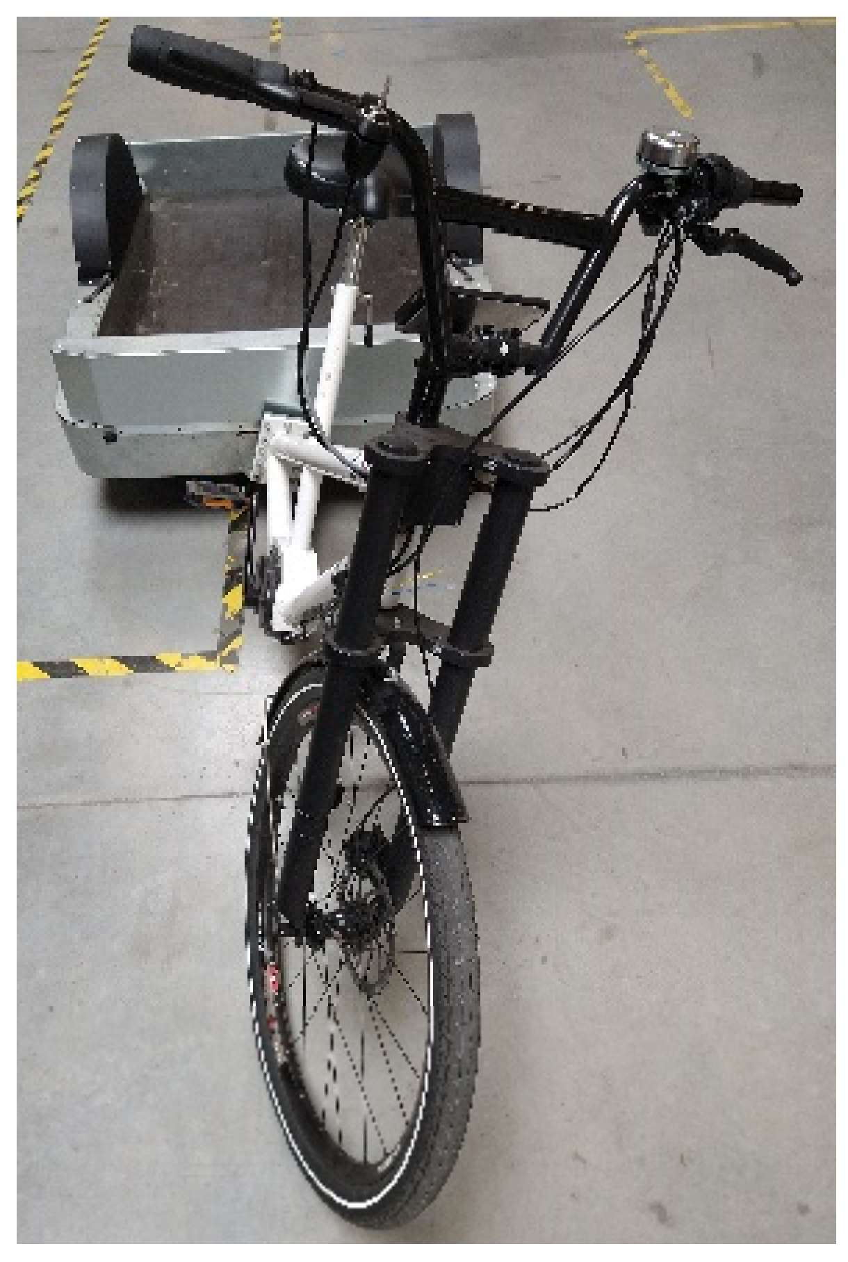
The elastomer torsion system has a typical hysteresis which provides a dampening effect. This reduces vibrations while cycling. The currently equipped torsion system has a zone between −5° and +5° where the torsion system creates almost no counter-torque. This small counter-torque is still enough to keep the driver module upright without a driver. However, when disturbed or while handling cargo, the driver module tilts between 14° and 17°.
This is measured after creating disturbances by loading and unloading the cargo hold. When the driver module is pushed to the angle limit, the driver module tilts back to a maximum of 22° as shown in Figure 6. Tilting 22° accounts to the steer extending about 30 cm outside the width of the vehicle.
The torque the driver module applies on the hinge is calculated using Equation (1).
T d m = M d g sin a c o g
With:
T d m = t o r q u e   o f   d r i v e r   m o d u l e   N m
M d = d r i v e r   m o d u l e   m a s s   k g
g = g r a v i t y   9.81   m / s 2
c o g = c e n t r e   o f   g r a v i t y   d i s t a n c e   m
a = t i l t i n g   a n g l e   °
The centre of gravity distance is measured perpendicular to the hinge’s axis. While parked, the driver module is unmanned and has a mass of 15 kg and a centre of gravity distance of 0.3 m perpendicular to the hinge’s axis. While cycling the driver module is manned and has a mass of 90 kg and as centre of gravity distance of 0.8 m.
Equation (1) is however a simplification since there are multiple unknown variables. The steer can rotate which moves the point of support and creates an asymmetry in the centre of gravity. This has a bigger effect when the driver module is upright. When the driver module is tilted, the change is not that great. The steer is even pushed straight thanks to the geometry of the vehicle. Due to the uncertainty of the steer rotation and the small effect it has, this is neglected.
Furthermore, the weight distribution of the cargo module can create an additional force on the driver module. When the centre of gravity of the cargo module is inclining forward, the front wheel receives additional weight. This can create an additional torque in the hinge. In this concept, this has a limited effect due to the axis of the hinge intersecting with the contact point of the front wheel when positioned upwards.
The calculated moment created by tilting on a level surface intersects with the counter-torque at 13.25° as shown in Figure 7. When the vehicle is at a diagonal inclination of 8%, the driver module hinges between 18.5° and 22. 5°, resulting in a vertical inclination of 23.1° and 27.1°.
These calculations correspond to the measured values. Although the driver module stops tilting before the angle limit is reached, the driver module still tilts a decent amount which creates a tedious action when getting on the bike. Furthermore, the steer can extend 30 cm outside the vehicle’s width and fall onto close by vehicles. Increasing the counter-torque in the hinge will reduce this.
The torsion system has an influence while cycling. During manoeuvres, the driver tilts while cornering. Cornering causes the driver to lean inwards to compensate for the centripetal force. Cornering the vehicle at a certain radius at a certain velocity causes a centrifugal force as calculated in Equation (2).
F c = M d d V 2 r
With:
F c = C e n t r i p e t a l   f o r c e   N
M d d = d r i v e r   m o d u l e   a n d   d r i v e r   m a s s   k g
V = m e a n   v e l o c i t y   w h i l e   t u r n i n g   m / s
r = t u r n i n g   r a d i u s   o f   t h e   v e h i c l e   m
This centripetal force acts on the driver module and the driver pushes it outwards of the turn. Tilting inwards counteracts this thanks to gravity as seen in Equation (1). This creates a total torque in the hinge stated in Equation (3).
T h = F c cos a c o g     M d d g sin a c o g
With:
T h = T o r q u e   o n   h i n g e   N m
C o g = c e n t e r   o f   g r a v i t y   m
T h = T o r q u e   o n   h i n g e   N m
Without a torsion system T h is 0 Nm. When calculating it with the torsion system, T h is substituted by the torque/angle curve. This results in a decrease in tilting due to the counter torque. Equation (3) is compared with measurements performed on the concept vehicle. Using measurements of different manoeuvres corresponding tilting angles are gathered according to the turning radius and the velocity. Multiple manoeuvres are performed with the vehicle and turns are sorted according to turning radius and velocity. Figure 8 shows the measured tilting angle according to the turning radius. The colour is plotted according to velocity.
The measured and calculated tilting angles have a mean difference of 2°. Those differences can be explained due to simplifications in the equation. The driver who accounts for the majority of the driver module’s mass is considered rigid while this is not the case. During manoeuvres, the driver can rotate its torso, changing the centre of gravity. Taking a turn is never performed at a constant turning radius and velocity. Selected measurements are steady turns with a limited variation. The mean values during the turn are used for the calculations. The calculations are a simplification where the movement of the wheelbase due to steering and tilting is not taken into account as well as a slightly smaller turning radius of the driver module compared with the cargo module which is used to calculate the turning radius. The measurements are generated from manoeuvring tests which are conducted on pavement. However, the pavement is not completely flat, causing the cargo module to be slightly unlevel at times and influencing the measurement. The hysteresis present is also not taken into account.
Thanks to ability to tilt, the driver only experiences a fraction of the lateral acceleration compared to a fixed frame vehicle. While testing the maximum possible velocity driving a circle with a radius of 4 m the driver only experienced a lateral acceleration of 0.89 m/s2 while a fixed vehicle experienced 4.5 m/s2 [9]. The driver experiences less lateral acceleration with the concept vehicle. A comfortable lateral acceleration is stated to be below 0.9 m/s2 [15].
Due to the low torque the torsion system has at near-vertical positions, the improvement in low-speed stability is minimal. Just like with a conventional bicycle, extra concentration is required to cycle at low velocity compared to high velocity. The cyclist experiences a minimal difference with or without the torsion system at low velocity. Cycling above 10 km/h, the vehicle has self-stable properties and does not require the aid of a torsion system to remain upright. Increasing the torque stiffness can improve the low-speed stability and limit the parking tilting, but can limit the ability to tilt while turning. On a traditional bicycle, while cycling a straight line at 9 km/h, the roll angle remains between −1.5° and 1.5° [16]. To remain stable, the cyclist has to balance by tilting his torso or steering. To aid in the low -speed stability, the torsion system counter-torque should be equal or higher than the to compensate for the imbalance.
The torque created by the imbalance is calculated using Equation (1). Centripetal force is neglected as the stability in a straight line is considered. A rigid cyclist body is considered, meaning the cyclist does not lean in the opposite direction to aid in the balance. At a tilt angle of 1.5°, the driver module with the cyclist generates a torque of 24.39 Nm.
When the torsion system is 10 times stiffer, the counter-torque is higher as can be seen in Figure 9 and should improve the low-speed stability. This cannot be tested with the current prototype due to the difficulty of changing the torsion system. This stiffer torsion system reduces the tilting when parked but also reduces the ability to tilt while cornering. These changes can be calculated as before.
The changes while tilting due to the stiffer torsion system are calculated using Equation (3). These changes can be seen in Figure 10.
The stiffer torsion decreases the tilting according to the velocity. The influence is not shown over the complete turning radius as the vehicle’s velocity increases the minimum possible turning radius. During a big turning radius, the stiffer torsion spring causes little tilting reduction. This is a minor change and has a limited influence on the manoeuvrability. However, the influence of the torsion spring increases when the velocity is increased or at a smaller turning radius. In extreme cases, for example when cycling at 25 km/h through a 10 m turning radius, this can reduce the tilting angle by 8°. This results in an increased lateral acceleration of 1.5 m/s2 which is still considered as a normal driving acceleration [15]. While cycling normally, the stiffer torsion spring would only account to a tilting reduction of 2°.

5. Discussion

The torsion system with an integrated angle limit is an optimal choice. The torsion system meets the requirements. It prevents the driver module from tipping over. The system can easily and cheaply be integrated into a hinge and does not require any control/adjustment when starting/stopping unlike a locking mechanism or a side stand. Furthermore, the torsion system improves the handling qualities. The damping properties of the system reduce vibrations in the vehicle. Unfortunately, the driver module can still tilt 22° while parked causing the steer to extend 30 cm outside the vehicle’s width. The cyclist has to straighten the driver module every time he gets on the vehicle. Furthermore, the low torsion of the current torsion system does not aid in the low-speed stability. An increase in the stiffness of the torsion system results in a tilting angle reduction. The titling reduction during normal driving conditions is only 2 degrees.
This indicates the stiffer torsion system will improve the vehicle’s ergonomics further, but practical tests are required to find an optimal balance between low-speed stability and high-velocity manoeuvring.

6. Conclusions

A torsion system is implemented in the concept vehicle. The system meets all the requirements. It prevents the driver module from tipping over when parked. The driver module can still tilt 17° but will not fall over. The torsion system has a small effect while cornering. The vehicle can still tilt while driving. It does not interfere with the handling qualities of the vehicle The system even provides damping reducing vibrations while cycling. Although the torsion system provides enough counter-torque the module doe no’t fall over, an angle limit is still incorporated to ensure a maximum tilting angle in extreme cases. A stand is added to the cargo module to aid while loading and unloading.

Author Contributions

Conceptualization, J.D., P.S., E.D. and M.J.; methodology, J.D., P.S., E.D. and M.J.; validation, J.D., P.S., E.D. and M.J.; formal analysis, J.D., P.S., E.D. and M.J.; investigation, J.D., P.S., E.D. and M.J.; resources, P.S., E.D. and M.J.; data curation, J.D., P.S., E.D. and M.J.; writing—original draft preparation, J.D., P.S., E.D. and M.J.; writing—review and editing, J.D., P.S., E.D. and M.J.; visualization, J.D., P.S., E.D. and M.J.; supervision, P.S., E.D. and M.J.; project administration, P.S., E.D. and M.J.; funding acquisition, P.S., E.D. and M.J. All authors have read and agreed to the published version of the manuscript.

Funding

This research received no external funding.

Informed Consent Statement

Informed consent was obtained from all subjects involved in the study.

Conflicts of Interest

The authors declare no conflict of interest.

References

  1. Verlinghieri, E.; Itova, I.; Collignon, N.; Aldred, R. The Promise of Low-Carbon Freight; Possible: London, UK, 2021. [Google Scholar]
  2. Van Amstel, D.P. DHL Netherlands Presents Their new Cargo Bike: The Chariot; City Logistics: Durban, South Africa, 2021. [Google Scholar]
  3. FedEx. FedEx Express Continues Journey Towards Zero Emissions Delivery, as Edinburgh, Glasgow and Cambridge Become the Next UK Cities to Welcome E-cargo Bikes; FedEx: Memphis, TN, USA, 2021. [Google Scholar]
  4. UPS. Lessons from Our e-Bike Journey. United Parcel Service of America, Inc. Available online: https://about.ups.com/be/en/our-stories/innovation-driven/lessons-from-the-e-bike-journey-of-ups.html (accessed on 26 April 2022).
  5. Blazejewski, L.; Sherriff, G.; Davies, N. Delivering the Last Mile Scoping the Potential for E-Cargo Bikes Healthy Active Cities; Univeristy of Salford: Salford, UK, 2020. [Google Scholar]
  6. Naumov, V. Substantiation of Loading Hub Location for Electric Cargo Bikes Servicing City Areas with Restricted Traffic. Energies 2021, 14, 839. [Google Scholar] [CrossRef]
  7. Ferguson, J. Cargo Bike Crazy: The Potential of Delivering Goods by Bike. Available online: https://ecf.com/news-and-events/news/cargo-bike-crazy-potential-delivering-goods-bike-0 (accessed on 24 March 2022).
  8. D’hondt, J.; Juwet, M.; Demeester, E.; Slaets, P. Development of an electric tricycle for service companies and last-mile parcel delivery. Transp. Probl. 2022, 17, 2. [Google Scholar] [CrossRef]
  9. D’hondt, J.; Degryse, D.; Slaets, P.; Demeester, E.; Juwet, M. Handling Qualities of a New Last-Mile Vehicle. J. Transp. Technol. 2022, 12, 137–158. [Google Scholar] [CrossRef]
  10. Rodríguez Licea, M.A.; Vazquez Rodríguez, E.A.; Perez Pinal, F.Z.; Prado Olivares, J. The Rollover Risk in Delta Tricycles: A New Rollover Index and Its Robust Mitigation by Rear Differential Braking. Math. Probl. Eng. 2018, 2018, 4972419. [Google Scholar] [CrossRef] [Green Version]
  11. Meijaard, J.P.; Papadopoulos, J.M.; Ruina, A.; Schwab, A.L. Linearized dynamics equations for the balance and steer of a bicycle: A benchmark and review. Nelineinaya Din. 2013, 9, 343–376. [Google Scholar] [CrossRef] [Green Version]
  12. Oortwijn, J. Development Starts for Cargo Bikes’ Safety Standard. In Bike-EU; Bike Europe: Delft, The Netherlands, 2017. [Google Scholar]
  13. Sevic Emobility 2017 Catalogue; Sevic Systems SE; Bochum, Germany. 2017. Available online: https://sevic.com/en (accessed on 3 August 2022).
  14. Volkswagen. Local logistics Made Easy: The Volkswagen Cargo e-Bike. Available online: https://www.volkswagenag.com/en/news/stories/2019/07/urban-innovative-sustainable.html# (accessed on 25 May 2022).
  15. Bae, I.; Moon, J.; Seo, J. Toward a Comfortable Driving Experience for a Self-Driving Shuttle Bus. Electronics 2019, 8, 943. [Google Scholar] [CrossRef] [Green Version]
  16. Cain, S.M.; Ashton-Miller, J.A.; Perkins, N.C. On the skill of balancing while riding a bicycle. PLoS ONE 2016, 11, e0149340. [Google Scholar] [CrossRef] [PubMed]
Figure 1. Last-mile vehicle concept [8].
Applmech 03 00058 g001
Figure 2. Lateral inclination, downhill inclination and uphill inclination.
Applmech 03 00058 g002
Figure 3. Torsion axle and corresponding spring characteristic.
Applmech 03 00058 g003
Figure 4. Tilting concept vehicle.
Applmech 03 00058 g004
Figure 5. Measured torque/angle curve with corresponding upper trendline x = 0.0013 × a³ + 0.016 × a² + 0.0851 × a + 2.3532.
Applmech 03 00058 g005
Figure 6. Tilting driver vehicle while parked.
Applmech 03 00058 g006
Figure 7. Stationary tilting curve on a level and inclined surface.
Applmech 03 00058 g007
Figure 8. Tilting angle according to turning radius and velocity. Calculations are performed at 5, 10, 15, 20, and 25 km/h.
Applmech 03 00058 g008
Figure 9. Graph of the current and 10 times stiffer torsion system. These are compared with the torsion the driver module with and without cyclist creates on level surface and inclined (8%).
Applmech 03 00058 g009
Figure 10. Tilting calculation of torsion system and 10× stiffer torsion system and difference due to torsion system.
Applmech 03 00058 g010
Publisher’s Note: MDPI stays neutral with regard to jurisdictional claims in published maps and institutional affiliations.