1. Introduction
Sensory data acquisition in mechatronic systems is an essential step towards the digitalization of industrial processes and technical systems [
1]. These data can be used, for example, in digital twins to provide information on the current state of the system [
2,
3,
4]. The quality of the measured data can be increased with the increasing proximity between the measurement location and relevant process [
5]. Unfortunately, it is not always possible to locate sensors in situ or in close proximity to the relevant process, especially not in retrofit applications. One approach to solve this problem, besides the integration of low-cost sensor modules into existing machine elements, is the sensory utilization of standardized machine elements themselves, such as rolling bearings or couplings. This counters the challenge presented by the fact that the integration of sensor modules in machine elements often involves changes to the interfaces or the required installation space, or leads to a mechanical weakening of the machine element. Sensory utilizable machine elements bypass these difficulties as the electrical properties of the machine elements are used directly in a sensory way [
6]. However, machines cannot be realized only by combining standardized off-the-shelf components. Further components are required, which must be developed specifically for the respective application. For these components, which are called design elements in this paper, there are design principles and established concepts especially in the mechanical domain [
7]. It therefore appears reasonable to use these design elements in a sensory manner as well. For this purpose, the classification of sensing machine elements will be transferred to design elements in this paper. Subsequently, in the context of a scoping review, exemplary concepts of sensory utilizable design elements will be presented. Therefore, the aim of this scoping review is to give an overview of exemplary application concepts, highlight potentials arising from the use of sensory utilizable design elements, and point out technical and methodical challenges, which have to be addressed in future research.
1.1. Classification of Design Elements
Vorwerk-Handing et al. [
6] published a classification of different types of machine elements, based on the work of Stücheli and Meboldt [
8]. They assume machine elements to have standardized mechanical interfaces and to allow a dimensioning and operability calculus based on norms and commonly accepted standards. The terminology of “Sensing Machine Elements”, proposed by Vorwerk-Handing et al., aims to differentiate “Mechatronic Machine Elements” from “Conventional Machine Elements” by their additional sensory function on top of their primary mechanical function. Sensing machine elements can be further differentiated into “Sensor carrying Machine Elements”, “Sensor integrating Machine Elements” and “Sensory utilizable Machine Elements”. The different functional aspects are elaborated in detail by Vorwerk-Handing et al. [
6].
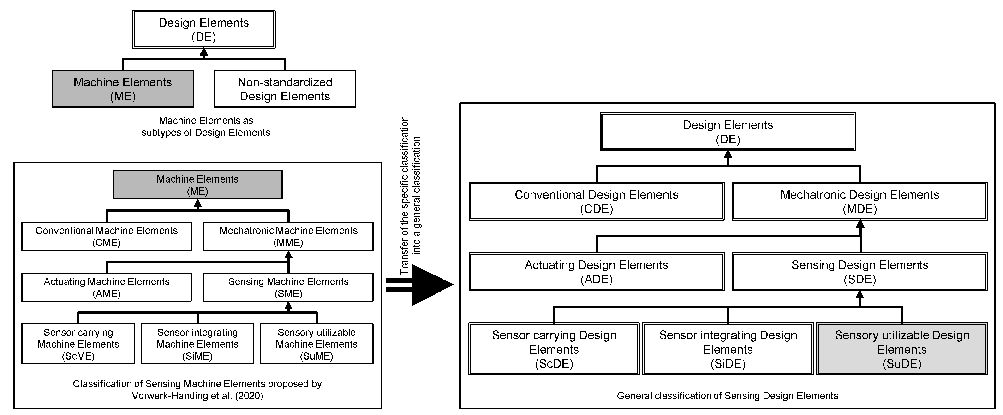
When leaving the notion of machine elements with their standards behind, one needs to think in terms of general design elements, which in turn include machine elements as a sub-group [
9], c.f.
Figure 1. Design elements as single components do not need to follow commonly accepted norms, even though they are accessible to a dimensioning calculus, e.g., shafts. Additionally, similar to machine elements it is also possible to add additional mechatronic or sensory functions to design elements [
10]. Hence, it is possible to expand the definition made by Vorwerk-Handing et al. to all design elements, as shown in
Figure 1. This definition allows the expansion of methodical approaches developed for the design of and with sensing machine elements to all design elements in general, widening the pool of possible solutions for the integration of sensory functions in technical systems. Similar to sensing machine elements, it is possible to define “Sensing Design Elements” (SDE) with its subgroups “Sensor carrying Design Elements” (ScDE), “Sensor integrating Design Elements” (SiDE) and “Sensory utilizable Design Elements” (SuDE). ScDE are design elements with an additional sensor element. The variable of interest of the sensor is unrelated to the mechanical function of the design element, for example, the temperature measurement on a gearbox housing. SiDE also have an additional sensor element, but the variable of interest has a relationship with the mechanical function of the design element, for example, the load measurement on a gearbox housing using a strain gauge. SuDE have no additional sensor elements but their electrical properties are used for sensory functions, for example, the change in electrical impedance of a spring in relation to the spring deflection. While the concepts of ScDE and SiDE outside of the usage in machine elements simply lead to standard sensory solutions, in many cases with high technology readiness levels, such as strain gauges on important components or thermocouples within the reaction zone, the expansion of the concept of sensory utilizable machine elements to SuDE can lead to novel solutions. By utilizing a design element that is directly involved in or close to the relevant process as a sensor, it is possible to measure in situ data without adding a dedicated sensor to the system [
10]. Therefore, this work is focused on SuDE. An example of a SuDE, which is not also a sensory utilizable machine element, is the sensory utilizable valve closing body, further described in
Section 2.4.
1.2. Trade Off between Standardized Measuring Components and Single-Purpose Measuring Systems
To understand the benefits arising from the use of SuDEs, the common approach to implement sensors in technical systems has to be discussed. State-of-the-art sensors are standardized components for a specific measurement of a variable of interest. An overview on measuring principles and possible sensors can be found in [
5]. Hence, the sensor has several possible applications, and its design is driven by the demand for versatile utilization, which leads to a standardized geometry. Due to this standardized geometry, such sensors are mostly implemented either in applications, which are specifically designed for the implementation of those sensors, or offer the necessary installation space (e.g., test rigs). Otherwise, the sensors are positioned distantly from the source of the desired variable of interest and a substitutional variable is measured (e.g., measuring motor current for torque estimation) [
6]. Since the data quality of sensors increases with the proximity to the source of the desired variable of interest [
11], it is often not an option to place the sensors far away from the source of its signal. Unfortunately, the available installation space in technical systems is often insufficient for the application of standardized sensors. This increases the complexity of the sensor integration, especially in retrofit applications.
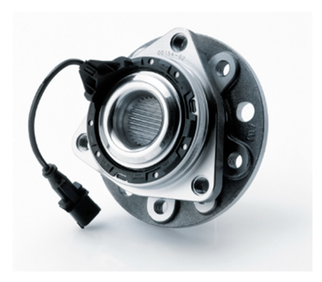
Therefore, the majority of sensing components, especially in the automotive industry, are designed and optimized for a single specific purpose at a specific built-in location [
12]. The wheel bearing with an integrated ABS sensor shown in
Figure 2 is a typical example. In the automotive industry, the limited installation space and the economies of scale justify the development of package-optimized components with integrated sensory functions [
12].
SuDE are therefore the logical next step in the integration of sensing functions into technical systems. Utilizing existing design elements in a sensing way allows, on one hand, an optimal installation space-efficient application of the sensing function. Since the utilized design element itself provides the sensing function, no additional components have to be installed. On the other hand, measuring the electric properties of the design element itself allows an in situ measurement of the desired variable of interest, which can be difficult to measure otherwise.
1.3. Effect Chains as Connectors between the Variable of Interest and the Measurement Location
An important step during the sensor selection and integration process is to connect the variable of interest with a measurable variable [
14]. After setting the variable of interest as the aim of the measurement, it needs to be transferred into a proper abstraction model, which leads to a measurable variable and a corresponding measurement location [
14]. As a short example: If the aim is to detect wear in a system, the wear usually cannot be detected directly, but a substitutional variable needs to be measured. This can be a change in a force in this system, caused by a wear-dependent coefficient of friction. This leads to a challenge during the design process to connect the actual aim of the measurement with a measurable variable. To do this, it is possible to generate effect chains based on effect catalogues (similar to design catalogues with standardized solutions), as proposed by Vorwerk-Handing [
14].
Those effect chains have the integral benefit that they connect different domains with each other. This is usually necessary since a sensor is commonly a transducer, which connects the domain of the measurement with the domain of electromagnetism [
5]. The effect chains therefore can be used for two distinct purposes. On the one hand, to connect the variable of interest with a possible measurable variable which can be detected by an already existing sensor solution. On the other hand, they can lead to novel sensor solutions by utilizing the system’s inherent physical properties to connect the variable of interest with the domain of electromagnetism [
10,
14].
For this paper, two commonly used elementary measurement effects in the domain of electromagnetism are variable resistance and variable capacitance, or their respective interpretation in terms of an electric model for the sensory utilizable effect of design elements. Both measurements of variable resistance and of variable capacitance are of high interest for SuDEs, since variable resistance or capacitance are often inherently created by parts moving relative to each other. For a capacitance
, this relative movement changes either the overlapping surface area
, or the thickness of the insulating layer
, which both together with the permittivity
determine the magnitude of the capacitance, as can be seen in the formula for a plate capacitor [
15],
1.4. Methodological Approaches for the Utilization of Design Elements
In order to be able to implement and realize the potential of SuDE in a technical system, SuDE must be systematically developed or selected and integrated into the overall system. The interdisciplinarity between the domains of mechanics, electronics and computing and the associated complexity must be taken into account [
16]. Product development generally uses procedure models and development methods for this purpose. However, it turns out that these are not yet described comprehensively enough for a systematic use of SuDE. In the following, exemplary procedure models and development methods will be presented and the remaining deficits will be addressed.
Established procedure models for product development are the Pahl and Beitz procedure [
17] and the standard VDI 2221 [
18] based on it. For mechatronic products, such as SuDE, further procedure models are proposed, such as VDI 2206 [
19]. All these general approaches have in common that they are not specifically adapted for the system to be developed in order to maintain their general validity. For this reason, the approaches mentioned can only support the specific, interdisciplinary development of new SuDE solutions to a limited extent. Necessary procedure steps such as the determination of sensor requirements, the identification of potential sensor components, their development and the subsequent integration—together with the necessary signal transmission and energy supply—are currently not yet clearly classified in the steps of procedure models.
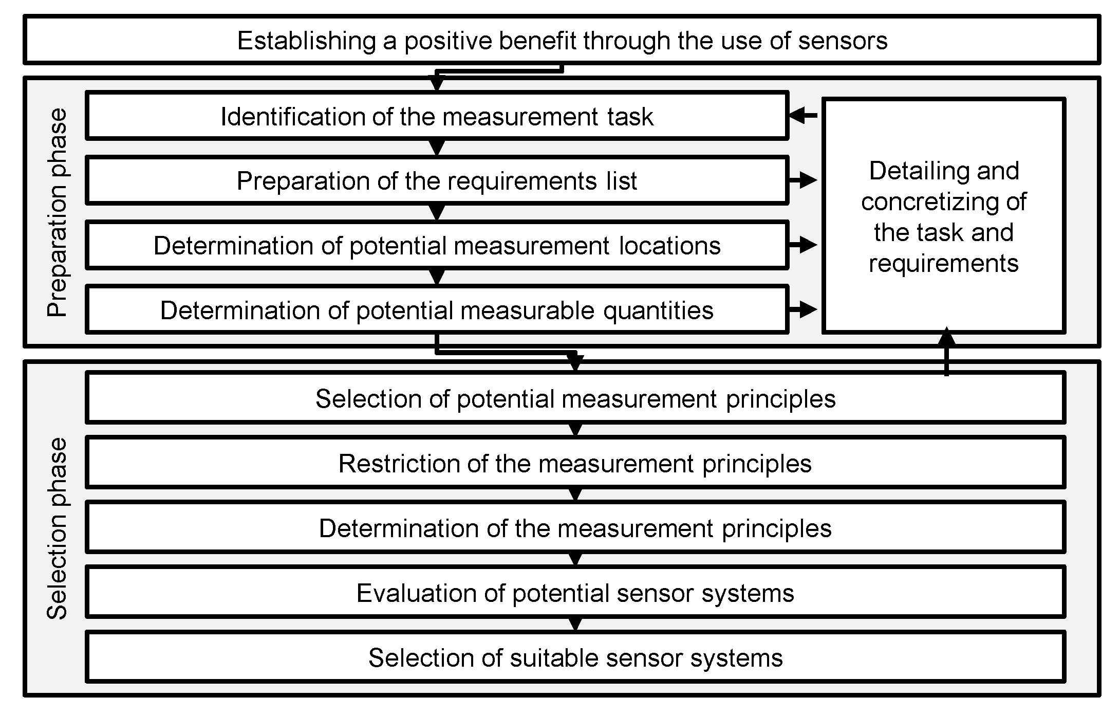
However, procedure models for sensor selection within product development can already be found in the literature. Based on the work of Eversheim and Hausmann [
20,
21], Classe [
22] proposes a procedure for a systematic sensor selection, which is further extended by Zeller [
23], as shown in
Figure 3. However, the described approaches only range from the definition of the measurement task to an evaluated selection of possible sensor solutions. The VDMA’s guide to sensor selection follows a different approach [
24]. It asks the product developer a defined number of questions to guide through the sensor selection process. To answer these questions, several catalogues with prepared solutions are offered. A new development of sensors, as well as the necessary integration of these into the overall system, is not described. Likewise, the sensory use of non-standardized design elements that are not included in manufacturer catalogs is not considered.
In addition to the described selection of existing sensors in the product development process of a technical system, the new development of sensors and SuDE represents a further challenge. In most cases the development of conventional sensors takes place before the actual development of the system, as sensors are often considered as purchased parts [
26]. When using SuDE, however, this can change. In this case, the components are first designed mechanically before a sensory function can be integrated. The development of new SuDE therefore usually takes place during the development of the system. This inevitably raises questions about potential measurement quantities, measurement principles and measurement locations. For these questions, further methodological tools are needed. An exemplary approach for the systematic identification of measurable quantities and measuring principles is described by Vorwerk-Handing [
14]. With the help of a catalogue system, physical cause–effect chains can be developed. Finally, potential measurable quantities and measuring principles can be derived from these effect chains. In addition, Vogel presents an exemplary approach with which a suitable measurement location in the system or component can be found for a selected measurable quantity. For this purpose, he extends the Contact and Channel Approach [
27] to the Load Path and Node Model [
28]. The described approaches of Vorwerk-Handing and Vogel can be applied in the context of identifying components that can be used as sensors, but they only represent a part of the required methodological tools. Methodological tools for the integration and implementation of signal transmission, as well as energy supply, have not yet been described in the literature.
2. Examples of Sensory Utilizable Design Elements
The following section shows a selection of exemplary concepts of SuDE, which were identified through a scoping review. Besides the description of the effect chains utilized in the presented examples, one aim of this section is to evaluate the methodical approach used in the development of those examples. Furthermore, remaining challenges, for example in energy supply and data transmission, will be addressed. These review results serve as basis for chapter 3, where the potentials of SuDE and existing technical and methodical challenges are highlighted, which form the basis for further research in this field.
2.1. Sensory Utilizable Rolling Element Bearing
A first sensory utilizable rolling bearing is presented by Bethke [
29]. He shows the possibility of measuring the lubrication film thickness of the bearing in applications such as grinding spindles via its capacity. Schirra uses a similar approach and developed a concept of rolling element bearings, which are used for the measurement of the bearing load condition [
30]. The development of this sensing principle is less driven by a methodical development process, and can therefore be categorized as a need–solution pair [
31]. Schirra transferred the electrical modeling of rolling bearings presented in the context of electric bearing damages [
32,
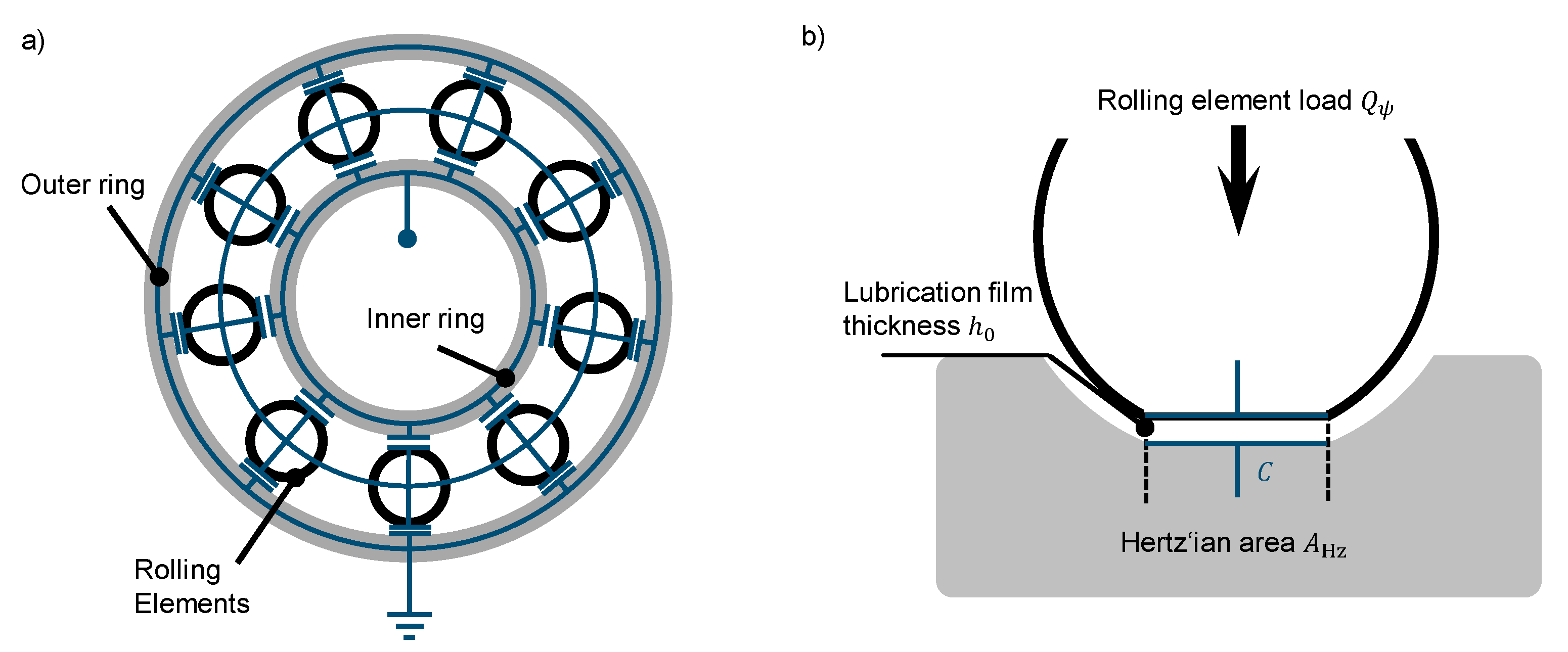
33] for sensory utilization. Operated in elasto-hydrodynamic lubrication condition, the rolling contacts inside the bearing can be described as a network of electric capacitors, as shown in
Figure 4a [
34]. The capacity
of each of the capacitors can be calculated as
where
is the area of the Hertz’ian contact between the rolling elements and
is the mean lubrication film thickness. The electric permittivity of the lubricant in the contact area is
(
Figure 4b) [
32]. The Hertz’ian contact area is a function of the bearing load, and the lubrication film thickness is a function of the bearing load and the rotation speed according to Hamrock and Dowson [
35]. Therefore, the measurement of the bearing capacity allows the extraction of different information on the bearing operation condition.
For improving the calculation of the bearing load, Equation (2) is expanded for taking into account the capacity of unloaded rolling elements or the capacity of the undeformed area surrounding the Hertz’ian contact area of loaded rolling elements [
36,
37,
38,
39]. Schirra et al. compare experimental results with calculated values [
39]. They show that the measuring offset is better than in previous calculations, but conclude that the difference between calculation and measurement is still insufficient, and the model needs further improvement to be viable for force measurement.
Figure 4.
(
a) Rolling bearing as a capacitor network; (
b) Hertz’ian contact area modeled as an electric capacitance, c.f. [
30,
39].
Figure 4.
(
a) Rolling bearing as a capacitor network; (
b) Hertz’ian contact area modeled as an electric capacitance, c.f. [
30,
39].
Additionally, it is possible to derive the rotational speed from the measured data using Fast Fourier Transformations and an order analysis scheme [
30]. Furthermore, Martin showed that statistical analysis of the impedance recorded with high frequency can yield information about the size and location of surface deviations [
40]. Pittings on the inner and outer race track cause well-determinable deviation patterns and allow for the estimation of pitting size based on the impedance measurement.
The electric input signal used for the measurement is applied by an external signal generator and the output signals are measured with an external digital oscilloscope. The electric signal applied on the bearing has to consider current density thresholds, which enable bearing damages. Electric discharges can occur at a bearing current density above
[
41] and white etching cracks occur at
[
42]. Electric bearing damages as a result of the sensory utilization of rolling element bearings were not observed.
2.2. Sensory Utilizable Hydrodynamic Journal Bearings
In the 1980s, several approaches were developed to use the electric properties of journal bearings for measuring the lubrication film thickness in the bearings of combustion engine test rigs. Filowitz et al. showed an approach to measure the lubrication film thickness by applying a constant electric potential between bearing and shaft. Therefore, the relative amount of time in which the lubrication film is below the discharge threshold defined by the dielectric strength of the lubricant is measured [
43]. The greater the amount of time in which a current is measureable, the thinner the lubrication film.
Spearot et al. show an approach to measure the resistance of the lubricant in the bearing (Total Resistance Technique) [
44]. By reducing the applied voltage on the bearing in comparison to Filowitz et al., it is possible to calculate the lubrication film thickness from the measured resistance. In a similar approach, the electric capacity is measured instead of the resistance of the bearing (Total Capacitance Technique), as shown in
Figure 5a [
45,
46,
47]. Spearot and Murphy [
48] compare the results of the Total Resistance Technique and the Total Capacitance Technique and conclude that the Total Capacitance Technique is superior due to the greater robustness of the technique respective to changes in temperature or cavitation. There is no clear description of the methods used in the development of these operating principles, although the publication of Spearot and Murphy [
48] implies that the development of those methods relies more on the experience of the researchers rather than on a generalizable methodical approach.
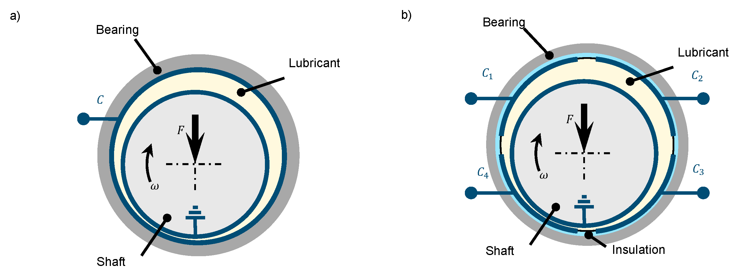
Harder and Kirchner [
49] show that due to the connection of the lubrication film thickness and the bearing load in a journal bearing, it is possible to use the principle of the Total Capacitance Technique and expand it to a load measurement. For this, an external electric signal is applied to the bearing and measured with an external oscilloscope. In addition, Harder and Kirchner address several uncertainties in the operating principle, e.g., the geometric imperfection of bearing and shaft, the misalignment of bearing and shaft, the electric properties of the lubricant, and the local change respective to temperature or pressure or the effect of additives and particles on the measurement [
49]. They conclude that a single capacitor is not sufficient for reliable load measurement, and has to be expanded to a network of several capacitors inside a bearing. Similar capacitor networks (c.f.
Figure 5b) are called cylindrical capacitive sensors and have already been described in several publications of Jeon et al. and Ahn et al. [
50,
51,
52]. By the orientation of several capacitor pairs in opposite positions (e.g., Capacitor C1 and C3 in
Figure 5b), it is possible to use a cylindrical capacitive sensor similar to differential capacitive sensors.
Figure 5.
(
a) Hydrodynamic journal bearing with contacted bearing modeled as a cylindrical capacitor; (
b) hydrodynamic journal bearing with four capacitors separated by an insulation (cf. [
51]).
Figure 5.
(
a) Hydrodynamic journal bearing with contacted bearing modeled as a cylindrical capacitor; (
b) hydrodynamic journal bearing with four capacitors separated by an insulation (cf. [
51]).
2.3. Sensory Utilizable Self-Lubricating Sliding Bearings
The utilization of the electric properties of self-lubricating fiber-composite sliding bearings is developed with the design approach of Vorwerk-Handing [
14] (described in
Section 1.4) as an initial validation for this approach [
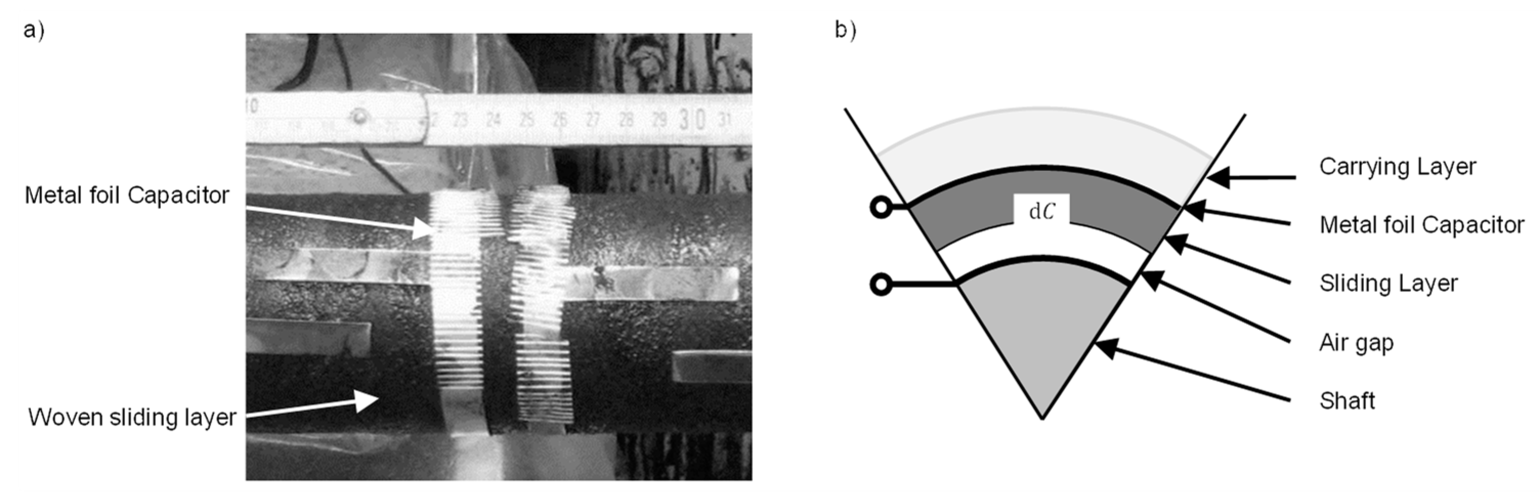
53]. During the manufacturing process of the sliding bearing, a metal foil is added between the sliding and the carrying layer of the bearing (
Figure 6a). This layer and the shaft inside the bearing can be described as an electric capacitor with the sliding layer and the air gap in-between as its two dielectrics (
Figure 6b). Measuring the capacity can offer information on the sliding layer height of the bearing. Since the sliding layer is abraded during the lifetime of the bearing, this can give the user information on the remaining useful lifetime (RUL) and can therefore be used for condition monitoring. The measurements with the developed prototype show a comparable behavior to the calculated values, and the offset is explained with parallel capacities, which are not taken into account in the evaluation model [
53].
A similar operating concept is already in serial production by igus [
54]. The sliding bearing is printed with a multi-material 3D printer integrating a conductive layer in the polymeric bearing. Depending on the position of the conductive layer, it is possible either to determine the RUL of the bearing (conductive layer is positioned on the sliding surface) or to detect possible overload (conductive layer is positioned inside the bearing).
Figure 6.
(
a) Added metal foils as cylindrical capacitors during the manufacturing process of the sensorial sliding bearing prototypes; (
b) infinitesimal element of the capacitor
C; both by [
53].
Figure 6.
(
a) Added metal foils as cylindrical capacitors during the manufacturing process of the sensorial sliding bearing prototypes; (
b) infinitesimal element of the capacitor
C; both by [
53].
2.4. Sensory Utilizable Valve Closing Body
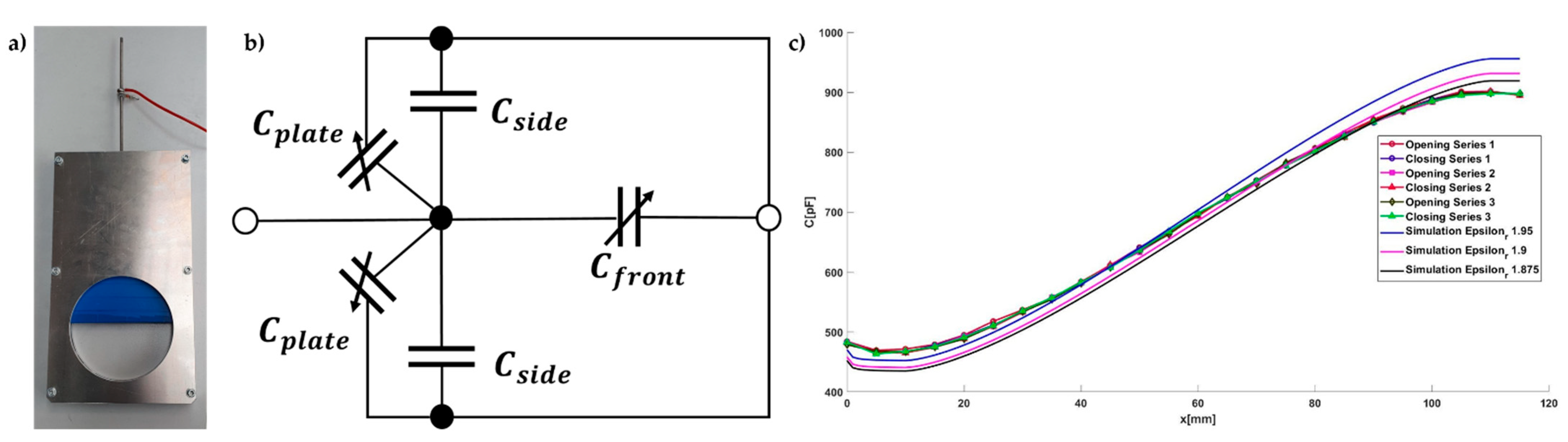
Another example for a SuDE is the utilization of a valve closing body, presented by Kraus et al. [
10]. The principle is based on a plate capacitor with a variable surface area between the housing and the closing body. The closing body of a prototype valve is coated with a non-conductive layer, which functions as the dielectric material for a plate capacitor. The measurements were taken on a prototype derived from sliding valves by reducing it to the function of opening and closing.
Figure 7a shows the used prototype and
Figure 7b the resulting electrical circuit. The surface area is divided into several plate capacitors with changing (
) or constant (
) values. The capacitance changes with the opening degree. Kraus et al. [
10] showed that the measured data of the capacitance closely follow their proposed model, with deviations close to the fully closed and opened state, as shown in
Figure 7c.
In the current development state an LCR-Bridge is used to measure the capacitance, which does not present a feasible solution for future infield applications. Additionally, possible influences such as the changing resistivity of materials commonly used in electronics in a cryo-field application [
55] need to be considered in the next steps. The graph is in most parts reversible and can therefore be used to determine the current opening degree of the valve. Further research regarding the boundary influences and an infield application is still ongoing.
2.5. Sensory Utilizable Coil Spring
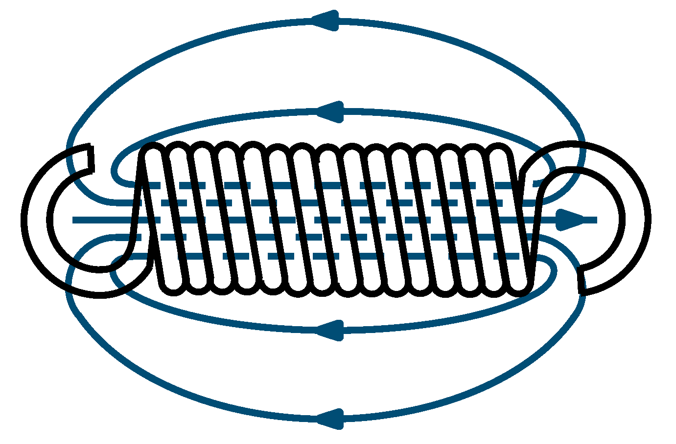
The utilization of coil springs as displacement sensors is presented by Hongjip Kim et al. and by Zur and Wießner [
56,
57]. The coil spring is herein modeled as the inductance of a solenoid coil (c.f.
Figure 8). An increase in the displacement of the coil spring leads to a higher pitch of the spring, lowering its inductance. Therefore, the coil spring can be classified as a SuDE. While Zur and Wießner describe the simulation of the spring inductance [
57], Hongjip Kim et al. present experimental results and the setup with which these results are obtained [
56]. The inductance measurement circuit and its design specifically developed for this application are presented.
Van der Weijde et al. describe an in-detail modeling of the inductance of the coil spring [
58]. Although the presented calculation considers effects such as the inhomogeneous magnetic field distribution or the helical design of the coil, a fitted model shows the best results in comparison with the measured values. Van der Weijde et al. proposed to use a linear spring characteristic to enhance the spring to a force sensor. In a later paper, Van der Weijde et al. concluded that sensory utilized coil springs can be compared with conventional direct force sensing applications in terms of sensing results, even for dynamic measurements [
59]. A comparison between inductance and the resistance measurement shows that, in comparison with an inductance measurement, the resistance measurement has a much more ambiguous relationship with the deflection of the coil spring [
60]. In contrast to the measurements of Kim et al., van der Weijde et al. did not develop a measuring device, but used an LCR Meter for measuring. Van der Weijde addressed in his conclusion the necessity of a practical measuring method. In addition, the effect of the design parameters and properties, as well as the impact of possible uncertainties, has to be investigated [
60].
Although the design and development process of the sensory utilizable coil spring is described in none of the presented sources, the conclusion by Van der Weijde shows that a systematic design methodology could benefit the development process.
3. Discussion
In the previous section, concepts were presented on how design elements can be utilized to implement a sensory function in mechatronic systems by using their electrical properties. Physical effects, caused by the variable of interest or a suitable equivalent quantity, influence the electrical properties such as resistance or capacitance in a metrological detectable range [
5]. These changes in the electrical properties are recorded and traced back to the variable of interest by an underlying physical model. Thereby, the described SuDE essentially resembles the same internal structure as conventional sensor elements. The potentials of a broad use of SuDE and the remaining challenges, which must be solved in the course of further research, will be discussed in this section. The main focus is hereby on the following key potentials and challenges:
An essential potential for the use of the presented SuDE is the relatively
simple integration into existing and newly developed technical systems. Due to the lack of additional sensory elements, the additional space required is kept within limits. On the other hand, a weakening of the mechanical elements can be avoided or kept to a minimum if only their electrical properties are used for sensory functions and no additional sensor elements have to be integrated [
9]. However, potentially damaging electrical effects from the sensory use on the design element must be considered. Nevertheless, the use of SuDE promises potential not only for the integration of sensory functions into new products, but also for the integration into existing products, so-called retrofit solutions [
14]. In addition to the potentials, open challenges have to be addressed as well. Some adaptions are still required for a successful system integration, such as the isolation of parasitic currents, the realization of a defined and clear current path, and the integration of electrical contacts. This is not only necessary to ensure a robust measurement, but also to prevent harmful currents in other design elements or create a potential risk for the user. However, these adaptions have to be kept to a minimum to reduce the integration effort, but also have to ensure a low level of uncertainty and therefore still require further research [
6].
Further potential is provided by the possibility of moving the
measurement location deep into the technical system by using SuDE in an in situ measurement location. In this way, the variable of interest is recorded as close as possible to the place of its initial occurrence. Thus, the model complexity of the transfer path of the variable of interest to the SuDE and the effects of disturbance variables can be minimized [
5]. On the other hand, there are remaining challenges of placing further required measuring equipment outside the SuDE and the technical system to ensure a stable energy supply to the SuDE, as well as a stable data transmission from the SuDE.
As mentioned, the use of SuDE also requires a sufficient and stable
energy supply and
data transmission. Initially, it must be clarified which form of electrical energy supply, alternating or direct current, and data transmission, analog or digital, is required for the SuDE. One solution is to simply add cables to supply the sensory utilizable design element with energy and transmit the measurement signal. While this might seem trivial, it often comes with the drawback of necessary sliding contacts for connecting elements mounted on moving or rotating parts, which lead to wear in the transmission path and noise in the measurement signal [
61]. Another proposed solution is to use the design elements of a technical system themselves as electrical conductors. While this seems to solve some problems, new challenges arise at the same time that need to be solved in further research. For example, the use of high-frequency carrier signals, as described in the example of the sensory utilizable roller bearing. The high frequencies used are associated with potentially disturbing electrical influences, such as the skin effect, and must therefore be controlled by suitable models or avoided by other measurement approaches with lower frequencies. In the examples presented in this contribution, which are taken from current scientific research and are usually developed on specific test benches, suitable solutions for field applications are often missing.
A fundamental challenge is the identification and utilization of the underlying physical effects in SuDE. In order to obtain qualitative and quantitative precise information from the measurement, the effects must be described by
models that are as accurate as possible with a low level of uncertainty. In this context, besides the model uncertainty, the uncertainty caused by disturbance variables also has to be taken into account [
14]. For this reason, the model descriptions must be able to capture and describe all relevant disturbance variables. In technical systems, this includes, for example, the influence of loads, speeds or temperatures, but also the influences of electrical parameters such as voltage, frequency and electrical fields. In the case of the sensory use of a rolling bearing, valid model descriptions are currently subject to research in order to be able to calculate and interpret the measured impedance [
39].
From a product development point of view, suitable
development methods are also needed and still missing for the systematic development, selection and integration of sensory functions into design elements. As presented in
Section 1.4, it can be summarized that the existing procedure models for product development, as well as for sensor selection and development methods, are not yet sufficient to systematically expand design elements with a sensory function. The examples presented in
Section 2 give a similar conclusion. Most of the examples do not mention a methodical approach used in the development process and it can be assumed that the described concepts were found either through engineering experience or as a result of a need–solution pair. There is a lack of clear description of the necessary procedure steps, from the determination of sensor requirements to the actual integration of the design element into the system with the associated signal transmission and energy supply. These steps still need to be integrated into the product development process of the overall technical system.
4. Conclusions
The intention of this contribution is to provide an overview of the sensory use of design elements. For this purpose, sensing design elements are classified based on the established classification of sensing machine elements, whereby the focus of this paper is on sensory utilizable design elements, as these have not yet been developed systematically and necessary research gaps can be identified. Therefore, the motivation for measuring as close to the process as possible in the context of the continuous digitalization is highlighted. For these, promising examples from current research are presented, whereby the potentials of these new solutions are shown and remaining challenges are derived.
Potentials can primarily be derived from the ability to place SuDE directly into the system without the need for complex design adaptations. No specific sensor modules are required, as the electrical properties of the design element are used directly for the sensory function. In this way, developed sensor concepts can be generalized, which makes it possible to transfer them to other technical systems.
Open challenges and thus further research areas include the development of usable models for the underlying physical effects that allow the electrical properties of design elements to be used for sensory applications. Furthermore, challenges of a sufficient energy supply and signal transmission must be solved. Systematic approaches, such as suitable methods, are needed for these tasks in order to make development more effective and efficient. The open challenges must first be addressed in further research before the practical suitability of SuDE can be demonstrated beyond operation on test benches

 ,
, 


