Abstract
Electronic devices and their associated sensors are exposed to increasing mechanical, thermal and chemical stress in modern applications. In many areas of application, the electronics are completely encapsulated with thermosets in a single process step using injection molding technology, especially with epoxy molding compounds (EMC). The implementation of the connection of complete systems for electrical access through a thermoset encapsulation is of particular importance. In practice, metal pin contacts are used for this purpose, which are encapsulated together with the complete system in a single injection molding process step. However, this procedure contains challenges because the interface between the metallic pins and the plastic represents a weak point for reliability. In order to investigate the reliability of the interface, in this study, metallic pin contacts made of copper-nickel-tin alloy (CuNiSn) and bronze (CuSn6) are encapsulated with standard EMC materials. The metal surfaces made of CuNiSn are further coated with silver (Ag) and tin (Sn). An injection molding tool to produce test specimens is designed and manufactured according to the design rules of EMC processing. The reliability of the metal-plastic interfaces are investigated by means of shear and leak tests. The results of the investigations show that the reliability of the metal-plastic joints can be increased by using different material combinations.
1. Introduction
In recent years, electronic applications have increased significantly due to developments in more sophisticated electronics. The number of electronic systems and their components is directly related to current trends, including ongoing digitalization [1], miniaturization [2], electro mobility [3,4] and sustainability [5]. Due to the large number of new applications, the speed of development is increasing rapidly, so that innovation times for more powerful components are required to be shortened. Additionally, the bandwidths of signal transmission in telecommunications, data technology and automation are continuously increasing. These current trends require new materials and developments in order to cope with the increasing demands [2,3,4,5,6].
In addition, the trend in electronics development requires new material solutions for applications with increased demands on reliability, including extended temperature resistance or use in corrosive environments [7].
Furthermore, there is a need for improved product longevity, which can only be guaranteed by means of the necessary reliability of the overall electronic systems.
The reliability of an overall electronic system stands for its ability not to fail during the usage for a defined period of time under given functional and environmental conditions [8]. The occurrence of a failure is always the result of a certain failure mechanism, which is caused by certain material parameters paired with certain environmental conditions [9].
Due to the increasing requirements for an insulating and environmentally protective coating material, it can be observed that EMCs, which belong to the group of thermosets, are increasingly coming to the forefront in the electronics industry. This is mainly due to their advantageous properties, for example high thermal and chemical resistance as well as high mechanical resilience. Another reason for their use is that the subsequent product-specific properties of EMCs can be influenced by the mixing ratios of the components. This leads to the expansion of application fields and can increase the reliability of the overall systems [10].
To ensure the functionality and reliability of overall electronic systems, it is necessary to examine the probability of failure of the individual components and reduce it to a minimum [9]. One of these individual components are plugs, which are required, for example, for the electrical coupling of the overall systems with external sources. The design of the connectors is realized, for example, with a metallic connector contact and a plastic for the insulation [11].
Over molding of metallic connector contacts by means of injection molding enables the production of highly integrated electronic systems with an economical and innovative process. In the context of insert molding, the term hybrid technology has become established. A hybrid component consists of at least two different materials whose positive properties are combined to meet high demands. Hybrid plastic-metal connections, which are produced directly by the injection molding process, are becoming increasingly important in industrial production. In particular, they are used in the automotive and aerospace industries because of their low weight and the small number of manufacturing steps required to achieve the same or improved performance of the components. For a long time, their production was cost-intensive due to the separate production of plastic and metal components and the resulting process steps [12,13,14].
However, this approach brings challenges as the interface between the metallic connector contacts and the plastic is a weak point for reliability. Insufficient reliability can result in a complete failure of the entire system [12,15]. Therefore, different material pairings for a connector configuration are investigated and evaluated within the scope of the present work.
2. Materials and Methods
2.1. Basics of Epoxy Molding Compounds
Epoxy resins belong to the group of reactive resins which are liquid in their raw state, which is why various additives are usually required during processing. However, epoxy resins need to be highly modified to be processed by injection molding. Therefore, plasticizers, adhesion promoters, thinners or lubricants are added to transform the original raw material into a processable molding compound [16,17]. By mixing in the additives, EMCs can be modified and adapted to the respective application or requirement [18]. EMCs in the form of granules or pellets can be processed using transfer molding or injection molding [16,19].
2.2. Injection Molding Process
The injection molding process for thermosets is basically the same as for thermoplastics, except for a few differences. The EMC is preheated in the plasticizing unit; the temperature usually remains below 120 °C. The actual plasticization of the EMC molding compound takes place in the injection mold at a material-dependent temperature, which, however, is usually between 150 °C and 180 °C.
After the injection process, the melt enters the cavity via the sprue. The sprue length must be correctly dimensioned so that the plastic melt is heated by the injection mold temperature before entering the cavity, melted and brought to the optimum viscosity. The injection process is followed by the material-dependent curing time, within which complete curing takes place. After this time, the finished component is removed from the injection mold by means of ejector pins [20].
2.3. Metal-Polymer Composite
The contacting of complete electronic systems can be achieved, amongst others, by means of connectors, which in principle consist of two material classes, metals as the contact element and polymers as the insulation material [21]. These connectors enable the modular design of assemblies, technical devices and systems. This simplifies the replacement of components and the performance of maintenance work [11].
Due to the constantly increasing requirements in different industry sectors, a. o. automotive lightweight construction, the production of hybrid components has increased significantly [22].
For a long time, their fabrication was cost-intensive due to the separate production of metal and plastic parts and the resulting process steps. Currently, the trend is to produce such joints in a single process step using injection molding. However, this increasingly presents new challenges, especially for the production of a media-tight composite [12].
Further difficulties also arise from the issue of stress cracking due to the different properties of the materials used in composites. This is because metallic components can only be tightly over molded with polymers to a limited extent. In addition, micro-gaps or cracks can develop between the different materials due to different coefficients of thermal expansion (CTE), whereby liquid or gaseous media can creep into the interior of the component due to capillary action. This would attack the contact elements inside the encapsulation and lead to oxidation or corrosion over time [15,23,24].
2.4. Selection of EMC
Two EMC molding compounds from the companies Duresco (Witterswil, Switzerland) with the designation NU 6110V and Raschig GmbH with the designation EP 3681E were used to carry out the work. The EMC molding compounds are standard materials for electronics encapsulation and easily available in the European market.
Duresco NU 6110V is a glass fiber reinforced EMC with material properties adapted to high temperature applications. According to the technical data sheet, areas of application are the encapsulation of electrical components, for example solenoid coils or sensors [25].
Raschig EP 3681E is an EMC reinforced with glass fibers and inorganic resin carriers. According to the data sheet, it has good mechanical properties and exhibits a media-tight bond to metal surfaces. It is used, for example, for the media-tight encapsulation of pressure and stress-sensitive sensors and circuit boards, or for electronic components in the automotive industry [26].
2.5. Conception of the Metal-Polymer Composite
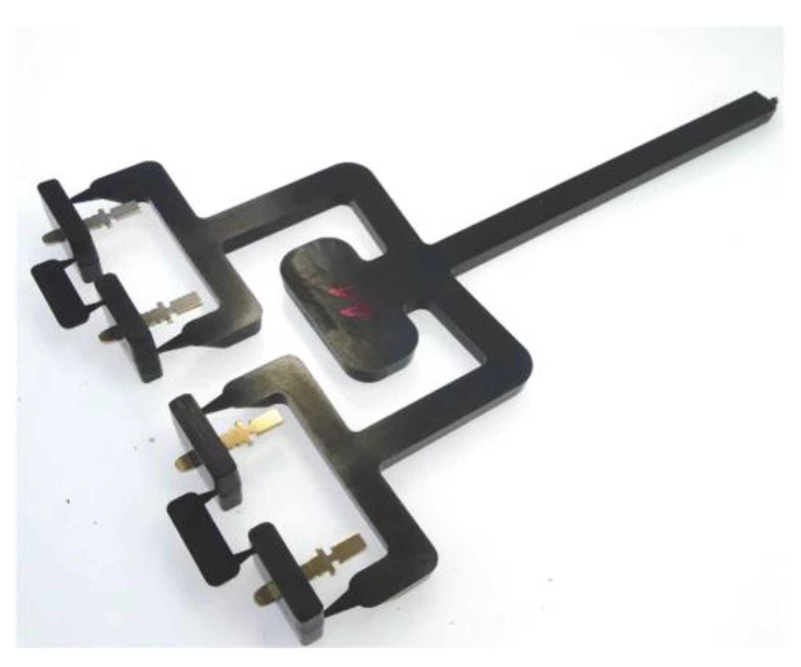
The metal-plastic composite serves as the basis for the investigations. A metallic plug contact made of a CuNiSn alloy and CuSn6 was selected for the production of the metal-plastic connections. In order to be able to investigate other metallic coatings, the plug contacts made of CuNiSn were coated with chemical Sn and chemical Ag. The coatings were selected in close discussion with representatives from the industry within a joint-project (AiF Duroconnect). The selected plug contact was produced with an existing stamping tool and is shown in Figure 1.
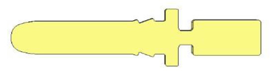
Figure 1.
Plug contact as insert.
2.6. Coating of the Plug Contacts
In order to achieve the best possible connection between the connector contacts and the coating, various pre-treatments were carried out. Based on the previous experience of the staff in the metallization group in-house at Hahn-Schickard, an intermediate layer of chemical copper (Cu) was applied to the connector contacts. Experience has shown that the intermediate layer improves the adhesion of the final layer of electro less Sn. The pre-treatment and coating of the inserts was carried out in a multi-stage process.
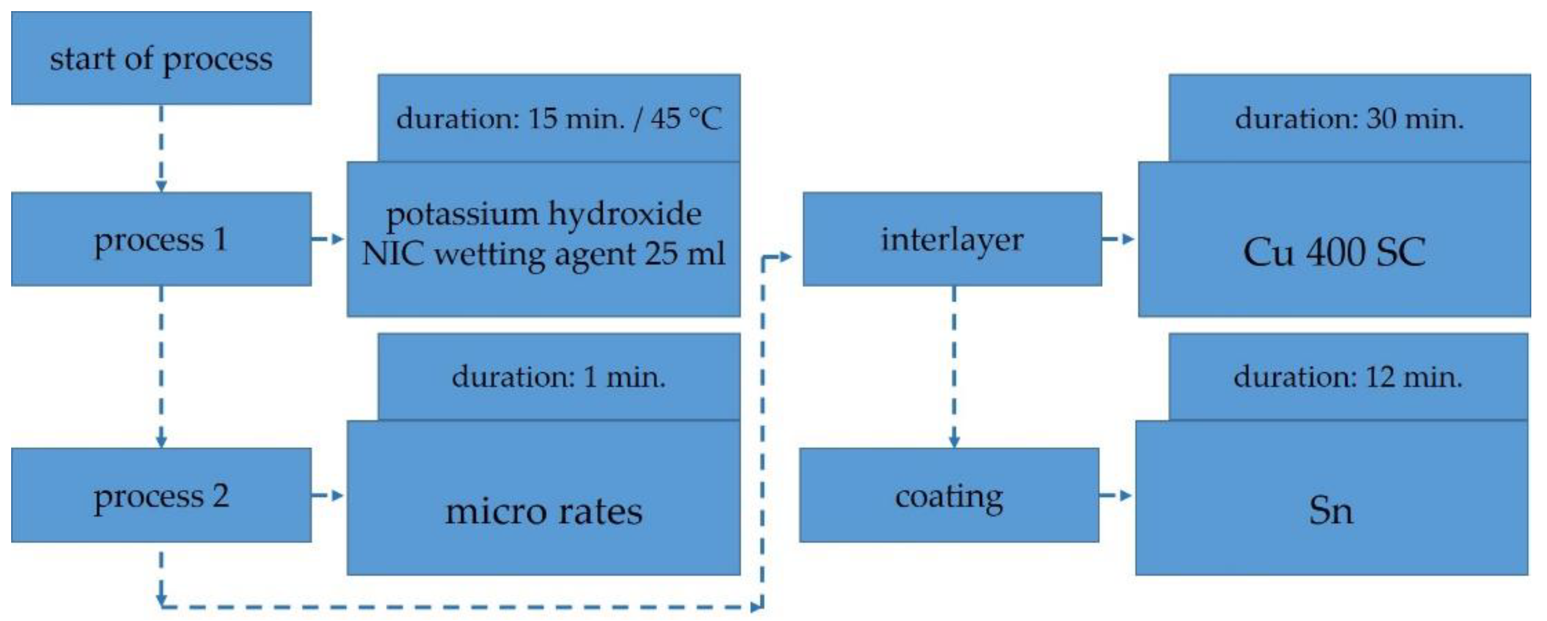
In process 1, the surface of the connector contacts was alkaline roughened in an etching solution containing a liquid mixture of potassium hydroxide (KOH) and NIC wetting agent (NIC) under a temperature of 45 C for 15 minutes. Microetching was then performed for a period of one minute; this process is used to remove the oxide layers. After completion of the pretreatments, the connector contacts were placed in a beaker containing Cu 400 SC for twenty minutes, thus obtaining an intermediate layer of chemical copper. After this process step, the plug contacts were ready for the final plating process and were coated with Sn for a duration of twelve minutes (Figure 2).
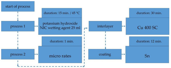
Figure 2.
Process sequence: Coating of the inserts with chemical Sn according to the experimental plan.
For quality assessment, the coated connector contacts were subjected to an adhesion test according to DIN ISO 10683, also known as the wallpaper test. In this test, an adhesive tape with a defined adhesive strength is fixed to a coated surface and pulled off in a jerky manner. The quality of the adhesion is then assessed by looking at the residue under the microscope. Visibility of the base material indicates a lack of adhesion. In addition, the coating thicknesses were measured using scanning electron microscopy (SAM) (Sonix Echo, Sonix, USA) [27].
A layer thickness measurement showed a thickness of 0.896 µm for the intermediate layer of Cu and 1.083 µm for the final layer of Sn.
Preliminary tests were also carried out in the beaker for coating the plug contacts with Ag. Due to the knowledge already gained in the course of coating with chemical Sn, fewer iterations were required for this series of tests.
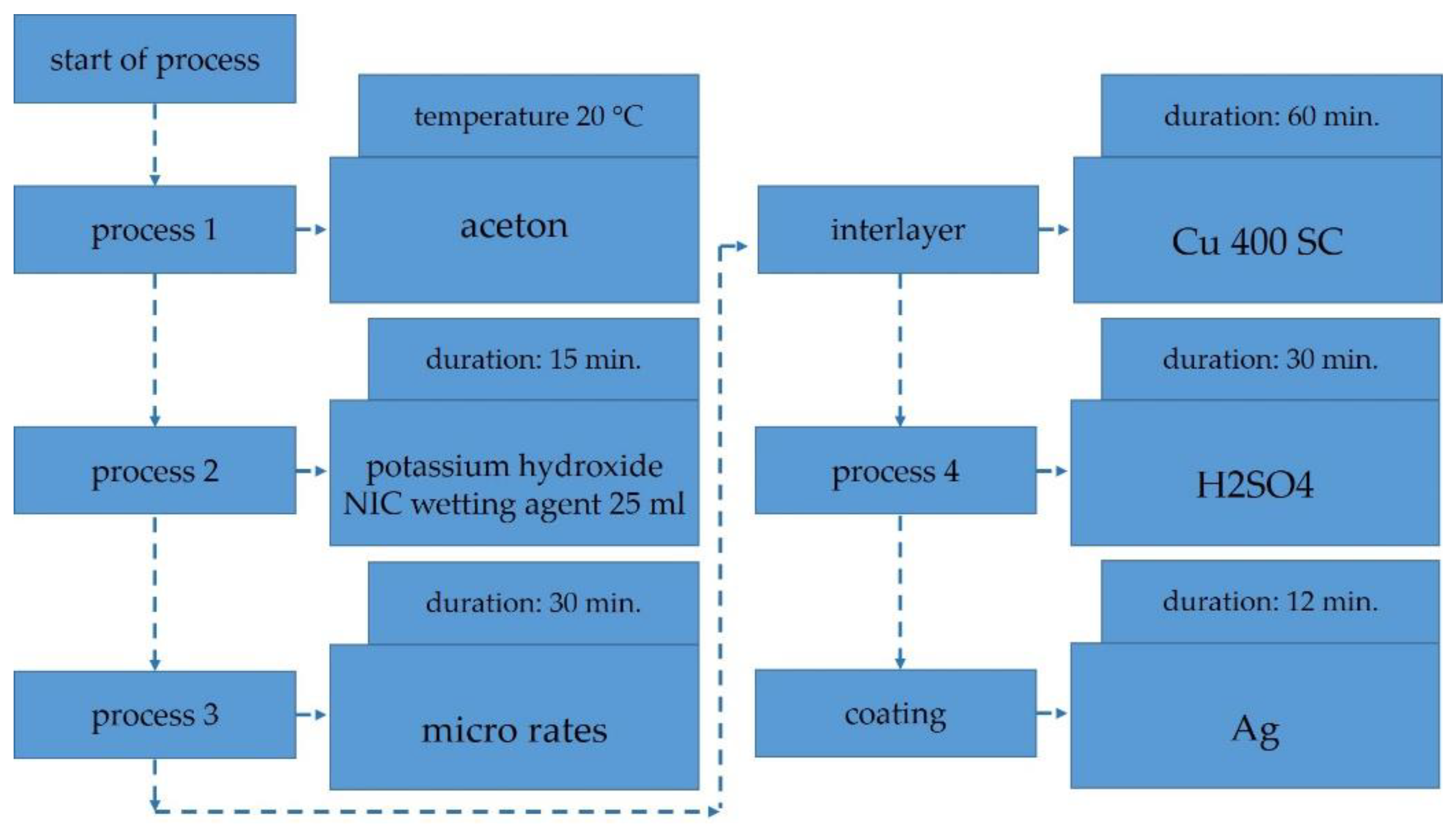
In the first pretreatment step, the connector contacts were cleaned with acetone at room temperature. Subsequently, the surface of the connector contacts was alkaline roughened in an etching solution containing a liquid mixture of KOH and NIC for 15 minutes. In pretreatment process 3, the inserts were then placed in a micro etch for 30 seconds. The first intermediate layer was then chemically applied Cu 400 SC. Prior to final Ag plating, the inserts were placed in a liquid mixture of H2SO4 for 30 seconds. Lastly, the connector contacts were placed in a Ag mixture for 12 minutes for Ag plating (Figure 3).
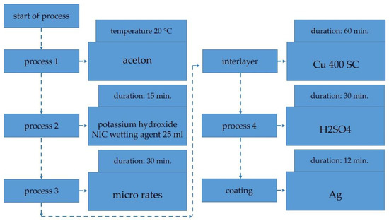
Figure 3.
Process sequence: Coating of the inserts with chemical Ag according to the experimental plan.
A layer thickness measurement showed a thickness of 0.794 µm for the intermediate layer of Cu and 1.012 µm for the final layer of Ag.
2.7. Injection Mold Design
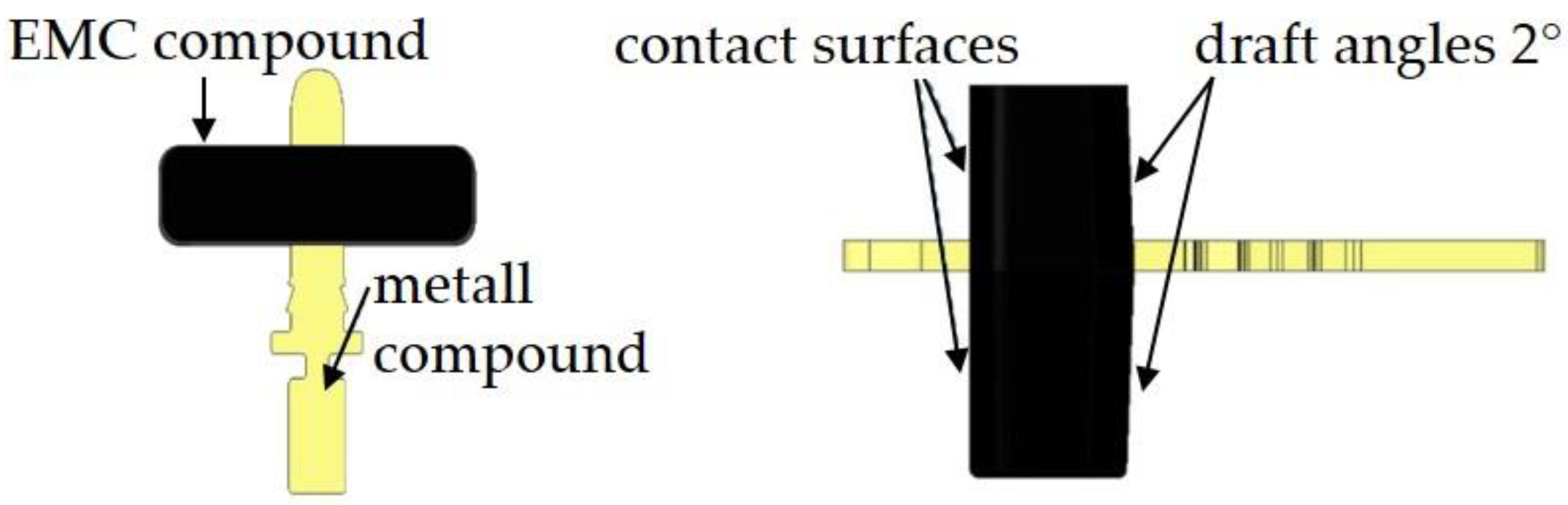
The component geometry has a draft angle of 2° (Figure 4). The design of the metal-polymer composite was carried out with the computer-aided design (CAD) software Creo 4.0.

Figure 4.
CAD component design for metal-polymer composite.
A four-cavity injection mold was designed and manufactured for the production of the metal-polymer composite. The injection mold consisted of two mold halves: an ejector side and a nozzle side. Standard parts made of tool steel 1.1730 were used to construct the injection mold. The material 1.1730 is unalloyed and is used for all simple mold components due to its good processing properties. The cavity inserts were made of tool steel 1.2379 (X153CrMoV12). This is a cold work tool steel that is characterized by high wear resistance. Due to its high chromium content, it has a low adhesion to EMCs [14]. The cavity inserts made of 1.2379 were additionally hardened after their completion. This is necessary because more wear than usual is to be expected on the injection mold due to the inserts or connector contacts and the abrasive EMCs [28]. In order to prevent smooth demolding and tilting or canting of the inserts, demolding chamfers were applied to the component geometry.
The temperature of the injection mold was controlled by two electric heating cartridges in each of the intermediate plates and four in each of the cavity inserts. In addition, the entire injection mold was covered at all boundaries with thermal insulation plates. This prevents heat loss and thus contributes to an even temperature distribution in the mold.
2.8. Process Simulation
Injection molding simulations were carried out on the basis of the design data and the existing material data. This enables the prediction of the heat distribution in the mold, the filling behavior of the mold cavity as well as the risk of air inclusions and weld lines. The simulations were carried out with the software sigmasoft. The injection mold was designed with heating cartridges with a heating capacity of 500 watts each. Figure 5 shows that a processing temperature of the EMC of at least 150 °C is reached on the mold surface. Simulations were also carried out on the filling behavior of the cavity. In addition, the figure shows the temperature of the liquid EMC mass after the injection process as well as the temperature distribution on the mold surface.
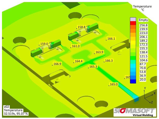
Figure 5.
Filling simulation in sigmasoft.
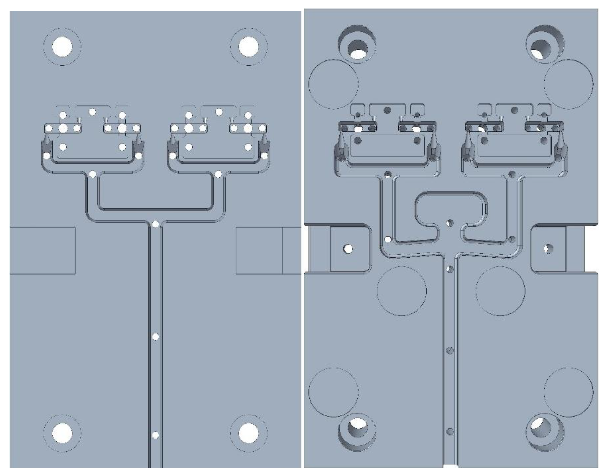
By means of the filling simulations, uneven filling behavior of the first iteration of the sprue geometry (Figure 6, left) could be identified. The balanced sprue geometry can be seen in Figure 6, right. This balancing ensures a uniform filling behavior of the individual cavities, which ensures identical processing conditions during the molding trials and is the prerequisite for a constant component quality.
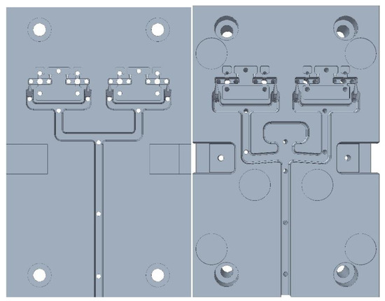
Figure 6.
Cavities, (left): 1st iteration; (right): balanced sprue geometry.
To monitor the cavity filling, an internal pressure sensor from Kistler (type 6165A) was installed in each of the two outer cavities. In addition, six circular pockets with a depth of 0.5 mm were inserted into the cavity to ensure that the mold temperature is always measured at predefined positions.
2.9. Design of Experiments
Within the scope of the investigations, a full-factorial test plan with five factors was set up. The factors EMC material, internal pressure, production pressure and temperature plug contact each have two levels. The coating factor has two additional levels. The parameters are shown in Table 1.

Table 1.
Statistical experimental design for the experimental procedure.
2.10. Mold Trials
The metal-polymer composite was fabricated on an injection molding machine from Arburg GmbH (Lossburg, Germany) (type Allrounder 375 V 500–100) with a screw diameter of 15 mm. The connector contacts were first cleaned in an ultrasonic bath with isopropanol and then inserted into an injection molding tool and then over molded.
The mold temperature was set at 180 °C and the injection speed at 2 cm3/s.
After completion of the initial test runs, the metal-polymer composite was sampled according to the test plan. The connector contacts were preheated directly in the injection mold Table 2. The sampled metal-polymer composite with the balanced sprue geometry is shown in Figure 7.
Table 2.
Process parameters for the injection molding.

Figure 7.
Metal-polymer composite.
2.11. Reliability of Metal-Polymer Connections
The reliability of a metal-polymer composite depends, among other things, on the behavior of the interfaces within the composite. Shrinkage of the EMC can improve mechanically the joint strength. Leakage is a good indicator regarding imperfections of the joint. Leakage is due to shrinkage of the respective composite materials [26].
After the metal-polymer joints have been produced, too much shrinkage of the polymer can lead to the formation of cracks. On the other hand, too little shrinkage would lead to the formation of gaps and thus to leakage. Furthermore, due to different CTEs between the different materials, micro-gaps or cracks can form, whereby liquid or gaseous media can creep into the interior of the component due capillary forces. This would attack the contact elements inside the encapsulation and lead to oxidation or corrosion over time [6].
Table 3 shows the CTEs of some materials used in electronics encapsulation. The media-tight bond between metal and plastic is required for reliability reasons, depending on the application.
Table 3.
Coefficient of thermal expansion of materials used [25,26,29,30].
2.12. Shear Test
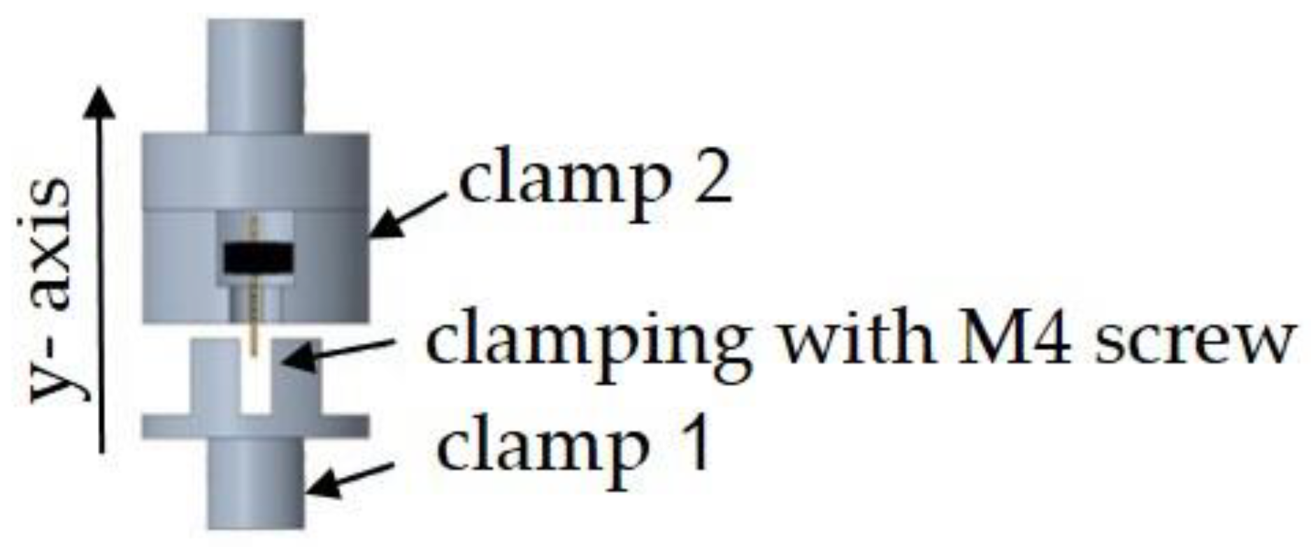
The shear strength tests were carried out on the DO-FB0.5TS tensile testing machine from Zwick Roell. For this purpose, a fixture was designed and manufactured, which is shown in Figure 8. The fixture was screwed upright into the base crosshead of the testing machine and fixed with a straight pin.
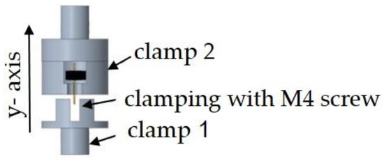
Figure 8.
Recording for carrying out the shear tests.
The metal-polymer composite in the following component was then slid into it from the front. The metal-polymer composite was fixed to the metal surface in clamp 1 by means of an M4 screw. The metal-polymer composite was not fixed in clamp 2 and was therefore loose. When the shear tests were carried out, the clamp 2 was automatically moved in the Z-direction at a predefined speed. The EMC was pulled upwards from the connector contact. To determine the shear strength (τ), the maximum tensile force (Fmax) at which the connection between the plug contact and the thermoset fails was measured. Figure 9 shows the insert with the connecting surfaces.
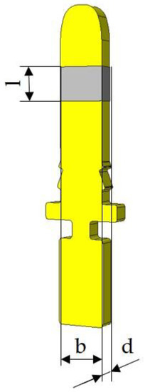
Figure 9.
Schematic drawing of encapsulated metal insert.
The fracture area (A) between EMC and connector contact is calculated as follows:
where A is the fracture area and b, l and d are dimensions of the contact area as depicted in Figure 9.
The shear strength (τaB) can then be determined from Fmax and A:
where Fmax is the applied maximal force τaB is the achieved shear strength.
2.13. Leak Test
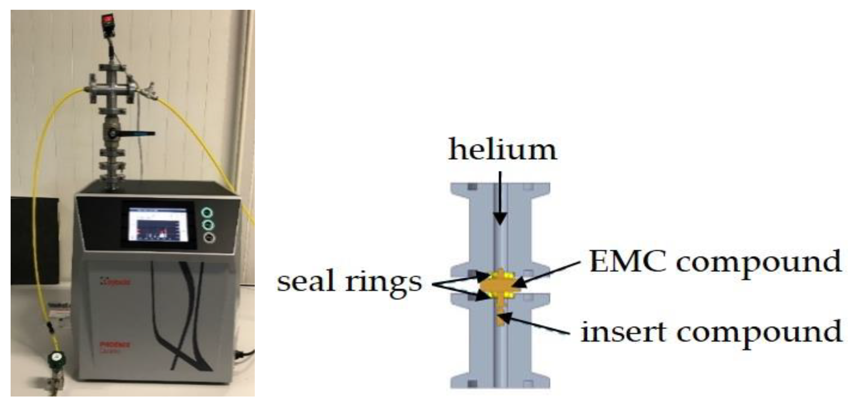
A test system from Leybold GmbH (type Phoenix Quadro) was used to carry out the leak test. The design of the mounting adapter was also carried out with the support of this company. Figure 10 shows the manufactured mounting adapters and the structure. The metal-polymer composite was installed in the parting plane of the mounting adapter, sealed with sealing rings and screwed in place. The sealing rings are intended to prevent unintentional leakage in the mounting adapter. For the evaluation of the results, the numerical values of the leakage rate were recorded and documented for up to one minute. To ensure the tightness of the assembly, a reference component without plug contact was sampled, with the help of which it was possible to check the assembly for leaks at the beginning of the measurements.
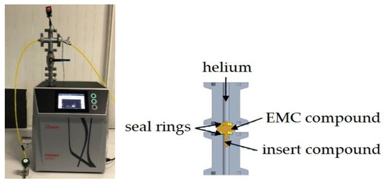
Figure 10.
Leak test with Phoenix Quadro.
2.14. Thermal Cycling
Temperature cycling is one of the most frequent causes of failure in electronic systems. Due to the different coefficients of thermal expansion (CTE) of the materials, cracks or material detachment can occur. Therefore, the metal-polymer composite was subjected to a thermal cycling test according to DIN EN 60068. The holding temperatures were −40 °C and +150 °C, the change time 10 s and the holding time 15 min per half cycle. A total of 1000 thermal cycles were carried out.
3. Results
3.1. Shear Test
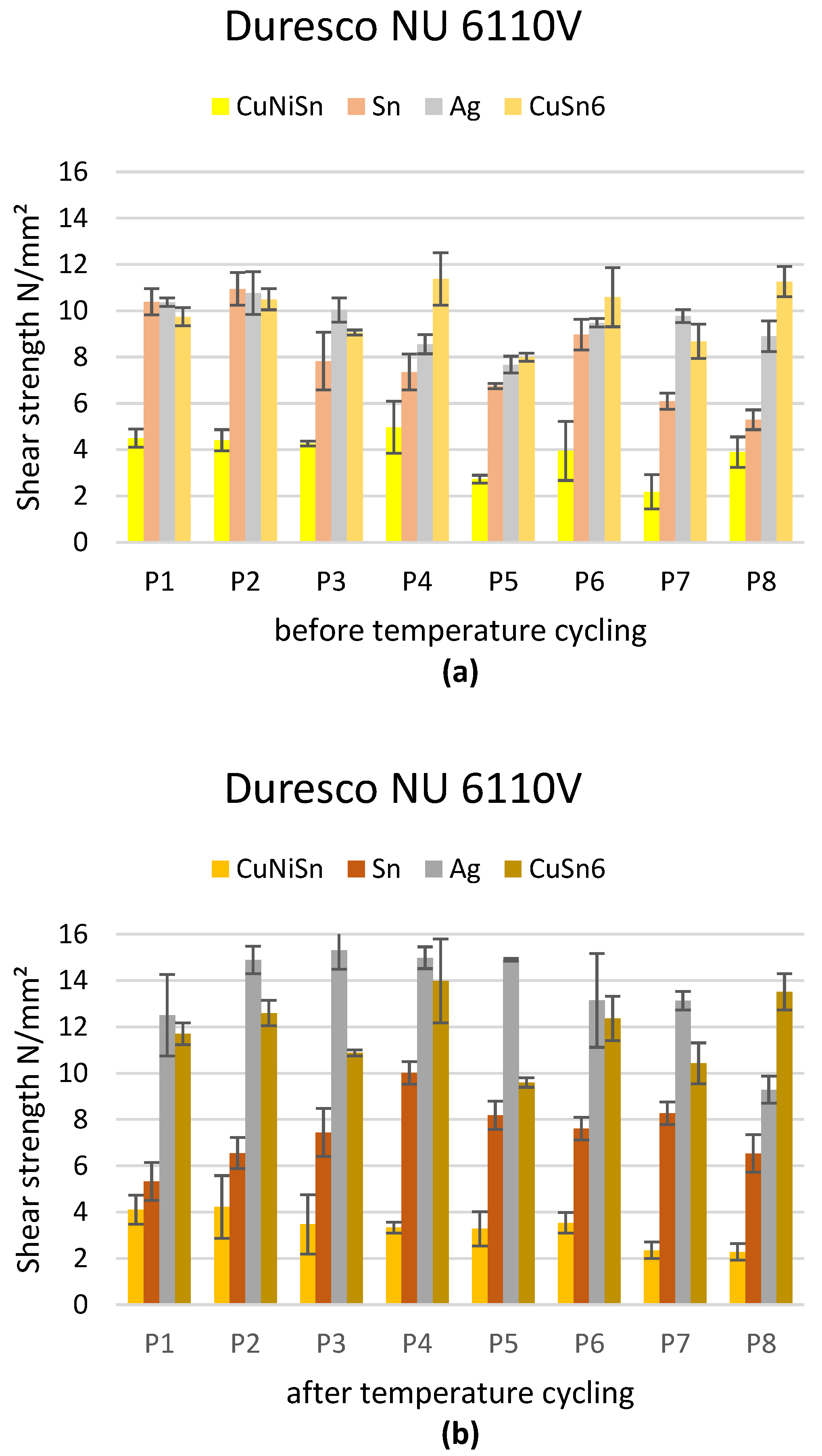
The results of the shear test before and after the temperature cycling test with the previously defined process parameter sets 1–8 are shown in Figure 11 and Figure 12.
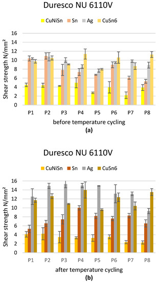
Figure 11.
Results of the shear test with Duresco NU 6110 V for the parameter sets defined in Table 2: (a) before temperature cycling; (b) after temperature cycling.
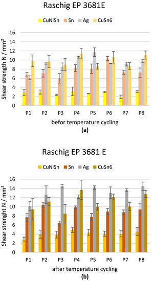
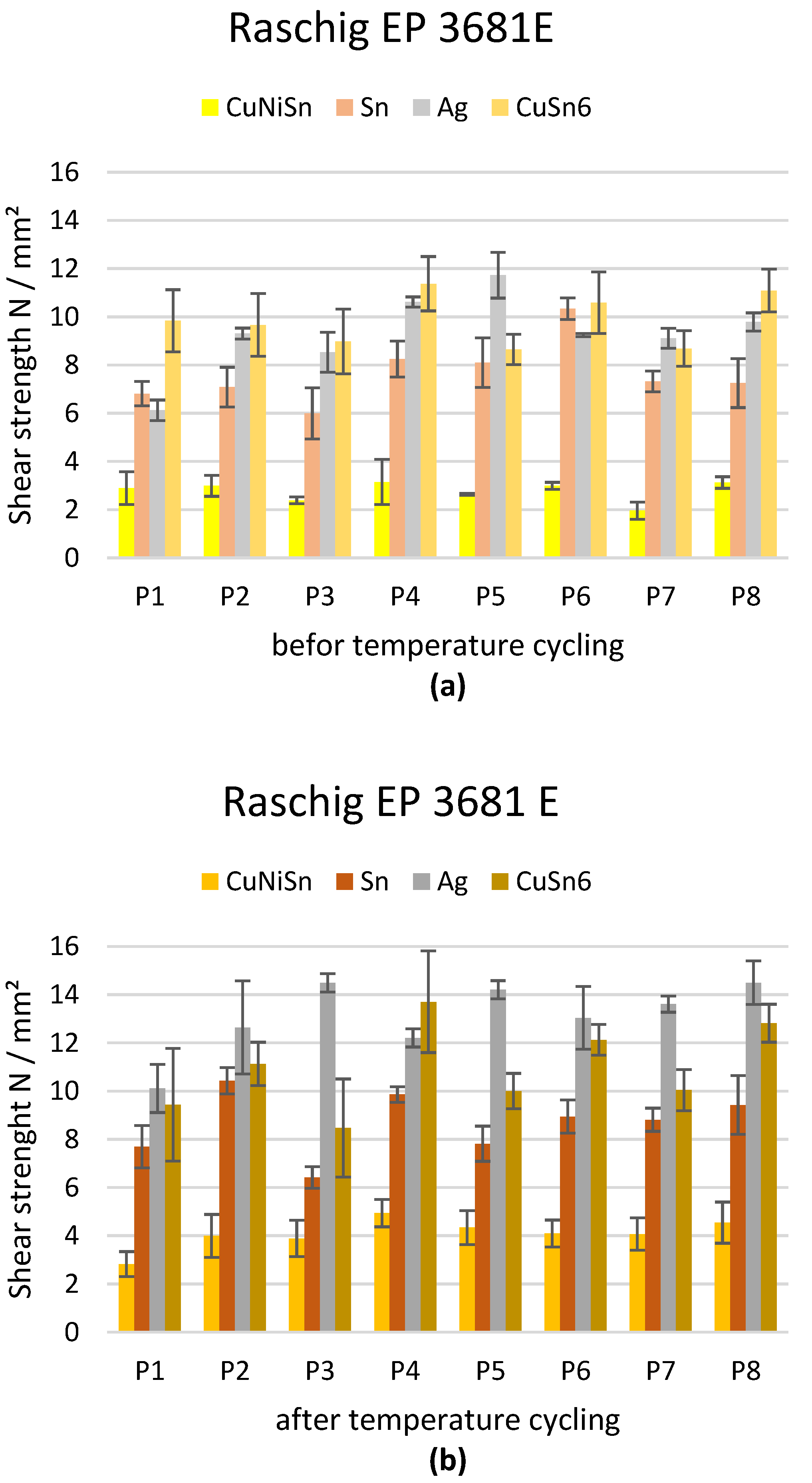
Figure 12.
Results of the shear test with Raschig EP 3681 E for the parameter sets defined in Table 2: (a) before temperature cycling; (b) after temperature cycling.
Figure 13 shows the results of the shear tests before and after the temperature cycling test for different coatings and EMC. The mean values of the individual results for the parameter sets 1–8 were considered for the evaluation. The X-axis shows the respective coatings and the Y-axis illustrates the shear strength in N/mm².
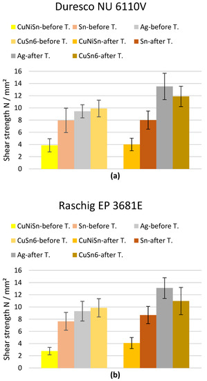
Figure 13.
Results of the shear test, with reference to the mean values for parameter sets 1–8 of the coatings: (a) before and after temperature cycling with Duresco NU 6110 V; (b) before and after temperature cycling with Raschig EP 3681 E.
It can be noted that the highest shear strength was achieved by the Ag and CuSn6 coatings. The lowest shear strength was achieved with the CuNiSn coating. The highest shear strength was achieved with parameter set 4 (high temperature plug contact, high production pressure and low internal pressure). Preheating the inserts also led to an increase in the shear strength. All test specimens showed improved shear strengths after the temperature cycling test of 1000 cycles. The increase of the shear strength tended to be higher for Ag and CuSn6 compared to the CuNiSn and Sn coatings.
3.2. Leak Test
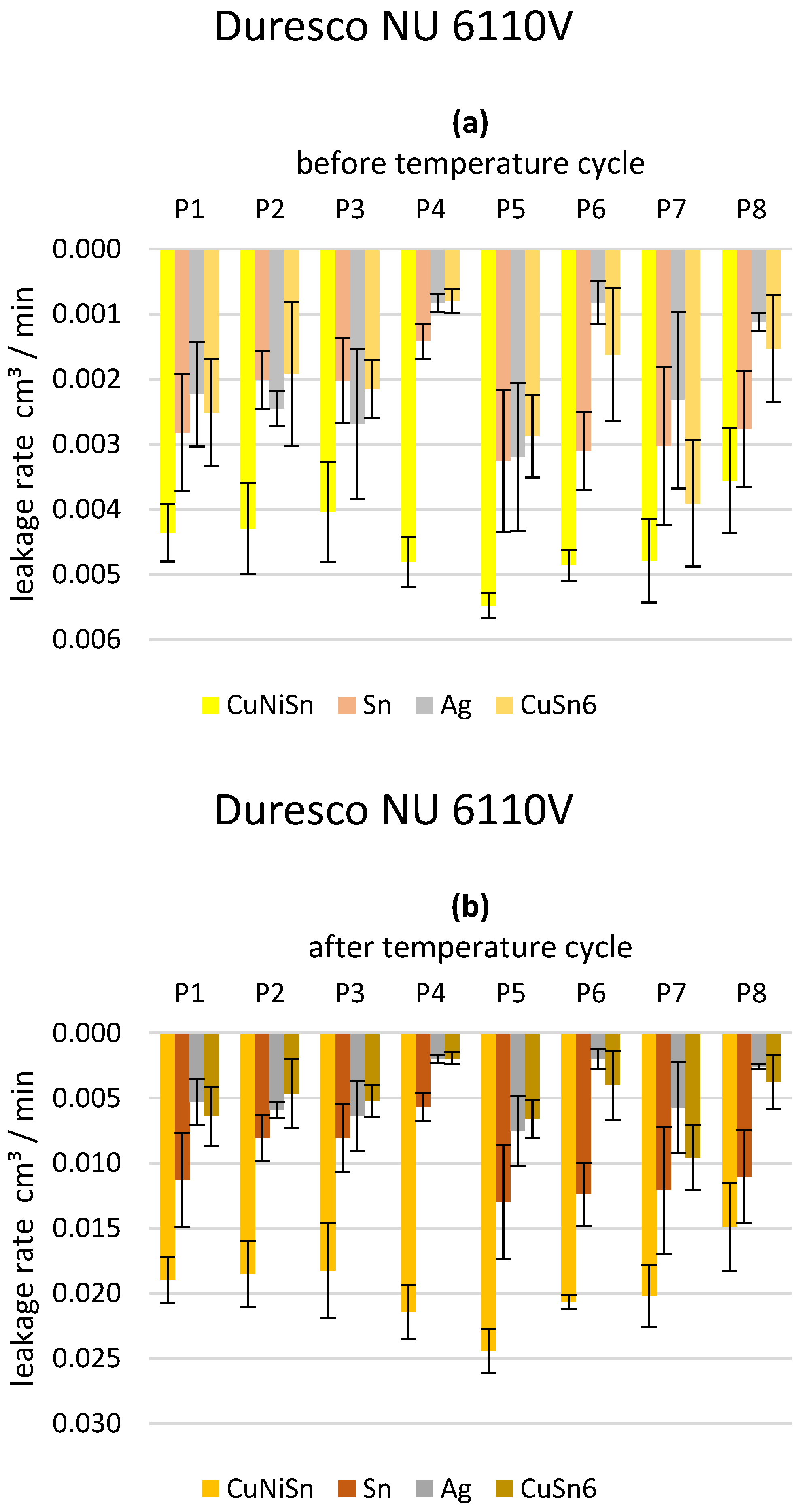
The results of the leak test before and after the temperature cycling test with the individual process parameter sets 1–8 are shown in Figure 14 and Figure 15.
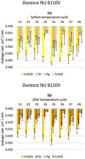
Figure 14.
Results of the leak test with Duresco NU 6110 V for the parameter sets defined in Table 2: (a) before temperature cycling; (b) after temperature cycling.
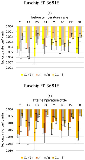
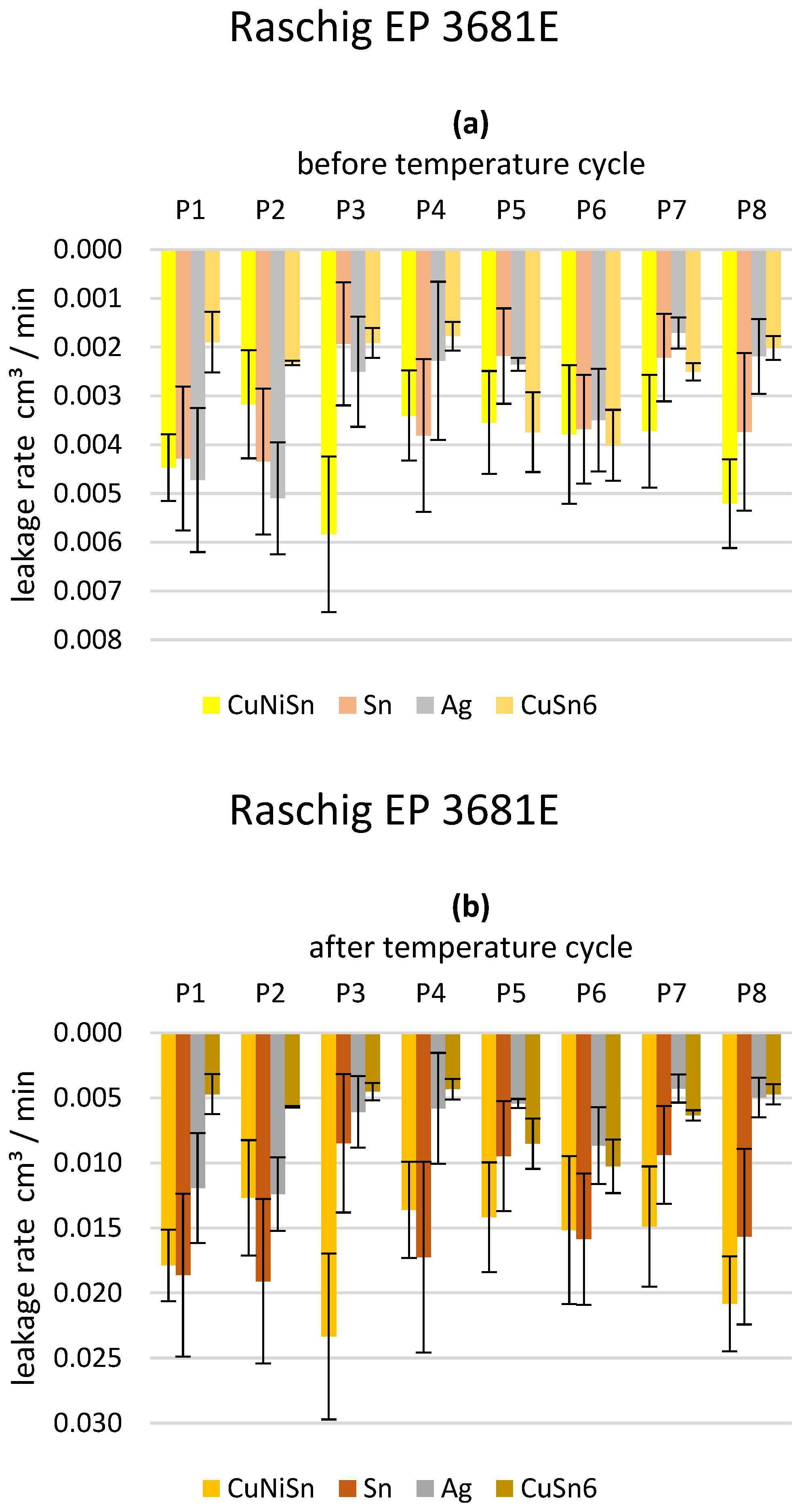
Figure 15.
Results of the leak test with Raschig EP 3681 E for the parameter sets defined in Table 2: (a) before temperature cycling; (b) after temperature cycling.
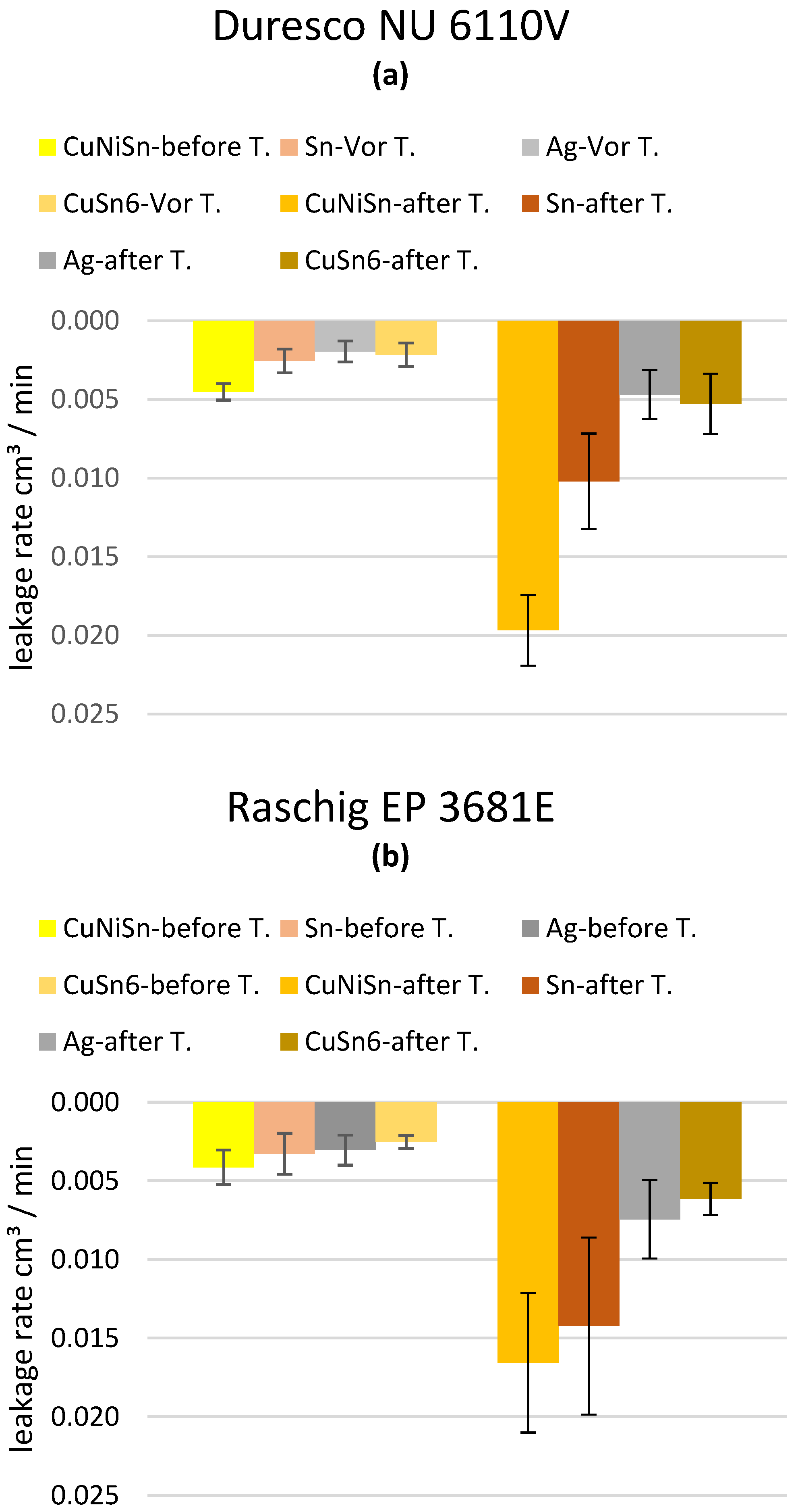
Figure 16 show the results of the leak tests before and after the temperature cycling test for different coatings and EMC. The mean values of the individual results were considered for the evaluation. The X-axis shows the respective coatings and the Y-axis illustrates the leakage rate in cm3/min.

Figure 16.
Results of the leak test, with reference to the mean values for parameter sets 1–8 of the coatings: (a) before and after temperature cycling with Duresco NU 6110 V; (b) before and after temperature cycling with Raschig EP 3681 E.
In most of the test series, the inserts which were heated prior to the encapsulation achieved a lower leakage rate. Thus, there was a linear correlation between the preheated inserts and the leakage rate.
To investigate the influence of aging on the leakage rate, temperature cycling tests were carried out. An increase in the leakage rate was observed.
The deterioration was significantly greater in the test specimens with the metallic plug contacts made of CuNiSn and Sn compared to the coatings made of Ag and CuSn6.
4. Discussion
The investigations of the reliability of the metal-polymer bond were carried out with the aid of shear tests and leakage tests. For the shear strength tests, the target value > 5 MPa was predefined. The defined target value was achieved in all test series before and after the temperature cycling test [29].
During the work, it was observed that the highest shear strength and the lowest leakage rate were achieved with the Ag and CuSn6 coatings. This may be due to the fact that these materials have a better adhesion with polymers due to their composition. Both materials are known for developing stable oxide layers at their surface, usually being able to handle several oxidation states, which further prevent oxygen penetration into the deeper material. The state of oxidation allows for better bonding to the epoxy s. zuvor, Vernetzung (crosslinking) findet im Polymer statt, thus better interfaces can be formed. Pure Sn on the other hand shows segregation effects just at the temperature level of 150 °C, where SnO starts crystallizing into platelets of SnO2 [31], which appears to have an effect on the shear strength, either by mechanical instability of the crystalline segregations, or by the single state oxidation layer just below the point of cross linking. CuNiSn has dominant effects of Ni, which has very small diffusion activity and generally also develops a single oxidation state at the given temperatures. Furthermore, CuNiSn develops complex reactions based on temperature exposure, whereas at limits, usually above 300 °C, Cu and Cu2O is displaced by reactions involving Ni [32].
Furthermore, increased shear strength was found with preheated plug contacts. Although the evaluation of the results shows a significant change, this could not be confirmed for all measurement series and requires further investigation. However, this effect strengthens the assumption that the shear strength is related to cross linking. Both the potential of surface reactions of the metal and the exothermic cross linking reaction are impacted by this parameter. In addition, it was observed that the investigated process parameter sets had no direct influence on the results. This may be due to the fact that the metal-polymer bond is mostly attributed to chemical and less to mechanical effects. Nonetheless, additional mechanical anchoring can increase the shear strength.
The shear strength results were higher after the temperature cycling test than before. This may be related to the fact that the EMC has not completed the full cross-linking process immediately after sampling. Thus, the components are post-cured in the temperature cycling test and reach full curing after a certain time. The results show that fully cross-linked EMC form a better bond with the insert plug contact. The increase in shear strength proves that that the EMCs were not yet fully cross-linked directly after molding and further tempering in any form allows to increase the shear strength.
In most cases, the leakage rate requirement is linked to the respective application and its subsequent conditions of use. Within the scope of the investigations, a target value of <0.02 cm3/min was defined. For the Ag and CuSn6 coatings, the results were all below this value, meeting the criteria. In most test series, the preheated inserts achieved a lower leakage rate. Thus, there was a linear correlation between the preheating of the inserts and the leakage rate. This is possibly due to the fact that the heating of the inserts minimizes the stresses, since both melt and insert are at elevated temperature during processing, whereas cold inserts and hot melt present a significant mismatch during cool down. Furthermore, as shown above, the preheating of the inserts improved the bonding between metal surface and EMC. With a few exceptions, this value was not achieved for the coating with CuNiSn and Sn.
To investigate the influence of aging on the leakage rate, temperature cycling tests were carried out. The effect was assumed to lead to higher leakage rates due to deterioration of the interface by thermomechanical expansion of the material. However, the shear test showed that the bonding quality improved, thus leading to the assumption that the leakage rate improves, too. However, an increase in the leakage rate was observed. The deterioration was significantly greater in the test specimens with metallic connector contacts made of CuNiSn and Sn compared to the coatings made of Ag and CuSn6. When conducting the leakage tests, it can be assumed that the test specimens were fully cross-linked, since the time between sampling and characterization was much longer than in the shear tests.
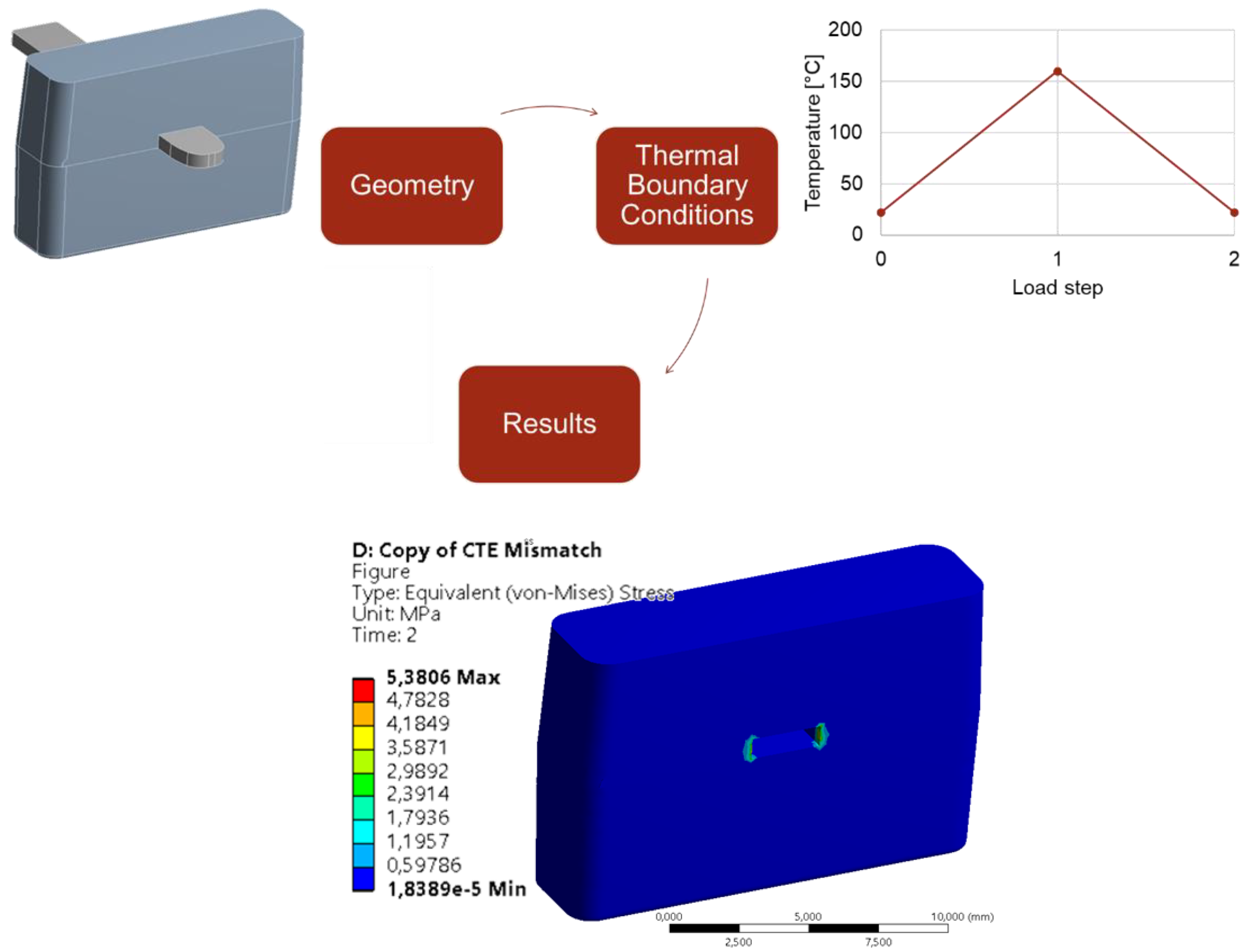
It was observed that the shear strength and the leakage rate after the temperature cycling test correlate inversely with each other. This can possibly be attributed to the different material pairings and the resulting material-specific thermal expansion coefficients. As already described, the temperature shock test leads to an increase of the shear strength and a deterioration of the leak proofing results. The different coefficients of thermal expansion may lead to increased stresses at the corner points of the interface. Due to the stresses, cracking occurs at these points, but this has no effect on the adhesion of the material pairs. To confirm the existence of the critical areas of contact around the metal pin, a thermo-mechanical simulation in sigmasoft was carried out. A single pair of metal pin and the over molded EMC was considered for the purpose of this simulation. The simulation was carried out using the element birth and death technique in ANSYS. At the beginning of the first step of the simulation at 22 °C the elements comprising the EMC are assumed to be absent. The metal pin is then heated up to 160 °C, corresponding to the placing of the pin in the molding tool and preheating it. The elements comprising the EMC “take birth” at this stage, corresponding to the injection molding stage. In the end of the last stage, the assembly is cooled down to room temperature conditions. The presence of mismatch in the coefficient of thermal expansion values of both the materials involved leads to residual stresses at the contact area (light blue marks in the results part of Figure 17).

Figure 17.
Flow diagram of the Simulation process.
In summary, although the adhesion of the material pairings and thus the shear strength is increased, the leakage rate due to micro cracks deteriorates after the temperature cycling test. This is possibly due to the fact that the material pairings (EMC and insert) have different coefficients of thermal expansion. Thus, the components expand differently when heated. This can also be seen in the simulation in, where visual examinations were carried out using sigmasoft. A weak point was found at the corner points of the plastic-metal joints. Conclusively, round pins could further improve the leak rate towards better hermeticity, however production costs and already met requirements using the stamped inserts do not require further optimization regarding the aimed applications.
5. Conclusions and Summary
Different material combinations of EMC-metal interfaces were investigated regarding mechanical strength and hermeticity. Different process variations were tested. For the shear strength tests, a target value > 5 MPa was predefined. The defined target value was achieved in all test series before and after the temperature cycling test [29]. In most cases, the leakage rate requirement is linked to the respective application and its subsequent conditions of use. Within the scope of the investigations, a target value of <0.02 cm3/min was defined. For the Ag and CuSn6 coatings, the results were all below this value, meeting the criteria. In most test series, the preheated inserts achieved a lower leakage rate.
It could be identified that specific coatings significantly improve both, mechanical strength and hermeticity. While it was assumed that the hermeticity correlates with the shear strength, the opposite was confirmed. Micro crack development in well cross-linked material combinations appear to increase the leakage rate. While the effect could be studied within this experimental setup, further investigations are necessary to fully understand the effect and further optimize the composite system.
In view of the above, the shear strength results can be used for hybrid components with metallic inserts in conjunction with EMCs. For the safe design of the metal-polymer composite, the results of the leakage test should be used. The measured shear strength should be able to give an indication of the material pairings from which the metal-polymer joints can be designed. The final validation should always be done with the help of a leakage test.
Author Contributions
Conceptualization; methodology; investigation; formal analysis, M.H.; simulation, R.K.; coating, S.W.; tool design, T.R. and M.H.; experiments, characterization, M.H.; writing—original draft preparation, M.H.; writing—review and editing, R.K., S.S., T.G. (Thomas Guenther), T.G. (Tobias Grözinger) and A.Z.; supervision, S.S. and T.G. (Thomas Guenther); project administration, M.H.; funding acquisition, T.G. (Thomas Guenther), A.Z. All authors have read and agreed to the published version of the manuscript.
Funding
This work was done in the scope of the research project AiF-DuroConnect financed by the German Federal Ministry for Economic Affairs and Energy (BMWi) through the German Federation of Industrial Research Associations eV (AiF): 20288 N. Authors would like to thank the different project partners and funding institutes.
Data Availability Statement
All data used are show in the text. Raw data are available on request.
Conflicts of Interest
The authors declare no conflict of interest.
References
- Shpak, N.; Kuzmin, O.; Dvulit, Z.; Onysenko, T.; Sroka, W. Digitalization of the Marketing Activities of Enterprises: Case Study. Information 2020, 11, 109. [Google Scholar] [CrossRef] [Green Version]
- Ardebili, H.; Zhang, J.; Pecht, M.G. Encapsulation Technologies for Electronic Applications; William Andrew: Cambridge, UK, 2018; ISBN 978-0-12-811979-2. [Google Scholar]
- Feckova Skrabulakova, E.; Ivanova, M.; Rosova, A.; Gresova, E.; Sofranko, M.; Ferencz, V. On Electromobility Development and the Calculation of the Infrastructural Country Electromobility Coefficient. Processes 2021, 9, 222. [Google Scholar] [CrossRef]
- Center Sustainability and Excellence (CSE). Electromobility: The New Trend in the Transport Sector to Meet EU Goals; Centre for Sustainabilty and Excellence: Chicago, IL, USA, 2021. [Google Scholar]
- Bioeconomy–The Global Trend and Its Implications for Sustainability and Food Security-ScienceDirect. Available online: https://www.sciencedirect.com/science/article/abs/pii/S2211912418300865 (accessed on 13 October 2021).
- Correa-Baena, J.-P.; Hippalgaonkar, K.; van Duren, J.; Jaffer, S.; Chandrasekhar, V.R.; Stevanovic, V.; Wadia, C.; Guha, S.; Buonassisi, T. Accelerating Materials Development via Automation, Machine Learning, and High-Performance Computing. Joule 2018, 2, 1410–1420. [Google Scholar] [CrossRef] [Green Version]
- Yole Developpement. MEMS and Sensors for Automotive: Market & Technology Report. 2017. Available online: https://bit.ly/2X5pL70 (accessed on 23 July 2021).
- Hartung, M. Verfahren Zur Erhöhung Der Zuverlässigkeit Und Verlängerung Der Lebensdauer Elektronischer Baugruppen Durch Dynamische Belastungsreduzierung Während Des Betriebs. Ph.D. Thesis, Universität Rostock, Rostock, Germany, 2017. [Google Scholar]
- Băjenescu, T.-M.I. Halbleiterpackaging/Verpackungstechnologien und Zuverlässigkeit. In Zuverlässige Bauelemente für elektronische Systeme: Fehlerphysik, Ausfallmechanismen, Prüffeldpraxis, Qualitätsüberwachung; Băjenescu, T.-M.I., Ed.; Springer Fachmedien: Wiesbaden, Germany, 2020; pp. 101–164. ISBN 978-3-658-22178-2. [Google Scholar]
- Sasajima, H.; Watanabe, I.; Takamoto, M.; Dakede, K.; Itoh, S.; Nishitani, Y.; Tabei, J.; Mori, T. New Development Trend of Epoxy Molding Compound for Encapsulating Semiconductor Chips. In Materials for Advanced Packaging; Lu, D., Wong, C.P., Eds.; Springer International Publishing: Cham, Switzerland, 2017; pp. 373–419. ISBN 978-3-319-45098-8. [Google Scholar]
- Kaiser, V. Die Welt der Steckverbinder–Technologien und Trends. Available online: https://www.zvei.org/presse-medien/publikationen/die-welt-der-steckverbinder-technologien-und-trends (accessed on 28 September 2021).
- Bonpain, B. Entwicklung und prozesstechnische Analyse eines festen und mediendichten Kunststoff-Metall-Verbundes. Ph.D. Thesis, Technische Universität Dortmund, Dortmund, Germany, 2016. [Google Scholar]
- Endemann, U. Werkstoffverbunde-Kunststoff Und Metall Im Festen Verbund. Kunstst. Werkst. Verarb. Anwend. Organ Dtsch. Kunstst.-Fachverbände 2002, 92, 110–114. [Google Scholar]
- Ehrenstein, G.W. Handbuch Kunststoff-Verbindungstechnik. Available online: https://www.hanser-kundencenter.de/fachbuch/artikel/9783446226685 (accessed on 28 September 2021).
- Heinle, M.; Frey, P.; Merklein, M.; Drummer, D. Zeitschrift Kunststofftechnik Journal of Plastics Technology-PDF Kostenfreier Download. Available online: https://docplayer.org/146697995-Zeitschrift-kunststofftechnik-journal-of-plastics-technology.html (accessed on 28 September 2021).
- Hera, D. Leiterplattenbasiertes Packaging zur Systemintegration mittels Film-Assisted Transfer Molding. Ph.D. Thesis, Fakultät Konstruktions-, Produktions- und Fahrzeugtechnik der Universität Stuttgart, Stuttgart, Germany, 2018. [Google Scholar]
- Gerd Helmut, T. Eigenschaften Und Anwendungen von Epoxid-Formmassen-PDF Kostenfreier Download. Available online: https://docplayer.org/33686647-Eigenschaften-und-anwendungen-von-epoxid-formmassen.html (accessed on 28 September 2021).
- Jang, J.B.; Kim, T.H.; Kim, T.; Kim, H.J.; Seo, B.; Lim, C.-S.; Lee, W. Modified Epoxy Resin Synthesis from Phosphorus-Containing Polyol and Physical Changes Studies in the Synthesized Products. Polymers 2019, 11, E2116. [Google Scholar] [CrossRef] [PubMed] [Green Version]
- Kulkarni, R.; Soltani, M.; Wappler, P.; Guenther, T.; Fritz, K.-P.; Groezinger, T.; Zimmermann, A. Reliability Study of Electronic Components on Board-Level Packages Encapsulated by Thermoset Injection Molding. J. Manuf. Mater. Process. 2020, 4, 26. [Google Scholar] [CrossRef] [Green Version]
- Schüle, H.; Bille, H.; Emmerich, R.; Hegemann, B.; Ziegler, L.; Diemert, J.; Gittel, D.; Göttke, S.; Kauffmann, A.; Knoblauch-Xander, M.; et al. Verarbeitung von Kunststoffen zu Bauteilen. In Polymer Engineering: Technologien und Praxis; Eyerer, P., Elsner, P., Hirth, T., Eds.; VDI-Buch; Springer: Berlin/Heidelberg, Germany, 2008; pp. 211–435. ISBN 978-3-540-72419-3. [Google Scholar]
- Katzier, D.H. Elektrische Steckverbinder—Technologien, Anwendungen Und Anforderungen. In Elektrische Steckverbinder; Eugen G. Leuze Verlag KG: Bad Saulgau, Germany, 2012; ISBN 978-3874802734. [Google Scholar]
- Lauter, C.; Tröster, T.; Homberg, W. Entwicklung und Herstellung von Hybridbauteilen aus Metallen und Faserverbundkunststoffen für den Leichtbau im Automobil; Elektronische Ressource: Paderborn, Germany, 2016. [Google Scholar]
- Schürmann, H. Einleitung. In Konstruieren mit Faser-Kunststoff-Verbunden; VDI-Buch; Springer: Berlin/Heidelberg, Germany, 2007; pp. 1–12. ISBN 978-3-540-72190-1. [Google Scholar]
- Vinaricky, E. Anwendungsbeispiele für elektrische Kontakte. In Elektrische Kontakte, Werkstoffe und Anwendungen: Grundlagen, Technologien, Prüfverfahren; Vinaricky, E., Ed.; Springer: Berlin/Heidelberg, Germany, 2002; pp. 389–573. ISBN 978-3-642-56237-2. [Google Scholar]
- Datasheet NU 6110V, 2021; Company Duresco, Benkenstrasse 250, 4108 Witterswil, Switzerland. Available online: https://www.duresco.ch/wp-content/uploads/NU-6110-datasheet.pdf (accessed on 29 September 2021).
- Datasheet EP 3681E, 2021; Company Raschig, Mundenheimer Straße 100, 67061 Ludwigshafen/Rhein, Germany. 2021. Available online: https://www.raschig.de/downloads/buk/tdb/TDB%20-%20Epoxidur%20EP%203681%20E.pdf (accessed on 29 September 2021).
- Klein, M. Klein Einführung in Die DIN-Normen, 13th ed.; Vieweg+Teubner Verlag: Stuttgart/Leipzig/Wiesbaden, Germany, 2001; ISBN 978-3-322-92719-4. [Google Scholar]
- Lioba, T. Verarbeitung von Rieselfähigen Duroplastischen Formmassen. Available online: https://docplayer.org/20966189-Verarbeitung-von-rieselfaehigen-duroplastischen-formmassen.html (accessed on 29 September 2021).
- Haynes, W.M.; Lide, D.R.; Bruno, T.J. CRC Handbook of Chemistry and Physics: A Ready-Reference Book of Chemical and Physical Data, 95th ed.; Apple Academic Press Inc.: Boca Raton, FL, USA; London, UK; New York, NY, USA, 2014; ISBN 978-1-4822-0867-2. [Google Scholar]
- Stoffdaten Und Kennwerte Der Verfahrenstechnik | Wolfgang Fratzscher | Hardcover. ISBN 9783342006336. Available online: https://www.isbn.de/buch/9783342006336_stoffdaten-und-kennwerte-der-verfahrenstechnik.htm (accessed on 30 September 2021).
- Tamai, T.; Nabeta, Y.; Sawada, S.; Hattori, Y. Property of Tin Oxide Film Formed on Tin-Plated Connector Contacts. In Proceedings of the 56th IEEE Holm Conference on Electrical Contacts, Charleston, SC, USA, 4–7 October 2010; pp. 1–8. [Google Scholar]
- Kumar, T.S.; Mallya, R.M. Surface Segregation and Oxidation Studies on Cu-Ni-Sn and Ag-Cu-Ge Ternary Alloys. Null 1988, 35, 63–75. [Google Scholar] [CrossRef]


Publisher’s Note: MDPI stays neutral with regard to jurisdictional claims in published maps and institutional affiliations. |
© 2021 by the authors. Licensee MDPI, Basel, Switzerland. This article is an open access article distributed under the terms and conditions of the Creative Commons Attribution (CC BY) license (https://creativecommons.org/licenses/by/4.0/).