Article

PREFACE: A Search for Long-Lived Particles at the Large Hadron Collider

1
Institute of Graduate Studies in Sciences, Istanbul University, 34116 Istanbul, Turkey
2
Department of Physics, Istanbul University, 34134 Istanbul, Turkey
3
Theoretical Physics Department, CERN, 1211 Geneva 23, Switzerland
4
Fermi National Accelerator Laboratory, Batavia, IL 60510-5011, USA
5
Department of Physics and Astronomy, College of Liberal Arts and Sciences, The University of Iowa, Iowa City, IA 52242-1479, USA
6
Department of Physics, Erzincan Binali Yıldırım University, 24002 Erzincan, Turkey
*
Author to whom correspondence should be addressed.
Physics 2025, 7(3), 33; https://doi.org/10.3390/physics7030033 (registering DOI)
Submission received: 12 March 2025 / Revised: 21 May 2025 / Accepted: 27 May 2025 / Published: 1 August 2025
(This article belongs to the Section High Energy Physics)

Abstract

The Standard Model (SM) fails to explain many problems (neutrino masses, dark matter, and matter–antimatter asymmetry, among others) that may be resolved with new particles beyond the SM. No observation of such new particles may be explained either by their exceptionally high mass or by considerably small coupling to SM particles. The latter case implies relatively long lifetimes. Such long-lived particles (LLPs) then to have signatures different from those of SM particles. Searches in the “central region” are covered by the LHC general purpose experiments. The forward small angle region far from the interaction point (IP) is unexplored. Such particles are expected to have the energy as large as E = O (1 TeV) and Lorentz time dilation factor γ = E / m 10 2 10 3 (with m the particle mass) hence long enough decay distances. A new class of specialized LHC detectors dedicated to LLP searches has been proposed for the forward regions. Among these experiments, FASER is already operational, and FACET is under consideration at a location 100 m from the LHC IP5 (the CMS detector intersection). However, some features of FACET require a specially enlarged beam pipe, which cannot be implemented for LHC Run 4. In this study, we explore a simplified version of the proposed detector PREFACE compatible with the standard LHC beam pipe in the HL-LHC Run 4. Realistic Geant4 simulations are performed and the background is evaluated. An initial analysis of the physics potential with the PREFACE geometry indicates that several significant channels could be accessible with sensitivities comparable to FACET and other LLP searches.

1. Introduction

Despite its success, the Standard Model (SM) of elementary particles cannot address several crucial questions—such as neutrino masses, dark matter, and matter–antimatter asymmetry—that may require a new theory and new particles beyond the SM (BSM). Experiments at the LHC at CERN are making significant efforts to search for BSM phenomena and identify their possible constituents [1,2,3]. In the near future, the LHC is planned to operate at even higher luminosities [4,5], enabling a deeper exploration of these questions [6]. This is of a particular importance for discovering new particles that may have exceptionally small cross sections or quite weak couplings to SM particles [7,8].

1.1. BSM Benchmark Models of a Dark Sector

A relatively simple, coherent, and predictive framework [9,10] for BSM states is often linked to a so-called “dark sector”, which interacts with the SM “visible” sector via “portals” [11,12,13]. Due to the constraints imposed by SM gauge symmetry and fields, only a few viable portal options exist: vector, scalar, fermion, and axion-like particle (ALP) portals. These straightforward and well-motivated benchmark models predict a wide range of phenomena, driving the development of a number of new searches and specialized experiments that complement other (for example, cosmic) probes.
Depending on the model, a long-lived particle (LLP) may have one or two couplings governing both the production channels of the mediator or rare SM particle and its visible decay modes into SM final states [14,15].

1.2. Proposed Long-Lived Particle Search Experiments

Past experiments have only excluded relatively large couplings of the portal particles to new physics [12,13]. Since the lifetime of those particles is inversely proportional to the squared coupling, they have relatively long lifetimes and are classified as LLPs.
There are several reasons why LLPs, if they are produced at the LHC, might have escaped detection, including the smallness of the event rate (proportional to the squared coupling times the LLP decay probability, which is typically negligibly small), absence of efficient selective triggers, and overwhelming SM backgrounds. To address these issues, dedicated experiments, pioneered by FASER [16], have been proposed to search for LLPs in the regions forward of the LHC IPs [17]. While the solid angle Δ Ω covered by these experiments is generally quite small, these experiments have a large enough acceptance in pseudorapidity η and azimuthal angle ϕ . The solid angle distributions of the LLP fluxes are maximal at relatively large η , which partially compensates for the smallness of the solid angle coverage.

2. Long-Lived Particle Search at Long Straight Section 5 (LSS5)

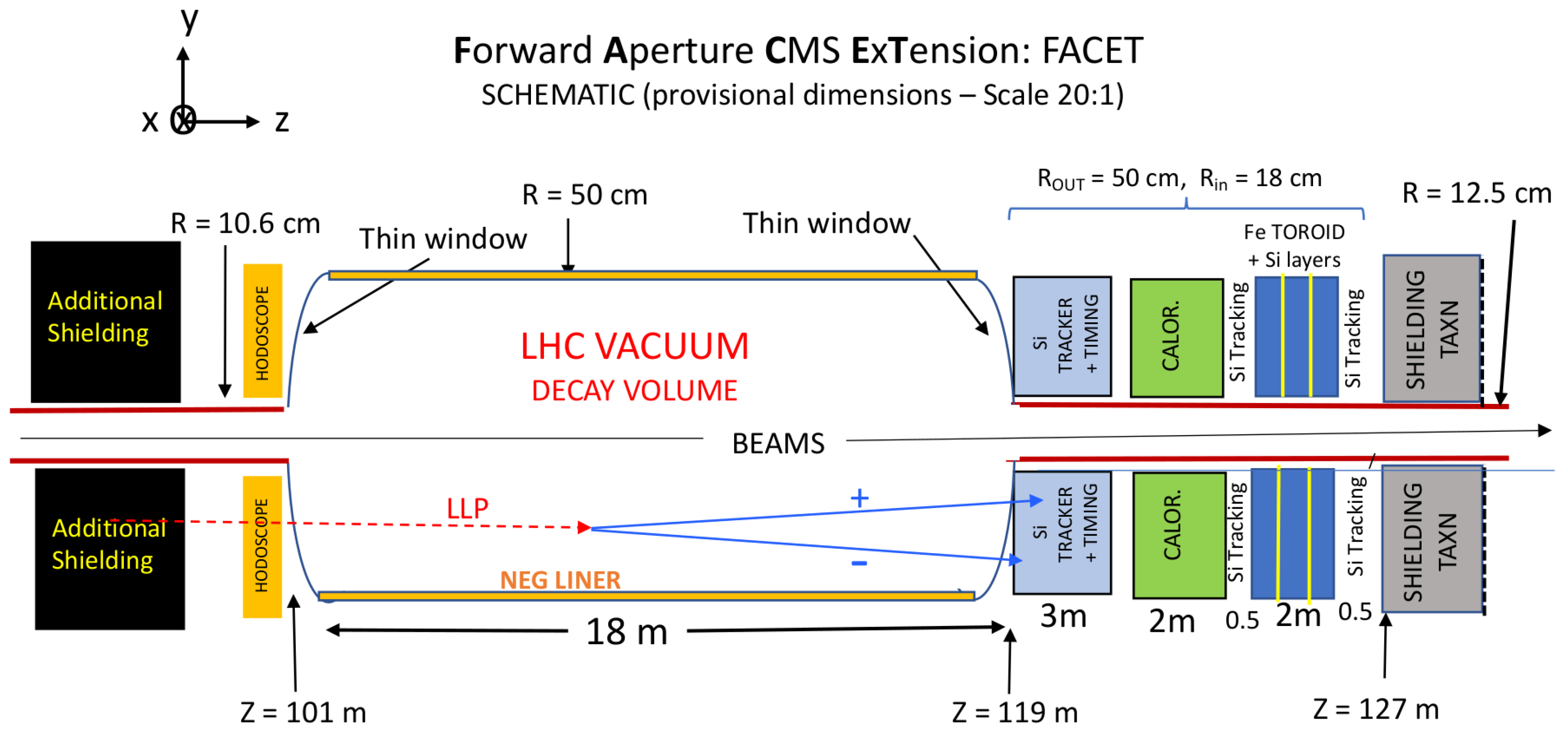
The FACET (Forward-Aperture CMS ExTension) detector, proposed [18] for installation at the LHC IP5 intersection (CMS detector), stands out for its relative proximity to IP5 (the beam axis distance z 100 m from the IP) and a fiducial volume four times longer than that of FASER, resulting in a larger acceptance. Another notable feature is its enlarged beam pipe, with a radius of r = 0.5 m between z = 100 m and z = 120 m ensuring LHC-quality vacuum conditions within the decay volume. The FACET proposal and its associated physics case has generated significant interest in the search for LLP production in the forward direction. Comparative studies with FASER and other proposed LLP detectors indicate that it performs favorably across numerous benchmarks [12]. Although initially aimed at the first HL-LHC Run 4, the special enlarged beam pipe is not possible for that run. To be compatible with the HL-LHC Run 4 beam pipe, a simplified version of FACET was considered [19]; it is described here as PREFACE (Pioneer Rare-Event Forward Apparatus for Collider Experiments) and its physics case is discussed.
Preliminary studies of the physics potential of the PREFACE geometry suggest that several key channels are accessible with sensitivity comparable to, or exceeding, that of FACET and FASER. FASER is installed in a shielded side tunnel of LHC, far enough from the nearest interaction region (ATLAS detector), while FACET and PREFACE are located in the LHC tunnel at only about 100 m from the CMS detector interaction point IP5 and are designed to sustain a high radiation environment. A “near location” downstream the target neutral beam absorber (TAXN) has been considered [20] for FASER, but has quite large backgrounds. A location upstream the TAXN, described here for FACET or PREFACE, is preferable for a more robust detector assembly; in ref. [20], a similar option is outlined in Appendix A.
The new PREFACE geometry, installed only above the standard LHC beam pipe, avoids the exceptionally high fluxes of charged particles swept to left and right by the beam separation dipole D1. Backgrounds from particles showering in the beam pipe are significantly reduced by a shielding plate between the pipe and the detectors. Reconstructing tracks in real time, with AI techniques, allows rejection at the trigger level of residual background from interactions on the beam pipes and inside the PREFACE setup, including on the air in the decay volume. Most interactions of relatively fast neutrons and K 0 in air can be rejected by topology.
PREFACE represents a realistic detector concept compatible with the standard configuration of the LHC beam pipe in the CMS detector IP5 insertion region, using shielding and detector location strategies to reduce backgrounds (with substantial saving in costs and in time with respect to the original FACET design).

2.1. Experimental Conditions at LSS5

Figure 1 gives a schematic representation of the LHC beams colliding at the experiments, with the region around IP5 expanded to show the beam trajectories and lattice elements. The two beams are bent into the same straight section where they collide, using insertion stages made of dipole magnets, D1 and D2, which bend the incoming beams into the collision point, and bend the outgoing beams back into separate pipes at the TAXN absorber.
The intersecting of the beams is further complicated by a relatively small inclination (typically 150 μrad) of the beams, either in the vertical or horizontal planes [21]. In each bunch crossing over 100 pp, collisions may occur, each producing a large enough number of particles in the full solid angle (4 π steradians). Detectors surrounding the IP measure most of the reaction products, but many escape detection through the vacuum pipes which cannot be equipped with detectors. Two exceptions are Zero Degree Calorimeters (ZDCs) [22] between the beam pipes for neutral particles and detectors in “Roman Pots” for diffractively scattered protons without disturbing the beams [23]. However, quite a number of particles hit the beam pipe and interact, creating showers of secondary particles which can be a background for detectors located nearby.

2.1.1. FACET Overview

The location foreseen for FACET in LSS5 (Figure 2) is in the field-free region between the 35 T·m superconducting beam separation dipole D1 at z = 80 m and the TAXN absorber at z = 128 m. In Figure 3, the setup is shown schematically. The decay volume is an enlarged beam pipe with radius r = 0.5 m between z = 101 m and z = 119 m; the detectors following the decay volume have full azimuthal coverage with annular shape of inner radius R in = 18 cm and outer radius R out = 50 cm, covering polar angles 1.5 < θ < 4 mrad. The background is highly reduced because of 200 300 λ i n t (interaction length) of magnetized iron in the LHC quadrupole magnets Q1–Q3 and dipole D1, and LHC quality vacuum ( 10 7 Pa– 10 9 Pa) in the decay volume.
In order to estimate the backgrounds, detailed Geant4 [24] simulations were performed with particles produced from a Fluka [25] simulation of CMS interactions at the pp collision center-of-mass energy s = 14 TeV, giving particle distributions at z 100 m. Geant4 simulation then tracks the particles produced in Fluka through the detectors.

2.1.2. Backgrounds in FACET

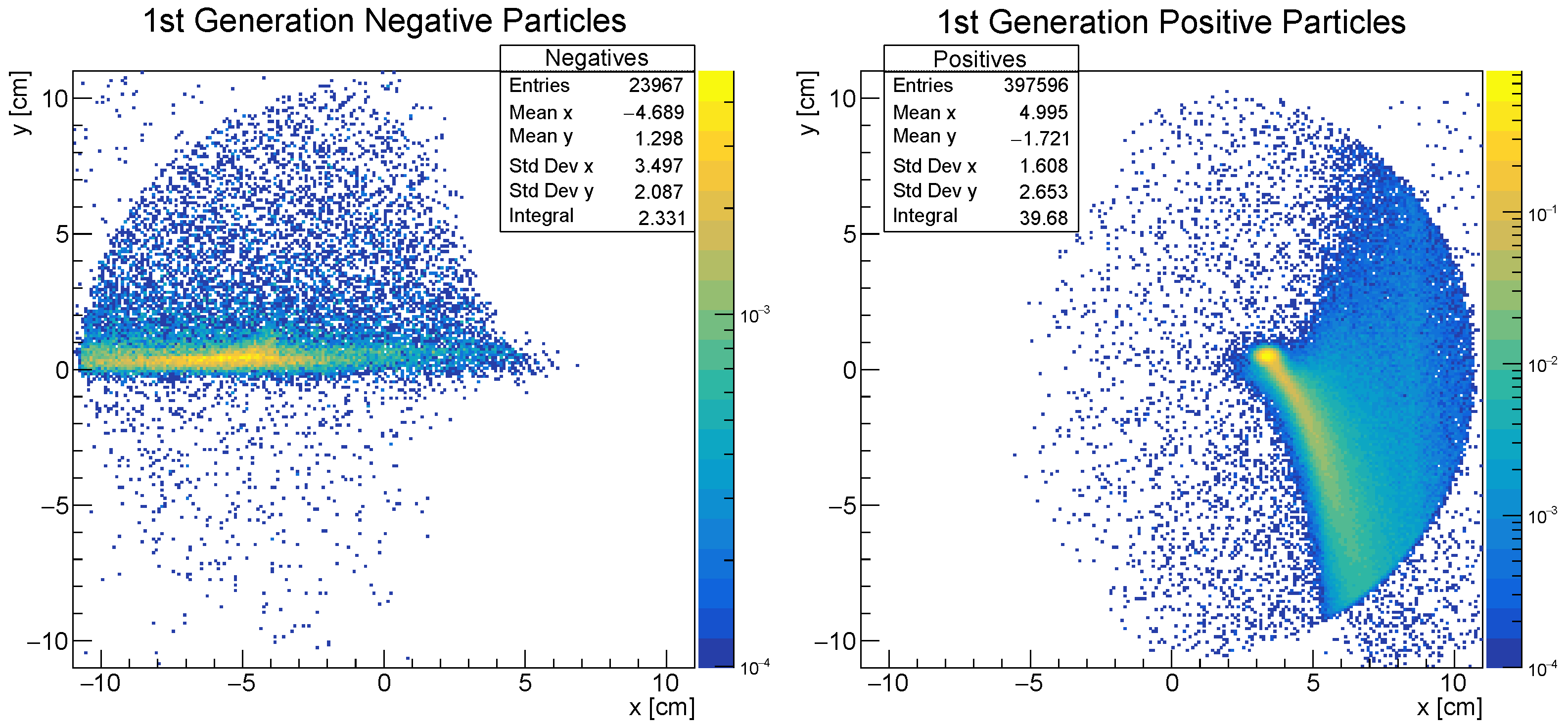
The D1 magnet bends charged particles in the horizontal plane, positives to the right and negatives to the left, as can be seen in Figure 4, where those hitting the beam pipe produce the most background. The spot at x = 3 cm, y = 0 cm shows diffractively scattered protons with energy of about 7 TeV, those with lower energy form the tail, downward because of the vertical crossing angle of the beams (for about half of the run, the crossing angle to change, so the high intensity tail to be upward). The negative particles from IP5, mostly π s, are concentrated in the horizontal plane to the left of the central beamline, and most have momenta of a few TeV.
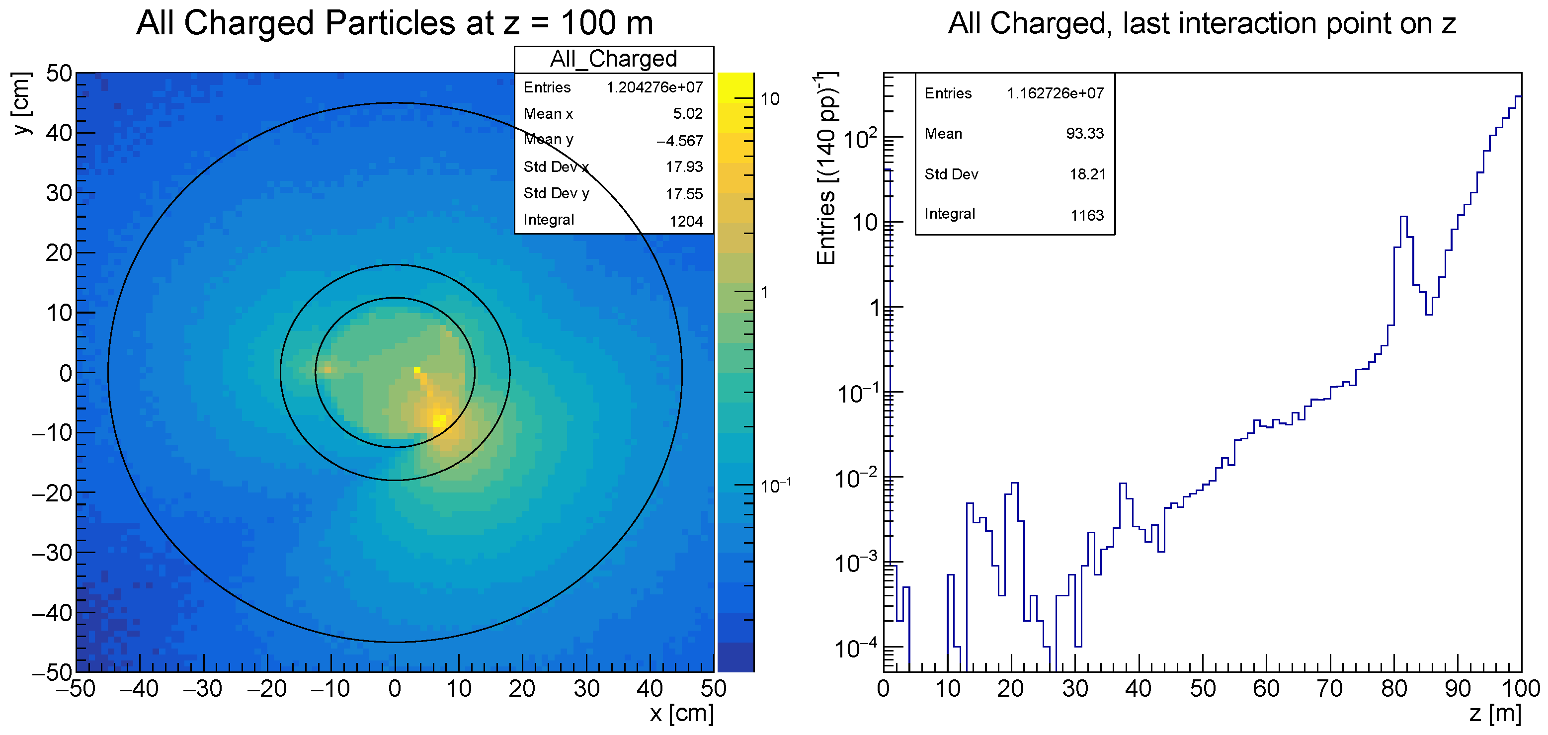
In Figure 5, the primary particles from IP5 shown in Figure 4 are concentrated inside the pipe (radius 10.6 cm). Secondary particles are mainly originating from scattering on the upstream beam pipe in the region between D1 and the “scoring plane” at 100 m. These secondary particles (mostly π + s, π s, and electrons) constitute the bright (yellow) spot near the beam pipe. Detectors near this location are to be saturated with a considerably high particle flux.
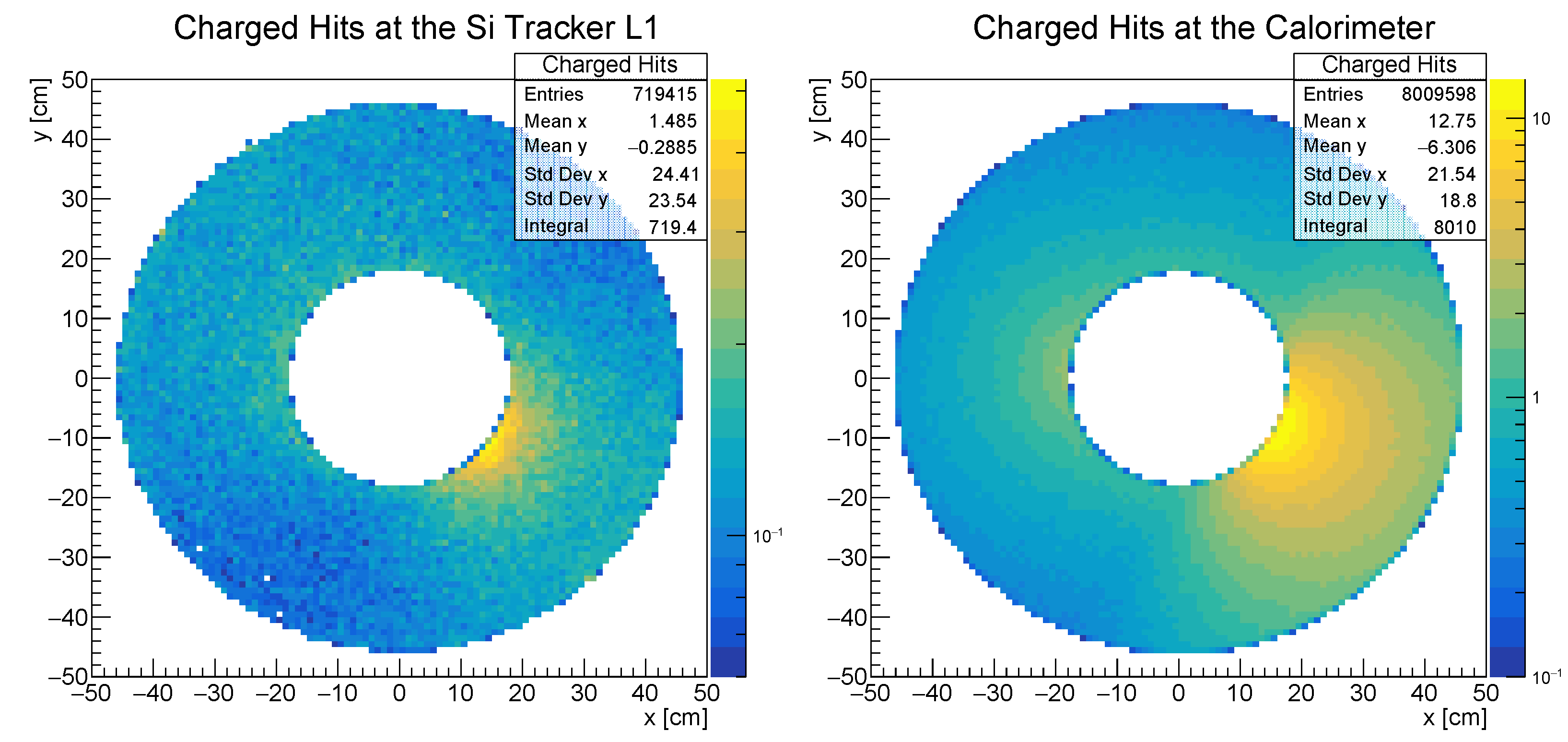
Figure 6 presents the x y -spatial distribution of charged particles (e, μ , π , p, K) at the first silicon tracker (L1) and the calorimeter. Along the trackers, the flux increases from the first tracker to the calorimeter because scatterings between the incoming particles and the beam pipe at the center of the trackers produce quite a number of secondary particles with larger polar angles than the primary ones. Although the calorimeters also have the beam pipe at their center, they exhibit significant absorption, resulting in reduced flux at the sixth tracker (L6), which is located behind the calorimeters.
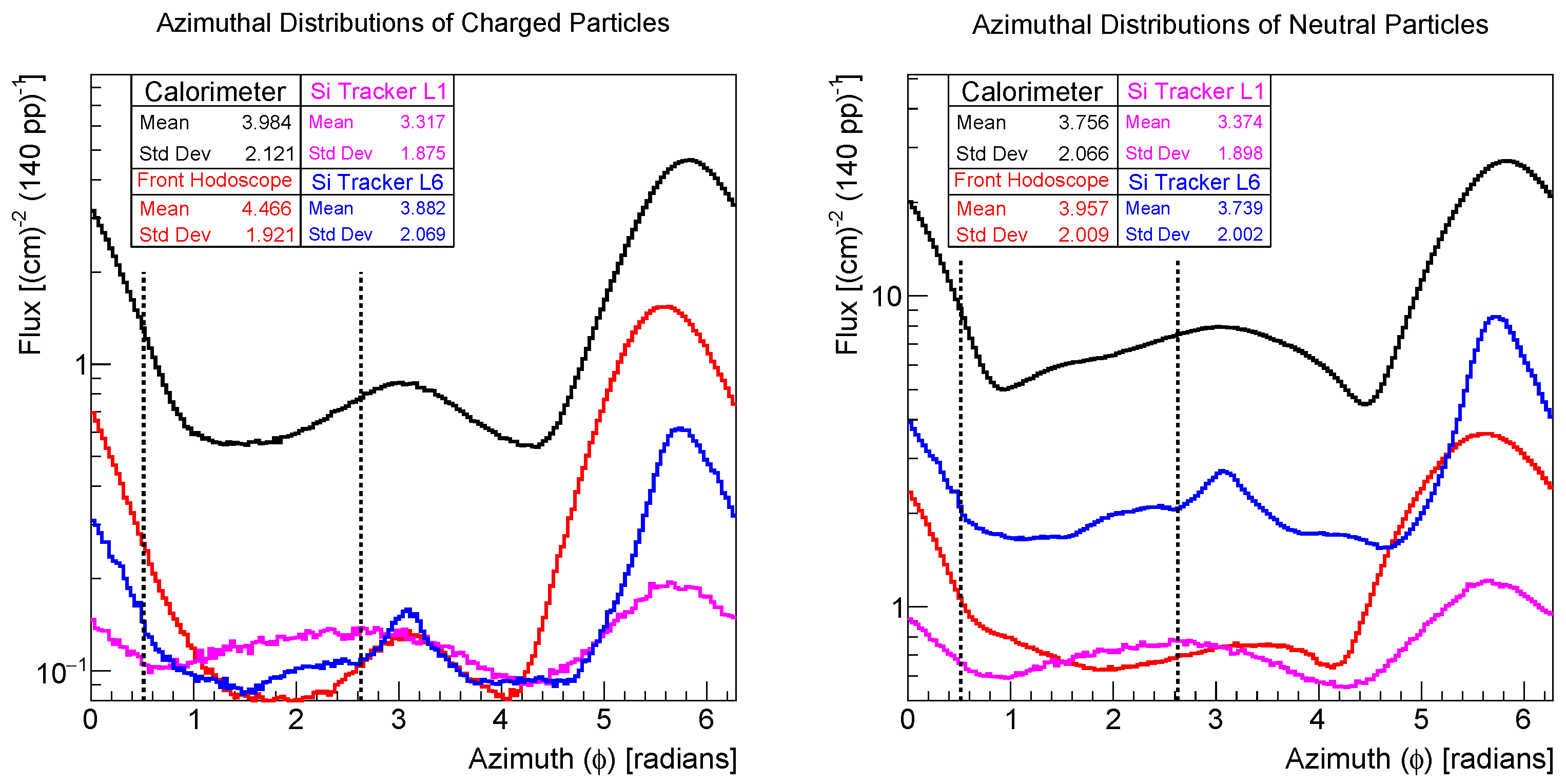
In Figure 7, the total particle flux on different detectors is distributed over azimuthal angle for Figure 7 (left) charged particles and Figure 7 (right) neutral particles ( γ , n, K L 0 ). The angle increases in the counterclockwise direction, and shows azimuthal angle distributions of flux. There are peaks around 6 rad, corresponding to 4 o’clock on the x y -plane (positives) and a second highest flux between 2 rad and 4 rad (negatives), corresponding to 9 o’clock on the x y -plane. Dashed lines indicate the azimuthal angle interval at 12 o’clock, where there is an order of magnitude-less flux and where PREFACE considered to be installed. The full acceptance version of FACET is affected by quite large particle fluxes, limiting the LLP signal/background; in the restricted azimuthal angle interval (12 o’clock), the conditions are favorable for PREFACE.

2.1.3. Limitations Imposed for Run 4

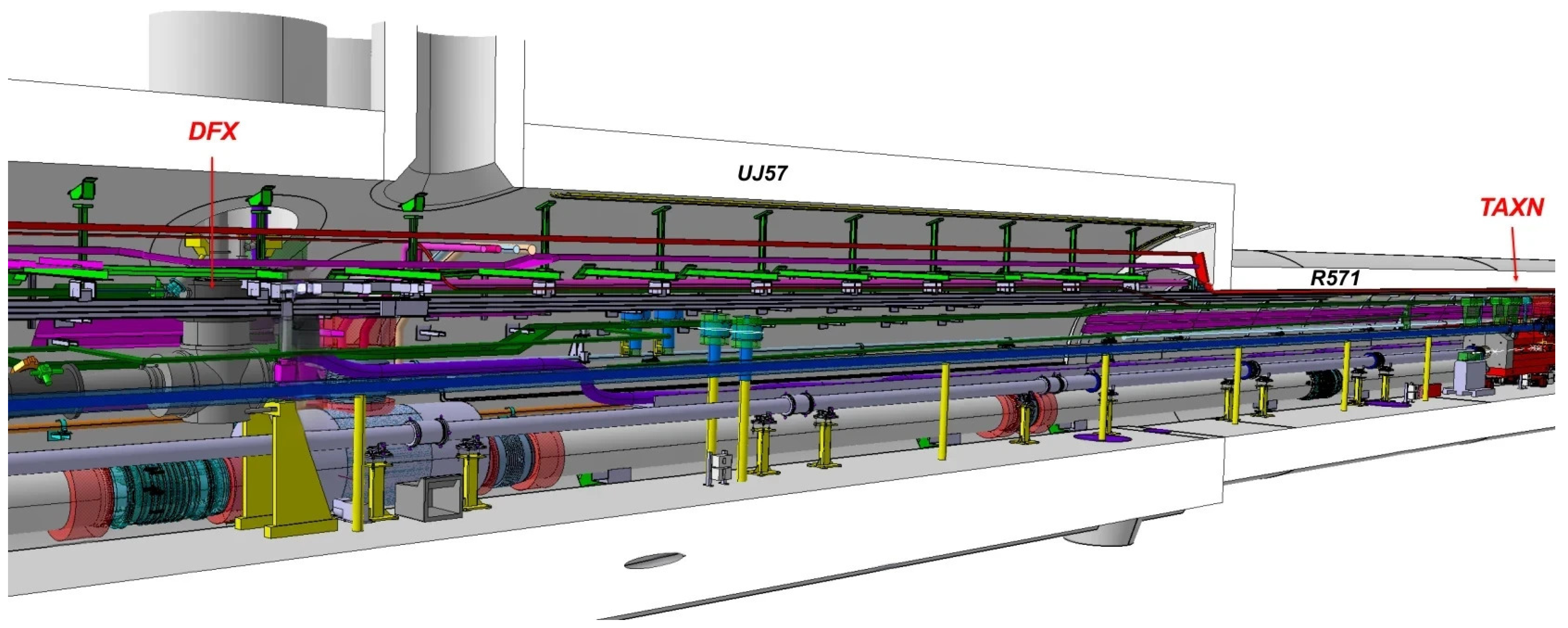
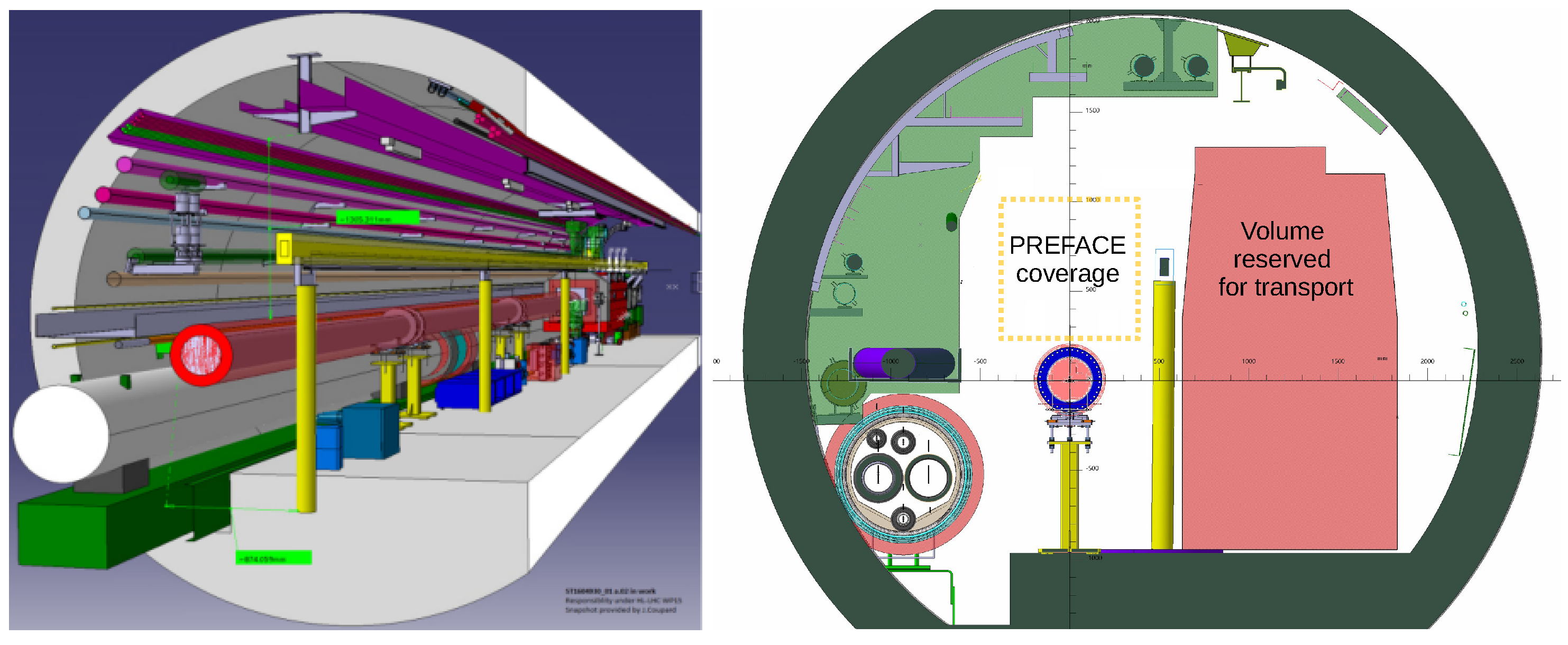
For Run 4, the setup has to be compatible with the presence of the “standard” beam pipe in the D1–TAXN drift region, as shown in Figure 8, and detectors should cover a region above the beam pipe. In Figure 9, a cut through the LHC tunnel at z = 120 m shows the limitations on the sides and below the beam pipe and a possible “free access” region above the pipe; the volume in the region marked in yellow is close to 1 m 2 , and to be equivalent to the cylindrical enlarged beam pipe initially foreseen for FACET. The transverse position of the region available for PREFACE setup corresponds to the intervals 40 cm x 40 cm and 22.5 cm y 130 cm . The effective size for PREFACE, taking into account the support plate thickness of 5 cm, and space for cable volume on top of the apparatus, is estimated as ( 80 × 80 cm 2 ), corresponding to an x y -plane interval of ( 40 cm x 40 cm ), 25 cm y 105 cm.

2.2. Figure of Merit for LLP Search Apparatus

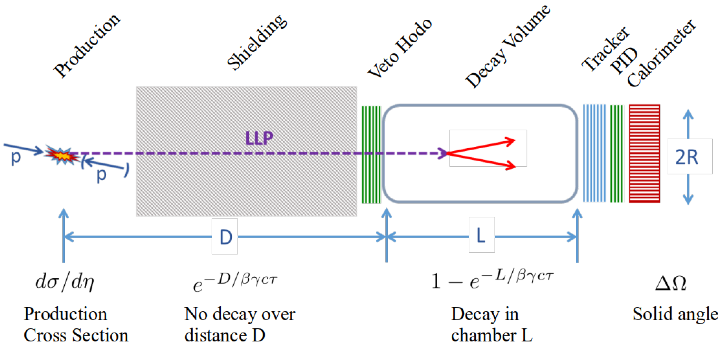
In general, an LLP search apparatus can be associated with a Figure of Merit (FoM) representing its efficiency over a range of lifetimes (Figure 10).
Postponing consideration of the production angular dependence to be discussed in Section 4, the geometric FoM of the apparatus can be described as follows:
FoM = Δ Ω exp D β γ c τ 1 exp L β γ c τ .
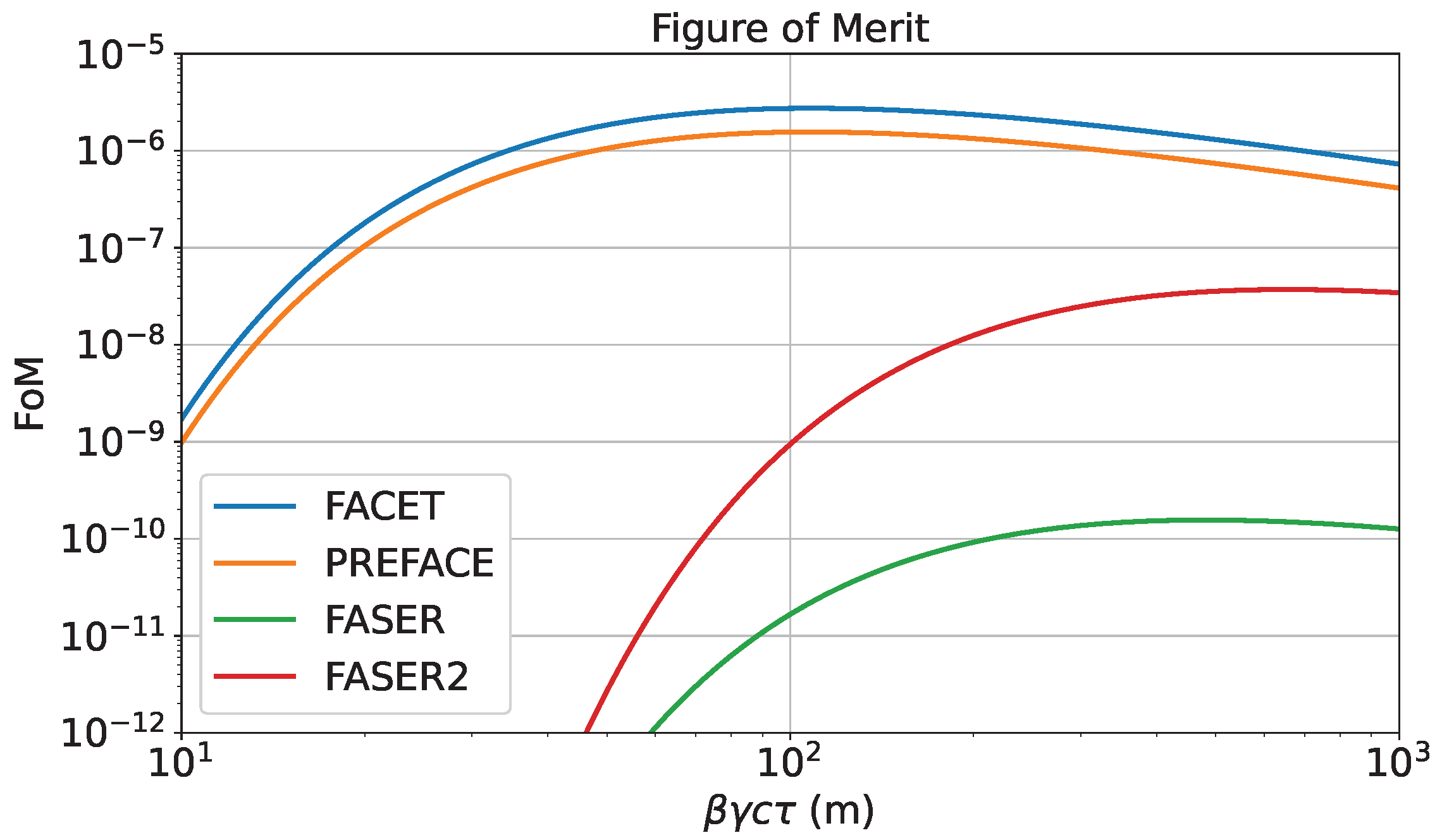
The geometrical FoM peaks at β γ c τ D , but extends over a broad interval. Here, D denotes the distance from the IP to the entrance of the decay volume, c is the speed of light, v is the speed and β is the velocity parameter β = v / c , γ is the Lorentz factor, and τ denotes the lifetime. In Figure 11, the FoM for different LLP projects (Table 1) at the LHC are shown. FACET and PREFACE are similar (having similar solid angles and decay volumes) and are orders of magnitude larger than FASER, which is at a larger distance from the production point, and also compared to FASER2 [27], a project to increase the FASER solid angle. For certain channels, the angular dependence of the production cross section may favor larger- η setups, as discussed in Section 4.

3. PREFACE Setup

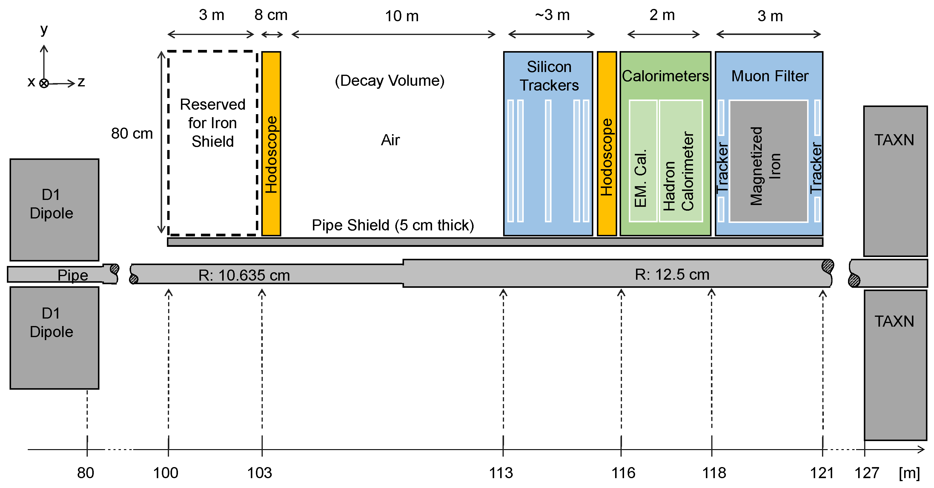
We have investigated a version (Figure 12) of the proposed PREFACE detector which is compatible with the standard LHC beam pipe in LSS5, covering only a region above the pipe. PREFACE has the same solid angle as FACET and extends to a larger polar angle θ , while avoiding the highest fluxes shown in Figure 4. It is protected from backgrounds from particles interacting in the beam pipe by a shielding plate between the pipe and the detectors. A track-based trigger is considered to select events with two or more tracks on a common vertex in a fiducial decay volume. LLPs produced at the IP5, having quite small interaction cross sections, is expected to penetrate 35–50 m of magnetized iron in the LHC quadrupole and dipole magnets and can decay to SM particles in the PREFACE detector.

3.1. PREFACE Geometry

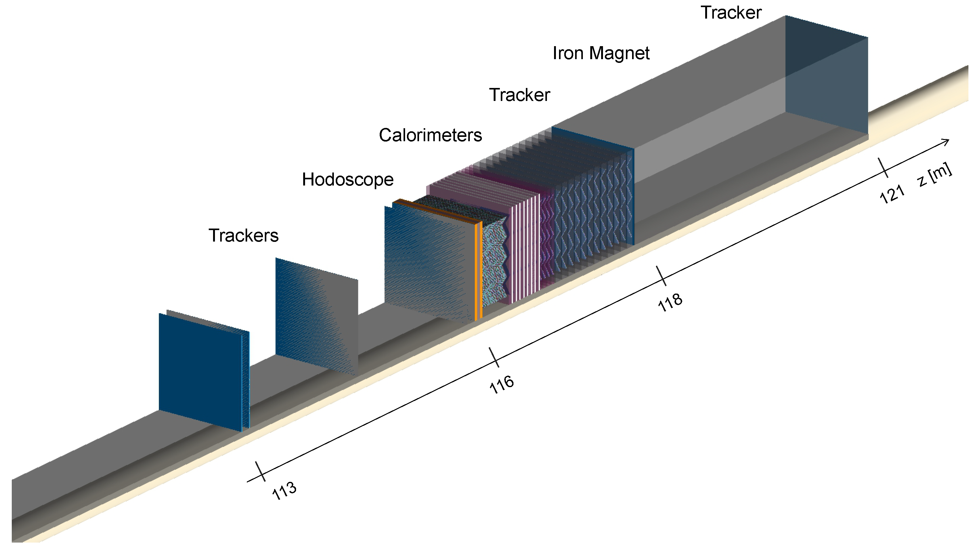
Geant4 PREFACE simulations have been performed. Input particles reaching a scoring plane at z = 100 m are obtained from a Fluka simulation compatible with the Run 4 LSS5 configuration. Geant4 PREFACE simulations start with a 3 m shield block, followed by the front hodoscope/TOF system and tracker, decay space, and downstream detector array. Additionally, a muon identifier is defined after the calorimeters; the identifier contains an (possibly permanently magnetized) iron shield between trackers. There is also a pipe shield beneath the detectors. In Figure 13, Geant4 geometry of the PREFACE detector is shown. Detectors are located above the pipe and pipe shield.

3.2. Background Estimates

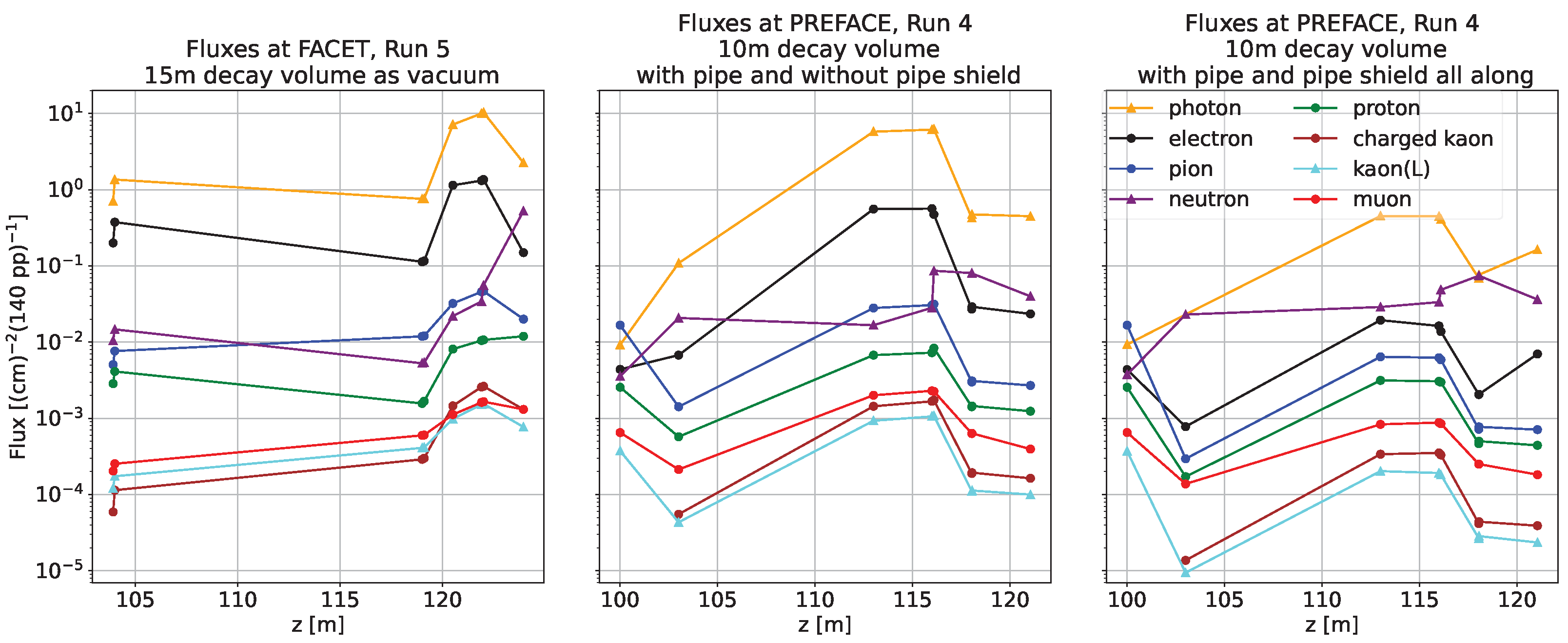
Geant4 simulations give information on backgrounds obtained from Fluka estimates, which are compared with results for FACET [18]; more quantitative background and signal estimates become possible once the PREFACE detectors’ design is finalized. In Figure 14, flux distributions over z positions are shown for three different setups. FACET (Figure 14 (left)) is compared with PREFACE variations: without pipe shield (Figure 14 (middle)) and with pipe shield (Figure 14 (right)). Hits of charged particles (e, μ , π , p, K) and neutral particles ( γ , n, K L 0 ), including anti-particles, are counted on detector components; front hodoscope, trackers, calorimeters, and behind. From Figure 14, left to middle, fluxes of photons, electrons, and muons are reduced by 82%, 83%, and 54%, respectively, behind the calorimeters, PREFACE being only above the beam pipe. Adding the pipe shield, further reductions are 84%, 92%, and 60%, respectively. The design of the pipe shield, nominally 5 cm of iron, has not been optimized. Globally, comparing FACET (Figure 14 (left)) to PREFACE with pipe shield (Figure 14 (left)), reductions are 97%, 99%, and 82% for electrons, charged hadrons, and muons, respectively.
These simulations have shown that background particle fluxes are considerably reduced from the FACET proposal, thanks to the azimuthal angle restriction excluding “hot spots” in the horizontal plane (left/right quadrants), the pipe shield, and the increased distance from the beam axis. We observe almost the same fluxes with vacuum or air in the decay volume, except for quite small variations for neutrons. Neutral hadron interactions in air, however, expected to have a different signature from LLP decays (for instance, c c ¯ , b b ¯ , and τ τ + ) and could be rejected at trigger level. Neutrino fluxes can be obtained from Fluka simulations, and their effects may be estimated in the future. The neutrinos interacting in the calorimeter are expected to have a similar signature to LLPs, but the rates to be several orders of magnitude lower than those of neutrons and neutral kaons.

3.3. Radiation Levels in the Region Foreseen for PREFACE

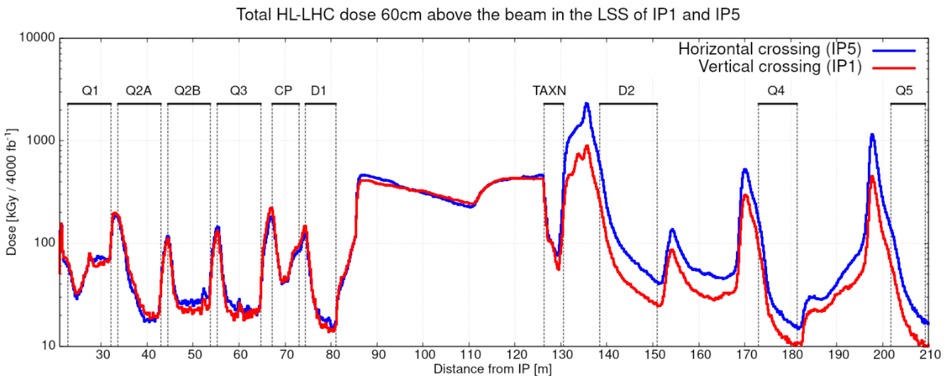
Fluka estimates of the radiation levels [28] in the LSS5 region between D1 and TAXN give Total Ionizing Dose (TID) values at different distances from the IP5, up to 60 cm above the beamline (Figure 15), using HL-LHC simulations with Optics v1.3 and vertical/horizontal crossing plane in IP1/IP5, respectively.

4. Physics Case for PREFACE

The PREFACE setup has been benchmarked with a few LLP models to assess its physics reach. The models considered are benchmark scenarios recommended by the Physics Beyond Colliders (PBC) initiative [12]: heavy neutral leptons (HNL) (the models BC6-BC8), Higgs-like scalars (the models BC4, BC5), dark photons (BC1), and axion-like particles (BC9-BC11). The description of the models is given in Table 2. These models typically have new particles in the GeV range. However, PREFACE is sensitive to many other models, such as BL (heavy baryons to heavy leptons) mediators, inelastic dark matter [29], and many others, not necessarily limited to the GeV mass range. The sensitivity of PREFACE to these scenarios is considered to be studied elsewhere.

4.1. Comparison to FACET and Other LLP Projects

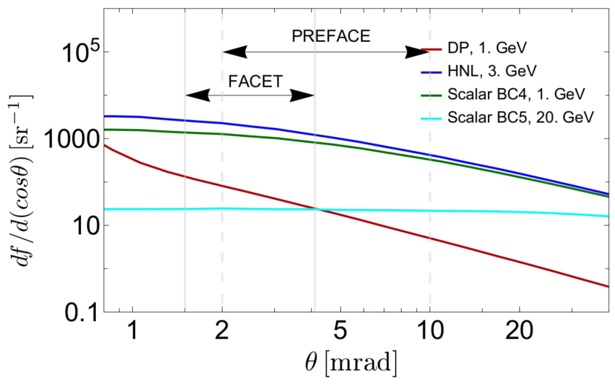
Let us now compare the physics reach of FACET and PREFACE in terms of the LLP event rates. The main difference is the angular coverage of the detectors. The solid angles are mainly the same, Ω 4.5 × 10 5 sr . FACET covers the full azimuthal angle, ϕ , with a more limited polar angle, θ . The impact of this feature can be seen by the solid angle distribution of LLPs, d f / d Ω d f / d ( cos θ ) .
Depending on the production mechanism, the distribution d f / d θ is peaking at rather small angles, θ peak . However, independent of the model, the flux d f / d ( cos θ ) is almost constant for θ < θ peak and drops at higher angles.
Figure 16 shows the angular distribution d f / d ( cos θ ) for a few LLP production processes. For Higgs-like scalars S with an h S S coupling, where h denotes the 125 GeV Higgs boson, the distribution is widely isotropic in the angular range of both FACET and PREFACE (explained by the large enough transverse momentum, p T , acquired by scalars in the main production mechanism h S S ). This changes for Higgs-like scalars without the h S S coupling, HNLs, and ALPs coupled to fermions. For these, the main production channels are decays of B mesons, and the typical p T values are smaller. In these cases, the coverage of FACET and PREFACE is slightly above θ peak . The dark photon case (the production is mainly via proton bremsstrahlung) is characterized by a smaller θ peak , and the acceptance of PREFACE is smaller than the acceptance of FACET. However, the minimal angle covered by PREFACE may be smaller than assumed here if optimized shielding allows.
The large enough distance of FACET and PREFACE from the interaction point IP5 represents a limitation for LLPs with larger couplings and therefore a smaller lifetimes compared to searches in the main central detectors (the situation in this respect is even worse for FASER and FASER2). These have LLP decay lengths c τ γ smaller than the distance from the collision point to the decay volume, where γ is the average γ -factor of the LLP. For the typical energies of LLPs, the decay probability is exponentially suppressed, and only the most energetic LLPs survive to reach the FACET and PREFACE decay volumes. The most energetic LLPs have quite small θ values and are considered to miss the PREFACE acceptance. This effect is only relevant for the case of dark photons and other vector mediators in the GeV mass range, as we show in Section 4.2 just below.

4.2. Sensitivity Calculations

To calculate the sensitivity of the PREFACE setup, we use the SensCalc package [30]. It evaluates the event rate using a semi-analytic approach. It first computes tabulated quantities: (i) the LLP production flux, (ii) the acceptance for it to decay inside the decay volume, and (iii) the acceptance for the decay products. It then calculates the number of events as the integral of the product of these quantities multiplied by the LLP’s decay probability. SensCalc package has been tested with several event generators—from light-weight Monte-Carlo simulators to the full experimental framework of SHiP and LHCb. Recently, SensCalc package has been updated with the EventCalc module, which produces detailed event information using the input from SensCalc, such as tabulated LLP production distributions and decay channels.
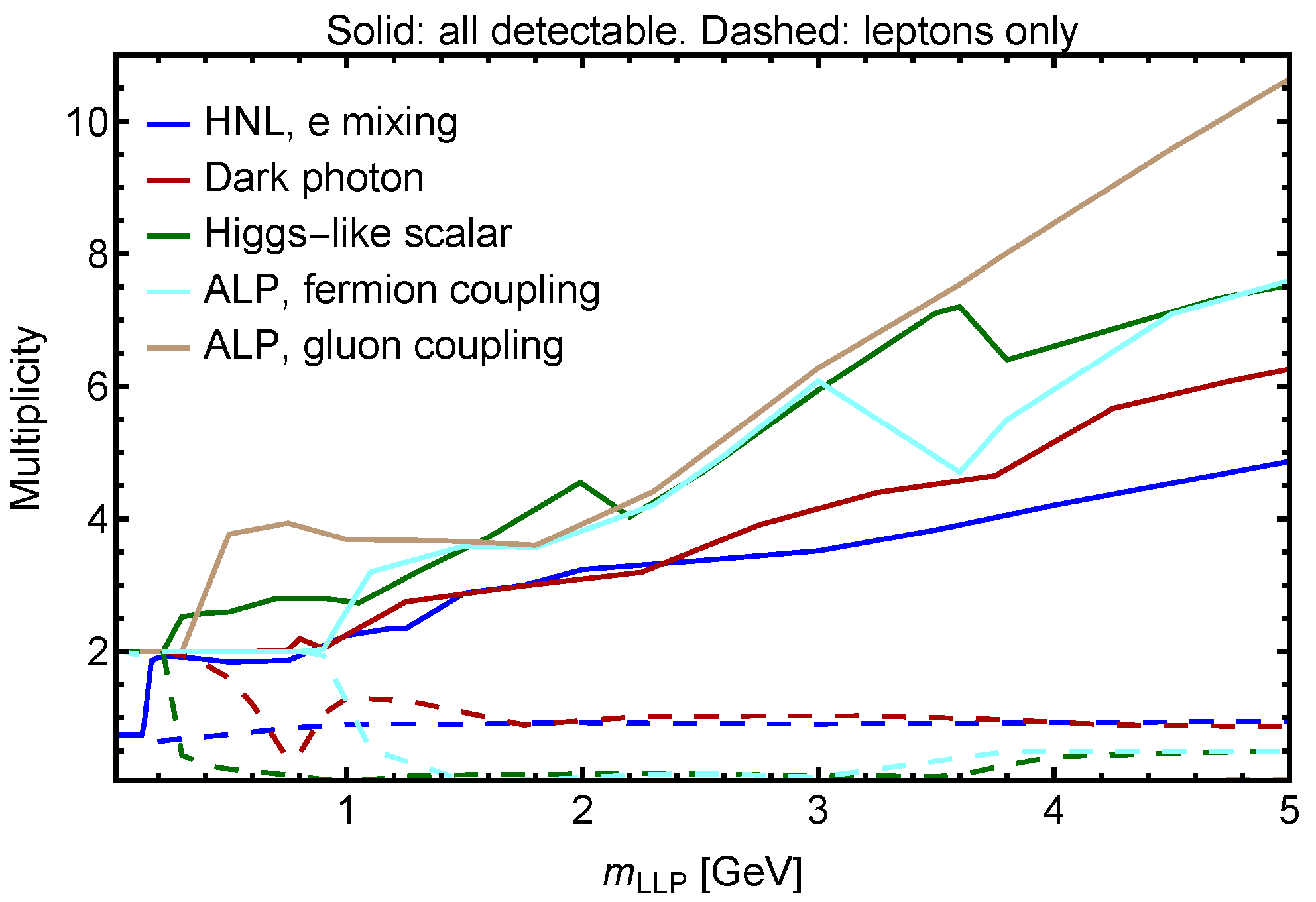
We compute the sensitivity curves of FACET and PREFACE in the plane “LLP mass m” versus “LLP coupling g to SM” requiring the number of events N events ( m , g ) 2.3 . That corresponds to the 90% CL exclusion limit under the assumption of no background. For the detection signature, we consider at least two tracks with a total zero electric charge within the coverage of the last detector plane. Depending on the background presence, other signatures may be used, such as searches for the di-muon vertex or large-multiplicity vertices, which is common for LLPs with mass m 1 GeV when multi-body hadronic decays become possible, as shown in Figure 17. We also require the energy of each of the tracks to be E > 1 GeV . The jumps in the lines are caused either by the behavior of the branching ratios (opening new decay modes, resonant enhancement of some decay probabilities), or by switching from the exclusive description of decays to the perturbative QCD description in the GeV mass range [31,32,33,34,35].
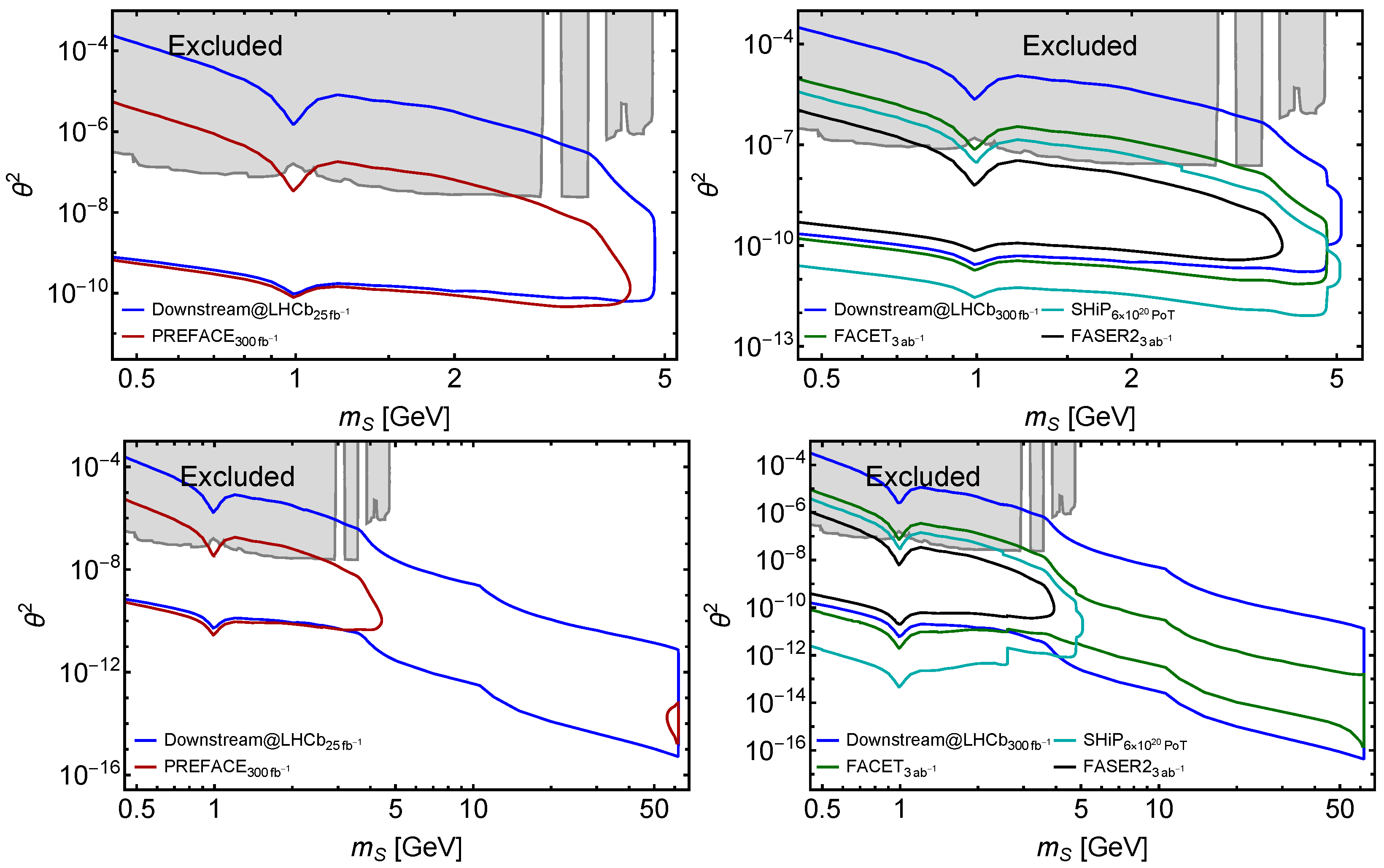
When presenting the sensitivity of PREFACE, in order to compare with other running or future experiments, we consider two plots for each LLP model, as can be seen in Figure 18, Figure 19 and Figure 20. In Figure 18, Figure 19 and Figure 20 (left), we consider near future projects including PREFACE, FASER, NA62 in the dump mode (denoted “NA62-dump” in what follows), and the downstream algorithm at LHCb [36], which is denoted “Downstream@LHCb” elsewhere below. We consider the integrated luminosities L = 300 fb 1 for the first two setups and L = 50 fb 1 for Downstream@LHCb. For NA62-dump, we assume 10 18 protons-on-target (PoT) corresponding to the luminosity accumulated until LHC Run 3, and use the description of the setup and the selection criteria from the lepton final state analysis from ref. [37], assuming that the same applies for hadronic states (see the discussion in ref. [38]). We take the sensitivity curves of FASER from ref. [13] and for the Downstream@LHCb from ref. [36], with the essential exception that we use the recent advances in describing the LLP phenomenology instead of the outdated descriptions considered in ref. [13].
In Figure 18, Figure 19 and Figure 20 (right), we show the experiments with the running time extended to the HL-LHC. These are: FACET, SHiP, where we assume 15-year running time from 2031 to 2046 [39], FASER2 (we take the FPF setup from ref. [27]) and the Downstream@LHCb, where the luminosities correspond to the full high luminosity runs ( L = 3 ab 1 for FACET and FASER2, and 300 fb 1 for LHCb). We show the NA62 curve assuming 10 18 PoT . We use the curves of SHiP from refs. [30,39]. We calculate the FASER2 curves using the SensCalc package, maintaining the same description of the phenomenology used in obtaining the sensitivities.
Not all experiments can provide detailed background studies, as achieved by SHiP, for instance, showing to be practically background-free; therefore, the results obtained here need to be updated once the backgrounds in each experiment are known better. Also, the overall detectors’ efficiencies are not considered for these comparisons, with the aim of understanding if the acceptance differences between FACET and PREFACE may be critical for the latter. This is not the case for the considered benchmark processes. We rely on real-time tracking to eliminate or reduce different kinds of backgrounds, and therefore, the efficiencies of these systems are expected to have an impact on PREFACE sensitivity.

4.2.1. Heavy Neutral Leptons

Let us start with the case of HNLs. We consider HNLs coupled to electron flavor; the case of other models is similar.
The phenomenology of HNLs is described in ref. [33]. There are three main production mechanisms: decays of D and B mesons, and decays of W bosons. The hierarchy of these modes is determined by the total amounts of produced mother particles: N D N B N W , as well as the kinematic threshold (Ds may only produce HNLs with mass below ( m D s m N m l ), where l denotes the lepton flavor with which the HNLs mix). As a result, decays of D dominate in the mass range m N m D , B decays in the mass range m D m N m B c , while at larger masses, only decays of W contribute.
Similar to other LLPs produced in the very forward direction, HNLs have mean energies typically a few hundred GeV. The energies of their decay products may exceed a few tens of GeV, as can be seen in Figure 21.
The sensitivity to HNLs is shown in Figure 22. The distribution of HNLs from D meson is narrower than the distribution of those from B, whereas light HNLs from Ws have the broadest distribution, because of the large enough W-boson mass. That affects the comparison between Downstream@LHCb, FASER2, FACET, and PREFACE, which have the strongest sensitivity among these four experiments for m N m B —the experiments combine the relative far-forward location with a large enough detector solid angle and a long decay volume. Downstream@LHCb has a larger solid angle and sensitivity than shorter-lived HNLs, thanks to a smaller distance to the decay volume, giving access to a mass domain above the B meson mass. However, it is of importance to remember the remarks made just above in this Section about the need of more detailed background studies for most of the searches, except SHiP and FASER.

4.2.2. Dark Photons

The phenomenology of dark photons V is described in refs. [31,38,40]. The dominant production modes for m V 1 GeV are decays of light pseudoscalar mesons π 0 , η , η , together with primary radiation processes, such as proton bremsstrahlung, final state radiation and production via mixing with vector mesons ρ 0 , ω , ϕ , and the Drell–Yan process. The decay channels are di-lepton and hadronic decays resembling ρ 0 / ω / ϕ -like modes at masses m V 2 GeV , and decays into jets at higher masses.
The proton bremsstrahlung production channel, which is one of the main production mechanisms of dark photons with mass around 1 GeV, suffers from severe theoretical uncertainties [40]. As studied in ref. [38], the sensitivities and constraints on dark photons in the mass range m V m π significantly depend on the bremsstrahlung flux. Here, we assume for illustration the “Baseline” description from ref. [38].
The parameter space of dark photons is shown in Figure 18. For the reasons outlined in Section 4.1, both PREFACE and FACET have limited potential to explore the parameter space of dark photons due to the off-axis placement and quite large distance from the interaction point to the decay volume. Downstream@LHCb has quite a small distance to the decay volume while FASER is located on-axis, both advantages. Other proposed setups at the LHC, such as SHIFT [41], may have sensitivity to dark photons as well.

4.2.3. Higgs-like Scalars

The 125 GeV Higgs boson h can decay to a pair of light Higgs-like scalars (dark Higgs) S with a relatively small branching fraction. Depending on the presence of the trilinear coupling h S S controlling the decay h S S , we distinguish between two models: BC4, with Br ( h S S ) = 0 , and BC5, where the branching ratio Br ( h S S ) = 0.01 is fixed to be at the boundary of the values accessible by the search for h invisible at the ATLAS and CMS experiments in the high luminosity phase [12].
The description of the phenomenology of the scalars can be found, e.g., in ref. [34]. The main production channel of S in the BC4 model is the decay of B mesons, originating from the flavor-changing neutral current operator b S + s . For the BC5 model, the dominant production is the decay of the Higgs bosons, h S S . The decay modes include di-lepton decays with μ + μ and τ + τ favored if kinematically accessible, as well as decays into hadrons. The hadronic decays completely dominate at masses m S 2 m π . In the mass range m S 2 GeV , there is significant theoretical uncertainty in the hadronic decays [42], coming from the lack of understanding of the contributions of the intermediate resonances to the di-pion and di-kaon decays. For the given study, we follow the description from ref. [43].
The sensitivities are shown in Figure 19. The BC4 case is quite similar to that of the ALPs coupled to fermions, as they share a similar production mode—decays of B mesons—as well as the Yukawa-like structure of the interactions mediating the decays. We do not show the sensitivity of FASER in Figure 19 (left) with the near-future experiments because it does not extend beyond the region of excluded parameter space [13]. In Figure 19 (bottom left), PREFACE exhibits two distinct exclusion regions, because the fraction of Higgs-like scalars from Higgs bosons increases with the scalar’s mass, which is maximal near the reaction threshold, causing the second smaller exclusion region.
For BC5, the production in the decays h S S becomes possible. It dominates the yield of produced scalars and makes it possible to probe scalar masses m B < m S < m h / 2 . Scalars from these decays have a broad angular distribution, so the event yield is expected to be larger at the experiments covering quite large solid angles. FASER2 does not have sensitivity to these masses, whereas Downstream@LHCb provides the best sensitivity in case of negligible background.
The sensitivity of PREFACE with the LHC Run 4 luminosity L = 300 fb 1 has two disconnected regions—below m S m B and at masses m S 50 GeV due to the mass dependence of the fraction of scalars from the decay h S S pointing to the PREFACE decay volume. If m S m h / 2 , the sensitivity is negligibly small, of the order of 10 4 . This feature is caused by the large p T m h 2 / 4 m S 2 gained from the Higgs mass, which makes the angular distribution of scalars more isotropic. Therefore, the main sensitivity comes from the production of S by B mesons. Once m S grows, p T ( S ) decreases and the fraction tends to 10 2 , resulting in more events.

4.2.4. ALPs Coupled to Fermions

Broadly considered models of ALPs assume that ALPs have universal coupling to fermions.A specific choice of the scale Λ at which the couplings are defined, Λ = 1 TeV , corresponds to the BC10 model [12]. This phenomenology of this model has been recently revised in ref. [35], where the missing production modes and hadronic decays of the ALPs are considered.
Similarly to the Higgs-like scalars, the main production channel of such ALPs is the decay of B mesons. The decay modes include di-lepton decays, as well as decays into hadrons dominating for ALP masses m a 1 GeV .
The parameter space of this model in terms of the ALP mass m a and the ALP coupling g Y , along with the sensitivity curves, is shown in Figure 20.
The ALPs produced by decays of B mesons have a broad transverse momentum distribution. Therefore, the experiments covering smaller solid angles, such as FASER, NA62-dump, and FASER2, have less acceptance than others covering larger angles, such as PREFACE and SHiP.
At the lower bound of sensitivity, the number of events behaves as g Y 4 , so a factor of 2 difference in the sensitivity curves of various experiments translates to a factor of 16 in the number of events.
At the upper bound of sensitivity, PREFACE shows less sensitivity than Downstream@LHCb, mainly because of its considerably farther distance—the decay volume is located at z = 100 m , compared to z = 1 m for Downstream@LHCb. At the lower bound, the experements are found to be of similar sensitivity. Overall, PREFACE is expected to provide an exceptional exploration potential for ALPs.
In the long-term future, FACET is designed to explore some larger parameter space, mainly because of the PREFACE off-axis placement, where the fluxes of many parent particles already start falling (as discussed in Section 4.1). PREFACE offers a better sensitivity than SHiP at the upper bound, as the typical momenta of the ALPs are considerably larger at the LHC. At the lower bound, SHiP is expected to be able to explore sensitively lower couplings, thanks to a considerably higher luminosity and large enough angular coverage. These features are largely independent of the model.

5. Experimental Program for PREFACE

A preliminary study of physics potential with the PREFACE geometry shows that some of the significant channels explored for the far-forward detectors are accessible to PREFACE with a sensitivity enhanced by the shorter distance from IP5 and longer fiducial volume with respect to FASER and FASER2, with a FoM more than an order of magnitude larger than FASER2 in the lifetime region of overlap, and essentially extending the lifetime coverage.

5.1. Considerations on PREFACE Apparatus

The PREFACE detectors can be optimized considering high-resolution tracking (TR) with real-time triggering capability, medium-high resolution calorimetry, and spectrometry with permanent magnets. The main issues are limited space in the LSS5 insertion region and quite large backgrounds, mainly from secondary interactions in the beam pipe and other materials.
Optimization criteria include a straight path from IP5 to PREFACE between 2 and 10 mrad; the PREFACE apparatus is designed to detect and measure neutral LLP particles produced at IP5, reaching the fiducial decay volume of PREFACE through about 200 λ int of Fe in the quadrupole triplets and dipoles of the LHC lattice. Decays of penetrating particles are measured with the PREFACE detectors behind the decay region.
To remove most background in a prompt trigger, tracks in the first tracker are projected upsteam to the front hodoscope/tracker, and if there is a corresponding hit, the track is ignored. If two or more tracks come from a common vertex on the beam pipe walls (pipe interactions) or upstream shielding, they are ignored. See details in the trigger criteria Section 5.3 below.

5.1.1. Decay Analysis

For simplicity, we consider two-body decays X e + e , μ + μ , h + h . The invariant mass of the two SM particles system is
M x 2 m 1 2 + m 2 2 + 2 E 1 E 2 ( 1 cos θ ) ,
where m and E denote masses and energies of the particles, and θ is the angle between the particles momenta direcions.
To accurately measure M x , one needs acceptable resolution δ E / E (the momenta p are only measured for muons) and d θ ; with a (conservative) space resolution for tracker (TR: δ x 200 μm; l 1 m), δ θ 0.2 mrad; for X e + e , the satisfactory angular resolution is complemented by the energy resolution ( δ E / E 0.15 / E ± 0.01 ) for showers in the EM calorimeter; for hadrons ( X h + h ), the energy resolution to be δ E / E 0.45 / E ± 0.02 (with, for example, CALICE EM and HAD calorimeter prototypes [44]), the availability of high-granularity calorimeter (HGCAL) modules improves the resolution. The HAD resolution is unsatisfactory at low energies, but the resolution increases with energy ( δ E / E 45% at 1 GeV/c; at 100 GeV/c, δ E / E 4.5%).

5.1.2. Muon Spectrometer with Permanent Magnets

For the muon channel X μ + μ , a relatively easy solution seems to be to use permanently magnetized bricks (Sm-Co, Nd-Fe-B, etc.) with the joint functions of bending the muon trajectories and filtering out hadrons and electrons. For a typical B·L ≈ 1 T·m and δ θ 0.2 mrad, a momentum resolution δ p / p 5.3 × 10 3 may be achieved, but the multiple scattering (MS) in the (Fe, X o = 1.76 cm) pile can deteriorate the resolution to about 25%, limiting the mass resolution of an LLP candidate decaying to μ + μ .
The nominal design has 2 m of magnetized iron between tracking stations sections of 0.5 m. The iron can be, in four block sections of 0.5 m (weight of about 2.2 tons/block) with thin tracking layers in between for improved muon track reconstruction. The average rms multiple scattering angle of 50 GeV/c muons is approximately 2.8 mrad, compared to a bending angle of 12 mrad, so the charge is quite well determined. The momentum resolution is only δ p / p 25%, limited by the multiple scattering, not by the spatial resolution of the tracker. The LHC beam is shielded from the relatively small fringe field by the pipe shield.

5.1.3. Alternative Air-Core Permanent Magnet

Maintaining the attractive features of permanent magnets (no power and no simple-cooling) and providing unobstructed space for the particles to be momentum-analyzed, an air-core design of the permanent magnet can be considered, as in other successful experiments where weight, minimal (or zero-) maintenance, high enough stability, and reliability are at a premium, like in FASER [16] and other projects. A Halbach array type of permanent magnet [45,46] offers an interesting alternative at relatively moderate cost.
For PREFACE, a possibility is to use an air-core permanent magnet (typically with Bx ≈ 0.5 T (vertical bend); aperture Dx ≈ 0.6 m, Dy ≈ 0.8 m, length L ≈ 2 m). This results in B·L ≈ 1 T·m (providing a bending angle of 3 mrad at 100 GeV/c), with minimal multiple scattering contributions.
Such a solution allows a rearrangement of the apparatus by moving the magnet forward between the two tracking stations and moving the calorimeters backward, with an additional absorber and detection stage behind to tag muons. In this configuration, the setup to be optimized for many more benchmark channels, involving X e + e , μ + μ , and h + h , as well as more complicated (multi-body) signatures. Having the magnet before the calorimeters makes it possible to improve the M X measurement and exploit their complementary precisions for low- and high-energy particles.

5.2. Remarks on the PREFACE Setup

In this paper, we have addressed the possibility of installing and operating the PREFACE apparatus in the region of the LHC tunnel between the D1 and TAXN in the long straight section downstream of IP5, taking into account the severe constraints on space, services, and radiation in that location. We have profited from the ground-breaking work studying the feasibility of the FACET project, designed specifically in this location in order to allow a strong synergy with the CMS experiment in choice of equipment technologies, operating services and technical support, and event selection and physics measurements.
PREFACE stems from an opportunistic acceptance of the FACET scenario anticipated for LHC Run 5 but not for Run 4, without the enlarged beam pipe, and avoiding the highest backgrounds in the horizontal plane. To accommodate the beam pipe configuration for Run 4, it is necessary to restrict the coverage to above the pipe. This region is quite less affected by charged particles swept horizontally by D1, and allows additional shielding of interactions in the beam pipe. Unlike the full-azimuthal coverage of FACET, the PREFACE detectors can be moved vertically if necessary to minimize backgrounds without reducing the solid angle.
The experimental configuration for PREFACE is not fully finalized; as mentioned in Appendix A, additional work need to be engaged in order to improve the setup for PREFACE and its Geant4 description, to address in more detail crucial questions on compatibility with the HL-LHC severe tunnel backgrounds. Together with the survey of benchmark processes given in this paper, such upgraded simulation could evolve into more detailed case studies of LLP searches, for better appreciating PREFACE capability to identify and measure BSM signatures, while keeping SM backgrounds low and manageable.
Essential for PREFACE is the requirement to use high-quality tracking with real-time selection of tracks for suppressing residual interactions from the beam pipes, for identifying entering charged particles, and for reconstructing topologically interesting decay signatures. Interactions (for example, of neutrons and K 0 ) on air in the fiducial decay volume have a different topology and may be largely rejected by a higher level trigger, possibly using AI.

5.3. Trigger Criteria

Since, at high luminosity, all bunch crossings to have tracks in PREFACE, track reconstruction and selection (with AI assistance) at the trigger level is essential to reject entering charged particles and tracks from interactions on the beam pipe and other materials.
Using the results from Geant4 simulations, some of these criteria may be tested for each bunch crossing (every 25 ns):
  • The slope of particle tracks is a powerful diagnostic to reject hits on the beam pipes. Tracks with high polar angles, tan θ > 0.1 , can be ignored; those tracks are secondary particles, mostly from scattering in the beam pipes and the pipe shield.
  • Any tracks extrapolated upstream to a hit in the front tracker to be ignored;
  • We require at least two of the remaining charged particles to have a vertex in the decay volume.
The Fluka simulation list identified particles at a score plane (100 m from IP5) with their previous history recorded, whether they come from the primary pp collision in IP5, or from subsequent interactions. These different categories may be used to test the trigger criteria concerning not only the pipe interactions, but also pointing back to the primary collision.
At the calorimeter, the simulated (background) particles have maximum energies less than 10, 50, 20, and 20 GeV, for electrons, muons, pions, and protons, respectively. For neutrals, maximum energies are less than 10 GeV and 20 GeV for photons and neutrons, respectively. Moderate cuts on the calorimeter signals helps in effectively cutting backgrounds. As discussed Section 5.1.3 above, while a permanent magnet is practical to identify muons and measure their charge, the momentum resolution is limited by MS. An air-core permanent magnet may be preferable to measure the momenta of all charged particles in PREFACE.
In LHC Run 4 with not less than 100 inelastic pp collisions producing quite some background tracks in PREFACE per bunch crossing, triggering on rare LLP decays is a challenge, but it is not a priori excluded.
In the search for X c + c ¯ as an example, we develop a fast trigger based on
  • at least one high-momentum muon tracks and/or at least one high-energy electron showers with quite small angles with respect to the beams (“high” refers to means above 100 GeV but tuneable);
  • at least two tracks in the tracker that were not detected in the front tracker at the beginning of the decay region, with a distance of closest approach below 200 μm at a point inside the fiducial decay region; and
  • a neural net (machine learning/AI) rejecting most interactions on the beam-pipe or shielding while selecting decay candidates.
The Level-1 trigger must give an acceptable rate without dead time, and at a higher level (or off-line), LLP candidates can be selected. It has not yet been discussed if PREFACE could be considered as a CMS subsystem, and in particular, if the PREFACE trigger might be integrated with the CMS one; in such a case, it should be well inside the CMS design latencies and use a relatively small fraction of the available rates at each trigger level.
Note that there are no SM neutral particles with mass above 1.2 GeV/ c 2 that can decay to charged particles in the fiducial volume, and those with lower mass ( K 0 , Λ 0 ) are produced in shielding, typically with quite low momentum.

5.4. Tracking, Timing, and Calorimetry

From the discussions in this paper, and the examples below, one can see that PREFACE relies essentially on a refined real-time tracking capability, as foreseen for HL-LHC, for example, by the CMS detector. Other fundamental functions such as timing for particle identification and calorimetry, as emphasized earlier, to highly profit from state-of-the-art technologies, such as low gain avalanche diode (LGAD) and Si-calorimetry, parts of the CMS detector upgrades. The number of components for such systems in PREFACE corresponds to a few percent of the CMS upgrade detectors.

5.5. Search for X τ + τ , c c ¯ , b b ¯

A trigger able to select events with 2 tracks including one or more electrons or muons, coming from a common vertex in the fiducial decay volume, enables a search for LLPs in the mass range 4 M 20 GeV. These are preferred decay channels for a scalar (dark Higgs) in that mass range. The fraction of τ decays to an electron or muon is 35%, similar to that of D ± mesons. Most pairs of charm and B mesons have additional charged tracks, so such a trigger can have quite a high efficiency. A full simulation with acceptances is under study.
SM particle decays from K 0 and strange baryons have lower masses and are quite well distinguished, and are practical for calibration of mass scales and for testing particle-type identification. Higher flavor particles, J / ψ , Υ , etc. are all too short-lived to reach the fiducial volume, but can provide a control sample of e + e and μ + μ pairs if tracks in the upstream tracker are accepted. Their fluxes, as well as those of K 0 and Λ 0 , can also provide helpful tests of shower simulation programs like Fluka.
Another background is from interactions of high-energy neutrons and K 0 in air, since unlike FACET, PREFACE does not have a vacuum decay volume. This background can be reduced with a helium bag or a thin-walled tank with air at a reduced pressure. However, such interactions are distinctly different from LLP decays, and most may be rejected even in a trigger (this is potentially a promising application of AI).

6. Conclusions

A search for new long-lived particles produced in the very forward direction, 2 θ 10 mrad, at the LHC and penetrating above 30 m of iron absorber before decaying to SM particles appears to be feasible, provided several conditions can be met. In particular, portals with a mass greater than a few GeV decaying to τ + τ , c c ¯ , and b b ¯ and inaccessible at fixed target experiments may be produced at the LHC, waiting for their discovery. The FACET project requires an expanded beam pipe and a vacuum decay region, which is not feasible before Run 5 (not before 2034). We describe PREFACE, which does not require any change to the LHC beam pipe and could in principle be operational in Run 4. The solid angle is the same as that of FACET (of about 0.64 m 2 ) but the detectors are above the beam pipe, avoiding the highest background regions to the left and right of the beams. A shielding plate between the beam pipe and the detectors gives a further reduction in background from beam halo particles showering in the pipe. The minimal set of detectors is a precision tracking system in the magnetic field-free region able to select and trigger on vertices in the decay region above the pipe. This is followed by a permanent magnet (with no power, cables, or cooling needed) to measure and trigger on muons. Adding an electromagnetic calorimeter for electrons and photons is essential (typical energies for electrons from LLP decays are considerably higher than from background showers), and a hadron calorimeter are highly required.
At the front of the fiducial decay region, a tracker is considered to tag incoming background tracks, with, optionally, a fast-timing hodoscope, which can incidentally provide valuable information, for example, for testing Fluka simulations of particle fluxes.
Some key issues for further study are the radiation levels and background minimization, discrimination at trigger level (AI is potentially a key component) between decays of candidate LLPs, SM decays (for example, K 0 , Λ 0 ), and interactions. PREFACE to be a first feasibility demonstration of using this so far unexploited very forward zone with 80 m z 120 m at the LHC, while initiating a generic search for portals in a new region of parameter space.

Author Contributions

Conceptualization, A.P., S.O. and M.G.A.; methodology, B.H., A.P., M.O. and M.G.A.; software, B.H., M.O. and O.A.; validation, B.H., M.O. and O.A.; formal analysis, B.H. and M.O.; investigation, B.H., M.O. and A.P.; data curation, B.H., M.O. and O.A.; writing—original draft preparation, B.H., S.O., A.P., M.O. and M.G.A.; writing—review and editing, B.H., A.P., S.O. and M.G.A.; visualization, B.H., M.O., A.P. and O.A.; supervision, S.O., A.P. and M.G.A.; project administration, B.H., A.P. and S.O.; funding acquisition, S.O. and A.P. All authors have read and agreed to the published version of the manuscript.

Funding

This work was supported in part by the US Department of Energy under grant DE-SC0010113. This study was partly funded by the Scientific Research Projects Coordination Unit of Istanbul University, project number FUA-2022-39051, and was also supported by Turkish Energy, Nuclear and Mining Research Agency (TENMAK), project number 2025TENMAK(CERN)A5.H3.F2-07.

Data Availability Statement

This paper concerns simulation studies and no experimental data were collected or analyzed in this study. The simulated data supporting the conclusions of this article can be made available by the authors on request.

Acknowledgments

PREFACE is based on the FACET project, being a study of the possibility of a version of FACET compatible with the LHC beam pipe and infrastructure already in Run 4, and we acknowledge all members of the FACET group for their contributions. We acknowledge valuable contributions from LHC staff, especially Francesco Cerutti, Jean-Pierre Corso, Julie Coupard, Paolo Fessia, and Marta Sabate Gilarte.

Conflicts of Interest

The authors declare no conflicts of interest.

Abbreviations

The following abbreviations are used in this manuscript:
AIartificial intelligence
ALICEA Large Ion Collider Experiment
ALPaxion-like particle
ATLASA Toroidal LHC ApparatuS
BCbenchmark case
BSMbeyond the SM
Bxmagnetic field vertical bend
B·Lmagnetic field times length
CALICECAlorimeter for the LInear Collider Experiment
CERNthe European Organization for Nuclear Research
CLconfidence level
CMSCompact Muon Solenoid
CPcorrector package
DAQdata acquisition
DFXDesign, Fabrication, and eXamination (unit)
DPdark photon
D1(2)dipole magnet 1 (2)
D1(2)L/RD1(2) left/right
Dx, Dyx, y apertures
EMelectromagnetic
FACETForward-Aperture CMS ExTension
FASERForwArd Search ExpeRiment
FlukaFluktuierende Kaskade
FoMfigure-of-merit
FPFForward Physics Facility
GeantGEometry ANd Tracking
HADhadronic (calorimeter)
HGCALHigh-Granualty CALorimeter
HL-LHChigh-luminocity LHC
HNLheavy neutral lepton
IDidentity
IPinteraction point
LGADlow gain avalanche diode
LHCLarge Hadron Collider
LHCb (LHC-B)LHC beauty
LLPlong-lived particle
LSS5long straight section at IP5
L1, L6first, sixth silicon tracker
MSmultiple scattering
NAnorth area
PBCphysics beyond colliders
PIDparticle identifier
PoTproton-on-target
PREFACEPionner Rare-Event Apparatus for Collider Experiments
QCDquantum chromodynamics
Q1–Q4quadrupole magnet 1–4
R571LHC tunnel hall name
rmsroot mean square
SHiPSearch for Hidden Particle
SMStandard Model
Std Devstandard deviation
TAXNtarget neutral beam absorber
TAXStarget absorber for secondary particles
TCLXtarget collimator long with increased cross section
TCLMBtargets collimators loss monitoring block
TCTtertiary collimator
TIDtotal ionizing dose
TOFtime-of-flight
TRtracking
UJ57LHC tunnel hall name
ZDCZero Degree Calorimeter

Appendix A. Future Studies in Progress

  • Optimize shielding design to minimize radiation doses and track multiplicity. Investigate available radiation-hard calorimeters and trackers with adequate performance. Design magnet optimizing length to minimize hadron track leakage. Design tracking in front of the fiducial decay region with (optional) timing for particle ID of backgrounds (and testing Fluka simulations).
  • Calculate acceptance for X e ± , μ ± (+ anything) decays as a function of M ( X ) , p T , p z . Calculate muon charge sign assignment and momentum resolution δ p / p versus p, and use of calibration channels, for example, J / ψ e + e , μ + μ (from shielding).
  • Design track-based trigger on vertices. Investigate AI trigger classifying events as X candidates, SM decays, or interactions.
  • Design supports and infrastructure, including signals and DAQ, cables, etc. People, timeline, costs, etc.

References

  1. Alimena, J.; Beacham, J.; Borsato, M.; Cheng, Y.; Vidal, X.C.; Cottin, G.; Curtin, D.; De Roeck, A.; Desai, N.; Evans, J.A.; et al. Searching for long-lived particles beyond the Standard Model at the Large Hadron Collider. J. Phys. G 2020, 47, 090501. [Google Scholar] [CrossRef]
  2. Bawa, H. [on behalf on the ATLAS and CMS Collaborations]. Recent results from Beyond Standard Model (BSM) searches at LHC. Nucl. Part. Phys. Proc. 2015, 267–269, 277–286. [Google Scholar] [CrossRef]
  3. Policicchio, A. [on behalf of the ATLAS Collaboration]. BSM searches in ATLAS. PoS 2015, CORFU2014, 063. [Google Scholar] [CrossRef]
  4. Aberle, O.; Béjar Alonso, I.; Brüning, O.; Fessia, P.; Lamont, M.; Rossi, L.; Tavian, L.; Zerlauth, M. High-Luminosity Large Hadron Collider (HL-LHC). Technical Design Report; CERN Report CERN-2020-010; CERN: Geneva, Switzerland, 2020. [Google Scholar] [CrossRef]
  5. Brüning, O.; Rossi, L. The High-Luminosity Large Hadron Collider. Nat. Rev. Phys. 2019, 1, 241–243. [Google Scholar] [CrossRef]
  6. Dainese, A.; Mangano, M.; Meyer, A.B.; Nisati, A.; Salam, G.; Vesterinen, M.A. Report on the Physics at the HL-LHC, and Perspectives for the HE-LHC; CERN Report CERN-2019-007; CERN: Geneva, Switzerland, 2019. [Google Scholar] [CrossRef]
  7. Shchutska, L. [on behalf of the CMS Collaboration]. Prospects for BSM searches at the high-luminosity LHC with the CMS detector. Nucl. Part. Phys. Proc. 2016, 273–275, 656–661. [Google Scholar] [CrossRef]
  8. Rühr, F. [on behalf of the ATLAS Collaboration]. Prospects for BSM searches at the high-luminosity LHC with the ATLAS detector. Nucl. Part. Phys. Proc. 2016, 273–275, 625–630. [Google Scholar] [CrossRef]
  9. Fischer, O.; Mellado, B.; Antusch, S.; Bagnaschi, E.; Banerjee, S.; Beck, G.; Belfatto, B.; Bellis, M.; Berezhiani, Z.; Blanke, M.; et al. Unveiling hidden physics at the LHC. Eur. Phys. J. C 2022, 82, 665. [Google Scholar] [CrossRef]
  10. Mitsou, V.A. Hunting new physics with ATLAS. EPJ Web Conf. 2018, 182, 02089. [Google Scholar] [CrossRef]
  11. Alekhin, S.; Altmannshofer, W.; Asaka, T.; Batell, B.; Bezrukov, F.; Bondarenko, K.; Boyarsky, A.; Choi, K.-Y.; Corral, C.; Craig, N.; et al. A facility to search for hidden particles at the CERN SPS: The SHiP physics case. Rep. Prog. Phys. 2016, 79, 124201. [Google Scholar] [CrossRef]
  12. Beacham, J.; Burrage, C.; Curtin, D.; De Roeck, A.; Evans, J.; Feng, J.L.; Gatto, C.; Gninenko, S.; Hartin, A.; Irastorza, I.; et al. Physics beyond colliders at CERN: Beyond the Standard Model working group report. J. Phys. G 2020, 47, 010501. [Google Scholar] [CrossRef]
  13. Antel, C.; Battaglieri, M.; Beacham, J.; Boehm, C.; Buchmüller, O.; Calore, F.; Carenza, P.; Chauhan, B.; Cladè, P.; Coloma, P.; et al. Feebly-interacting particles: FIPs 2022 Workshop Report. Eur. Phys. J. C 2023, 83, 1122. [Google Scholar] [CrossRef]
  14. Batell, B.; Blinov, N.; Hearty, C.; McGehee, R. Exploring dark sector portals with high intensity experiments. arXiv 2022, arXiv:2207.06905. [Google Scholar] [CrossRef]
  15. Lu, C.-T.; Lv, H.; Shen, W.; Wu, L.; Zhang, J. Probing dark QCD sector through the Higgs portal with machine learning at the LHC. J. High Energy Phys. 2023, 2023, 187. [Google Scholar] [CrossRef]
  16. Abreu, H.; et al. [FASER Collaboration] The FASER detector. J. Instrum. 2024, 19, P05066. [Google Scholar] [CrossRef]
  17. Feng, J.L.; Kling, F.; Reno, M.H.; Rojo, J.; Soldin, D.; Anchordoqui, L.A.; Boyd, J.; Ismail, A.; Harland-Lang, L.; Kelly, K.J.; et al. The Forward Physics Facility at the High-Luminosity LHC. J. Phys. G 2023, 50, 030501. [Google Scholar] [CrossRef]
  18. Cerci, S.; Sunar Cerci, D.; Lazic, D.; Landsberg, G.; Cerutti, F.; Sabaté-Gilarte, M.; Albrow, M.G.; Berryhill, J.; Green, D.R.; Hirschauer, J.; et al. FACET: A new long-lived particle detector in the very forward region of the CMS experiment. J. High Energy Phys. 2022, 2022, 110. [Google Scholar] [CrossRef]
  19. Penzo, A. [on behalf of FACET Team]. FACET: Forward Aperture CMS ExTension. Talk at the Thirteenth Workshop of the LLP Community (LLP13) on Searching for Long-Lived Particles at the LHC and Beyond, 19–23 June 2023, CERN, Geneva, Switerland. 2023. Available online: https://indico.cern.ch/event/1216822/timetable/ (accessed on 25 May 2025).
  20. Feng, J.L.; Galon, I.; Kling, F.; Trojanowski, S. ForwArd Search ExpeRiment at the LHC. Phys. Rev. D 2018, 97, 035001. [Google Scholar] [CrossRef]
  21. Arduini, G.; Barranco, J.; Bertarelli, A.; Biancacci, N.; Bruce, R.; Brüning, O.; Buffat, X.; Cai, Y.; Carver, L.R.; Fartoukh, S.; et al. High Luminosity LHC: Challenges and plans. J. Instrum. 2016, 11, C12081. [Google Scholar] [CrossRef]
  22. Grachov, O.; Murray, M.; Wood, J.; Onel, Y.; Sen, S.; Yetkin, T. [on behalf of HCAL-CMS Collaboration]. Commissioning of the CMS zero degree calorimeter using LHC beam. J. Phys. Conf. Ser. 2011, 293, 012040. [Google Scholar] [CrossRef]
  23. Albrow, M.; et al. [The CMS and TOTEM Collaborations] CMS–TOTEM Precision Proton Spectrometer. Technical Design Report; CERN Report CERN-LHCC-2014-021; CERN: Geneva, Switzerland, 2014; Available online: https://cds.cern.ch/record/1753795 (accessed on 25 May 2025).
  24. Agostinelli, S.; et al. [Geant4 Collaboration] Geant4—A simulation toolkit. Nucl. Instrum. Meth. Phys. Res. A Accel. Spectrom. Detect. Assoc. Equip. 2003, 506, 250–303. [Google Scholar] [CrossRef]
  25. Ballarini, F.; et al. [The FLUKA Collaboration] The FLUKA code: Overview and new developments. EPJ Nucl. Sci. Technol. 2024, 10, 16. [Google Scholar] [CrossRef]
  26. Fessia, P.; et al. [EN STI R2E Team] HL-LHC Integration Boundary Conditions at IR5 for Any Installation between DFX and TAXN. Talk at the FMS–LLP Search General Meeting, 1 October 2020; CERN, Geneva, Switerland. Available online: https://indico.cern.ch/event/959035/ (accessed on 25 May 2025).
  27. Diwan, M.V.; et al. [FPF Working Groups] Forward Physics Facility; BNL Report BNL-224243-2023-COPA; Brookhaven National Laboratory (BNL): Upton, NY, USA, 2023. Available online: https://www.osti.gov/biblio/1972463 (accessed on 25 May 2025).
  28. Lerner, G.; Sabaté Gilarte, M.; Alía, R.G.; Cerutti, F.; Tsiganis, A. HL-LHC Radiation Levels on Alignment Systems in the LSS of IP1–IP5. Presentation at the Review of HL-LHC Alligment and Internal Metrology (WP15.4) Meeting, 26–28 August, 2019, CERN, Geneva, Switzerland. 2019. Available online: https://indico.cern.ch/event/831552/contributions/3484724/ (accessed on 25 May 2025).
  29. Berlin, A.; Kling, F. Inelastic dark matter at the LHC lifetime frontier: ATLAS, CMS, LHCb, CODEX-b, FASER, and MATHUSLA. Phys. Rev. D 2019, 99, 015021. [Google Scholar] [CrossRef]
  30. Ovchynnikov, M.; Tastet, J.-L.; Mikulenko, O.; Bondarenko, K. Sensitivities to feebly interacting particles: Public and unified calculations. Phys. Rev. D 2023, 108, 075028. [Google Scholar] [CrossRef]
  31. Ilten, P.; Soreq, Y.; Williams, M.; Xue, W. Serendipity in dark photon searches. J. High Energy Phys. 2018, 2018, 4. [Google Scholar] [CrossRef]
  32. Aloni, D.; Soreq, Y.; Williams, M. Coupling QCD-scale axionlike particles to gluons. Phys. Rev. Lett. 2019, 123, 031803. [Google Scholar] [CrossRef]
  33. Bondarenko, K.; Boyarsky, A.; Gorbunov, D.; Ruchayskiy, O. Phenomenology of GeV-scale heavy neutral leptons. J. High Energy Phys. 2018, 2018, 32. [Google Scholar] [CrossRef]
  34. Boiarska, I.; Bondarenko, K.; Boyarsky, A.; Gorkavenko, V.; Ovchynnikov, M.; Sokolenko, A. Phenomenology of GeV-scale scalar portal. J. High Energy Phys. 2019, 2019, 162. [Google Scholar] [CrossRef]
  35. Dalla Valle Garcia, G.; Kahlhoefer, F.; Ovchynnikov, M.; Zaporozhchenko, A. Phenomenology of axionlike particles with universal fermion couplings revisited. Phys. Rev. D 2024, 109, 055042. [Google Scholar] [CrossRef]
  36. Gorkavenko, V.; Jashal, B.K.; Kholoimov, V.; Kyselov, Y.; Mendoza, D.; Ovchynnikov, M.; Oyanguren, A.; Svintozelskyi, V.; Zhuo, J. LHCb potential to discover long-lived new physics particles with lifetimes above 100 ps. Eur. Phys. J. C 2024, 84, 608. [Google Scholar] [CrossRef]
  37. Cortina Gil, E.; et al. [NA62 Collaboration] Search for leptonic decays of dark photons at NA62. Phys. Rev. Lett. 2024, 133, 111802. [Google Scholar] [CrossRef]
  38. Kyselov, Y.; Ovchynnikov, M. Searches for long-lived dark photons at proton accelerator experiments. Phys. Rev. D 2025, 111, 015030. [Google Scholar] [CrossRef]
  39. Albanese, R.; et al. [SHiP Collaboration]; Aberle, O.; et al. [BDF Working Group] BDF/SHiP at the ECN3 High-Intensity Beam Facility. Proposal; CERN Report CERN-SPSC-2023-033/SPSC-P-369; CERN: Geneva, Switerland, 2023; Available online: https://cds.cern.ch/record/2878604/ (accessed on 25 May 2025).
  40. Foroughi-Abari, S.; Reimitz, P.; Ritz, A. A closer look at dark vector splitting functions in proton bremsstrahlung. arXiv 2024, arXiv:2409.09123. [Google Scholar] [CrossRef]
  41. Niedziela, J. SHIFT@LHC: Searches for new physics with shifted interaction on a fixed target at the Large Hadron Collider. J. High Energy Phys. 2020, 2020, 204. [Google Scholar] [CrossRef]
  42. Blackstone, P.J.; Tarrús Castellà, J.; Passemar, E.; Zupan, J. Hadronic decays of a Higgs-mixed scalar. arXiv 2024, arXiv:2407.13587. [Google Scholar] [CrossRef]
  43. Winkler, M.W. Decay and detection of a light scalar boson mixing with the Higgs boson. Phys. Rev. D 2019, 99, 015018. [Google Scholar] [CrossRef]
  44. Yoshioka, T. Performance of the CALICE calorimeters. PoS 2013, ICHEP2012, 502. [Google Scholar] [CrossRef]
  45. Halbach, K. Design of permanent multipole magnets with oriented rare earth cobalt material. Nucl. Instrum. Meth. 1980, 169, 1–10. [Google Scholar] [CrossRef]
  46. Blümler, P.; Soltner, H. Practical concepts for design, construction and application of Halbach magnets in magnetic resonance. Appl. Magn. Reson. 2023, 54, 1701–1739. [Google Scholar] [CrossRef]
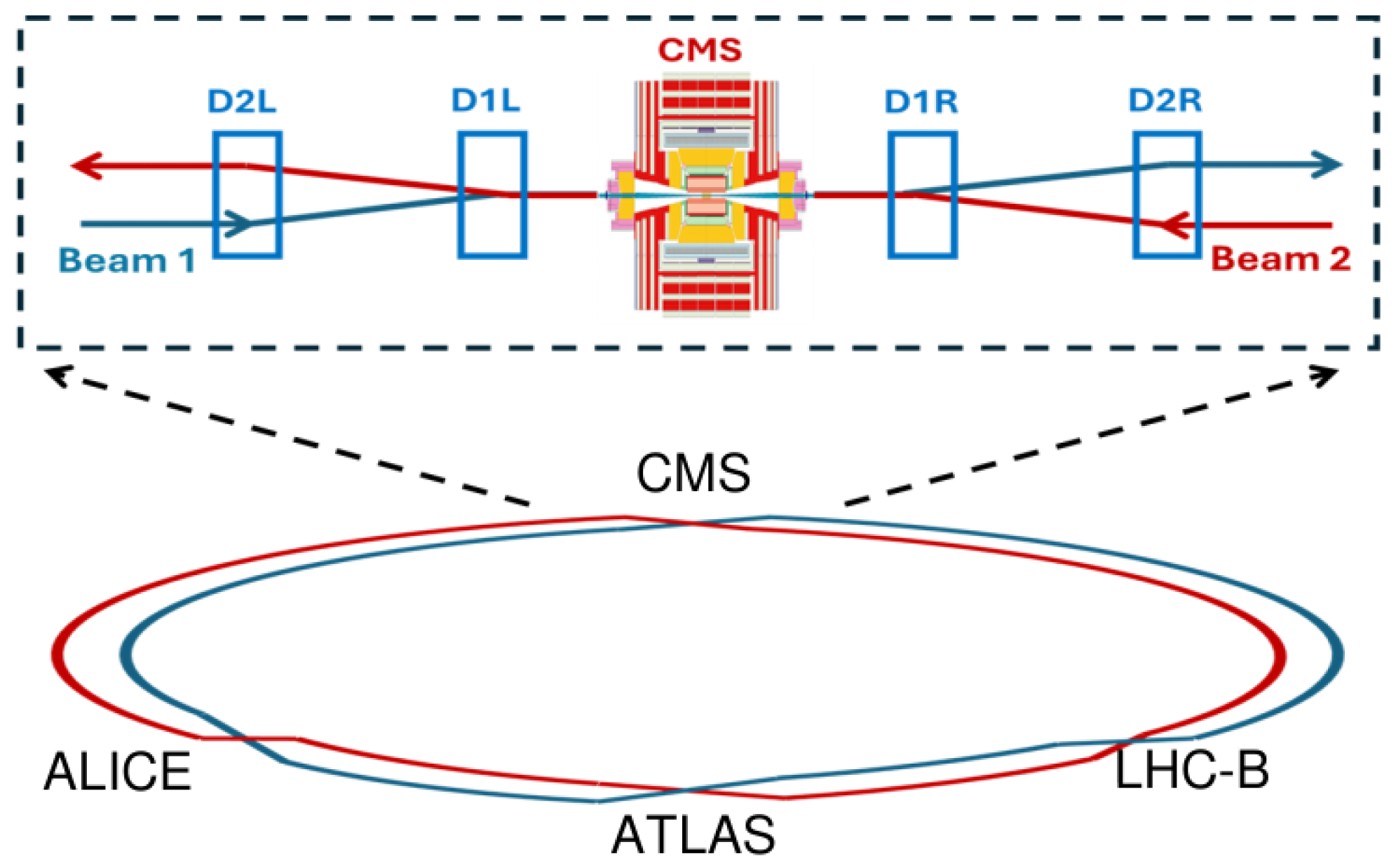
Figure 1. Sketch of the LHC ring, with the four major experiments studying pp, pA, and AA collisions (actually, A is Pb at LHC but lighter nuclei are possible).
Physics 07 00033 g001
Figure 2. Overall layout downstream of the IP5 region (schematic). The incoming (blue) and outgoing (red) beams are in a common beam pipe between the beam separation dipole D1 and the TAXN. The light regions show the 14.2- σ (rms) beam envelope [21]. While s denotes the beam axis here, z is used to represent the beam axis throughout this paper.
Physics 07 00033 g002
Figure 3. Schematic layout of the proposed FACET spectrometer.
Physics 07 00033 g003
Figure 4. Distribution in the transverse plane of negative (left) and positive (right) particles at z = 100 m for particles originating at the interaction vertex at IP5. Colors show the flux in ( mm ) 2 for 140 pp collisions. “Std Dev” in the statistics box stands for “standard deviation”.
Physics 07 00033 g004
Figure 5. Charged particles produced at IP5 and reaching z = 100 m; x y -distribution (left) and z of the last interaction points of those particles (right). The three circles represent, respectively, the beam pipe ( r = 12.5 cm) after z 108 m, while the other two ( r = 18 cm, r = 45 cm) are the limits of FACET coverage. Colors show the flux in ( cm ) 2 for 140 pp collisions.
Physics 07 00033 g005
Figure 6. Position distributions (xy) of charged particles (e, μ , π , p, K) hits at first silicon tracker (left) and the calorimeter (right) are shown for the FACET detector. The beam pipe inside the trackers generates secondary particles. The colored scale shows the flux in ( cm ) 2 (140 pp)−1. The maximum flux is lower by an order of magnitude after the calorimeter.
Physics 07 00033 g006
Figure 7. Azimuthal angle distributions of (left) charged particle (e, μ , π , p, K) and (right) neutral particle ( γ , n, K L 0 ) hits at different detector layers for FACET detector. The azimuthal angle region between the dashed lines corresponds to the PREFACE acceptance, excluding the relatively high flux azimuthal angle to the right.
Physics 07 00033 g007
Figure 8. Layout of the LSS5 region between the beam separation dipole D1 and the TAXN absorber [26].
Physics 07 00033 g008
Figure 9. Cross section from 120 m downstream of the IP5, LSS5, LHC tunnel [26].
Physics 07 00033 g009
Figure 10. Schematic representation of the parameters defining a Figure of Merit for a forward LLP search experiment. See text for details.
Physics 07 00033 g010
Figure 11. Figure of Merit for the PREFACE detector and for FACET, FASER, and FASER2.
Physics 07 00033 g011
Figure 12. Layout of the PREFACE setup (not to scale).
Physics 07 00033 g012
Figure 13. Geometry of detectors downstream of the decay volume for the Geant4 PREFACE simulation.
Physics 07 00033 g013
Figure 14. Flux of different particle types comparing three conditions: (left) FACET, (middle) PREFACE without pipe shield, and (right) PREFACE with pipe shield. The reduction is about an order of magnitude (left to right) for the most relevant types of background (electromagnetic and hadronic components). This is achieved by going from the cylindrical FACET geometry to the rectangular PREFACE geometry, in the upper quadrant ( ϕ [ π / 4 , 3 π / 4 ] ), excluding the 4 o’clock ( ϕ 7 π / 4 ) hotspot.
Physics 07 00033 g014
Figure 15. Total Ionizing Dose versus distance from IP5 60 cm above the beamline, estimated with Optics v1.3 of Fluka for the total HL-LHC run (4000 fb 1 ). The TID for PREFACE (z = 100 m–120 m) in Run 4 (300 fb 1 ) is estimated to be of 26 kGy, without the proposed pipe shield. These levels of radiation are not excessive for the technologies foreseen for PREFACE detectors.
Physics 07 00033 g015
Figure 16. Solid angle distributions d f / d ( cos θ ) of various LLPs: dark photons (DP), HNLs, and Higgs-like scalars S with (BC5) and without (BC4) trilinear couplings h S S [12], showing the polar angular coverage of FACET and PREFACE produced using the SensCalc package [30].
Physics 07 00033 g016
Figure 17. Average particle multiplicity per decay of several LLPs in the GeV mass range, for the models considered in Table 2. The solid lines show the total particle multiplicity, while the dashed lines show only the charged lepton multiplicity. Produced using the SensCalc [30] package.
Physics 07 00033 g017
Figure 18. Sensitivities of PREFACE and FACET to dark photons generated using SensCalc package for SHiP, NA62-dump, and Downstream@LHCb, and digitized from ref. [13] for FASER and FASER2, for the near-future projects (left) and for the 15-year running time extended to the HL-LHC (right); see text for details. The constraints on the dark photon parameter space are from refs. [13,38]. Small islands of sensitivity at m V 0.75 MeV are caused by dark photons mixing with strongly produced ρ 0 mesons.
Physics 07 00033 g018
Figure 19. Sensitivities of FACET and PREFACE to Higgs-like scalars: model without h S S coupling BC4 [12] (top) and model with h S S coupling fixed such that Br ( h S S ) = 0.01 (bottom) generated using the SensCalc package [30], for the near-future projects (left) and for the 15-year running time extended to the HL-LHC (right); see text for details. The domain constrained by past experiments are from ref. [13]. Here, θ is the mixing angle of the Higgs-like scalars.
Physics 07 00033 g019
Figure 20. Sensitivity of FACET and PREFACE to the ALPs coupled to fermions in the plane ALP mass m a versus ALP coupling g Y , for consistency, all computed using the SensCalc package [30], with some of the constrained regions been revised to reflect updated phenomenology, for the near-future projects {(left) and for the 15-year running time extended to the HL-LHC (right); see text for details. The description of the ALP phenomenology is from ref. [35].
Physics 07 00033 g020
Figure 21. Left: energy spectrum of the HNLs decaying inside the decay volume of PREFACE (the solid blue line) and their decay products e ± from the decay mode N e + e ν that point to the end of the decay volume (the dashed blue line). The HNL mass 3 GeV and the squared coupling U e 2 = 10 6 to electron neutrinos are considered as an example. The energy spectrum is normalized to unity. Right: number of events in 3 ab 1 with decaying HNLs at PREFACE for the HNL masses 2 , 2.5 , and 3 GeV as a function of U e 2 .
Physics 07 00033 g021
Figure 22. Sensitivities of FACET and PREFACE to HNLs mixing with electron neutrinos (the BC6 model [12]), for the near-future projects (left) and for the 15-year running time extended to the HL-LHC (right); see text for details.
Physics 07 00033 g022
Table 1. Main parameters of the forward LLP experiments: proposed FACET [18], PREFACE, FASER [16], and FASER2 [27] detectors.
DistanceLength of Decay VolumeGeometryLuminosity
FACET100 m18 m r = 0.5  m3 ab 1
PREFACE100 m10 m0.8 m × 0.8 m300 fb 1
FASER480 m1.5 m r = 0.1  m300 fb 1
FASER2650 m10 m3 m × 1 m3 ab 1
Table 2. Models with long-lived particles considered in this study: heavy neutral leptons (HNLs) N, Higgs-like scalars, dark photons, and axion-like particles. Models have variations, and we study the potential of FACET and PREFACE to particular cases in Section 4.2 below; namely, HNLs mixing solely with the electron neutrinos (so-called BC6 according to the PBC naming [12,13]), scalars without the coupling c 2 (BC4) and with c 2 fixed such that Br ( h S S ) = 0.01 , (with h the 125 GeV Higgs boson, BC5), dark photons (BC1), and ALPs having non-zero universal coupling to fermions at the scale Λ = 1 TeV (BC10).
Model(Effective) Lagrangian aMediator LLP a
HNL N α Y α L ¯ α H ˜ N + h . c . Heavy neutrino ν α with interaction
suppressed by U α Y α v h / m N 1
Higgs-like scalar S c 1 H H S + c 2 H H S 2 A light Higgs boson with interaction
suppressed by c 1 v h / m h
Dark Photon V ϵ 2 F μ ν V μ ν A massive photon with interaction
suppressed by ϵ
ALP a a g a G μ ν G ˜ μ ν + . . . A π 0 / η / η -like particle with the interaction
suppressed by f π g a
a For details, see [12,13].
Disclaimer/Publisher’s Note: The statements, opinions and data contained in all publications are solely those of the individual author(s) and contributor(s) and not of MDPI and/or the editor(s). MDPI and/or the editor(s) disclaim responsibility for any injury to people or property resulting from any ideas, methods, instructions or products referred to in the content.