Article

Design and Experimental Evaluation of a Two-Stage Domain-Segmented Harvesting Device for Densely Planted Dwarf Apple Orchards

1
College of Mechanical and Electronic Engineering, Shandong Agricultural University, Tai’an 271018, China
2
Shandong Key Laboratory of Intelligent Production Technology and Equipment for Facility Horticulture, Tai’an 271018, China
3
Weifang Engineering Vocational College, Weifang 262500, China
4
Shandong Engineering Research Center of Agricultural Equipment Intelligentization, Tai’an 271018, China
*
Authors to whom correspondence should be addressed.
These authors contributed equally to this work.
AgriEngineering 2025, 7(5), 135; https://doi.org/10.3390/agriengineering7050135
Submission received: 18 March 2025 / Revised: 8 April 2025 / Accepted: 24 April 2025 / Published: 5 May 2025

Abstract

:
To address the challenges of manual apple harvesting and the limitations of existing devices—such as constrained workspace, low efficiency, and limited flexibility—a two-stage, sub-region harvesting device was developed. The design, informed by the fruit distribution characteristics in densely planted dwarf apple orchards, integrates a positioning mechanism and a fruit-picking mechanism, enabling multiple pickings within a single positioning operation to enhance workspace coverage. A forward kinematics model was established using the Denavit–Hartenberg (D–H) parameter method. An improved Monte Carlo simulation based on a hybrid Beta distribution estimated the maximum reachable distances of the fruit-picking reference point in the X, Y, and Z directions as 2146 mm, 2169 mm, and 2165 mm, respectively—adequately covering the target harvesting domain. Incorporating a translational axis structure further expanded the harvesting volume by 1.165 m3, a 42.40% improvement over the conventional 3R configuration. To support adaptive control, a random point–geometry fusion method was proposed to solve for joint variables based on harvesting postures, and an automatic fruit-picking control system was implemented. Experimental validation, including reference point tracking and harvesting tests, demonstrated maximum positioning errors of 1.5 mm and 2.2 mm, a fruit-picking success rate of 76.53%, and an average picking time of 7.24 s per fruit—marking a 4.6% improvement compared to existing devices reported in previous studies. This study provides a comprehensive technical framework and practical reference for advancing mechanized apple harvesting.

1. Introduction

As one of the most widely cultivated fruits globally, apples hold significant economic value and strong adaptability, with annual production exceeding 80 million tons—accounting for approximately 8.9% of total global fruit yield [1]. At present, apple harvesting operations still rely primarily on manual labor. However, with ongoing economic development and demographic shifts, the available labor force has been steadily declining, leading to a continuous rise in labor costs [2,3]. This situation has severely affected the income of fruit growers and diminished their enthusiasm for cultivation. To enhance the production efficiency and economic benefits of the apple industry, promoting the development of mechanized apple harvesting has become an urgent need. This transition holds significant importance for improving both the quality and efficiency of apple production [4,5,6].
Current research on fruit harvesting mechanization has primarily focused on vibration-based harvesting, harvesting platforms, and robotic technologies [7,8,9,10]. Vibration-based harvesting achieves fruit–branch separation through mechanical excitation, offering high efficiency. Shang S et al. [11] designed a vibration-based harvester for high-acidity apples, achieving a fruit detachment rate exceeding 95%. However, this method can cause fruit damage, making it more suitable for processing-grade apples. Harvesting platforms, integrating technologies like self-propulsion, leveling, and lifting, have also been developed. Zhang Z et al. [12] designed a dual-side standing-assisted platform that uses flexible hoses to redirect, cushion, and collect the fruit, reducing damage. This system has been implemented in some standardized orchards, although manual fruit picking is still necessary. Huang S et al. [13] further advanced this concept by developing a voice-controlled, autonomously navigating platform capable of extending the working platform and adjusting the fruit container through voice commands. Robotic technologies have also been integrated into apple harvesting, with robots autonomously performing tasks like visual recognition, robotic positioning, and grasping control. Luo H et al. [14] developed a 4-degree-of-freedom master–slave robot that combines human judgment with precise robotic motion to address challenges such as branch occlusion and fruit overlap, though manual operation is still required, limiting its efficiency compared to fully automated robots. Zhang K et al. [15] designed an apple-picking robot with a three-degree-of-freedom hybrid-driven robotic arm and a pneumatic fruit-picking end-effector. While robust, the system has a limited operational range. SILWAL et al. [16] developed a compliant robot for V-shaped apple orchards that improves positioning error robustness; however, manual fruit selection was still required, and the success rate in real orchard environments remained low. Other advancements include DAVIDSON et al. [17] who proposed a coordinated operation mode for dual robots with an 8-degree-of-freedom redundant picking device, significantly reducing harvesting time. Feng q et al. [18] designed a four-arm parallel robot that integrates “picking, collecting, and transporting” functions for higher efficiency, though the operational space of each arm is relatively small.
Therefore, in response to the challenges posed by limited robotic arm workspaces and their impact on harvesting efficiency, this study designed a two-stage, sub-region harvesting device based on the fruit distribution characteristics of dwarf apple orchards. The kinematic model of the device was established to analyze the harvesting domain, with a translational axis structure incorporated to expand the workspace for a single picking operation. By addressing the limitations of the workspace, this design enables more efficient coverage of the harvesting area. The inverse kinematics solution was obtained using a random point–geometry fusion method, and an automatic fruit-picking control system was developed using MATLAB R2020a and an Arduino MEGA2560 R3 microcontroller (Shenzhen Yuantaifeng Electronics Co., LTD, Shenzhen, China), ultimately aiming to enhance harvesting efficiency.

2. Materials and Methods

2.1. Machine Structure and Working Principle

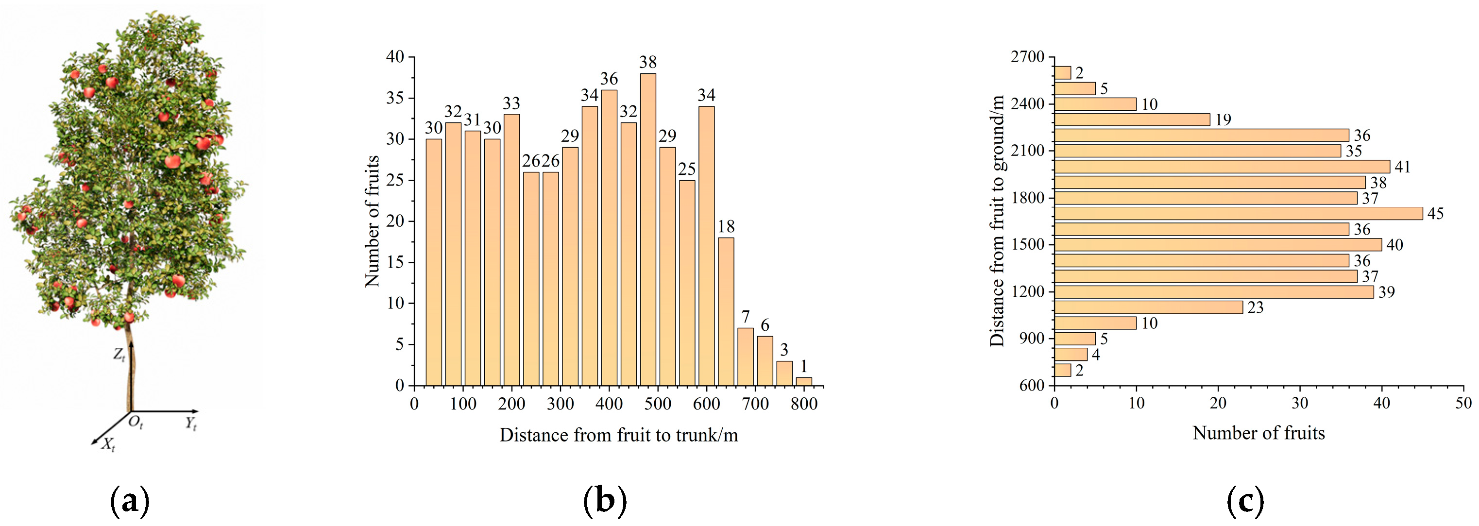
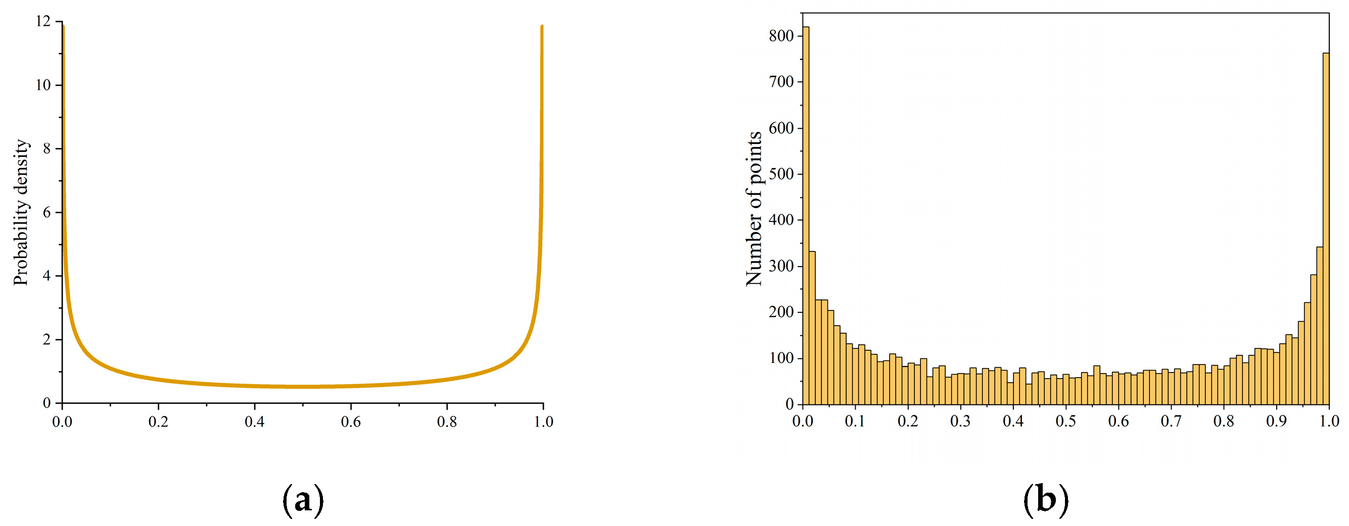
2.1.1. Fruit Distribution Characteristics and Single-Domain Picking Base Point Positioning

Currently, standardized apple orchards predominantly adopt the densely planted dwarf rootstock model [19], with the main tree shapes being spindle and espalier, for which the parameters at maturity are shown in Table 1. To determine the spatial distribution of the fruit, the origin of the coordinate system was established at the intersection of the tree trunk and the ground, forming the XtYtZt coordinate system (Figure 1a). In this system, the Xt-axis represents the row direction, the Yt-axis represents the intra-row spacing direction, and the Zt-axis is perpendicular to the ground.
To avoid edge effects during fruit coordinate measurements, ten non-peripheral apple trees were randomly selected within a standardized orchard. The corresponding spatial reference system of each fruit tree was established based on the fruit tree coordinate system XtYtZt. Prior to measurement, 10% of the samples were independently measured by two operators to calibrate tool errors, and vertical deviations were corrected using a plumb line. During measurement, the origin of the XtYtZt coordinate system was taken as the base point. A laser rangefinder and a digital goniometer were used to record the polar coordinate parameters of each apple. The collected data were then converted into Cartesian coordinates to obtain the fruit distribution data within the XtYtZt coordinate system. The distribution of the number of fruits along the Yt and Zt axes is shown in Figure 1b,c.
As shown in Figure 1, the fruits were primarily distributed at heights ranging from 700 mm to 2600 mm above the ground, with a horizontal distance from the main trunk ranging from 0 mm to 800 mm.
Based on the fruit distribution characteristics and canopy thickness, the harvesting domain for a single apple tree was simplified into a rectangular prism (1600 mm × 300 mm × 1900 mm). To achieve a compact device structure, the XtOtZt plane was used to divide the harvesting domain into two target harvesting areas, U1 and U2, as shown in Figure 2a. To reduce the number of positioning operations, a single positioning was used within each domain. Taking U1 as an example, the geometric center of its front surface was defined as point A0. The point was then translated along the positive direction of the Xt-axis by a distance of NA (300 mm) to point A1, which served as the harvesting reference point (XA1, YA1, ZA1).

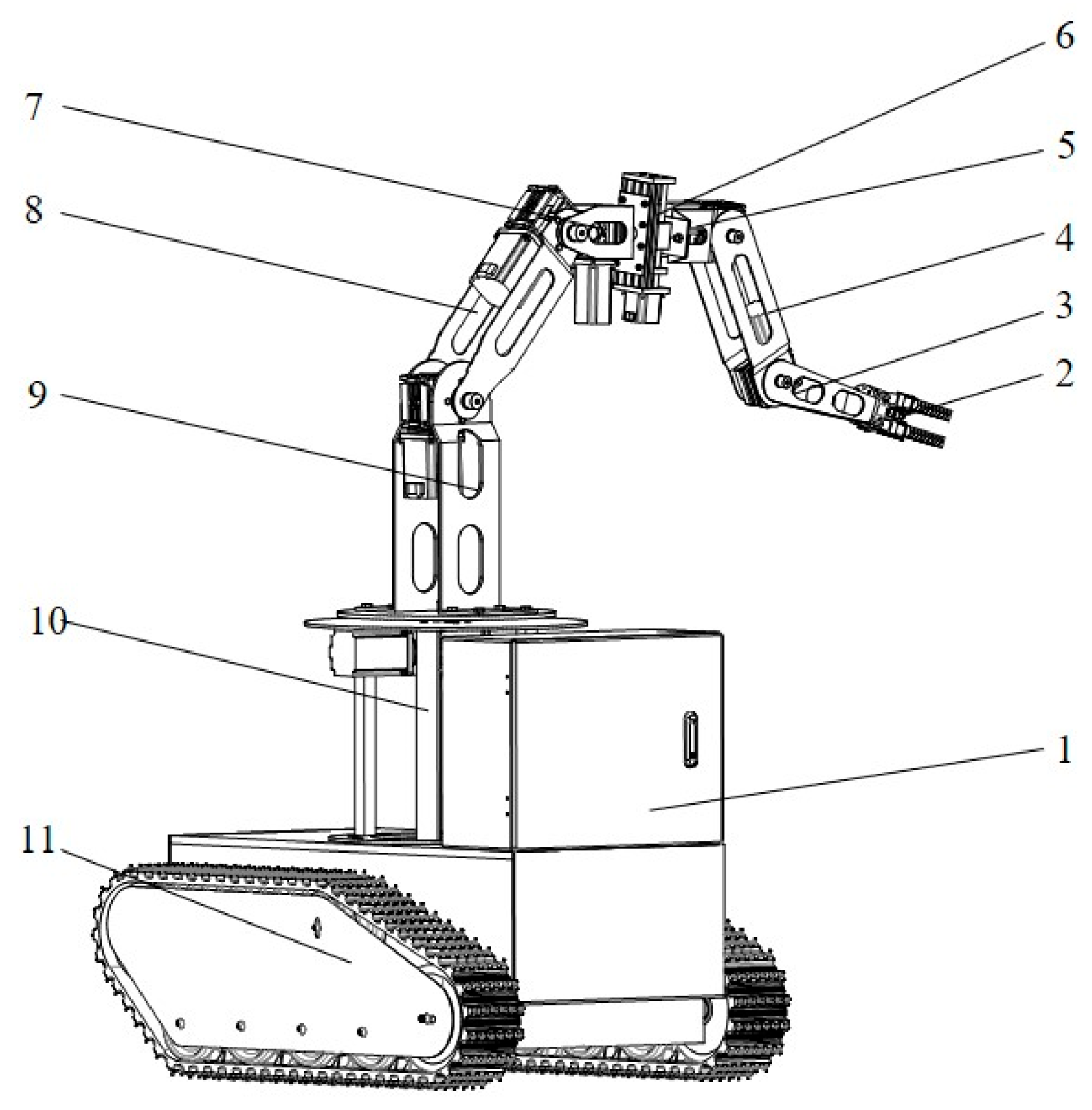
2.1.2. Machine Structure

The structure of the two-stage domain-segmented harvesting device for densely planted dwarf apple orchards is shown in Figure 3. It mainly consists of a mobile chassis, harvesting reference point positioning mechanism, fruit-picking agency, and control system. Based on the characteristics of domain-segmented harvesting and the one-positioning-multiple-picking operational mode, the focus was placed on the design of the harvesting reference point positioning mechanism and the fruit-picking mechanism. The harvesting reference point positioning mechanism is a 3R robotic arm structure, consisting of a base frame, supporting arm, elevating arm, and secondary rotation arm. The fruit-picking mechanism adopts an R-P-R-R structure, composed of primary rotation arm, translation arm, main fruit harvesting arm, auxiliary fruit gripping arm, and multi-functional gripper. The control system, implemented through MATLAB R2020a, Python 3.9.13, and a microcontroller, automates the harvesting operation. The positioning reference point is the center of the secondary rotation arm’s end, while the harvesting point is the center of the multi-functional gripper’s grip. The main technical parameters are shown in Table 2.

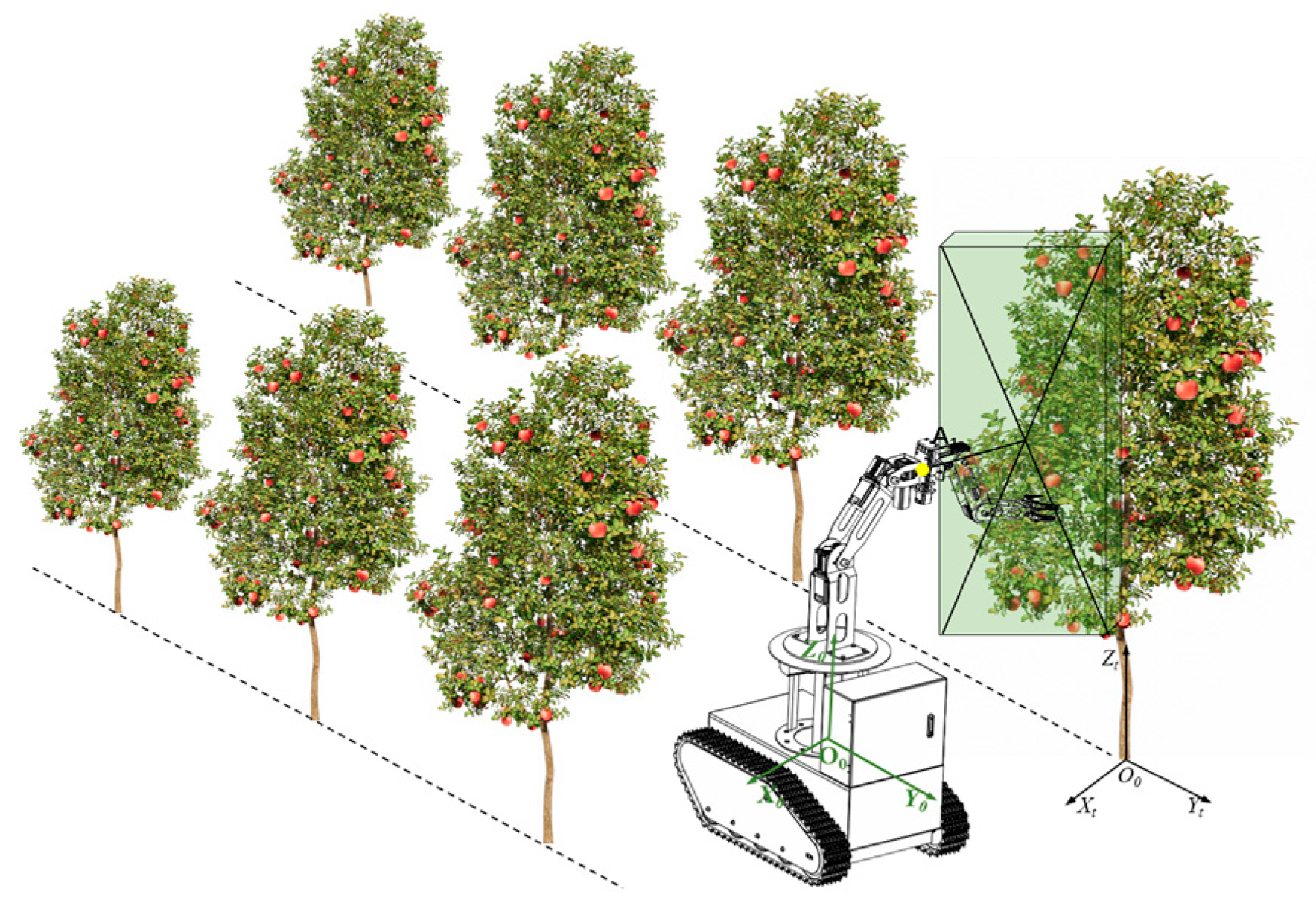
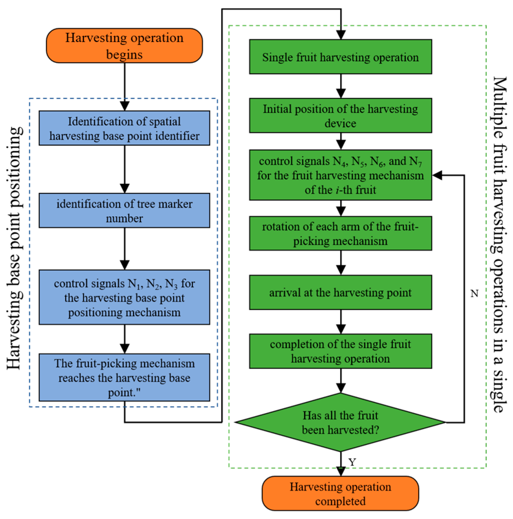
2.1.3. Working Principle

The two-stage domain-segmented harvesting device for densely planted dwarf apple orchards enables automated apple harvesting (Figure 4). During operation, the device is positioned between two rows of apple trees, aligning its column with one-quarter of the canopy width. A coordinate system, X0Y0Z0, is established with the center of the rotating. Based on the previously determined harvesting reference point, the inverse kinematics solution was used to calculate the rotation angles of the elevating arm and secondary rotation arm. The control system then drove the motors to rotate by the corresponding angles, ensuring that the positioning reference point reached the harvesting reference point, thereby achieving single-point position. MATLAB R2020a was used to convert the target fruit’s coordinates from the XtYtZt system to the X0Y0Z0 coordinate system. Based on the required harvesting posture, a stochastic point-geometric fusion method was employed to determine the joint variables of each arm in the fruit-picking mechanism. These joint variables were then input into the microcontroller using Python 3.9.13, which controlled the fruit-picking mechanism to perform sequential automated fruit harvesting.

2.2. Key Component Design

2.2.1. Harvesting Reference Point Positioning Mechanism

The primary function of this mechanism is to achieve reference point positioning for the fruit-picking mechanism, thereby reducing the overall positioning time during the harvesting process, simplifying the picking motions, and minimizing the structural dimensions. To meet these requirements, the harvesting positioning posture was determined, as shown in Figure 5a. During operation, the harvesting device moves along the middle of the tree rows. The supporting arm rotates to align the positioning mechanism plane perpendicular to the Yt-axis. Subsequently, the elevating arm and secondary rotation arm rotate sequentially by specific angles, ensuring that the axis of the secondary rotation arm passes through point A0 and remains parallel to the XtOtYt plane.
To describe the X0Y0Z0 coordinates of the positioning reference point, the XtYtZt coordinates from Section 2.1 were transformed using the special Euclidean group SE (3) [20].
S E 3 = R P 0 1 P 3 , R S O ( 3 )
where, P is a 3 × 1 matrix representing the relative position of the origin of the XtYtZt coordinate system with respect to the origin of the X0Y0Z0 coordinate system. R is a 3 × 3 matrix representing the relative orientation of the XtYtZt coordinate system with respect to the X0Y0Z0 coordinate.
System SO (3) denotes the rotation subgroup, which is defined as:
S O 3 = R 3 × 3 R T R = Ι , det R = 1
where, I is the identity matrix, and the determinant of R equals 1.
Therefore, in the X0Y0Z0 coordinate system, the coordinates of point A1 are (−650 mm, 0, 1200 mm).
Based on the apple tree morphology parameters (Table 1) and the fruit distribution characteristics, a uniform distribution design was adopted, ensuring that the height of the base frame is equal to the length of the supporting arm. According to the positioning posture, both the elevating arm angle θ2 and the secondary rotation arm angle θ3 are set to 45°. The top end of the supporting arm is positioned at one-quarter of the distance from the lower surface of the target harvesting region. Referring to Figure 5b, the lengths of each arm are calculated as follows:
l 0 = 1 2 Z A 1 4 h
l 1 = l 0
l 2 = Z A l 1 l 0 sin θ 2
l 3 = X A l 2 × cos θ 2
where, XA is the absolute value of the X-axis coordinate of the harvesting reference point, ZA is the absolute value of the Z-axis coordinate of the harvesting reference point, h is the height of the target harvesting region, l0 is the height of the support structure, l1 is the length of the base arm, l2 is the length of the elevating arm, l3 is the length of the secondary rotation arm, θ2 is the rotation angle of the elevating arm.
From the above calculations, it can be concluded that the design parameters are l0 = 370 mm, l1 = 370 mm, l2 = 650 mm, l3 = 200 mm.

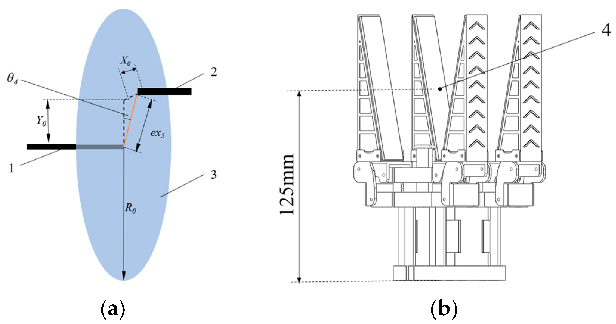
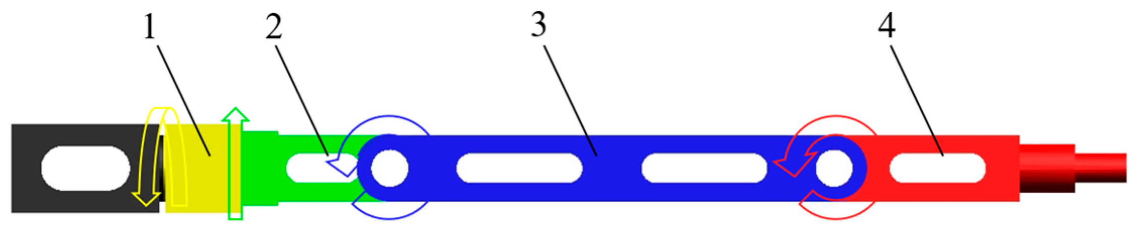
2.2.2. Fruit-Picking Mechanism

To enlarge the harvesting domain and adjust the harvesting posture, the primary rotation arm and the translation arm form a tilt-shift structure, as illustrated in Figure 6a. The end of the translating arm can reach any position within a circle of radius (R0 = 100 mm). To achieve stable grasping and lightweight design, a single-driven four-finger flexible gripper was chosen, with the harvesting reference point located 125 mm above the base, as shown in Figure 6b. Based on the target harvesting domain dimensions, its projection (Figure 7) approximates a rectangular region with a height (h = 1900 mm) and a width (l = 800 mm). According to the harvesting motion and fruit distribution characteristics, the joint range parameters are listed in Table 3.
From the positioning posture, it can be observed that the axis of the secondary rotation arm passes through point A1. To ensure that the harvesting domain of the fruit-picking mechanism encompasses the target harvesting domain, the harvesting limit position (the vertex of the projection plane) was determined based on its geometric features. The arm length design parameters were then specified as follows: ex5 = 100 mm, θ6 = 60°, and θ7 = 30°. The dimensional design is shown in Figure 7.
According to the structural design, the arm length of the primary rotation arm (l4) is set to 100 mm, while the arm length of the translation arm (l5) is set to 200 mm. The arm lengths of the main fruit harvesting arm (l6) and the auxiliary fruit gripping arm (l7) are determined as follows:
l 6 = N A + w l 5 l 4 cos θ 6
l 7 = L A l 6 × sin θ 6 e x 5 l 8
where w is the width of the target harvesting region, θ6 is the rotation angle of the main fruit harvesting arm, NA is the distance between the harvesting reference point A1 and the geometric intersection center A0, LA is the distance between the apex of the target harvesting region’s projection plane and its center, measuring 1150 mm.
Based on the calculation results, to ensure the complete coverage of the target harvesting region, the length of the main fruit harvesting arm (l6) is set to 600 mm, and the length of the auxiliary fruit gripping arm (l7) is set to 400 mm.

2.3. Forward Kinematics Model of Picking Device

Based on the aforementioned dimensional design and joint parameter ranges, a kinematic model has been constructed to describe the motion of the harvesting device and simulate the harvesting workspace [21]. The following assumptions have been made: the ground is considered rigid, all components are treated as rigid bodies, and the effects of joint clearance and friction are neglected. According to these assumptions, the supporting arm is defined as Link 1, the elevating arm as Link 2, the secondary rotation arm as Link 3, the primary rotation arm as Link 4, the translation arm as Link 5, the main fruit harvesting arm as Link 6, and the auxiliary fruit gripping arm as Link 7. The coordinate system origins are set at the circular center of the base frame bottom surface and the joint center of the secondary rotation arm. The Denavit–Hartenberg (D–H) method [22,23] has been applied to establish the link coordinate systems of the harvesting device, as illustrated in Figure 8. The corresponding parameters are presented in Table 4 and Table 5.
Based on the D–H parameter method, the 4 × 4 homogeneous transformation matrix T i 1 i T for the coordinate system {i} relative to the previous coordinate system {i − 1} was established. The transformation matrix is composed of the four parameter variables ai, αi, di, and θi, and is the product of four sub-transformation matrices.
T i 1 i = 1 0 0 0 0 1 0 0 0 0 1 d i 0 0 0 1 cos θ i sin θ i 0 0 sin θ i cos θ i 0 0 0 0 1 0 0 0 0 1 1 0 0 a i 0 1 0 0 0 0 1 0 0 0 0 1 1 0 0 0 0 cos α i sin α i 0 0 sin α i cos α i 0 0 0 0 1 = cos θ i sin θ i cos α i sin θ i sin α i a i cos θ i sin θ i cos θ i cos α i cos θ i sin α i a i sin θ i 0 sin α i cos α i d i 0 0 0 1
The forward kinematics models of the picking point positioning mechanism and the fruit picking mechanism were solved using the above formula, as follows:
T 0 4 = T 0 1 T 1 2 T 2 3 T 3 4 = c θ 3 σ 1 s θ 3 σ 2 0 c θ 3 σ 2 s θ 3 σ 1 l 3 c θ 3 σ 1 l 3 s θ 3 σ 2 l 2 c θ 1 s θ 2 + l 2 c θ 2 s θ 1 c θ 3 σ 2 + s θ 3 σ 1 0 c θ 3 σ 1 s θ 3 σ 2 l 3 c θ 3 σ 2 + l 3 s θ 3 σ 1 l 2 c θ 1 c θ 2 l 2 s θ 1 s θ 2 0 1 0 d 1 + l 1 0 0 0 1
T 0 7 = T 0 4 T 4 5 T 5 6 T 6 7 = s θ 4 s θ 6 c θ 7 + s θ 4 c θ 6 s θ 7 s θ 4 s θ 6 s θ 7 + s θ 4 c θ 6 c θ 7 c θ 4 l 7 s θ 4 s θ 6 c θ 7 + l 7 s θ 4 c θ 6 s θ 7 l 6 s θ 4 s θ 6 + e x 5 s θ 4 c θ 4 s θ 6 c θ 7 + c θ 4 c θ 6 s θ 7 c θ 4 s θ 6 c θ 7 + c θ 4 c θ 6 c θ 7 s θ 4 l 7 c θ 4 s θ 6 c θ 7 + l 7 c θ 4 c θ 6 s θ 7 + l 6 c θ 4 s θ 6 e x 5 c θ 4 c θ 6 s θ 7 c θ 6 s θ 7 c θ 6 s θ 7 s θ 6 c θ 7 0 l 4 + l 5 + l 6 c θ 6 + l 7 c θ 6 c θ 7 l 7 s θ 6 s θ 7 0 0 0 1
where, σ1 = cθ12-sθ12; σ2 = cθ12 + cθ21; sθi = sinθi; cθi = cosθi, i = 1, 2…

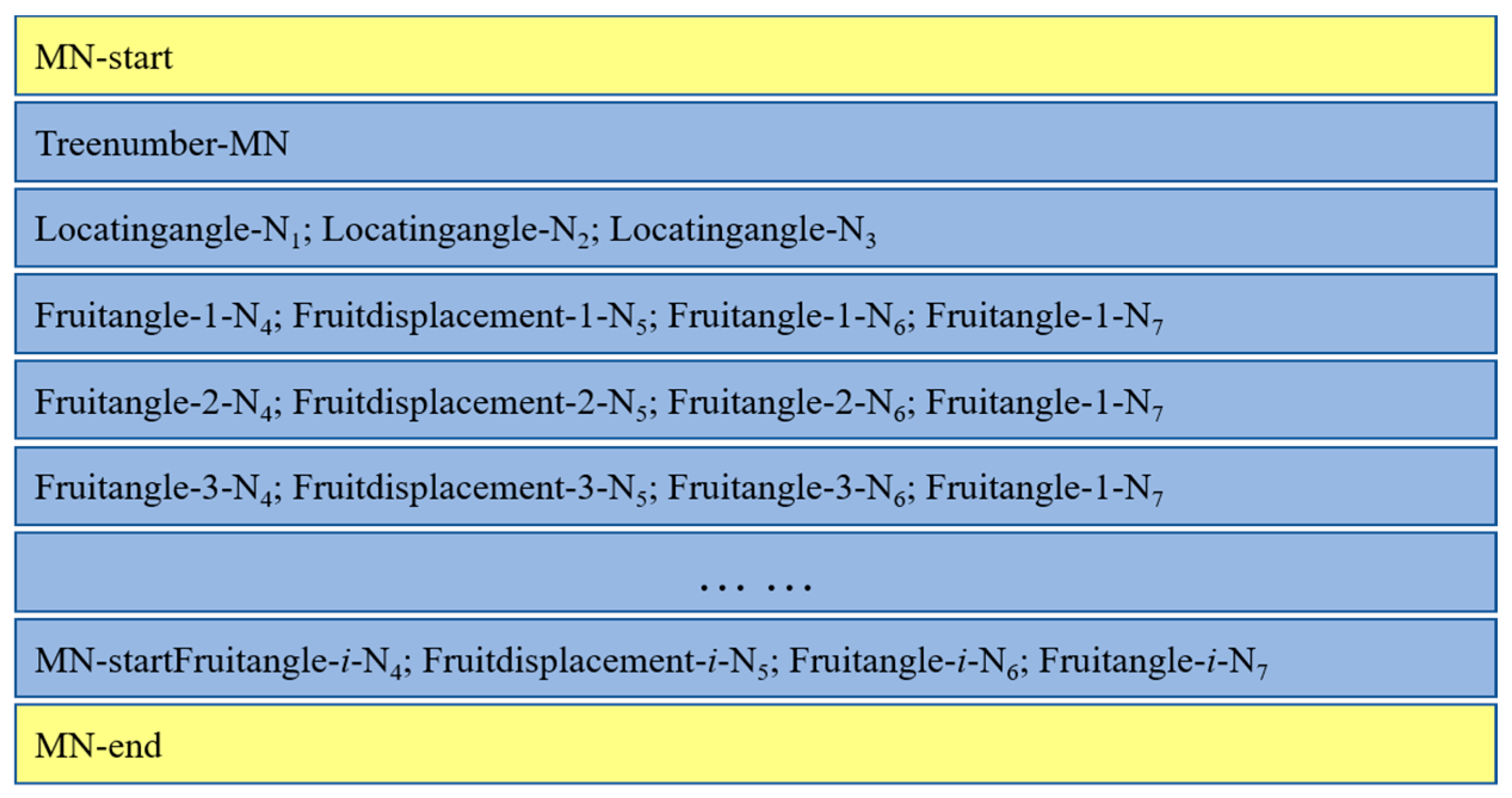
2.4. Control System Design

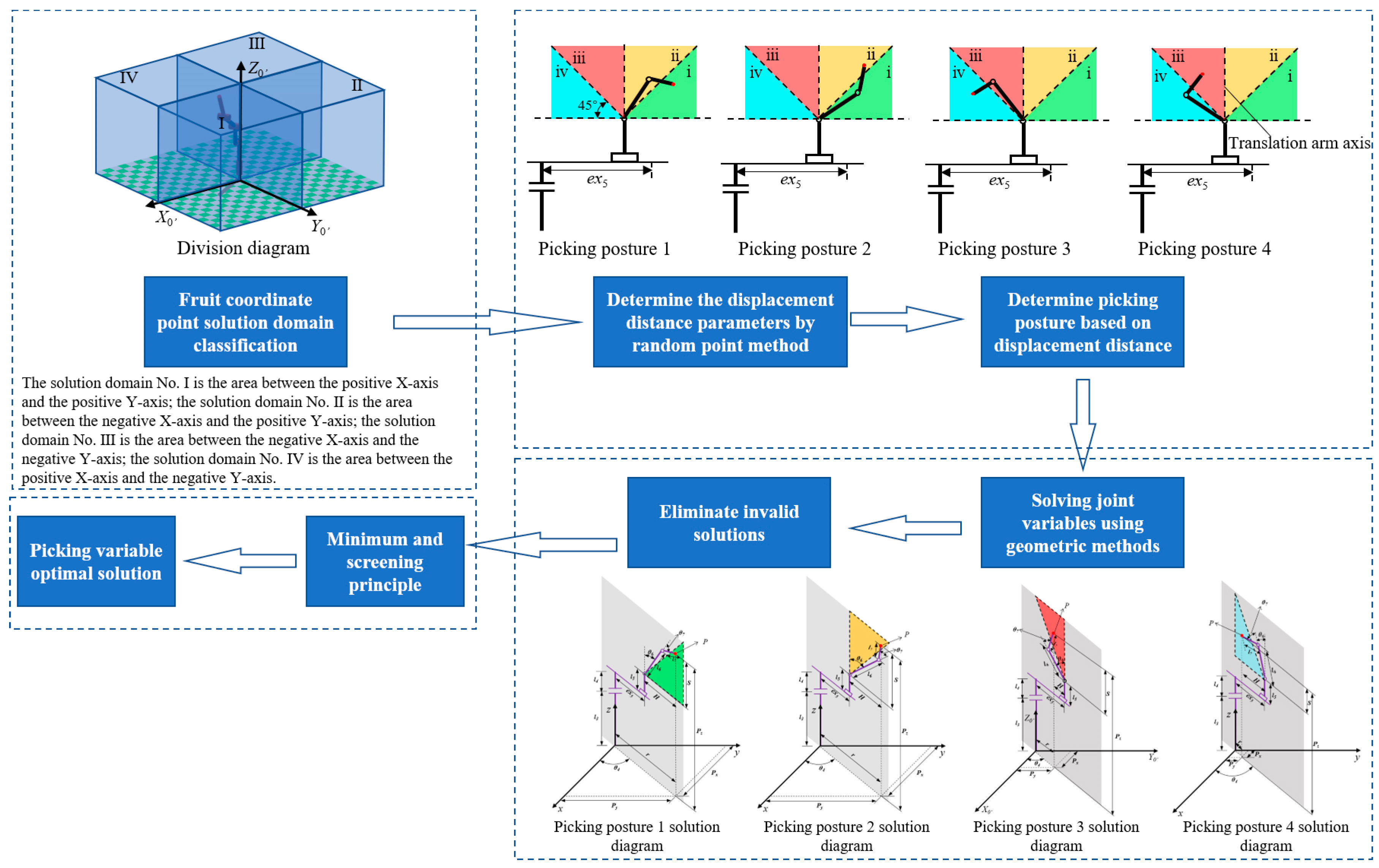
2.4.1. Inverse Kinematics Model Based on Random Point-Geometry Fusion Method

To establish the functional relationship between the picking point coordinates and joint variables, develop the control system, and achieve automated picking operations, inverse kinematics models for both the picking base point positioning mechanism and the fruit-picking mechanism have been formulated based on the structural characteristics and joint motion types of the picking device [24]. The models are presented as follows:
(1) Inverse Kinematics Model of the harvesting reference point positioning mechanism
Based on the coordinates of point A1 in Section 2.1 and Figure 9, the inverse kinematics model has been constructed using the geometric method. The corresponding solution diagram is shown in Figure 9.
As shown in Figure 9, the parameters of the inverse kinematics model have been calculated, including the rotation angles of the supporting arm (θ1), elevating arm (θ2), and secondary rotation arm (θ3), as well as the distance M, which are given as follows:
θ 1 = a r c tan X A 1 Y A 1
θ 2 = arctan X A 1 2 + Y A 1 2 l 3 Z A 1 l 0 l 1
θ 3 = π 2 θ 2
M = w + N A + l 3 + l 2 × cos θ 2
where, XA1 is the X-axis coordinate of the picking reference point A1, YA1 is the Y-axis coordinate of the picking reference point A1, ZA1 is the Z-axis coordinate of the picking reference point A1, and M is the distance between the origin and the main trunk of the fruit tree.
(2) Inverse Kinematics Model of the fruit-picking mechanism
Based on the structure of the fruit-picking mechanism and the characteristics of the picking process, a random point-geometric fusion inverse kinematics method has been proposed to reduce computation time and improve efficiency. The solution process is illustrated in Figure 10.
First, to quickly determine and compute the joint rotation angles, the solution domain has been partitioned based on the X0′Y0′Z0′ coordinate system (Figure 8b), as shown in Figure 10. According to the fruit coordinates (XP, YP, ZP), the corresponding solution domain classification is performed.
Next, based on the translation arm’s movement distance and the distribution of fruit coordinates within each solution domain, the workspace is divided into left and right sections using the translation arm axis as a reference. A 45° diagonal line is then used to further divide the workspace into four posture regions (ⅰ~ⅳ). Using the random point method, ten sets of displacement distance parameters are obtained for a single fruit coordinate. Each displacement parameter is sequentially evaluated to determine the corresponding picking posture. Based on the structural dimensions of the picking mechanism, the appropriate picking posture is identified, and the joint angles are subsequently computed using a geometric approach.
Taking the picking domain I as an example, the primary rotation arm (θ4) and the vertical distance (S) between the fruit coordinate point P and the end point of the translational arm are given as follows:
θ 4 = arctan X P Y P
S = Z P l 3 l 4 l 5
where, XP is the X-axis coordinate value of the fruit coordinate point, YP is Y-axis coordinate value of the fruit coordinate point, and ZP is Z-axis coordinate value of the fruit coordinate point.
The offset distance (H) between the fruit coordinate point P and the displacement arm is given by:
H = e x 5 ± X P 2 + Y P 2
Among them, picking postures 1 and 2 are represented by “+”, while picking postures 3 and 4 are represented by “−”.
Based on the above equations, the picking main arm angle θ6 is given by:
θ 6 = π arccos l 6 2 + l 7 2 S 2 H 2 2 × l 6 × l 7
For picking postures 1 and 3, the picking minor arm angle θ7 is given by:
θ 7 = π 2 arctan S H arccos l 7 2 l 6 2 S 2 H 2 2 × l 6 × l 7 × S 2 + H 2
For picking postures 2 and 4, the picking minor arm angle θ7 is given by:
θ 7 = arctan S H + arccos l 7 2 l 6 2 S 2 H 2 2 × l 6 × l 7 × S 2 + H 2
Then, based on the 10 sets of displacement parameters, the joint angles of each arm are individually solved. Invalid solutions are eliminated by setting parameters to zero, obtaining the inverse kinematic solution set for a single fruit coordinate. Finally, the minimum sum filtering principle is applied to evaluate the total sum of each solution set within the inverse kinematic solution set. The solution set with the smallest sum is selected as the optimal picking solution.

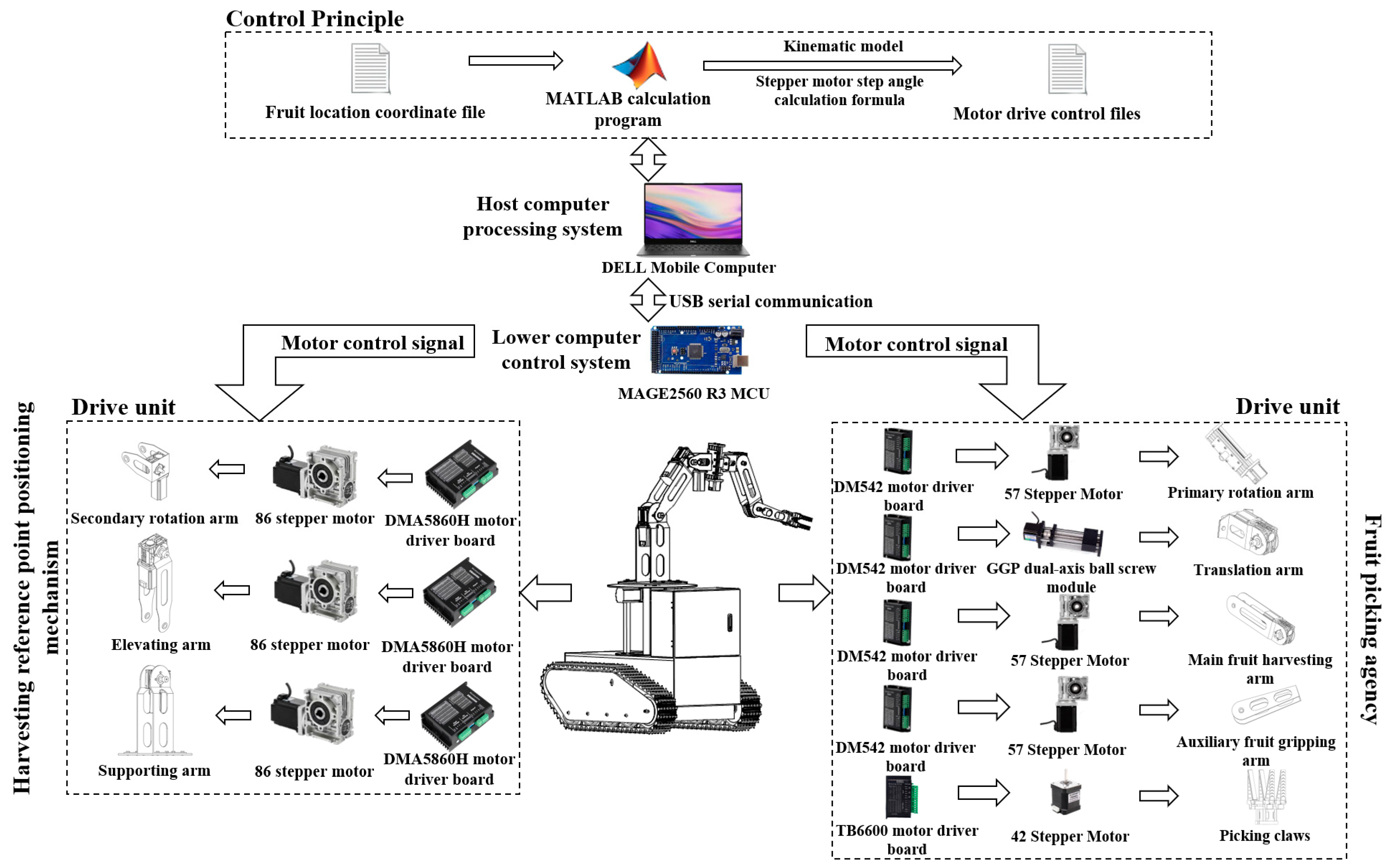
2.4.2. Control System

The control system consists of three main components: the host computer processing system, the lower computer control system, and the drive unit [25,26]. Its structural diagram is shown in Figure 11.
The DM542 stepper motor driver was selected as the driving unit. By adjusting its potentiometer, the input current and microstepping settings were configured to achieve precise control of the joint angles (Figure 12). The relationship between the joint angle and the number of pulses required by the motor is as follows:
N p i l s e = N S × N r × M r × G × θ l o a d 360 °
where, Ns is the number of electromagnetic phases of the stator, Nr is the number of magnetic poles of the rotor. Mr is the microstep resolution, θload is the target joint rotation angle, and G is the Gear reduction ratio.
The communication between the Arduino MEGA 2560 main control development board and the motors adopts an identifier-based control method. The format of the drive control file is shown in Figure 13. Based on the inverse kinematics model, the spatial position dataset of the fruits is converted into a drive control file using MATLAB R2020a. This file is then transmitted to the main control board via serial communication commands written in Python 3.9.13. According to the identifiers and Equation (22), the parameter control signals for the corresponding joints are sequentially computed and sent to the respective motor drivers. Each joint is thereby controlled to move to the corresponding fruit-picking position.
The specific process of the automatic fruit-picking mode (Figure 14) is as follows: First, the upper computer reads the target fruit spatial position data set and, using the special Euclidean group, transforms it into the X0Y0Z0 coordinate system through MATLAB R2020a. The joint angle set is then solved using the random point-geometry fusion method. Next, based on the motor driving principles, the pulse count for each joint is calculated, and an inverse kinematics parameter instruction set with direction identifiers is generated. Then, the lower computer (Arduino MEGA2560 R3 microcontroller Shenzhen Yuantaifeng Electronics Co., LTD, Shenzhen, China ) stores the instruction sequence in a buffer and uses a trapezoidal acceleration/deceleration algorithm to allocate the pulse frequency for each axis, thereby achieving smooth joint motion control. Finally, the drive unit receives the control instructions, performs the motor’s directional rotation to calculate the angle, and reaches the target fruit position.

2.5. Picking Device Performance and Simulation Test

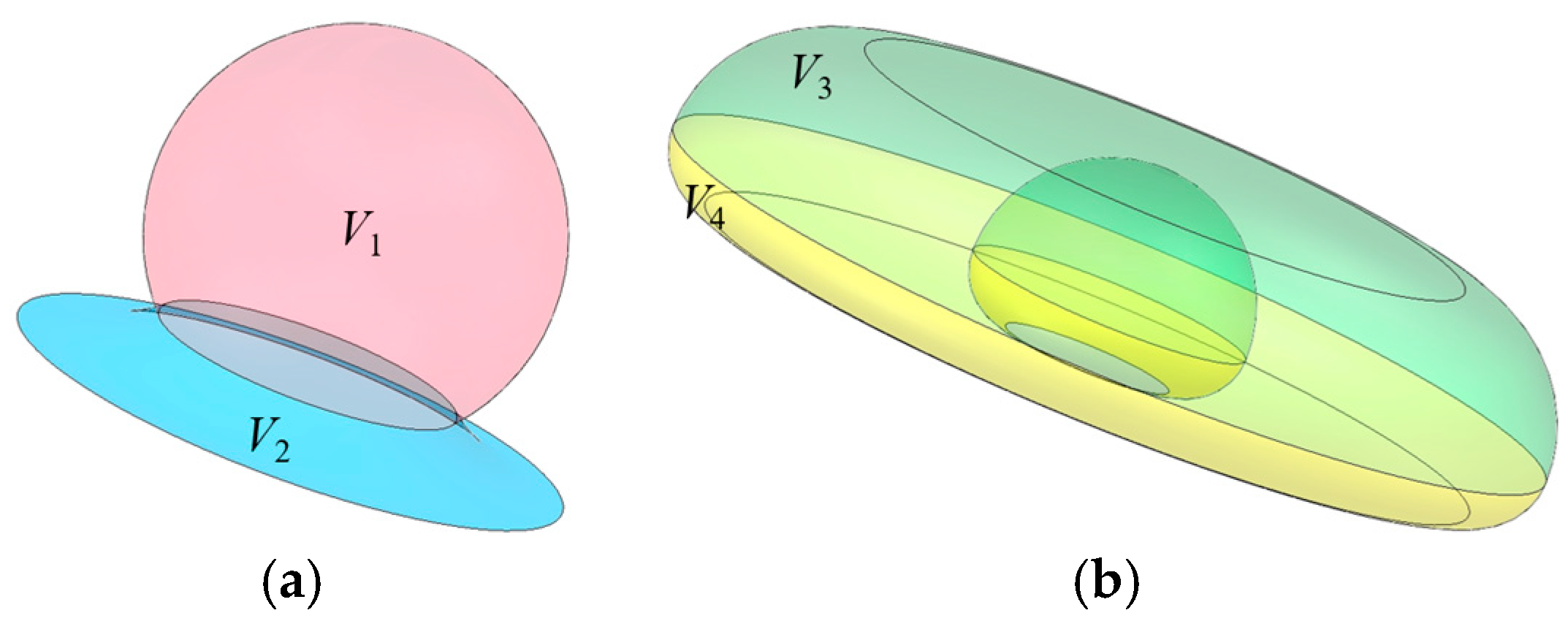
2.5.1. Tilt-Shift Structure Enhances Range Performance

To calculate the enlargement effect of the tilt-shift structure on the picking domain, based on the coordinate system O6X6Y6Z6 (Figure 8b), the fruit-picking mechanism was projected onto the X6O6Y6 plane. The mechanism was translated 100 mm from the initial position (3R structure) to the displacement limit position. In the initial position, the projected picking domain area was S0, while the enlarged picking domain areas were S1, S2, S3, and S4 (Figure 15). The picking domain volume was then obtained by rotating the picking mechanism’s projection 360° around the X6 axis.
The working space of the harvesting device is influenced by factors such as the type of joint motion, joint range of motion, and arm length [27,28]. A 3D simulation model of the harvesting mechanism was established using the MATLAB Robotics Toolbox to simulate the harvesting domain. To obtain the boundary range of the harvesting domain, the number of simulations of the boundary points was increased. An improved Monte Carlo method based on a mixed Beta symmetric distribution was proposed. Based on the structural parameters of the harvesting mechanism in Table 2 and its forward kinematics model, harvesting domain simulation experiments were conducted to verify whether the harvesting requirements could be met. The mixed Beta distribution density function (Figure 16) is as follows:
f x , α , β = μ 1 × x α 1 1 1 x β 1 1 0 1 u α 2 1 1 u β 1 1 d u + μ 2 x α 2 1 1 x β 2 1 0 1 u α 2 1 1 u β 2 1 d u
where, the values of α1, β1, α2, β2, μ1 and μ2 are taken as 0.5, 2, 2, 0.5, 0.5, and 0.5, respectively.

2.5.2. Driving Force Distance Simulation Test

The three-dimensional parametric model of the harvesting mechanism, constructed in SolidWorks 2021, was imported into ADAMS 2020 software. The spatial position and angle were adjusted, and various joint motion pairs were added [29,30]. By setting motion functions to drive the harvesting device, the dynamic model of the harvesting device was established, as shown in Figure 17.
Based on the simplified model of the harvesting device, the kinematic simulation parameters were set. Given that the average weight of a single fruit is 250 g, the force f acting on the end point of the harvesting forearm was set to 2.5 N, with a direction aligned with gravity. The movement was defined to follow the motion of the linkage. The gravitational acceleration g was set to 9.8 m/s². The structural parameters were defined as follows: the length of primary rotation arm l4 was 0.1 m with a mass m4 of 0.812 kg; the length of the translation arm l5 was 0.2 m with a mass m5 of 1.0 kg; the length of the main fruit harvesting arm l6 was 0.6 m with a mass m6 of 2.188 kg; and the length of the auxiliary fruit gripping arm l7 was 0.4 m with a mass m7 of 1.713 kg. The simulation was conducted for a duration of 24 s, using the center points of each joint as reference markers.

2.6. Prototype Experiment

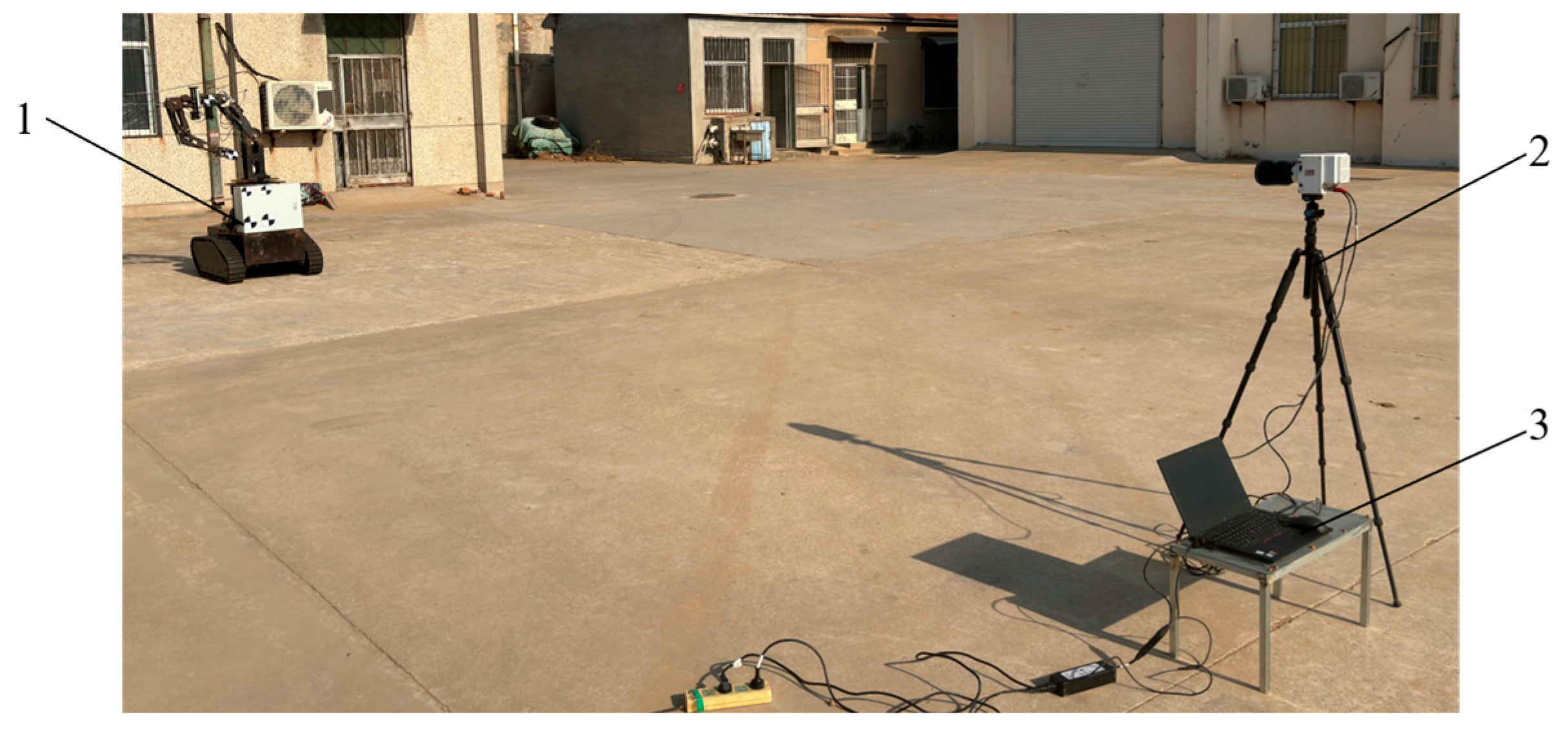
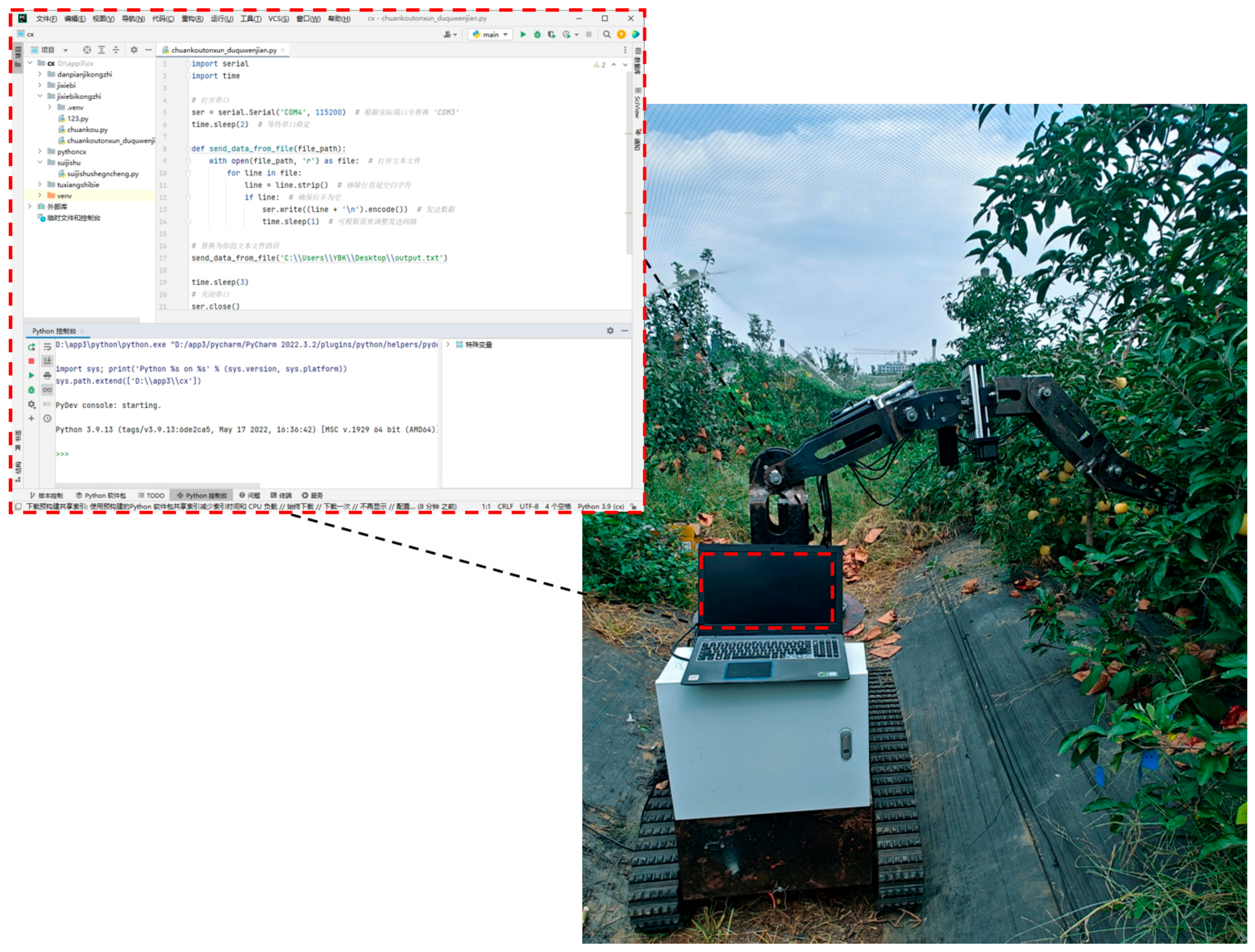
2.6.1. Experimental Instruments

Based on the developed harvesting device, the primary experimental instruments included a Lenovo ThinkBook mobile computer, a VEO410L high-speed camera (Beijing York Science & Technology Co., Ltd., Beijing, China), a DL1903 inclinometer (accuracy: 0.05°, Dongguan Chaoguan Electronic Equipment Co., Ltd., Dongguan, China), an HG-C1100 laser displacement sensor (accuracy: 0.01 mm, Panasonic Corporation, Kadoma, Japan), a vernier caliper (Delixi Electric Co., Ltd., Yueqing, China), a KD-491 digital thermometer (accuracy: 0.1 °C), a measuring tape, and a stopwatch.

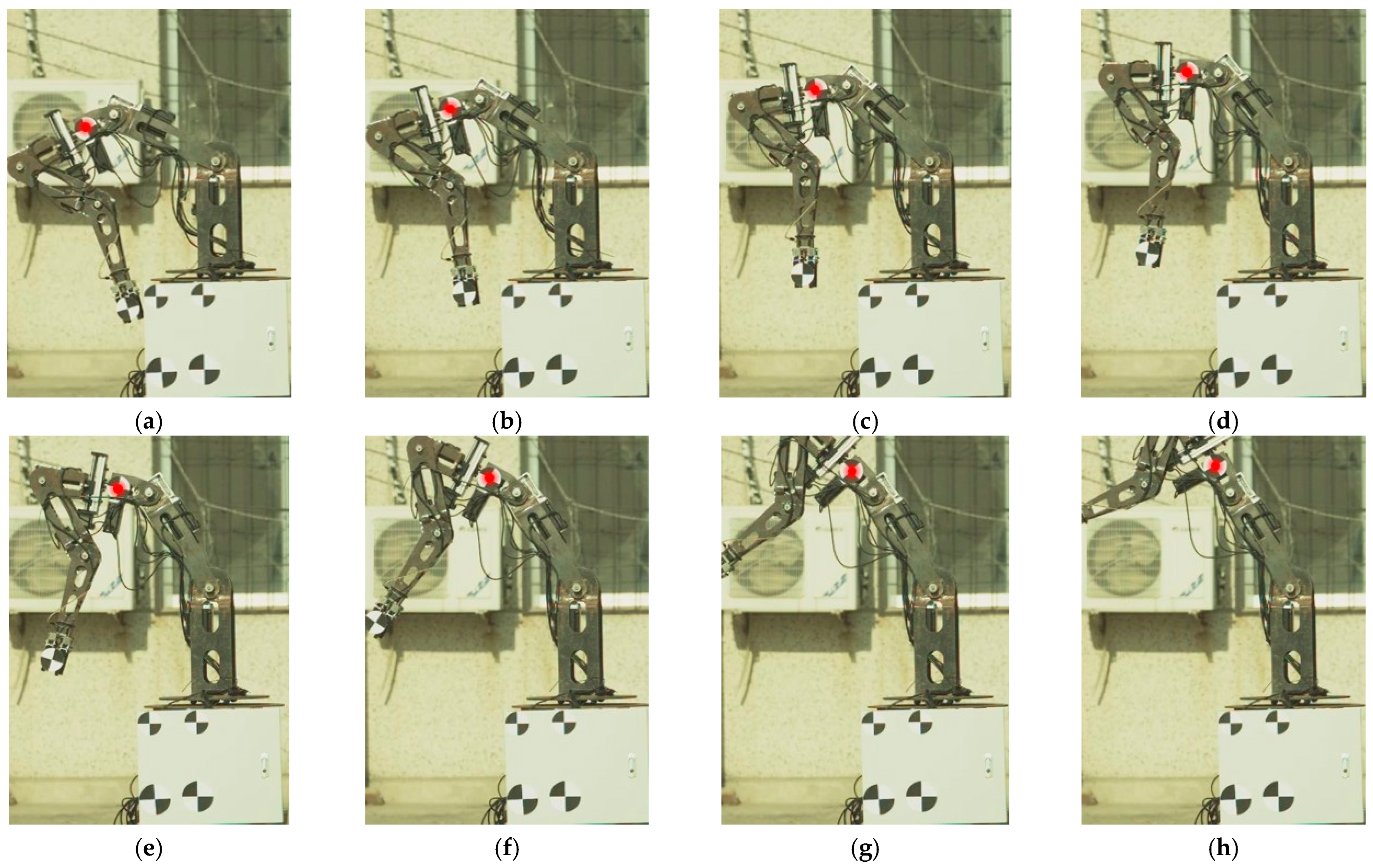
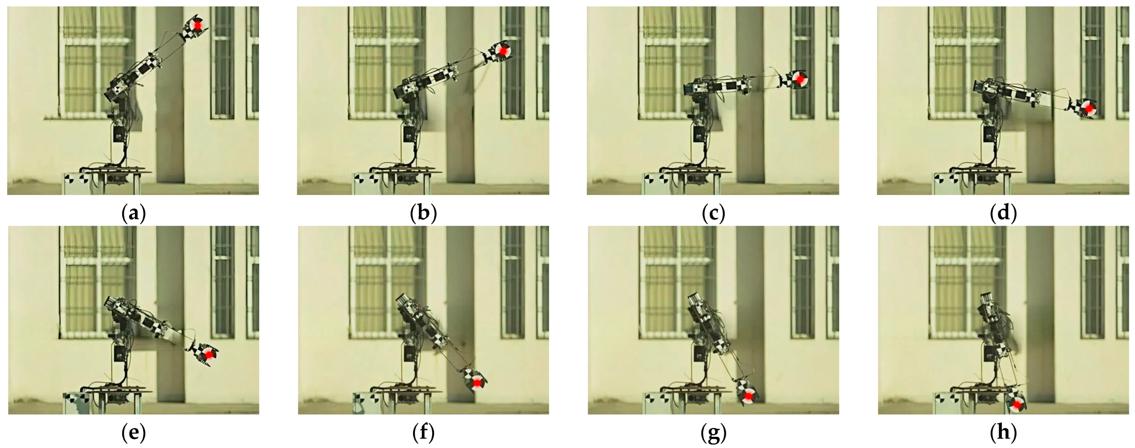
2.6.2. Positioning and Fruit-Picking Reference Point Tracking Experiment

According to the Agricultural Machinery Production Test Methods (GB/T 5667-2008) [31], a position tracking experiment was conducted on the harvesting device to evaluate the accuracy of its kinematic model by tracking the positioning and fruit-picking reference points. To minimize interference from orchard terrain and environmental complexities, and to ensure that the high-speed camera accurately captured the complete motion of the reference points, the experiment was conducted on an open, hard-surfaced area at the Agronomy Experimental Station of Shandong Agricultural University. The high-speed camera was configured with a resolution of 860 × 600, a sampling frequency of 2000 fps, and an exposure time of 190 μs. The tracking experiment site is shown in Figure 18, and the experiment was conducted in September 2024.

2.6.3. Harvesting Experiment

In October 2024, a harvesting experiment was conducted in the orchard at the Horticultural Experiment Base of Shandong Agricultural University. The experimental site is shown in Figure 19.
According to the standard for dwarf rootstock high-density planting, five mature apple trees were selected as the experimental subjects, with a total of 10 target harvesting areas. For each trial, only one side of the tree crown was harvested. The row spacing was 2 × 3 m, with an average tree height of 3.1 m and an average crown diameter of 1.6 m. The environmental temperature during the trial was 27.3 °C, and the terrain of the orchard was relatively flat. Prior to the harvest, the number of apples in the target harvesting areas, denoted as Ntraget, was counted. The number of successfully harvested apples, Nsucceed, during the harvesting process was recorded. The completion of all fruit harvesting within a single domain was considered as one trial. A total of 10 trials were conducted, and the harvesting time for each trial was recorded. The evaluation criteria for the harvesting device’s performance were based on the harvesting time and the harvesting success rate.

3. Results and Discussion

3.1. Simulation of Harvesting Domain Analysis

3.1.1. Analysis of Harvesting Domain Expansion Effect

As shown in Figure 20, the initial harvesting domain volume V0 is generated by the rotation of S0. The expanded harvesting domain volume V consists of V1, V2, V3, and V4, which are generated by the rotations of S1, S2, S3, and S4, respectively.
The expanded harvesting domain volume V is given by:
V = V 1 + V 2 + V 3 + V 4 = π 2 l 7 2 r 0 r 0 2 x 2 2 d x + π l 7 2 l 7 2 l 6 r 1 2 d x + π 0 l 6 + l 7 r 2 + e x 5 2 r 2 2 d x + π l 7 0 r 1 + e x 5 + l 6 2 r 1 + l 6 2 d x
where, r 0 2 = l 6 2 + l 7 2 2 l 6 l 7 , r 1 = l 7 2 x 2 , r 2 = l 6 + l 7 2 x 2
The initial harvesting domain volume V0 is given by:
V 0 = π 0 l 6 + l 7 r 2 + e x 5 2 d x + π l 7 0 r 1 + e x 5 + l 6 2 d x V
The calculated harvesting expansion volume V is 1.165 m3, while the initial harvesting domain volume V0 is 2.747 m3. The harvesting expansion rate β is used as an evaluation metric for the domain expansion effect of the shifting-axis structure.
β = V V 0 × 100 %
The calculation results show that the harvesting expansion rate β is 42.40%, indicating a significant domain expansion effect of the shifting-axis structure. This finding provides a design approach for expanding and optimizing the operational range of mechanized harvesting devices.

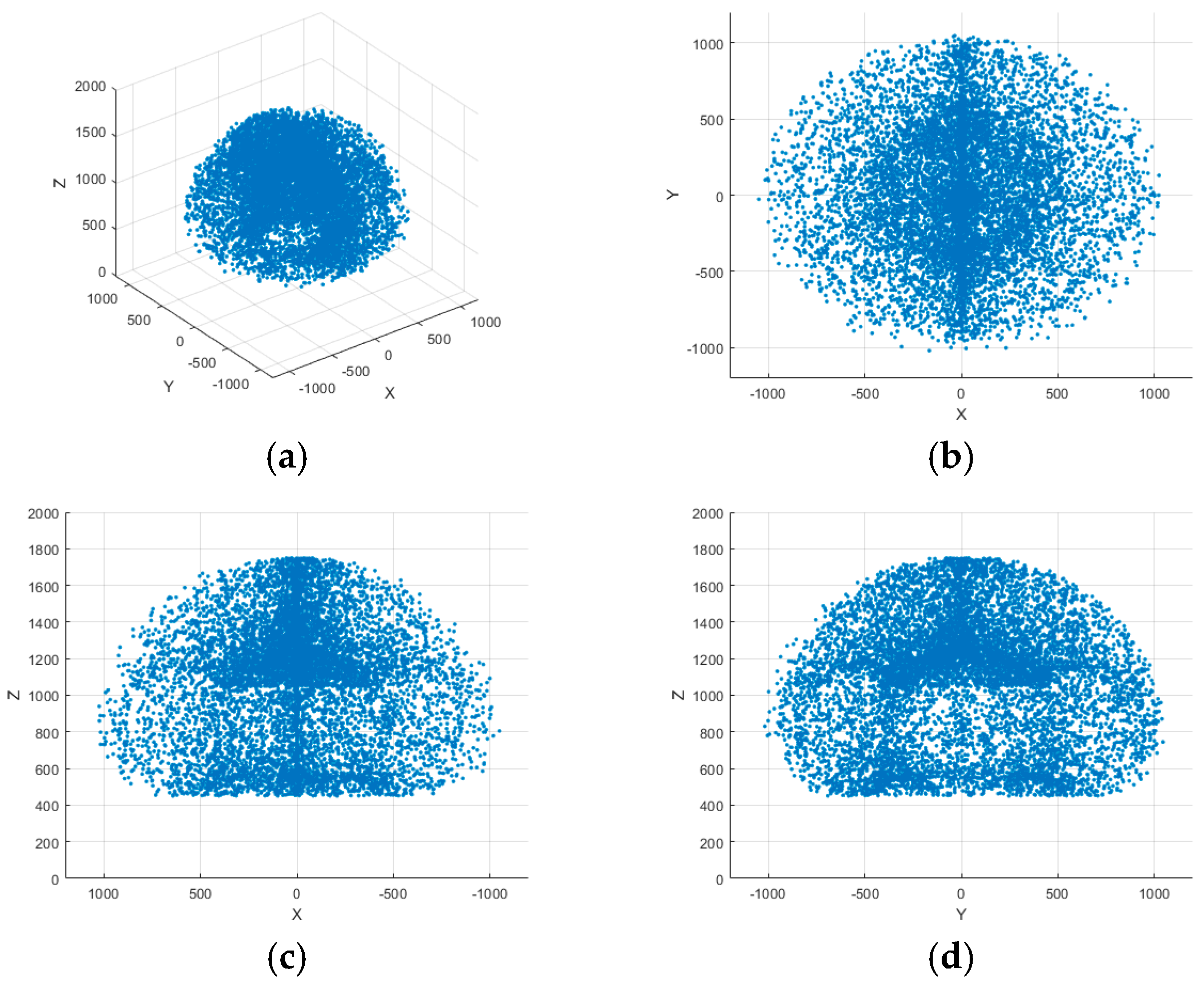
3.1.2. Simulation Analysis of the Harvesting Domain

Based on the aforementioned forward kinematics model and arm length parameters, an improved Monte Carlo method was used to generate 10⁴ sampling points within the joint angle range, obtaining the simulated domain of the fruit-picking reference points, as shown in Figure 21. The experiment was conducted ten times using the same method, and the average values of the results were taken. The maximum boundary distances of the fruit-picking reference points along the X, Y, and Z axes were 2146 mm, 2169 mm, and 2165 mm, respectively. Given that the chassis height of the harvesting device was 500 mm and the support frame height was 400 mm, the maximum reachable position of the picking claw was 2700 mm.
Based on Table 1, which presents the tree structure parameters and fruit distribution characteristics in densely planted dwarf apple orchards, the harvesting domain was analyzed. Apples generally grow along the main trunk at heights ranging from 0.7 to 2.6 m. The design of the shift-axis structure enables the harvesting claw’s operational space to form an ellipsoidal shape, effectively covering the target harvesting region and ensuring successful fruit picking from both upper and lower sections. The typical row spacing for apple cultivation is 2–3 m, allowing the harvesting device to cover a single planting row. In scenarios with larger row spacing, harvesting operations can be performed by adjusting the device’s movement path. Therefore, the operational range of the harvesting device meets the spatial requirements for effective fruit picking in agricultural environments.

3.2. Simulation Experiment Analysis

Joint Driving Force Simulation Analysis

The joint driving torque of the harvesting device is a critical parameter for system design, serving as the primary basis for motor selection and operational performance evaluation. Based on the single-fruit harvesting operation mode, a simulation experiment was conducted to analyze the torque of each joint in the picking mechanism. As is shown in Figure 22, the simulation results indicate that the driving force and torque of each arm exhibit periodic variations. At the simulation time of 12 s, corresponding to the beginning and end of a cycle, the driving torque reaches its peak due to the serial structure of the mechanism. The maximum driving torques for each joint are 36,937 N·mm, 31,562 N·mm, 22,439 N·mm, and 4371 N·mm, respectively, with torque differences of 36,626.17 N·mm, 28,585.94 N·mm, 9907.12 N·mm, and 2690.72 N·mm. The first rotational arm joint exhibits the highest driving torque and torque difference, making it a critical point for joint design. These findings provide a theoretical foundation for motor selection in the serial harvesting device structure.

3.3. Prototype Experiment Results and Analysis

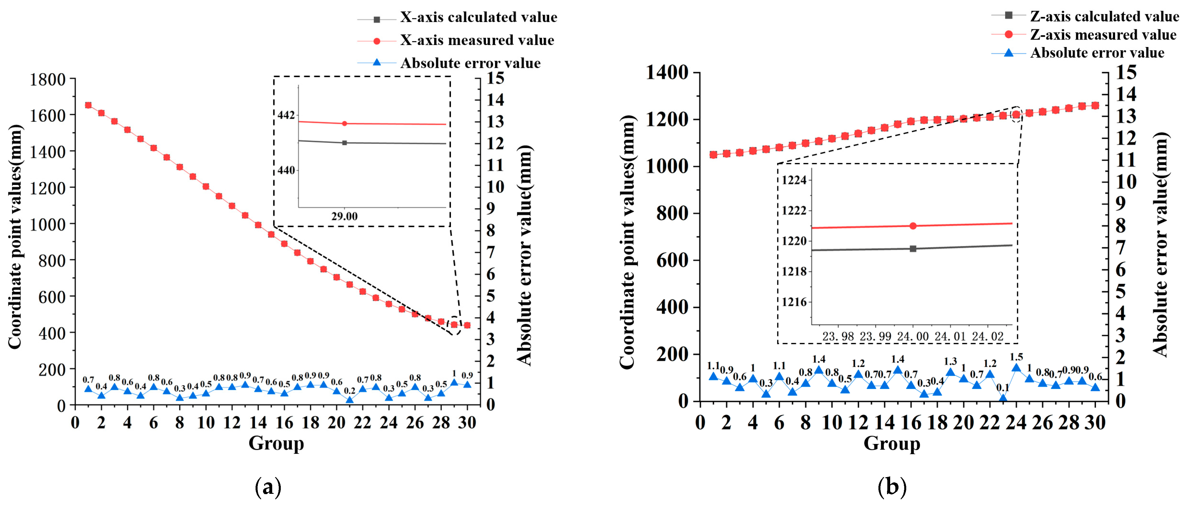
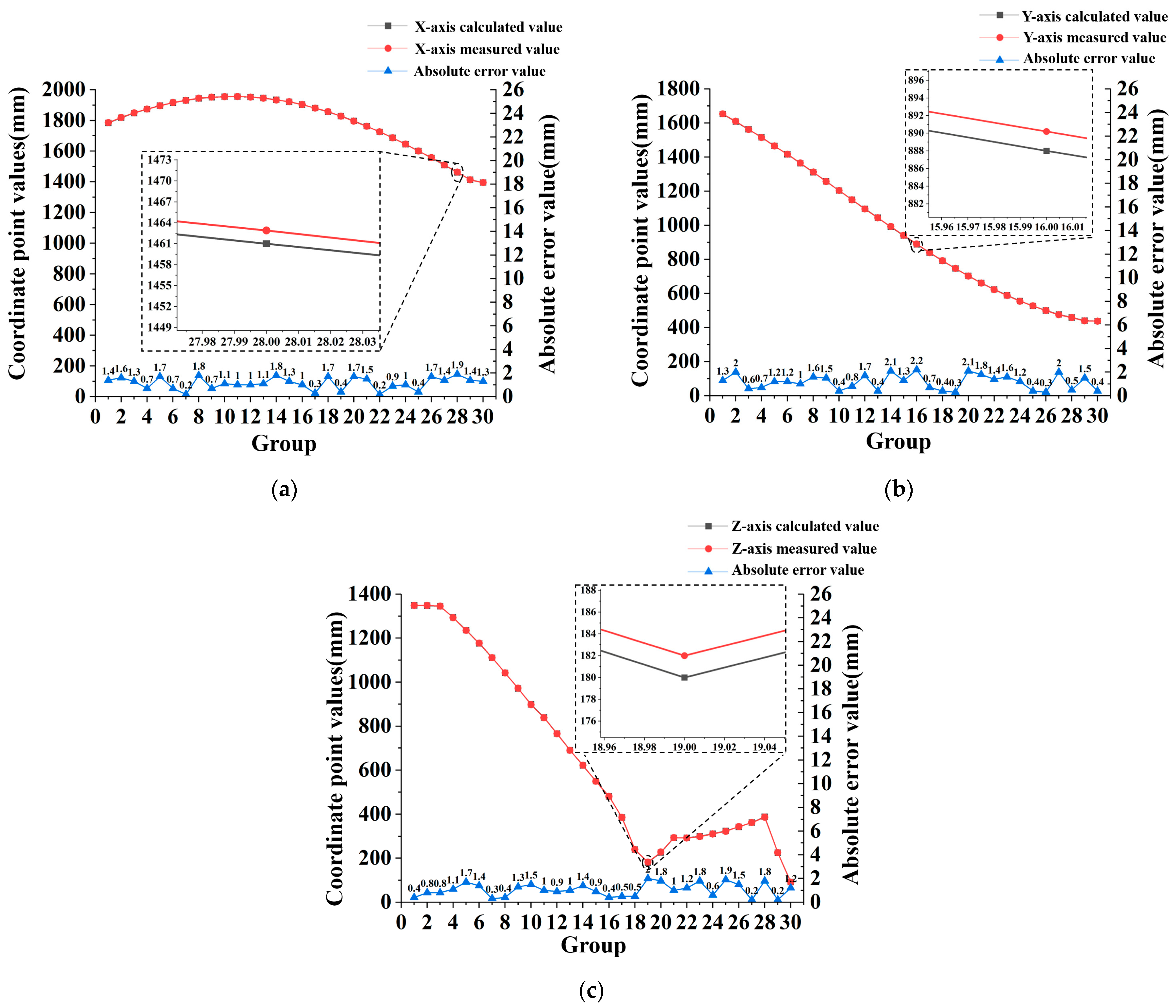
3.3.1. Position Analysis of the Localization and Fruit-Picking Reference Points

To verify the accuracy of the kinematic model, a reference point position tracking test was conducted based on the coordinate system O0X0Y0Z0. The joint angles θ1, θ2, and θ3 were measured using an inclinometer. A high-speed camera was used to track and locate the reference points, capturing a total of 41,581 frames. Images were extracted at intervals of 1433 frames, resulting in 30 images in total, with some of these images shown in Figure 23.
To verify the accuracy of the kinematic model, a reference point position tracking experiment was conducted based on the coordinate system O0′X0′Y0′Z0′. The joint angles θ4, θ6, and θ7, along with the displacement distance ex5, were measured using an inclinometer and a laser displacement sensor, respectively. A total of 31,645 frames were captured during the process, and images were extracted at intervals of 1091 frames, resulting in 30 images. Some of these images are shown in Figure 24.
Using TEMA 2019 software (Image Systems AB, Sweden), a dynamic coordinate system for the test images was established, with a scale for the coordinates divided and reference points annotated on the images. The position data of the reference points from the images were exported to validate the kinematic models of both the picking base point positioning mechanism and the fruit picking mechanism.
Based on the prototype’s positioning posture, the positioning mechanism’s plane was coplanar with the X0O0Z0 plane, so there was no change in the reference point along the Y-axis. Using the kinematic model, a comparison was made between the measured and calculated values of the reference point on the X and Z axes, as shown in Figure 25.
The experimental results show that the maximum errors in the X and Z axis coordinates are 1.0 mm and 1.5 mm, respectively, indicating that the kinematic model of the target picking point localization mechanism is correct.
Based on the tracking images captured by the high-speed camera, the frame images of the tracking points were extracted to obtain the coordinate values of the picking reference point in the X, Y, and Z directions. By combining the measured joint variables θ4, ex5, θ6, and θ7 from the inclinometer and displacement sensor, the experimental parameters and measurement data were substituted into the kinematic model to obtain the calculated values of the picking reference point in the X, Y, and Z directions. The comparison between the measured and calculated values is shown in Figure 26.
As shown in Figure 26, the maximum error values in the X, Y, and Z directions for the corresponding frame images were 1.9 mm, 2.2 mm, and 2.0 mm, respectively. This indicates that the kinematic model of the fruit picking mechanism was correct.

3.3.2. Fruit Picking Experiment Results Analysis

Based on the picking test results, the automatic picking success rate η within a single domain is calculated using the following formula:
η = N s u c c e e d N t r a g e t × 100 %
where Ntraget is the number of target fruits in the domain, Nsucceed is the number of successfully picked fruits.
This picking test involved 10 target picking areas, and 387 fruits were successfully picked. The results of the picking test were statistically analyzed, and the test results of the 10 target picking areas are shown in Table 6.
As shown in Table 6, due to the differences in the number of fruits and their distribution characteristics within the picking domain, the single-domain picking time varied for each group. Therefore, the average value of the 10 sets of single-domain picking time data was calculated. The average fruit-picking success rate reached 76.53%, with a standard deviation of 1.572 and a coefficient of variation of 2.06%. The low standard deviation indicates minor fluctuations in performance, while the low coefficient of variation further confirms strong operational stability, suggesting that the device demonstrates high reliability. The average time for picking a single fruit was 7.24 s, which improves 4.6% over the existing picking devices [16]. Its standard deviation was 0.1385, indicating minimal variation between individual picking times. The coefficient of variation was 1.91%, which is significantly below the 5% threshold commonly used in statistical analyses to determine operational stability. These results suggest that the proposed harvesting device can complete fruit-picking tasks with both high stability and efficiency. The primary cause of picking failure was identified as occlusion by branches, which led to the picking claws inadvertently grasping both the fruit and surrounding branches, thereby making it difficult to complete the harvesting process. Nonetheless, the results of the experiment meet the design requirements for apple harvesting.

4. Conclusions and Future Work

This paper, based on the dwarf rootstock dense planting mode for apple orchards, statistically analyzed fruit distribution characteristics to define the target harvesting areas. A two-stage domain partitioned apple harvesting device was designed. The forward kinematic model was established using the Denavit–Hartenberg (D–H) parameter method, and an improved Monte Carlo method based on a mixed Beta distribution was employed to obtain the simulated domain of the fruit picking reference point. The domain expansion effect of the tilt-shift structure was designed and quantified. Numerical simulations showed that the maximum distances along the X, Y, and Z axes were 2146 mm, 2169 mm, and 2165 mm, respectively. The tilt-shift structure increased the harvesting domain volume by 42.40%, raising the harvesting domain volume to 3.912 m3. To reduce computation time and improve efficiency, a random point-geometric fusion inverse kinematics method was proposed to solve the corresponding joint variables. The inverse kinematic models for the harvesting reference point positioning mechanism and the fruit picking mechanism were constructed. ADAMS simulation tests were conducted for joint motor design, and an automatic fruit picking control system was established. The positioning tracking tests showed that the maximum absolute errors for the positioning and fruit picking reference points were 1.5 mm and 2.2 mm, respectively, confirming the accuracy of the kinematic model. Orchard harvesting tests revealed that the device achieved a 76.53% success rate, with an average domain picking time of 280.25 s and an average fruit picking time of 7.24 s per fruit, an improvement of 4.6%. These results met the orchard’s harvesting requirements and provided design insights for expanding the operational range of apple harvesting devices.
According to the field test results, the primary cause of failure was the obstruction of branches, which hindered accurate positioning of the picking claws, resulting in misgrabbing of branches and unstable or incorrect fruit picking, preventing the separation of fruit from branches. To address these issues, future research will focus on two main aspects: (1) integrating agronomy with agricultural equipment, through manual intervention to manage and optimize branch arrangement and spacing, reducing the obstruction rate and making it more suitable for mechanized harvesting operations, and (2) enhancing equipment adaptability by combining algorithms and sensors to implement multi-angle and multi-posture target point approaching strategies, integrating spatial distribution characteristics, and innovating path planning algorithms while incorporating intelligent obstacle avoidance to improve the success rate of fruit picking.

Author Contributions

B.Y.: Conceptualization, Methodology, Software, Investigation, Writing—original draft. H.Z.: Validation, Visualization, Software, Formal analysis. Y.L.: Investigation, Visualization. X.C.: Visualization, Software. L.S.: Writing—review and editing. L.J.: Investigation, Visualization. L.X.: Conceptualization. C.L.: Conceptualization. G.F.: Project administration, Funding acquisition, Resources. J.W.: Project administration, Funding acquisition, Resources. All authors contributed to the article and approved the submitted version. All authors have read and agreed to the published version of the manuscript.

Funding

This research was funded by Shandong Province Key R&D Plan, China (2022CXGC020701), Shandong Provincial Natural Science Foundation, China (ZR2023MC063), the China Agriculture Research System (CARS-27), the Young Talent Lifting Engineering Program for Science and Technology in Shandong, China (Grant No. SDAST2024QTA050), and the Shandong Province “University Youth Innovation Team” Program (Grant No. 2023KJ160).

Data Availability Statement

We acknowledge the importance of data sharing for research reproducibility and collaboration. Due to privacy concerns, the dataset used in this study cannot be fully open-sourced. However, anonymized data may be made available upon reasonable request, subject to compliance with applicable privacy regulations and ethical considerations. Researchers interested in accessing the dataset are encouraged to contact the corresponding author.

Acknowledgments

The completion of this thesis would not have been possible without the support and assistance of many teachers and fellow students. First and foremost, I would like to express my heartfelt gratitude to my supervisors, Professor Wang and Professor Fan, for their meticulous guidance and encouragement throughout the process of topic selection, research methodology, experimental work, and thesis writing. I would also like to thank all the faculty members in our laboratory for their technical support and generous help during the course of this research, which provided essential conditions for the successful completion of this work. Finally, I am sincerely grateful to my fellow students and friends who offered their support and assistance during the research process. Their help has been invaluable in my academic journey.

Conflicts of Interest

The authors declare that they have no known competing financial interests or personal relationships that could have appeared to influence the work reported in this paper.

References

  1. Annual News: China’s Fruit Production Trend and Structure Data Analysis Briefing in 2024. Available online: https://baijiahao.baidu.com/s?id=1819584679956396190&wfr=spider&for=pc&searchword=%E4%B8%96%E7%95%8C%E6%B0%B4%E6%9E%9C%E6%80%BB%E4%BA%A7%E9%87%8F&sShare=2 (accessed on 5 April 2025).
  2. Rural Social and Economic Survey Department of National Bureau of Statistics. China Rural Statistical Yearbook; China Statistics Press: Beijing, China, 2024. [Google Scholar]
  3. Li, T.; Sun, J.; Huang, J.; Lu, S. Fruit quality analysis and evaluation of ‘Fuji’ apples from different producing areas. J. China Agric. Univ. 2024, 29, 23–29. [Google Scholar]
  4. Li, S.; Tang, X. Research, Status; Development and Analysis of Apple Picking Robot. Equip. Manuf. Technol. 2016, 1, 185–186+192. [Google Scholar]
  5. Cao, P.; Wang, T.; Zhai, L.; Niu, S.; Liu, L.; Shi, Y. Design of 6-DOF Tomato Picking Lifting Platform. Agriculture 2022, 12, 1945. [Google Scholar] [CrossRef]
  6. Li, W.; Yin, H.; Li, Y.; Liu, X.; Liu, J.; Wang, H. Research on the Jet Distance Enhancement Device for Blueberry Harvesting Robots Based on the Dual-Ring Model. Agriculture 2024, 14, 1563. [Google Scholar] [CrossRef]
  7. Zhao, H.; Zhang, Y. Structural Design and Testing of a Vibrating Apple Picker. J. Inn. Mong. Agric. Univ. (Nat. Sci. Ed.) 2023, 44, 39–49. [Google Scholar] [CrossRef]
  8. Chen, Q.; Yin, C.; Guo, Z.; Wang, J.; Zhou, H.; Jiang, X. Current status and future development of the key technologies for apple picking robots. Trans. Chin. Soc. Agric. Eng. 2023, 39, 1–15. [Google Scholar]
  9. Wang, Y.; Yang, C.; Gao, Y.; Lei, Y.; Ma, L.; Qu, A. Design and Testing of an Integrated Lycium barbarum L. Harvester. Agriculture 2024, 14, 1370. [Google Scholar] [CrossRef]
  10. Liu, H.; Li, J.; Yang, X.; Li, J.; Wang, P. Design and Experiment of Hand-held Shaking Branch Type Jujube Vibration Picker. Trans. Chin. Soc. Agric. Mach. 2024, 55, 194–204+215. [Google Scholar]
  11. Shang, S.; Li, C.; He, X.; Wang, D.; Wang, H.; Yang, S. Design and Experiment of High-acid Apple Vibrating Picker. Trans. Chin. Soc. Agric. Mach. 2023, 54, 115–125+168. [Google Scholar]
  12. Zhang, Z.; Igathinathane, C.; Li, J.; Cen, H.; Lu, Y.; Flores, P. Technology progress in mechanical harvest of fresh market apples. Comput. Electron. Agric. 2020, 175, 105606. [Google Scholar] [CrossRef]
  13. Huang, S.; Pan, K.; Wang, S.; Zhu, Y.; Zhang, Q.; Su, X.; Yu, H. Design and Test of an Automatic Navigation Fruit-Picking Platform. Agriculture 2023, 13, 882. [Google Scholar] [CrossRef]
  14. Luo, H.; Wei, G. System design and implementation of a novel robot for apple harvest. INMATEH-Agric. Eng. 2015, 46, 85. [Google Scholar]
  15. Zhang, K.; Lammers, K.; Chu, P.; Li, Z.; Lu, R. System design and control of an apple harvesting robot. Mechatronics 2021, 79, 102644. [Google Scholar] [CrossRef]
  16. Silwal, A.; Davidson, J.R.; Karkee, M.; Mo, C.; Zhang, Q.; Lewis, K. Design, integration, and field evaluation of a robotic apple harvester. J. Field Robot. 2017, 34, 1140–1159. [Google Scholar] [CrossRef]
  17. Davidson, J.R.; Hohimer, C.J.; Mo, C.; Karkee, M. Dual robot coordination for apple harvesting. In Proceedings of the 2017 ASABE Annual International Meeting, Spokane, WA, USA, 16–19 July 2017; Volume 1. [Google Scholar]
  18. Feng, Q.; Zhao, C.; Li, T.; Chen, L.; Guo, X.; Xie, F.; Xiong, Z.; Chen, K.; Liu, C.; Yan, T. Design and test of a four-arm apple harvesting robot. Trans. Chin. Soc. Agric. Eng. 2023, 39, 25–33. [Google Scholar]
  19. Xue, X.; Chen, R.; Li, F.; Yu, S.; Meng, C.; Yu, X. High-quality and high-yield technology of super-dense cultivation of dwarf apple rootstock. China Fruits 2024, 2, 101–104. [Google Scholar] [CrossRef]
  20. Chang, L. SE(3)based extended Kalman filter for attitude estimation. J. Chin. Inert. Technol. 2020, 28, 499–504+550. [Google Scholar] [CrossRef]
  21. Chang, C.-L.; Huang, C.-C. Design and lmplementation of an Al-Based Robotic Arm for Strawberry Harvesting. Agriculture 2024, 14, 2057. [Google Scholar] [CrossRef]
  22. Li, Z.; Fan, G.; Liang, Z.; Niu, C. Workspace analysis and experiments of orchard platform based on D-H method. Trans. Chin. Soc. Agric. Eng. 2020, 36, 25–34. [Google Scholar]
  23. Singh, A.; Singla, A.; Soni, S. Extension of DH parameter method to hybrid manipulators used in robot-assisted surgery. Proc. Inst. Mech. Eng. Part H J. Eng. Med. 2015, 229, 703–712. [Google Scholar] [CrossRef]
  24. Liang, X.; Yao, Z.; Deng, W.; Yao, J. Research on Kinematic Calibration and Inverse Solution of 6-DOF Hydraulic Manipulator. J. Mech. Eng. 2025, 61, 346–357. [Google Scholar]
  25. Gong, Y.; Jin, Z.; Bai, X.; Wang, S.; Wu, L.; Huang, W. Design and Experiment of Servo Control System for Sugarcane Header. Trans. Chin. Soc. Agric. Mach. 2023, 54, 119–128+138. [Google Scholar]
  26. Wang, C.; Li, C.; Han, Q.; Wu, F.; Zou, X. A Performance Analysis of a Litchi Picking Robot System for Actively Removing Obstructions, Using an Artificial Intelligence Algorithm. Agronomy 2023, 13, 2795. [Google Scholar] [CrossRef]
  27. Lou, K.; Wang, Z.; Zhang, B.; Xu, Q.; Fu, W.; Gu, Y.; Liu, J. Analysis and Experimentation on the Motion Characteristics of a Dragon Fruit Picking Robot Manipulator. Agriculture 2024, 14, 2095. [Google Scholar] [CrossRef]
  28. Wan, M.; Zhou, Z.; Wang, Y.; Xu, J.; Cui, Y. Design and experiment of facility elevated planting strawberry continuous picking manipulator. Comput. Electron. Agric. 2025, 228, 109703. [Google Scholar] [CrossRef]
  29. Kong, F.; Wang, D.; Shi, L.; Huang, H.; Xie, Q.; Wu, T.; Sun, Y.; Chen, C. Dynamic Analysis and Parameter Optimization of the Cutting System for Castor Harvester Picking Devices. Appl. Sci. 2023, 13, 2116. [Google Scholar] [CrossRef]
  30. Ramzy, M.R.; Hammad, S.; Maged, S.A. Kinematic and Dynamic Modeling of 3DOF Variable Stiffness Links Manipulator with Experimental Validation. Appl. Sci. 2024, 14, 5285. [Google Scholar] [CrossRef]
  31. GB/T5667-2008; National Agricultural Machinery Standardization Technical Committee. Agricultural Machinery Production Test Methods. China Standards Press: Beijing, China, 2009.
Figure 1. Dwarf rootstock densely planted apple orchard. (a) Fruit tree coordinate system; (b) Fruit quantity distribution along the Yt axis; (c) Fruit number distribution along the Zt axis.
Agriengineering 07 00135 g001
Figure 2. Division of fruit picking areas and base points. (a) Schematic diagram of picking area; (b) Picking operation base point.
Agriengineering 07 00135 g002
Figure 3. Picking device structure diagram. 1. Main control unit; 2. Multi-functional gripper; 3. Auxiliary fruit gripping arm; 4. Main fruit harvesting arm; 5. Translation arm; 6. Primary rotation arm; 7. Secondary rotation arm; 8. Elevating arm; 9. Supporting arm; 10. Base frame; 11. Mobile chassis.
Agriengineering 07 00135 g003
Figure 4. Schematic diagram of the working principle of the picking device.
Agriengineering 07 00135 g004
Figure 5. Harvesting reference point positioning mechanism. (a) Picking positioning posture; (b) Arm length dimension design of picking base point positioning mechanism.
Agriengineering 07 00135 g005
Figure 6. Key structures of the fruit picking mechanism. (a) Schematic diagram of the axis shifting; structure 1. primary rotation arm 2. translation arm 3. offset plane 4. fruit picking reference point (b) Multi-functional gripper.
Agriengineering 07 00135 g006
Figure 7. Schematic diagram of the size design of the fruit picking mechanism 1. projection surface of the target picking area 2. target picking area 3. picking area plane of the fruit picking mechanism.
Agriengineering 07 00135 g007
Figure 8. D–H parameter coordinate system. (a) Harvesting reference point positioning mechanism; (b) Fruit-picking mechanism. Where: The notation 1~7 represents joints 1 to 7 in sequence. Xi, Yi, Zi (i = 1, 2, …, 7) denote the X, Y, and Z directions of the coordinate system OiXiYiZi attached to joint i. The coordinate systems O0X0Y0Z0 and O0′X0′Y0′Z0′ represent the initial coordinate frames of the harvesting reference point positioning mechanism and harvesting reference point positioning mechanism, respectively. The parameters l1 to l7 correspond to the lengths of links 1 to 7 in sequence. The symbol “Agriengineering 07 00135 i001” represents a revolute joint with a rotational direction parallel to the plane of the paper. The symbol “Agriengineering 07 00135 i002” denotes a prismatic joint with a translational direction parallel to the plane of the paper. The symbol “Agriengineering 07 00135 i003” also indicates a revolute joint with a rotational direction parallel to the plane of the paper. The symbol “Agriengineering 07 00135 i004” signifies a coordinate axis perpendicular to the plane of the paper and pointing outward. The symbol “Agriengineering 07 00135 i005” represents a coordinate axis perpendicular to the plane of the paper and pointing inward. 
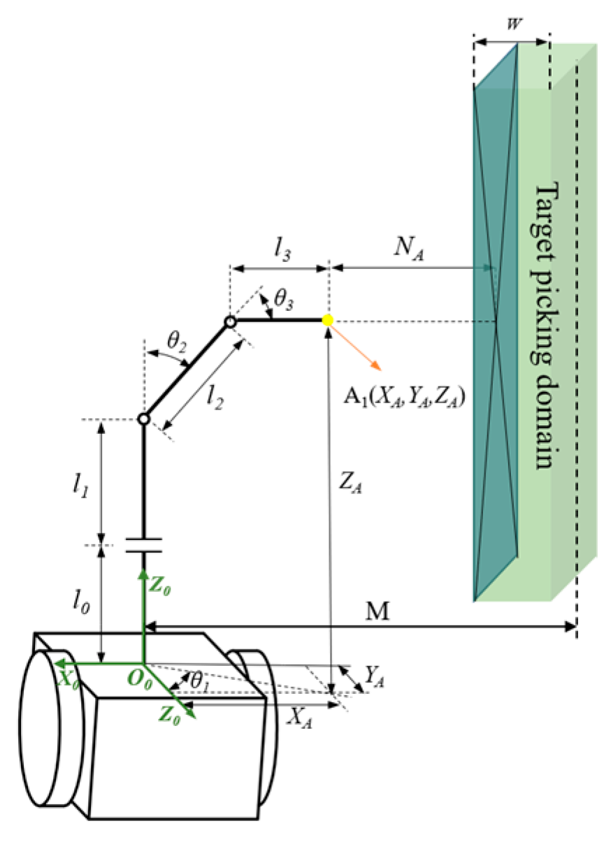
To simplify the forward kinematic model of the fruit-picking mechanism, a base coordinate system O0′X0′Y0′Z0′ has been established. Additionally, to accurately determine the picking point location, an auxiliary coordinate system O8X8Y8Z8 has been introduced.
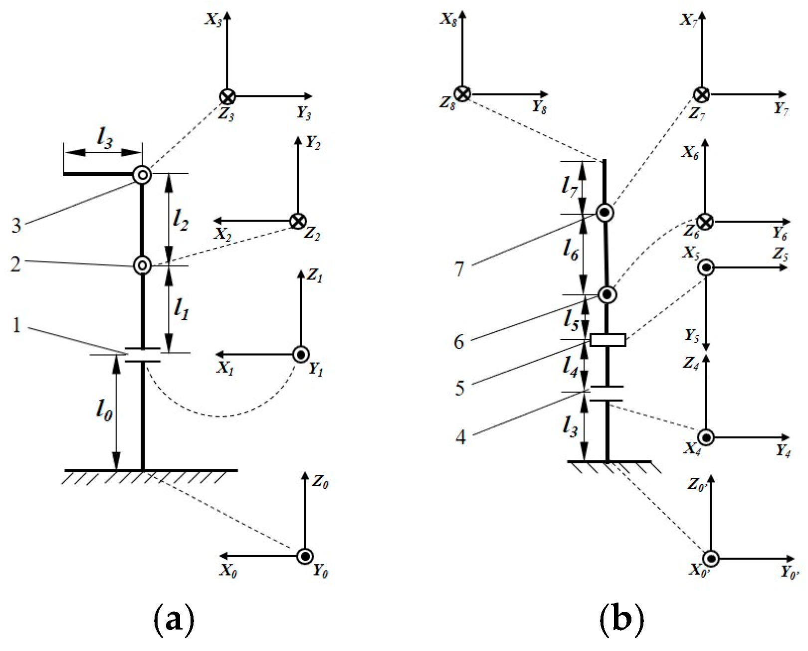
Agriengineering 07 00135 g008
Figure 9. Geometric solution diagram of picking base point positioning mechanism.
Agriengineering 07 00135 g009
Figure 10. Random point-geometry fusion inverse solution method. The green, yellow, red and blue areas shown in the figure represent the four pose regions in sequence (i~iv).
Agriengineering 07 00135 g010
Figure 11. Structure diagram of the picking device control system.
Agriengineering 07 00135 g011
Figure 12. Schematic diagram of the joint angle control principle.
Agriengineering 07 00135 g012
Figure 13. Motor drive control file format. Where: MN-start denotes the harvesting start identifier for the fruit tree labeled (M, N), while Treenumber-MN serves as the identifier for the tree itself, where M and N represent the row and column numbers, respectively. Locatingangle is the spatial base point identifier for harvesting, with N1, N2, and N3 corresponding to the control signals for the rotation angles of the Supporting Arm (θ1), Elevating Arm (θ2), and Secondary Rotation Arm (θ3), respectively. Fruitangle-i and Fruitdisplacement-i represent the coordinate point identifiers for the i-th fruit. The associated control signals include N4, N5, N6, and N7, which correspond to the rotation angle of the Primary Rotation Arm (θ4), the translational distance of the Translation Arm (ex5), the rotation angle of the Main Fruit Harvesting Arm (θ6), and the rotation angle of the Auxiliary Fruit Gripping Arm (θ7), respectively. MN-end indicates the harvesting end identifier for the fruit tree labeled (M, N).
Agriengineering 07 00135 g013
Figure 14. Automatic fruit picking mode flow chart.
Agriengineering 07 00135 g014
Figure 15. Schematic diagram of the picking area.
Agriengineering 07 00135 g015
Figure 16. Mixed Beta distribution. (a) Probability density function image; (b) Distribution simulation.
Agriengineering 07 00135 g016
Figure 17. ADAMS simulation model of fruit picking mechanism 1. primary rotation arm 2. translation arm 3. main fruit harvesting arm 4. auxiliary fruit gripping arm.
Agriengineering 07 00135 g017
Figure 18. Experimental site for position tracking test. 1. Harvesting Device; 2. High-Speed Camera; 3. ThinkBook Mobile Computer.
Agriengineering 07 00135 g018
Figure 19. Harvesting Experiment Site. The red box part in the figure represents the soft-ware interface for the program to run.
Agriengineering 07 00135 g019
Figure 20. Harvesting domain expansion volume. (a) Schematic of the expansion shapes for V1 and V2; (b) Schematic of the expansion shapes for V3 and V4.
Agriengineering 07 00135 g020
Figure 21. Composite diagram of the simulated domain of fruit-picking reference points. (a) 3D harvesting domain; (b) xoy projection plane; (c) xoz projection plane; (d) yoz projection plane.
Agriengineering 07 00135 g021
Figure 22. Simulation of Driving Force and Torque. (a) Primary rotation arm; (b) Translation arm; (c) Main fruit harvesting arm; (d) Auxiliary fruit gripping arm.
Agriengineering 07 00135 g022
Figure 23. Partial frame images of reference point localization by high-speed camera. (a) Frame 1; (b) Frame 5940; (c) Frame 11,880; (d) Frame 17,820; (e) Frame 23,760; (f) Frame 19,700; (g) Frame 35,640; (h) Frame 41,580.
Agriengineering 07 00135 g023
Figure 24. Partial frame images of the reference point for fruit picking captured by high-speed camera. (a) Frame 1; (b) Frame 4520; (c) Frame 9040; (d) Frame 13,560; (e) Frame 18,080; (f) Frame 23,600; (g) Frame 27,120; (h) Frame 31,640.
Agriengineering 07 00135 g024
Figure 25. Comparison of calculated and measured values for the X and Z axes. (a) X axis; (b) Z axis.
Agriengineering 07 00135 g025
Figure 26. Comparison of measured and calculated values for the fruit picking reference point in the X, Y, and Z directions. (a) X axis; (b) Y axis; (c) Z axis.
Agriengineering 07 00135 g026
Table 1. Apple Tree Morphological Parameters.
NameFruit Tree Row SpacingPlant SpacingFruit Tree HeightCrown WidthCrown Thickness
Fruit Tree Shape
Spindle tree shape3.5~4.2 m1.0~1.2 m2.8~3.1 m1.0~1.5 m1.0~1.2 m
Hedge tree shape3.6~4.2 m1.5~1.7 m2.7~3.2 m1.4~1.6 m0.4~0.6 m
Table 2. Main technical parameters of picking device.
ParameterValue
Suitable planting row spacing/m2.5~3.5
Working height/m2.4
Working width/m2.0~2.1
Degrees of Freedom/piece7
Walking speed/m·s−10.9~1.1
Table 3. Fruit-picking mechanism joint range parameters.
NameRange
primary rotation arm angle (θ4)[−180°, 180°]
translation arm displacement distance (ex5)[−100 mm, 100 mm]
main fruit harvesting arm angle (θ6)[−90°, 90°]
auxiliary fruit gripping arm angle (θ7)[−120°, 120°]
Table 4. D–H parameter table of harvesting reference point positioning mechanism.
Joint Numberθi/(°)di/mmai/mmαi/(°)Joint Range
00l0000
1θ1l1090[−45°, 45°]
290 + θ20l20[30°, 105°]
3−90 + θ30l390[−60°, 60°]
Where, αi (i is the joint number, the same below) is the rotation angle of rotation of the Zi−1 axis counterclockwise around the Xi−1 axis to the Zi axis, (°); ai is the distance from the Zi−1 axis along the Xi−1 axis to the Zi axis, mm; di is the distance from the Xi−1 axis along the Xi axis to the Zi axis, mm; θi is the rotation angle of rotation of the Xi−1 axis counterclockwise around the Zi axis to the Xi axis, (°) with the same meaning for subsequent joints.
Table 5. D–H parameter table of fruit-picking mechanism.
Joint Numberθi/(°)di/mmai/mmαi/(°)Joint Range
30l3000
4θ4l4090[−180°,180°]
590ex5l590[−100 mm,100 mm]
6θ50l60[−30°,30°]
7θ60l70[−120°,120°]
Table 6. Picking experiment results.
GroupNumber of Successful FruitsPicking Success Rate/%Time for Single-Domain Picking/sAverage Time for Single Fruit Picking/s
14378.7316.57.36
23577.12467.05
34175.93007.32
43675.62647.34
53978.72787.13
64176.6298.57.28
73575.42577.34
83677.42687.44
94373.5303.57.06
103876.42717.14
Average value76.53 7.24
Standard Deviation1.5720 0.1385
Coefficient of variation2.06% 1.91%
Note: The single-domain picking time refers to the total time taken to harvest all the fruits within the designated picking area.
Disclaimer/Publisher’s Note: The statements, opinions and data contained in all publications are solely those of the individual author(s) and contributor(s) and not of MDPI and/or the editor(s). MDPI and/or the editor(s) disclaim responsibility for any injury to people or property resulting from any ideas, methods, instructions or products referred to in the content.

