Article

A Study of an Agricultural Indoor Robot for Harvesting Edible Bird Nests in Vietnam

by
Duc Anh Vu Trinh
1 and
Nguyen Truong Thinh
2,*
1
Department of Electrical Engineering, University of South Florida, Tampa, FL 33620, USA
2
Institute of Intelligent and Interactive Technologies, University of Economics Ho Chi Minh City—UEH, Ho Chi Minh City 700000, Vietnam
*
Author to whom correspondence should be addressed.
AgriEngineering 2024, 6(1), 113-134; https://doi.org/10.3390/agriengineering6010008
Submission received: 27 November 2023 / Revised: 27 December 2023 / Accepted: 4 January 2024 / Published: 12 January 2024

Abstract

:
This study demonstrates robot technology for harvesting edible bird’s nests within swiftlet houses. A comprehensive manipulator’s movement analysis of harvesting operation with a separating tool is provided for precisely collecting swiftlet nests. A robotic manipulator mounted on a mobile platform with a vision system is also analyzed and evaluated in this study. The actual harvesting or separating the swiftlet nests is performed with visual servo feedback. The manipulator performs the gross motions of separating tools and removing the nests under computer control with velocity and position feedback. The separating principle between the objective nest and wooden frame has been applied to a demonstration removal of nests using a four-degrees-of-freedom manipulator to perform the gross movements of tool. The actual separations using this system are accomplished as fast as the manipulator can be controlled to perform the necessary deceleration and topping at the end of separating. This is typically 2.0 s. This efficiency underscores the system’s capability for swift and precise operation in harvesting an edible bird nest task.

1. Introduction

In the past, robots were mainly for increasing productivity and expanding production capacity under fast growing necessaries. But, in recent years, we are facing the necessity of developing a new concept for the introduction of robots into harvesting swiftlet nests. We understand that one of the new goals of the robots from social issues is to promote automated robots instead of labor increase. On the other hand, humans make mistakes when harvesting swiftlet nests. In this case, the decision to select a particular operation to be automated is made only by considering the technological possibility and economical desirability. Today, manual harvesting of swiftlet’s nests in the house causes many obstacles to the survival and reproduction of swiftlets. Moreover, manual harvesting completely depends on the experience of the harvester. The environment in the swiftlet farming area is quite toxic affecting human health, so the trends of automation in monitoring and harvesting of nests in the house is being researched and implemented. The edible bird nests are harvested from natural caves, and they are taken increasingly from purpose-built brick houses, which are designed and structured to attract swiftlets.
There are many species of avian that use its saliva grande as a component in nest buildings, but the swiftlet might be the extreme case where its nest is made entirely of the saliva. Out of numerous swiftlet species, namely the edible-nest swiftlet (Aerodramus fuciphagus), the black-nest swiftlet (Aerodramus maximus), the Atiu swiftlet (Aerodramus sawtelli), and others, only some of them whose nests are edible belong to the family Aerodramus fuciphagus. They frequently breed in the ceiling of caves or the edge of cliffs where they are not exposed to direct sunlight, but the majority of edible birds’ nests are now collected in artificial bird’s nest houses for higher productivity and lower hazard. The white translucent house’s nest is made of glutinous saliva solution that securely clings to vertical walls and is hardened over time. Nutritional studies [1,2] have shown EBN is mainly made of protein and carbohydrates with very low input of fat. Economically, EBN can fetch more than USD 2500 per kilogram, mostly produced in Southeast Asia, and the global bird’s nest industry is estimated to be worth USD 5 billion, mainly consumed in countries like China, Hong Kong, and Taiwan. The garnering of EBN in bird’s nest houses has yielded elevated income due to the nest’s expensive tag and reduced life-threatening risks related to cliff-climbing for farmers recently. However, manually harvesting the EBN, like most of the agricultural field, is repetitive, time-dependent, and labor-intensive, and can even have negative effects in maintaining the house bird’s population owing to the swiftlet’s dislikes of unfamiliar human odors. These difficulties can be resolved by an EBN harvesting robot since as proved by many real-world examples, utilizing a farming robot is faster, more accurate, and more efficient because of its inexhaustive and controllable characteristics.
Currently, in Southeast Asia, domestic swiftlet farming is being developed. Houses or factories for raising swiftlets are designed and built depending on investment costs and farming area. Like Indonesia [
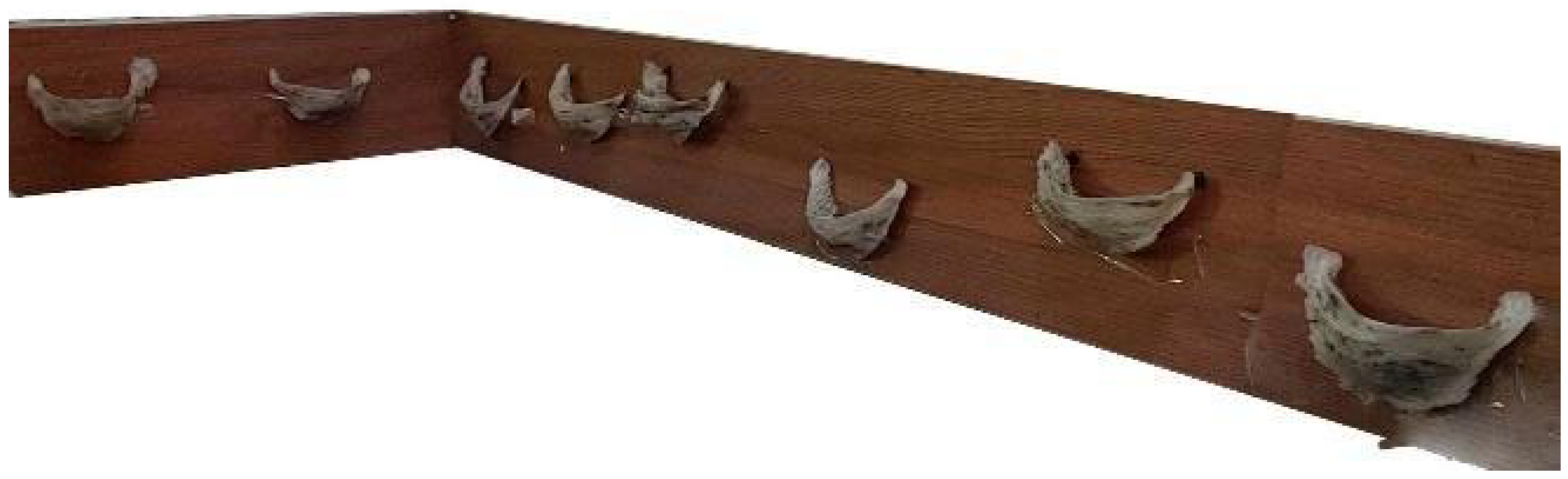
3], most of the swiftlet houses built in Vietnam are brick houses built with wooden trusses for birds to nest (Figure 1). The swiftlet house is built with a diverse scale with different number of floors from one to four floors. The minimum size of the nesting rooms is usually 8.0 × 16 m or 40 m. The height of each floor is usually 2 m, sometimes up to 2.5 to 3.0 m high. The formation of the nest begins with nesting and egg laying. The mother bird builds the nest by dripping saliva. When the nest is formed, the mother begins to lay eggs and then incubate. The chicks are incubated and hatched in the nest and cared for by their parents until they are ready to fly.
Since each agricultural product is harvested in a different environment, researchers have been developing solutions aimed at specific commodities. This is reasonable because each species has particular strength, size, and shape, which can make the method for one kind damaging for another. Although for many crops and fruits, agricultural robots are extensively studied and catered for, there is sparse research about harvesting robots that aim at EBN. Hence, it is of profound importance to develop a robotic system designed to automate the bird’s nest harvesting process of in-house environments [4].
A robot consists of different sub-systems such as the mobile platform, manipulator, and end-effectors which are designed to match the task requirement and environment constraints. Each subsystem is reviewed from various literature, and this study’s automated system is presented thereafter. Smart agriculture is the use of smart technology applied to agriculture with the aim of saving labor and improving product quality and productivity. The caring for and raising of swiftlets for nesting is an agricultural profession developed in Vietnam. Therefore, the care, monitoring and harvesting should use AI with Machine learning to ensure sustainable development in agriculture.
A study [5] makes a review of the design of manipulators used in harvesting robots, which shows that electric servo and stepper motors are mostly utilized when the weight load is light, whereas the custom electric actuator or hydraulic motor is used in the opposite situation. Additionally, [5] also lists three requirements to consider when designing the manipulator, which are adaptable enough for the working environment, vigorous enough for the required forces, and sustainable enough against the environment’s condition. To correctly control the manipulator, kinematics and inverse kinematics models need to be calculated, so [6] utilizes the Denavit–Hartenberg model for the path planning of cucumber harvesting. The end effector is the interaction part between the product and the robot, so its design needs to be delicate enough to not impair the product but powerful enough to extract the product from the main body. According to [7], the fruit harvesting method commonly utilizes one made out of product grasping, stem grasping, rotation mechanism, cutting devices, and pressure suction as its main development. Grasping, suction, and rotation alone cannot be applied to EBN harvesting since the approach will easily break the nest due to the nest’s strong adhesion to the wooden cell of EBN house. The cutting mechanism, however, is harder to implement in fruit harvesting because good stem detection is required. Refs. [8,9] develop a thermal blades solution by creating a voltage between electrodes in which both uphold the gripper structures to stabilize the product before the cutting process. Meanwhile, reference [10] chooses a high-speed mechanical rolling blade to cut off the pumpkin’s stem. Four-wheel vehicles are dominant in developing a harvesting robot [11] because of their light weight and flexibility for dampish conditions. Likewise, track vehicles are less sensitive to the ground environment, so it can work well in swampy and wet ground quality [12]. Due to more pressure on the ground, the crawler-type wheel has an advantage when working on rough terrain compared to that of the four-wheel [13]. Six-wheel steering is also used when high maneuverability is demanded on unpredictable terrain. Additionally, ensuring that all wheels sustain contact with the ground in any circumstances is a crucial design requirement. Ref. [14] designs a flexible platform frame that is slightly bendable when contacting with inclined ground. Many systems for fruit harvesting in a greenhouse use a rail mobile platform to travel due to the organized rows of crops, such as in [12]; so the path is always determined and slipping is minimized compared to the wheel-type system. If the wheel-type or crawl-type wheel is used, path planning incorporated with landmark detection needs to be executed. As such, [13] with crawl-type wheel uses the GNSS and LiDAR sensors to determine the location of ground turn and orchards row-turn respectively, and the robot’s path is tracked continuously. Path planning for a robot system working on farmland is developed in [14]. Many systems in greenhouses use rail mobile platforms to travel due to the organized rows of crops, such as in [15]. Therefore, the path is always determined and slipping is minimized compared to wheel-type system. If the wheel-type or crawl-type wheel is used, path planning incorporated with landmark detection needs to be executed. As such, [16] with crawl-type wheels uses the GNSS and LiDAR sensors to determine the location of ground turn and orchards row-turn respectively, and the robot’s path is tracked continuously. Due to the flourishing of machine vision, a large number of harvesting solutions use vision-based methods. When combining color and geometric features of the target, fruits like tomato, apple, citrus, and lichi get correctly detected with a precision over 90% as mentioned in [17] which provide a review of object recognition approach. Nevertheless, camera-based still faces difficulties in ambient light and various illumination conditions, so LiDAR-based is frequently selected as an alternative. Ref. [18] applies cartographer algorithm in ROS for local SLAM and loop-back detection to LiDAR’s point cloud, and Publish Point function in ROS combined with Dijkstra algorithm is applied for global and local path planning. Path planning constrained by different limits for a robot system working on farmland is developed in [19].
The swiftlet bird builds its nest from saliva strands, but only some of the swiftlet species’ nests are proved to be edible and harvested, which majorly comprises glycoprotein to which galactose, galactosamine, and other carbohydrates attach [20]. Moreover, the nest cement has enough adhesive properties when dried up to hold against its weight and the bird’s egg. Specifically, the nest’s adhesive strength overall can load a vertical force of around 0.465 N considering the heaviest case scenario of two birds’, two eggs’, and the nest’s weights. Paper [21] calculates the maximum stress in this scenario to be 0.56 MPa at the rim where the birds stand. However, there is a limited source for the adhesiveness of the nest to the wooden frame partly because the sample is normally analyzed in the laboratory. Therefore, the actual force to separate the nest in the harvesting site is not regenerated. When each component is brought together, a control unit fuses the data and decides the reaction of those peripherals. Ref. [22] provides the general control system for apple harvesting robot, but the graph can be applied to most harvesting robots.

2. Swiftlet-Nest Harvesting Robot

This study introduces the design and planning of movement paths based on reinforcement deep learning to address the significant challenge of harvesting swiftlet nests in a combined environment of structured and unstructured spaces, ensuring that the robot can harvest targeted bird nests without colliding or interacting with neighboring nests. The recurrent neural network is applied to recollect and find the past state observed by the computer vision system and determine depth according to the gradient algorithm to yield the appropriate movement. The task of this study is to plan a collision-free path, which consists of a sequence of regression reference points, into the mixed environment after the position of the interested object is determined.
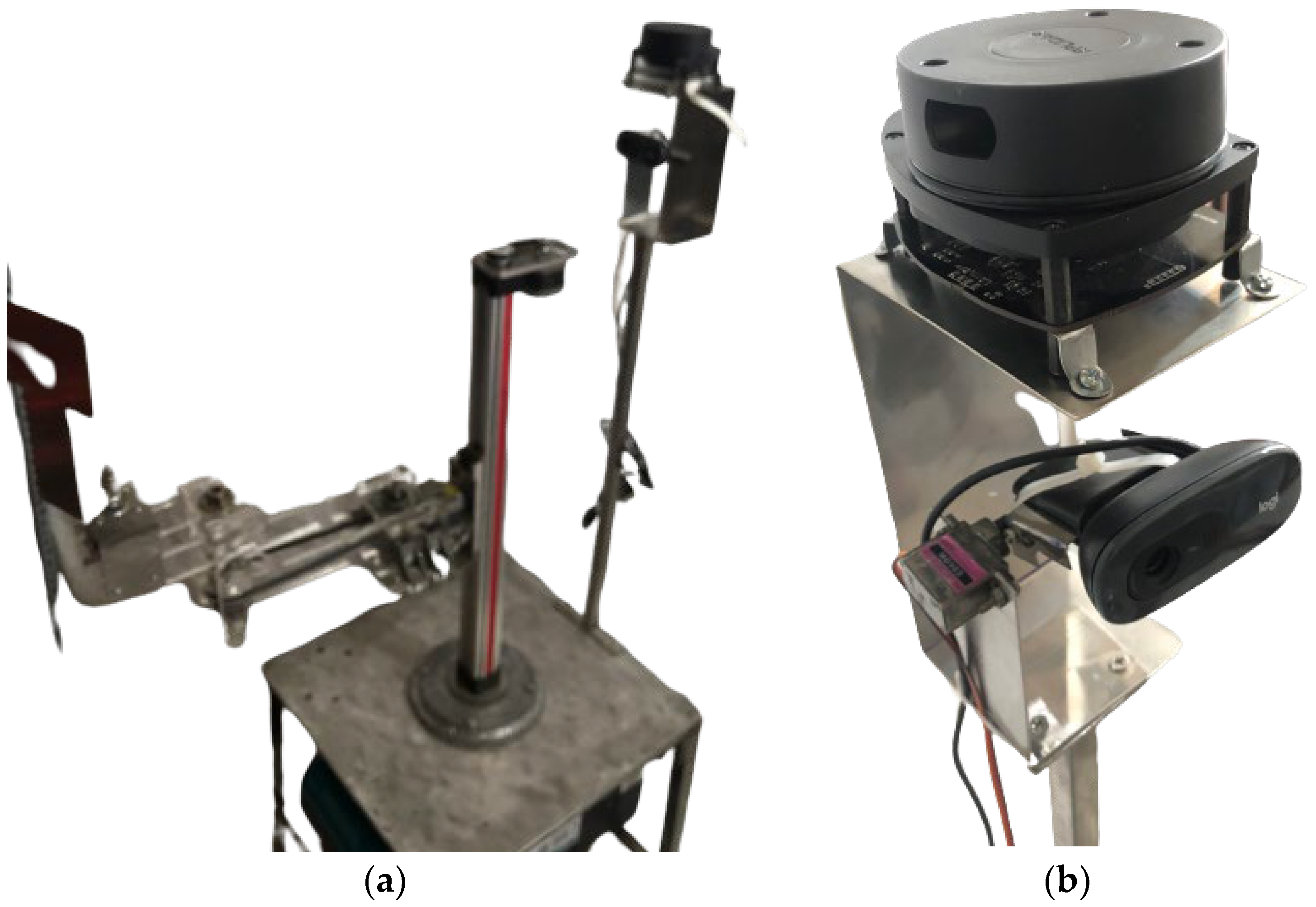
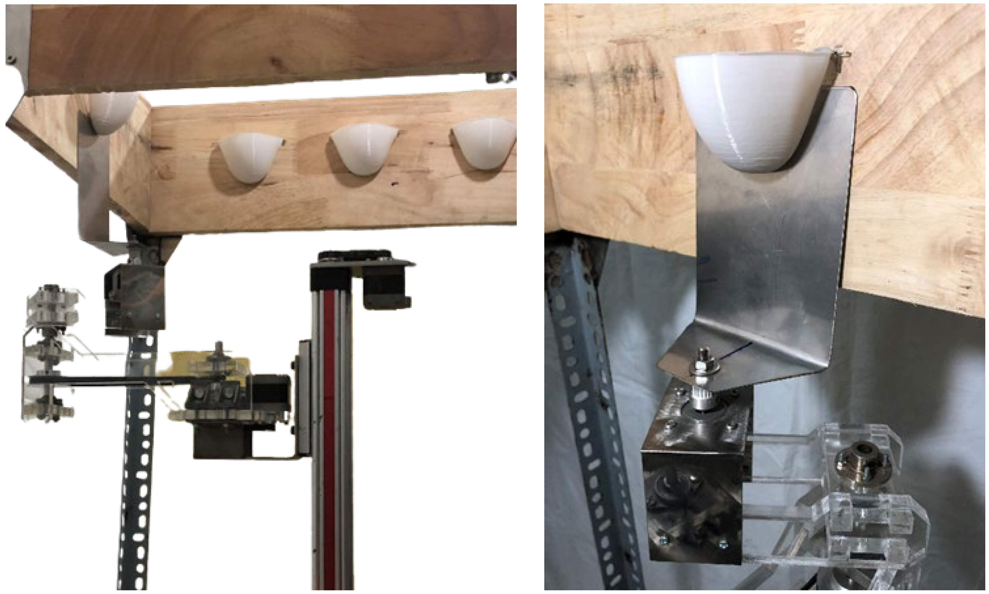
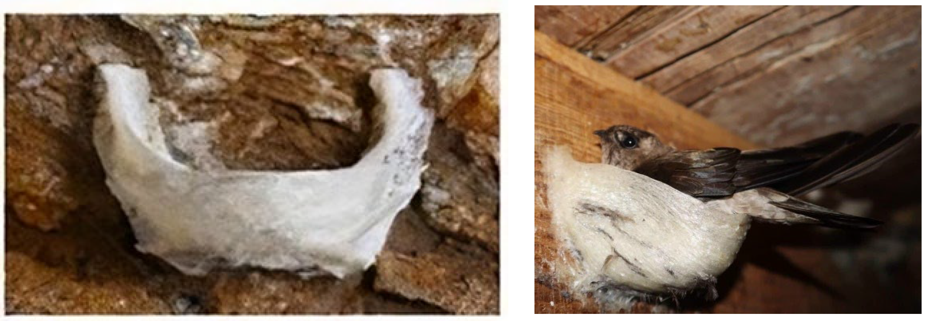
Figure 2 depicts the structure of the designed bird’s nest harvesting robot. It consists of a moving platform, vision system, and manipulator, which are the main parts of swiftlet-nest harvesting robotic system. The vision system and manipulator are both integrated and firmly fixed on the moving platform. The mobile platform is made of an aluminum platform with three wheels including two active wheels and a caster wheel moving according to differential drive. The moving platform, manipulator, and vision system are controlled by a central controller unit (CPU) that communicates with the computer via a universal asynchronous receiver–transceiver (UART). The moving platform carries the robot arm and vision system to the desired position under the control of the CPU. The robotic structure is designed to be suitable for the size of the birdhouse space as well as the workspace of the manipulator. The nests are mostly located on the walls of the swiftlet-house, so harvesting nests is a sequence of the tool’s movements to the position beneath the nest, followed by a lateral movement along the wall to perform the harvest. Thus, the required manipulator should have four degrees of freedom: three translational movements in cartesian space and one rotation about the vertical axis to be able to apply the tool’s force to the wall. To perform the harvesting function, a device, similar to a scraper, is used to separate the nest from the wall, which is considered as the end-effector of the manipulator. The bird’s nest separating tool resembles a shovel, while the cup mimics a human bird’s nest harvester. To expand the workspace of the manipulator, the tool is placed on a moving platform, effectively extending the operational space reach within the swiftlet-house. To perform the bird’s nest recognition, positioning, and navigating the robot, the camera system can translate in the vertical axis and is also mounted on the moving platform. Therefore, the field of view of the robot can be greatly expanded. Swiftlet’s nest has long been a culinary delight in many countries and tagged with a high price due to its supposed health benefits. Traditionally, they are harvested from natural cliffs, which is extremely dangerous and requires safety gears to collect high-built nests up in the cave’s ceiling. Therefore, man-made houses are constructed to duplicate the natural living condition of the swiftlet so that the bird is attracted to nest in this guarded space. The swiftlet first builds an anchor from its saliva gland that is hardened and adhered to the high wooden house’s frame when exposed to the air. Thereafter, it weaves the nest around the spot to form a semi-cup shape that firmly sticks to the frame along the nest’s boundary [23]. To harvest bird nests, the collectors need to have a specialized knowledge of the suitable time and nest’s maturity level. Because of the nest’s persistent adhesiveness, the collectors usually use a thin scraping tool to gently detach the nest from the frame by delicately pushing and picking between the nest and its gluing surface. As such, the same method with a non-abrasive and fine tool is applied as the robot’s end effector to undisturbed applied force from the bottom of the nest. When there is sufficient force, the nest-frame adhesive bond is breakable, and the nest can be collected.
Due to the asynchronous formation of nests, not all of them can be harvested, which constitutes a significant challenge in this study. The selection of the candidate bird’s nest to harvest is based on its size and formation time to ensure quality and precise operation. The weight of the bird’s nest is very light, and it is very easy to break due to strong impact force. Therefore, careful attention, flexibility, and meticulousness must be given to ensure precise and accurate harvesting operations when employing a robot for this task. To harvest the bird’s nest, the end-effector, or a tool as simple as a blade, can separate the bird’s nest from the wooden frame of the house, safely assumed to be flat surfaces.
The separation process of harvested swiftlet nests from the surface of frames is completed by using the tool attaching manipulator. In order to analyze the process in detail, its two-dimensional modeling is presented in Figure 3. In this idealized modeling the separating tool moves bottom to top along the swiftlet nest at a constant velocity V. The nest is removed from the frame by a tool based on the shearing of the nest’s adhesive layer continuously along the shear plane. The forces and power involved in separating operations is significantly important since power requirements must be known to enable the calculation of the manipulator’s dynamics with adequate power. Equally crucial, the separating forces are required without excessive distortion so that the nest’s shape is intact. The forces acting on the tool are shown in Figure 3. The cutting force Fc acts in the direction of the removing speed V and supplies the energy required for the harvesting process. The thrust force Ft acts in the direction normal to the separating velocity, that is, perpendicular to the frame. These two forces produce the resultant force R. The resultant force can be resolved into two components on the tool face: a friction force F along the tool-nest interface and a normal force N perpendicular to it. Another way is to resolve into the shear force Fs along the shear plane and a normal shear force Fs, n perpendicular to it. This paper assumes that the width of the adhesive layer before and after the shearing process is almost identical. Therefore, if the rake angle, α, is between the tool’s surface and the perpendicular direction of the frame, then the shear angle, β, is calculated by (1), and the shear force is determined by (2).
tan 1 cos ( α ) 1 sin ( α )
F c cos ( β ) F t sin ( β )
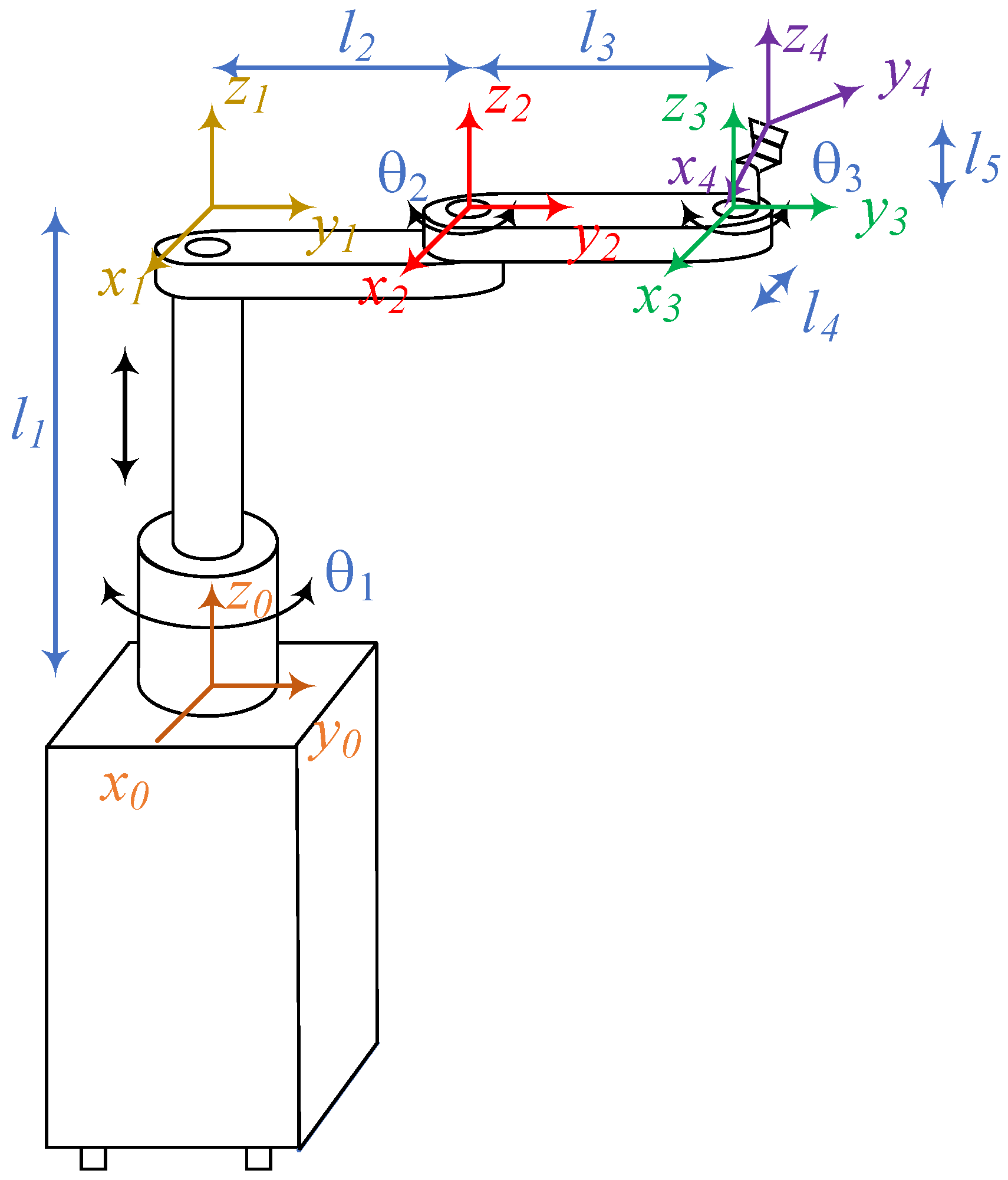
During the harvesting operation of the manipulator, the separating tool attaching to the manipulator can reach the swiftlet nests in its workspace. In this study, a manipulator named modified SCARA with four degrees of freedom was used as a harvesting manipulator. A modified SCARA manipulator is generally represented in the form of an open loop kinematics linkage. It includes four degrees of freedom presenting a multivariable mechanical system. The manipulator should copy the movements of the human arm harvesting the edible swiftlet’s bird in the house. The number of degrees of freedom of the arm is in the range of 6 ≥ n ≥ 3. The movement of two human arms holding the swiftlet separating tool for harvesting is quite flexible and has high DoFs. The number of DoFs is modeled, and each joint must have a reference system of axes that includes the z and x axes. There are several concepts, but the modified SCARA is selected with three rotating joints, and a translation one. We can model the coordinate system of the manipulator (Figure 4) according to the rotation using the anatomy and representation of the coordinate system and the rotation joints in the human body. Each joint is given a set of coordinate axes.
Before a dynamic system is constructed, it is essential to carry out the analysis and synthesis on the mathematical model of the system. Like the concept presented in the previous section, it described an end-effector moving along a vertical wooden wall. The task space coordinate system is given in the u and v directions. In this case, the tool is moved along the surface in the v direction and normal force is applied to the surface along the u direction. The vector of task space is x, the correlation defined the forward kinematics is defined as follows:
x = x y z β = φ q i i = 1 4 ;
where φ : 3 3 .
In this study, the coordinate systems for the joints and links of the 4-degrees-of-freedom manipulator follow the Denavit–Hartenberg (D–H) rule. Since the four axes of joints are parallel, the axes are assigned as shown in Figure 4. During the bird’s nest harvesting operation of the robotic manipulator, the separating tool of manipulator can reach the nest locations so that it can be harvested in the workspace and perform harvesting operation in-sequence. With the configuration of the modified SCARA manipulator of 4 degrees of freedom, it can perform translational movements along the x, y, z axes and rotation around the z axis. The manipulator is generally presented in the form of an open loop kinematics. Theoretically, SCARA would be required to separate an object attaching the other one with a desired orientation to find the position of the end-effector based on the rotation angles of the manipulator’s joints and is a forward kinematics problem. The parameters of the D–H table are based on the poses of the coordinate attached to the joints. The coordinate transformation between two consecutive frames i and frame i + 1 is obtained as follows.
According to the parameters of the manipulator based on the D-H method, the forward kinematics equation of the manipulator is formed by multiplying the matrix of transformation matrices. The result of the forward kinematics equation is as below.
  n + 1 n T = sin ( θ n + 1 ) sin ( θ n + 1 ) cos ( α n + 1 ) sin ( θ n + 1 ) sin ( α n + 1 ) a n + 1 cos ( θ n + 1 ) sin ( θ n + 1 ) cos ( θ n + 1 ) cos ( α n + 1 ) cos ( θ n + 1 ) sin ( α n + 1 ) a n + 1 sin ( θ n + 1 ) 0 sin ( α n + 1 ) cos ( α n + 1 ) d n + 1 0 0 0 1
T 4 0 = T 1 0 T 2 1 T 3 2 T 4 3 = cos θ 1 + θ 2 + θ 3 sin θ 1 + θ 2 + θ 3 0 l 2 sin θ 1 l 3 sin θ 1 + θ 2 sin θ 1 + θ 2 + θ 3 cos θ 1 + θ 2 + θ 3 0 l 2 cos θ 1 + l 3 cos θ 1 + θ 2 0 0 1 l 1 0 0 0 1
When the robot arm is in operation, the separating tool must be correctly controlled with the required speed of displacement and vertical upward movement. The impact forces and velocity of the tool are carefully calculated to ensure the quality of the harvested bird’s nest. After multiplying all the matrices together and simplifying the equation, the positions of the tool can be determined as follows:
P x = l 2 cos θ 1 + l 3 cos θ 1 + θ 2 + l 3 cos θ 1 + θ 2 + θ 3
P y = l 2 sin θ 1 + l 3 sin θ 1 + θ 2 + l 3 sin θ 1 + θ 2 + θ 3
P z = l 1 + l 5
β = θ 1 + θ 2 + θ 3
For the task of the nest’s separation from wooden frames by the manipulator, the position controller gives a responding performance because the task only requires the robot to follow a predetermined required trajectory. However, the manipulator contacts with the environment, so there are the interaction forces between the separating tool mounted on the end-effector and the environment, so the interaction force and position of the separation tool need to be controlled. To separate the nests for harvesting, the position of the tool should be controlled. That is, insufficient press can result in adhesion that is not easily separable, while excessive pressure can lead to the nest’s breakage. Where ϕ(q) is forward kinematics, the derivative of x is defined.
x ˙ = J q q ˙
The relationship between the speed of the manipulator’s end-effector and velocities of angular and linear joints can expressed with the following equation by Jacobian matrix.
x ˙ = v ω ˜ = J q q ˙
In the study, the manipulator which uses the angular and linear joints can be shown.
v ω ˜ = z i × p n 0 i z i q ˙
J i = z i × p n 0 i z i
where Ji is the ith column of Jacobian matrix, p is the position vector of the origin in the coordinate system of the manipulator relative to the coordinate system {i} in the base coordinate system. The zi denotes the unit vector of the z-axis of the coordinate system {i} in the base coordinate system. The dynamic model of the manipulator with 4 degrees of freedom, rigid, with no friction at the joints is shown below.
M q q ¨ + C q , q ˙ q ˙ + g q = τ
The state vector q T q ˙ T is modified as follows:
d d t q q ˙ = q ˙ M q 1 τ t C q , q ˙ q ˙ g q
The Jacobian matrix in n × n task space is defined as follows:
J q = I 0 0 T φ q q
where, I is the identity matrix and T is transformation matrix.
In addition, we can determine the Jacobian matrix with four variables as joints. From the positions and orientation obtained, the relation between the velocities is shown in below.
x ˙ y ˙ z ˙ β ˙ = x θ 1 x l 1 x θ 2 x θ 3 y θ 1 y l 1 y θ 2 y θ 3 z θ 1 z l 1 z θ 2 z θ 3 β θ 1 β l 1 β θ 2 β θ 3 θ ˙ 1 l ˙ 1 θ ˙ 2 θ ˙ 3 = J q θ ˙ 1 l ˙ 1 θ ˙ 2 θ ˙ 3 = J q
And the Jacobian matrix is determined as follows:
J q = l 2 sin θ 1 l 2 sin θ 1 + θ 2 l 2 sin θ 1 + θ 2 + θ 3 0 l 2 sin θ 1 + θ 2 l 2 sin θ 1 + θ 2 + θ 3 l 2 sin θ 1 + θ 2 + θ 3 l 2 cos θ 1 + l 2 cos θ 1 + θ 2 + l 2 cos θ 1 + θ 2 + θ 3 0 l 2 cos θ 1 + θ 2 + l 2 cos θ 1 + θ 2 + θ 3 l 2 cos θ 1 + θ 2 + θ 3 0 1 0 0 1 0 1 1
where J q = φ q q 4 × 4 is called the analytical Jacobian matrix, and the relation of acceleration also called the differential kinematics is as follows:
x ¨ y ¨ z ¨ β ¨ = d d t J q θ ˙ 1 l ˙ 1 θ ˙ 2 θ ˙ 3 + J q θ ¨ 1 l ¨ 1 θ ¨ 1 θ ¨ 1
The inverse kinematics model of the harvesting manipulator allows for obtaining the joint positions q in terms of the positions and orientation of tool attaching on the end-effector in the reference frame. The inverse kinematics is below:
θ 1 l 1 θ 2 θ 3 = φ 1 x , y , z , β
where φ 1 : q 4 and q 4 .
The derivation of the inverse kinematics model is very complex and contrasts with the forward kinematics. The angular and linear accelerations and velocity of joints are determined according to recursive relationships. For each joint, inertial forces and the moments are calculated, and equations of kinematics are established. The configuration of the separating tool as the end-effector is described by a position and an orientation.
In order to reduce the impact force on the manipulator during operation as well as improve movement’s stability, it is required that the trajectory of the end-effector and active joints of the manipulator have to be continuous and smooth. Therefore it should not have any sudden change in velocity and acceleration. When the separating tool harvests the nests, the path of the end-effector is optimally designed based on the information provided by the LiDAR system. The LiDAR collects the point clouds and then calibrates the position and orientation to give a suitable map. Information about the nesting parameters is located in the three-dimensional coordinates of swiftlet nests in workspace. After completing harvesting for each nest, the robot system returns to its initial position. The operation of harvesting the swiftlet nest is divided into three stages as follows. First, the separating tool is moved to the target (below the nest). Secondly, it is moved along the vertical axis from bottom to top. Finally, the tool is moved back to its original position. At each stage in the harvesting process, path planning is performed based on quintic polynomial interpolation. To ensure that harvesting does not affect the quality of the bird’s nest, the speed of the tool must be controlled. The transport processes play an essential role at automated swiftlet nest harvesting, especially in moving the manipulator to suitable position determined by LiDAR’s data, when the mobile platform is to be transported after finishing one operation to the next to be performed. The mobile platform moves along the stationary wall in the house facilities’ handling of individual harvesting based on mapping from LiDAR. Works provided with a permanent internal transportation system are consequently forced to produce their products in long series and are so unable to adapt flexibly, without a cost increase, to the requirements of customers. The mobile robot has a virtual tracking system which conveys information as robot deviation from the direction and position given by the map to the control system.
In this study, a wheel mobile robot on the ground is used, its wheels move by only rotation and no slip in driving and lateral directions. There are two concepts for designing the mobile platform as differential and tracking drive. The differential drive is simpler than the other one. The differential drive is always in contact with the ground by three contact points. The drive has the advantages over the tracking drive due to larger contact surface between its wheels and ground, assuming no wheel slipping when changing direction. Therefore, a tracking drive is often used for rough ground with big obstacles which the robot cannot overcome. We need to integrate the robot’s movements over time to determine its position accurately. Additionally, this research section considers the dynamics of the mobile robot system to address the challenges of controlling the robot’s motion in an environment that involves impact forces. Even though wheel slip is a factor that reduces the accuracy of evaluating and estimating the robot’s motion, when traveling at low speed, the effect of wheel slip relative to the road surface can be ignored. Wheeled robots move along the x-axis and the robot cannot move along the y-axis, and the position of the robot can be determined as the midpoint between the two active wheels. When the robot is moving, we will assume rolling without slipping on flat ground at low speed (5 km/h); therefore, the force of inertia in all directions is less than the force of friction. Under the differential drive system, the motion of the vehicle is determined by the control of wheel velocities. In order for both drive wheels to roll properly, the robot must rotate around a point situated on the common axis of the two wheels. By adjusting the relative velocity between the two wheels, the location of this rotation point can be changed, allowing for different trajectories of the vehicle. From the forward kinematics, it is possible to calculate the pose of the robot at any time t based on the control of the velocity of the left wheel and the right wheel. In general, the differential drive robot’s ability for moving in a specific direction θ(t) at a certain velocity is governed by the following equations.
x t = 1 2 0 t v r t + v l t cos θ t d t
y t = 1 2 0 t v r t + v l t sin θ t d t
θ t = 1 l 0 t v r t v l t d t
Therefore, the angular and linear velocity is calculated in the equation below:
V ω = cos θ P y P x sin θ sin θ + P y P x cos θ 1 P x s i n θ 1 P x cos θ K P x x r e f x P K P y y r e f y P
where linear and angular velocity are V, ω of the robot.
The dynamics of the robot are determined by the non-holonomic constraint. In this study, a differential drive mobile robot is the approached object. The robot’s center of gravity is placed in the midpoint between two wheels. Each wheel is controlled independently by the motor and the castor wheel has the ability to keep the robot’s balance while it is moving on the flat floor. Our robot is shown in (Figure 5) with 2b as the distance between two wheels, R is the radius of each wheel, θ is the angular between x-axis and robot orientation. Assume that the robot does not slide on any axis. From this assumption, the robot is described below.
x ˙ C cos θ y ˙ C sin θ = 0
x ˙ C cos θ + y ˙ C sin θ = r 2 φ ˙ r + φ ˙ l
The equation of dynamics is written by the following:
M q q ¨ + C q , q ˙ + G q + τ d = B q τ + A T q λ
where M(q) is the inertial matrix, AT is the Jacobi matrix, B(q) is the transpose matrix, τ is the moment, λ is the force vector, C q , q ˙ is the matrix containing radial and rotational components, G(q) is the gravity matrix, τd is the disturbance elements, and q is the status vector.

Scanning System Based on LiDAR

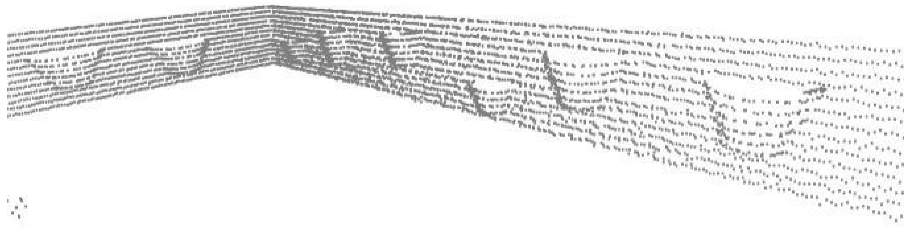
Dissimilar to the camera, LiDAR is not susceptible to dim or dark light conditions in the bird’s nest house, so it is employed in this study. A 3D map shown in Figure 6 is created from mounding distinct height levels of 2D layers that are generated from LiDAR’s point cloud for the vision capabilities of the robot. Since the data can be obstructed by both the environment’s condition and its calibration, which introduce noise, outlier points are removed by counting the number of the surrounding points and comparing it to a limit. As each 2D layer of the wooden frame is obtained, the line segment algorithm is applied to detect the frame portion between two nests, and the nest intersection is the complement of the frame line. Consequently, a 3D segment of the bird’s nest is acquired, and the nest’s position can be interpolated for harvesting process.
Line segmenting from the point cloud algorithm has been researched for many years with different approaches, so utilizing which method is a matter of choice regarding complexity and accuracy. Reference [22] reviews multiple research studies about line extraction from 2D sets of points and compares those algorithms on the same scanned LiDAR data. The incremental algorithm idea, as mentioned in [23], is used in this study to extract points that are classified as belonging to a line. The pseudo code for the algorithm is as follows:
-
An initial 1…n number of points is fit to a line, added to current set, and the RMSE is calculated by (8) and compared whether it is less than a user-specified threshold. In this study, the threshold is chosen based on the standard deviation of the statistical error of the LiDAR points.
( f ( x ) Y ) 2
-
If 1. is true, the next point is added to the current set, and the change in RMSE is recalculated to test whether it belongs to the current set.
-
If next point cannot be added, either the length of current set needs to be larger than a threshold to be considered a line segment, or the current set is discarded.
-
If 1. is false, points 2…n + 1 are used instead of 1…n and step 1. is repeated.

3. Controlling the Robot for Harvesting

3.1. End-Effector Control to Get the Bird Nest

Presently, the best available method of performing most precision swiftlet nest operations, and in some cases the only available method, is manual harvesting labor. This paper describes a method based on engineering compliance which permits the manipulator to perform swiftlet nest harvesting operations quickly, simply, and economically. The actual harvesting or separating the swiftlet nests is performed with visual servo feedback. The manipulator performs the gross motions of separating and removing the nests with velocity and position feedback under computer control (Figure 6). The principle of separation between the object and wooden frames has been implemented in a demonstration of nest removal. This was achieved using a four-degrees-of-freedom manipulator to execute the broader movements of the tool The actual separations using this system are accomplished as fast as the manipulator can be controlled to perform the necessary deceleration and topping at the end of separating, which is typically 2.0 s.
To reduce the workload and improve work efficiency, the bird’s nest harvesting robot was developed with mobility and flexibility. By using computer vision and a manipulator placed on a mobile platform for bird nest identification and harvesting, laboratory experiments have verified the features of the robot bird’s nest. However, this study still entails certain limitations in the performance of the robot, requiring further research. Firstly, the robot works in a confined environment whose power relies on lithium-ion batteries, which affects the time of use as well as the power of the actuators. During the harvesting operation, the computer vision and lidar system remains inactive, rendering it impossible to determine whether the harvest process has been completed and whether the quality of the harvested swiftlet nest is affected. In addition, the uneven surface of the swiftlet house floor due to the solidified bird waste makes it difficult to steadily roll.

3.2. Control Position and Velocity of Manipulator

The simplest way to indicate the movement of a manipulator is a method called point to point. However, in controlling the harvesting of bird’s nests process, the separation device is required to go beneath the surface of the nest to adhere to the wooden wall, which requires a path in state space and its time parameterization to achieve. In the study, the movement path is defined as a straight line in state space connecting the initial point and the ending one to generate the required harvesting path. After obtaining the moving path, the inverse kinematics problem is applied to solve for the parametrical trajectories over time for control in the joint coordinates. Functional capabilities of a robot are broadly enlarged when a robot is supplied with sensing properties, but at the same time, supplying a robot with such properties demands the use of an artificial intelligence (AI) system. According to the algorithmic control concept, basing itself on the levels of normal dynamics and perturbed regimes, the manipulator control divides itself, due to its specificity into a normal dynamics level; level of perturbed regimes. The driving system of a manipulator is generally an active multi-link kinematic chain, which performs its action through a separating tool that interacts directly with the swiftlet nests to be manipulated. Any AI system of a sensible robot would include a whole set of standard “behavior” which is suitable to a wide range of situations and which, so far as it is possible. The tool directly interacts with the swiftlet nests to be manipulated. The operation of separating objects is a motional task combining joint working motions. Let us consider a case when the motion of the tool is determined by a sequence of Aj (j = 0, 1, …, m) as Appendix A. The coordinates θi describing the state of the kinetic chain, are connected to the coordinates xi of the tool by below equations.
F ς θ 1 , , θ m ξ = 1 , , 4
To separate the swiftlet nests from wooden frames, the movement of the tool is vertical on wooden frames. The line of tool movements has now been reduced to finding the sequence of configurations. Those configurations correspond to the positions of the tool in points Aj. Let us introduce the notion Ω to be called volume of motion.
Ω = i = 1 n a i t 0 t m φ ˙ i t d t
where ai is the coefficient of the ith coordinate. For pointwise description of tool motion, the functional may be expressed in the following form:
Ω = i = 1 n a i j = 0 m 1 φ i t j + 1 φ i t j
where tj is the moment of the time when the tool coincidence with the point Aj. We admit that within the intervals (tj, tj + 1) the generalized coordinates φi of the system vary monotonously.

3.3. Path-Planning of Mobile Robot

During the working process, the robot moves according to a predetermined trajectory combined with information from LiDAR to generate a suitable separating trajectory. The control system is driven by two individual electric motors controlled by signals issued by a map as well as tracking sensors. The mobile robot is propelled by these motors driving two wheels by differential drive. Servo motors applied as actuators in the moving platform ensure the control system can be used as driving. The mobile robot in autonomous driving can perform traveling along a predetermined path and stopping at calculated positions where the manipulator can reach to harvest the swiftlet nests. Moreover, the robot is capable of making stops at the charge docking station and negotiating crossover. It begins with the detection of growing nest sites by LiDAR and decides whether to harvest based on technical requirements of their sizes and dimensions. The positions and sizes of the nests are also collected through the time determined by the LiDAR in global coordinates, which is necessary for the evaluation of the harvest time as well as the use of the blockchain later. In monitoring operation, the mobile platform only carries LiDAR scanning in a zig-zag trajectory to generate the point cloud with an up and down movement along the x-axis. This is only to collect information to monitor the formation as well as change of performances of nests in the house. In addition, algorithms to identify and determine the parameters of the nest such as the positions and sizes are developed. After identifying the nests that can be harvested, a trajectory for harvesting the nests is given and decided by the quality evaluation. The harvesting is always reviewed and verified to determine the ID of nests. In cases of the nests located near each other, the harvesting process is affected due to the large size of the separation tool, which fore the operating trajectory to be adjusted accordingly. The trajectory of the bird’s nest harvest can be described by three points as the starting point to contact the bird’s nest at the lower position close to the nest, an intermediate point, and the ending point of the trajectory. Finally, the controlled path is interpolated to ensure smooth movement. The block diagram of the localization system of nest harvesting robotic system is presented in Figure 7. The separating tool is attached on the end-effector perpendicular to the floor. The initial position of the tool is Ai below the nest; then, it moves straight up to Bi, as follows.
A x 1 , y 1 , z 1 B x 2 , y 2 , z 2 z 2 > z 1
The system of parametric equations is a line, which represents the moving path of the tool as follows.
X t = x 1 + x 2 x 1 t T Y t = y 1 + y 2 y 1 t T Z t = z 1 + z 2 z 1 t T
From the above equation, angle θ1 is also calculated as follows.
θ 1 = a tan 2 X t l 3 cos β l 2 + l 3 cos θ 2 + l 3 sin θ 2 Y t l 3 sin β , Y t l 3 sin β l 2 + l 3 cos θ 2 l 3 sin θ 2 X t l 3 cos β
Therefore, angle θ3 is also calculated depending on the determined orientation angle β and the two previously solved angles are θ1 and θ2. And the displacement length of the prismatic joint l1.
l 1 = Z t l 5
The feature is extracted from point clouds with c being the coefficient representing the smoothness of the local planar surface [24]:
c = 1 S p i B j S , j i p i B p j B
where Bpi is an ith scanning point cloud {B} point, and S is a set of consecutive points of Bpi in same chanel. The scanned point cloud from LiDAR includes concentric circles with a variety of heights and the center of LiDAR. The purpose of the LiDAR’s scanning position with variable height is to build a 3D point cloud of the scanned environment and get the size and identification of the indexed bird’s nests. The data of the point cloud is analyzed and calculated to determine the features of the surrounding nest and obstacles. The transformation of scans is also known as LiDAR odometry to solve nonlinear interations by minimizing the distance. At each scanning robot position, LiDAR creates a suitable 3D point cloud map, which is based on the previously presented algorithm to identify the frames as well as the nests. Calibration of data from LiDAR is performed and adjusted accordingly. When the system determines that the robot environment is operating with the prior map, the scan is also continuously updated to match with the prior map. The robot’s position prediction lies on the manipulator’s and platform’s sensors to determine the robot’s current position and correct data from obtained point cloud.
The matching generated maps and prior maps provide pose estimation by the corresponding points between current point cloud and the reference point cloud. The transformations are to minimize the distance between pairs of correspondence points.
T = arg min T i N d i ( T ) T C i B + T C i A T 1 d i ( T )
where d i T = T . a i b i 2 is distance between correspondence points; T is the predicted transformation between point clouds; ai and bi are corresponding points belonging to two point cloud sets; and C i A , C i B are covariance matrices for point cloud sets. The prior map contains information about the initial environment and LiDAR generates point cloud maps and keyframes of instantaneous data from which to calibrate the response to the position and orientation relative to the prior map. After comparing the LiDAR map and prior map, the localization and mapping data is determined for each robot’s instantaneous position. The data is transferred to the robot controller for calculating the inverses of both the mobile platform and the manipulator for the joint variables to harvest the bird’s nest. The operation is a nonlinear multivariable control.

4. Experiments and Discussions

4.1. Experiment Design

Experiments involved the use of robots to harvest edible bird nests and evaluating the performances of robots to perform the task (Figure 8). The robot is used to efficiently locate and extract bird nests from hard-to-reach places such as the bird’s house ceiling and the ceiling’s corner where harvesters face difficulties and need to use ladders. By using robots, it minimizes the disturbance caused to birds and their nesting environments, reducing stress and potential harm to the living environment. Moreover, future experiments can involve the collection of data about bird nesting habits, population trends, and habitat conditions by equipping robots with cameras, sensors, or other instruments to gather this information. The robot monitors swiftlets and their nests, helping to protect, manage, and identify their populations. We validated the design of a harvesting robotic system that runs LiDAR-based positioning and a mapping algorithm in a laboratory simulated swiftlet’s house. According to the requirements based on the characteristics of the birdhouse, the operating space of the manipulator must be within 0.5 m × 0.5 m, which means the largest theoretical harvest area has a radius of 0.5 m. The LiDAR was used to acquire point clouds in the testbed, scanning 3D point cloud data automatically. The controllers of the harvesting manipulator and mobile platform are also designed and developed in accordance with the predetermined requirements, computing interpolation points and processes information. The snippet of the result for a layer after going through the line segment is shown in (Figure 9, dots). Afterward, a number of points among extracted points is randomly chosen to regress a line until a set loop threshold because a line is normally segmented into different pieces due to statistical deviation. Finally, the line with the lowest root mean square error is selected as the frame line. Nest is subtracted from the datapoint by taking the points exceeding the distance-to-line restriction and applying another noise filter. The nest point is also fitted with regression for enhanced accuracy of size estimation. After the points corresponding to the nest are extracted, the DBSCAN algorithm is applied to cluster the nest so that each nest layer is correctly grouped to form a completely differentiated 3D nest. Moreover, an aligned axis bounding box is also found around each nest for future application of machine learning to find the weight of the nest, which will be presented in another study.
Line segmenting from point cloud algorithm has been researched for many years with different approaches, so utilizing which method is a matter of choice regarding complexity and accuracy. Study [24] reviews multiple research studies about line extraction from 2D sets of points and compares those algorithms on the same scanned LiDAR data. The incremental algorithm idea, as mentioned in [25], is used in this study to extract points that are classified as belonging to a line. Afterward, a number of points among extracted points are randomly chosen to regress a line until a set loop threshold because a line is normally segmented into different pieces due to statistical deviation. Finally, the line with the lowest root mean square error is selected as the frame line. The nest is subtracted from the datapoint by taking the points exceeding the distance-to-line restriction and applying another noise filter. The nest point is also fitted with regression for enhanced accuracy of size estimation.

4.2. Evaluation

The evaluation of harvested bird nest quality represents a critical aspect of indoor management and research, so a harvesting robotic system was prototyped according to the designed and simulated results. This process involves the thorough examination and assessment of the nests collected by the robotic system. The robot assesses the structural integrity of the harvested nest as the nest’s size, shape, and overall condition, so any damages or irregularities are noted. The robot may also use both LiDAR and the camera to detect the presence of eggs, chicks, or even adult birds within the nest because they are crucial aspects of evaluation. The robotic system records the indoor location of the harvested nest, which is essential for understanding the distribution of bird nests and their preferences within a given habitat. The evaluation may also include an assessment of the environmental impact caused by nest harvesting or eggs’ viability. Researchers analyze whether the robot’s actions have disturbed the local ecosystem and take appropriate steps to minimize any negative effects. All collected data, including LiDAR-based positioning and mapping and other relevant information, is logged and stored for analysis. With the aim of testing in experiments the performance of the controller is shown on the manipulator harvesting swiftlet nests. After detecting the nests that need to be harvested, the location of each nest is determined through map matching, which detects features in maps at various times. The LiDAR system is capable of locating bird nests with acceptable accuracy. A lightweight manipulator was used to harvest swiftlet nests on a wooden frame to verify the performance of the manipulator in a bird’s house in Khanh Hoa province. The robot was asked to harvest six nests in a space of simulated swiftlet’s house as shown in Figure 10. Before harvesting, the LiDAR is used to identify the position of the center of the swiftlet nests.
The harvesting duration of the manipulator is defined as the time from the beginning of detecting the nest to the finish of harvesting the nest based on its position and size. During the harvesting of the nests, the manipulator is started from the initial position to the end of Region of Interest (ROI), which is defined by LiDAR scanning. After individually harvesting the nests is completed, the manipulator returns to the initial position. The joint angular rotations are measured by encoders whose values are calculated the kinematics as position, orientation of the separating tool. The harvested bird nests are indexed and allowed to be harvested from the system. The harvesting process is to separate the nest stuck on the wall using a separating tool with distributed force while moving the tool on each surface at a changing speed in a trapezoidal shape to separate the nest without affecting the quality of the nest. To achieve this requirement, it is necessary to determine the exact center position of each bird’s nest. During the mobile platform’s movements, prediction and updating algorithms are used. It depends greatly on the accuracy of the LiDAR processing system. The separating controller determines when and which harvests accurately tracked the nests.
Experiments were implemented mainly in the laboratory where an indoor wooden frame system is built to simulate reality based on the technical required size. Due to the prohibitive cost of procuring bird’s nest and high likelihood of non-consumable impurities after experiments render the nest non-reusable, the experimental bird’s nests are made from plastic. First, the bird’s nests are scanned with a 3D scanner, then the plastic nests are 3D printed and glued to a wooden frame as in a real environment for experimentation. The locations of bird’s nests are also randomly distributed like reality. Attaching the bird’s nests to a wooden frame makes the adhesive force of this replicated nest greater than the authentic bird’s nest because the natural bird nests’ adhesive is saliva. When harvesting bird’s nests, it is necessary to determine which nests would be harvested or not. Harvesting nests is determined by monitoring history and information obtained from LiDAR. The monitoring system knows which nests do not contain eggs or chicks. Monitoring the features of the nest helps to better evaluate the quality of the nest. This information is learned as well as proved appropriate harvesting methods later.

4.3. Discussion

When implementing the harvest process of an imitated bird nest, its quality is ensured characteristics such as nest’s integrity, so the position of the separating tool needs to downsize its error to 1–2 mm. The robot moves to the appropriate position determined from saved LiDAR point cloud data. The nest’s position from the LiDAR scan is used in the inverse kinematics problem calculation of the robot’s moving platform and manipulator so that the separating tool is precisely moved to the beneath of the nest. Eventually, a vertical trajectory is created to separate the nest from the wooden frame, which has the dimension of 1.2 × 0.5 m. The robot is instructed to harvest from 10 to 20 nests unevenly attached to the frame. Accordingly, the experiment scores 100% accuracy of the nest’s position, with 1.2 mm error in the x and y axis and 0.7 mm error in z axis. The difference in axis’s errors is due to the fact that the maneuver in the z axis is affected only by translational joints, whereas the x and y axis comprise three joints, leading to higher inaccuracy compared to the other axis.
Our robot design is suitable for the harvesting edible swiftlet nest task in a closed environment such as bird house. However, the height information of the bird’s nest can be falsely calculated if there are obstacles blocking the robot such as rocks or solidified bird’s droppings. Furthermore, the robot only determines its position and direction mainly based on encoders affixed to two wheels, along with integrated sensors such as vison and LiDAR systems, relying solely on the local coordinate without input from the global coordinate system. The manipulator operates in a workspace within a radius of 0.5 m and only harvests swiftlet bird’s nests in this confined area. The process of identifying bird nests from points in the cloud ignores location errors stemming from LiDAR information.

5. Conclusions

A flexible and autonomous bird’s nest harvesting robot used in the laboratory has been designed, developed, and experimented with. The structure of the robotic hardware and control system is described, and tests are carried out to re-validate the functions and operations of the robot in the harvesting simulation environment. The results obtained from the experiment designed above show that the nests can be identified and harvested with average identification accuracy and harvest success rates of 89.7% and 82%, respectively, with an average harvest time of 4.3 s for different cases. This paper demonstrates the automatic robot system to harvest the edible swiftlet nest through intensive literature review, research, and experiment. Some researchers have pointed out the health benefit of consuming swiftlet nests, but few have looked into developing a robotic system for the harvesting process. Therefore, this study hopes to encourage more renovation in this field of EBN. In this research, the method of harvesting the swiftlet nest mimics how it is actually collected by humans, which uses a scraping tool to separate the nest out of the bird house’s wooden frame. First, the swiftlet nest is located by the input from LiDAR’s point cloud which is processed to form a 3D representation of the house’s cell and segmented to extract the nest portion. As a result, the robot can determine the position of the nests along its planned path, and the scraping end-effector is able to gradually slice the nest from its bottom at a specific angle by our force analysis model. The manipulator is a five DOF arm mounted to a three wheeled mobile platform in which its kinematic is calculated so that the robot’s position can be estimated, and the LiDAR is fixed to a one DOF arm to capture the surrounding point cloud at different height levels. The velocity and trajectory of the manipulator movement is controlled based on the calculation at each joint of the arm. The evaluation shows that this robot system is capable of efficiently harvesting the EBN compared to manual action. The total time for the robot to harvest all the six test nests is 113 s, whereas that of human is about 10 min.

Author Contributions

Conceptualization, D.A.V.T. and N.T.T.; methodology, D.A.V.T. and N.T.T.; software, D.A.V.T.; validation, D.A.V.T. and N.T.T.; formal analysis, D.A.V.T.; investigation, D.A.V.T. and N.T.T.; resources, D.A.V.T. and N.T.T.; data curation, D.A.V.T.; writing—original draft preparation, D.A.V.T.; supervision, N.T.T.; project administration, N.T.T.; funding acquisition, N.T.T. All authors have read and agreed to the published version of the manuscript.

Funding

This research is funded by the University of Economics Ho Chi Minh City–UEH University, Vietnam.

Data Availability Statement

No new data were created or analyzed in this study. Data sharing is not applicable to this article.

Conflicts of Interest

The authors declare no conflicts of interest.

Appendix A

cos θ 2 = P x l 3 cos β 2 + P y l 3 sin β 2 l 2 2 l 3 2 2 l 2 l 3
sin θ 2 = ± 1 cos 2 θ 2
θ 2 = atan 2 sin θ 2 , cos θ 2
P x l 3 cos β = l 2 cos θ 1 + l 3 cos θ 1 cos θ 2 l 3 sin θ 1 sin θ 2 = cos θ 1 l 2 + l 3 cos θ 2 + sin θ 1 l 3 sin θ 2
P y l 3 sin β = l 2 sin θ 1 + l 3 sin θ 1 cos θ 2 + l 3 cos θ 1 sin θ 2 = cos θ 1 l 3 sin θ 2 + sin θ 1 l 2 + l 3 cos θ 2
P x l 3 cos β P y l 3 sin β = l 2 + l 3 cos θ 2 l 3 sin θ 2 l 3 sin θ 2 l 2 + l 3 cos θ 2 cos θ 1 sin θ 1
cos θ 1 = P x l 3 cos β l 3 sin θ 2 P y l 3 sin β l 2 + l 3 cos θ 2 D = P x l 3 cos β l 2 + l 3 cos θ 2 + l 3 sin θ 2 P y l 3 sin β D
sin θ 1 = l 2 + l 3 cos θ 2 P x l 3 cos β l 3 sin θ 2 P y l 3 sin β D = P y l 3 sin β l 2 + l 3 cos θ 2 l 3 sin θ 2 P x l 3 cos β D
θ 1 = a tan 2 P x l 3 cos β l 2 + l 3 cos θ 2 + l 3 sin θ 2 P y l 3 sin β , P y l 3 sin β l 2 + l 3 cos θ 2 l 3 sin θ 2 P x l 3 cos β
θ 3 = β θ 1 θ 2
l 1 = P z l 5

References

  1. Yan, T.H.; Babji, A.S.; Lim, S.J.; Sarbini, S.R. A Systematic Review of Edible Swiftlet’s Nest (ESN): Nutritional bioactive compounds, health benefits as functional food, and recent development as bioactive ESN glycopeptide hydrolysate. Trends Food Sci. Technol. 2021, 115, 117–132. [Google Scholar] [CrossRef]
  2. Dai, Y.; Cao, J.; Wang, Y.; Chen, Y.; Jiang, L. A comprehensive review of edible bird’s nest. Food Res. Int. 2021, 140, 109875. [Google Scholar] [CrossRef]
  3. Mursidah, M.; Lahjie, A.M.; Masjaya, M.; Rayadin, Y.; Ruslim, Y. The ecology, productivity and economic of swiftlet (Aerodramus fuciphagus) farming in Kota Bangun, East Kalimantan, Indonesia. Biodiversitas J. Biol. Divers. 2020, 21, 3117–3126. [Google Scholar] [CrossRef]
  4. El Sheikha, A.F. Why the importance of geo-origin tracing of edible bird nests is arising? Food Res. Int. 2021, 150, 110806. [Google Scholar] [CrossRef]
  5. Davidson, J.; Bhusal, S.; Mo, C.; Karkee, M.; Zhang, Q. Robotic Manipulation for Specialty Crop Harvesting: A Review of Manipulator and End-Effector Technologies. Glob. J. Agric. Allied Sci. 2020, 2, 25–41. [Google Scholar] [CrossRef]
  6. Libin, Z.; Yan, W.; Qinghua, Y.; Guanjun, B.; Feng, G.; Yi, X. Kinematicsandtrajectory planning ofacucumber harvestingrobot manipulator. Int. J. Agric. Biol. Eng. 2009, 2, 1–7. [Google Scholar] [CrossRef]
  7. Vrochidou, E.; Tsakalidou, V.N.; Kalathas, I.; Gkrimpizis, T.; Pachidis, T.; Kaburlasos, V.G. An Overview of End Effectors in Agricultural Robotic Harvesting Systems. Agriculture 2022, 12, 1240. [Google Scholar] [CrossRef]
  8. Bachche, S.; Oka, K. Performance Testing of Thermal Cutting Systems for Sweet Pepper Harvesting Robot in Greenhouse Horticulture. J. Syst. Des. Dyn. 2013, 7, 36–51. [Google Scholar] [CrossRef]
  9. Van Henten, E.J.; Hemming, J.; Van Tuijl BA, J.; Kornet, J.G.; Meuleman, J.; Bontsema, J.; Van Os, E.A. An Autonomous Robot for Harvesting Cucumbers in Greenhouses. Auton. Robot. 2002, 13, 241–258. [Google Scholar] [CrossRef]
  10. Roshanianfard, A.; Noguchi, N. Pumpkin harvesting robotic end-effector. Comput. Electron. Agric. 2020, 174, 105503. [Google Scholar] [CrossRef]
  11. Mail, M.F.; Maja, J.M.; Marshall, M.; Cutulle, M.; Miller, G.; Barnes, E. Agricultural Harvesting Robot Concept Design and System Components: A Review. AgriEngineering 2023, 5, 777–800. [Google Scholar] [CrossRef]
  12. Meshram, A.T.; Vanalkar, A.V.; Kalambe, K.B.; Badar, A.M. Pesticide Spraying Robot for Precision Agriculture: A Categorical Literature Review and Future Trends. J. Field Robot. 2022, 39, 153–171. [Google Scholar] [CrossRef]
  13. Xu, R.; Li, C. A Review of High-Throughput Field Phenotyping Systems: Focusing on Ground Robots. Plant Phenomics 2022, 2022, 1–20. [Google Scholar] [CrossRef] [PubMed]
  14. Grimstad, L.; Pham, C.D.; Phan, H.T.; From, P.J. On the design of a low-cost, light-weight, and highly versatile agricultural robot. In Proceedings of the 2015 IEEE International Workshop on Advanced Robotics and its Social Impacts (ARSO), Lyon, France, 30 June–2 July 2015; pp. 1–6. [Google Scholar] [CrossRef]
  15. Rong, J.; Wang, P.; Yang, Q.; Huang, F. A Field-Tested Harvesting Robot for Oyster Mushroom in Greenhouse. Agronomy 2021, 11, 1210. [Google Scholar] [CrossRef]
  16. Mao, W.; Liu, H.; Hao, W.; Yang, F.; Liu, Z. Development of a Combined Orchard Harvesting Robot Navigation System. Remote Sens. 2022, 14, 675. [Google Scholar] [CrossRef]
  17. Tang, Y.; Chen, M.; Wang, C.; Luo, L.; Li, J.; Lian, G.; Zou, X. Recognition and Localization Methods for Vision-Based Fruit Picking Robots: A Review. Front. Plant Sci. 2020, 11, 510. [Google Scholar] [CrossRef] [PubMed]
  18. Jiang, S.; Wang, S.; Yi, Z.; Zhang, M.; Lv, X. Autonomous Navigation System of Greenhouse Mobile Robot Based on 3D LiDAR and 2D LiDAR SLAM. Front. Plant Sci. 2022, 13, 815218. [Google Scholar] [CrossRef]
  19. Wang, L.; Wang, Z.; Liu, M.; Ying, Z.; Xu, N.; Meng, Q. Full Coverage Path Planning Methods of Harvesting Robot with Multi Objective Constraints. J. Intell. Robot. Syst. 2022, 106, 17. [Google Scholar] [CrossRef]
  20. Goh, D.L.M.; Chua, K.Y.; Chew, F.T.; Liang RC, M.Y.; Seow, T.K.; Ou, K.L.; Yi Bsc, F.C.; Lee, B.W. Immunochemical characterization of edible bird’s nest allergens. J. Allergy Clin. Immunol. 2001, 107, 1082–1088. [Google Scholar] [CrossRef]
  21. Jessel, H.R.; Chen, S.; Osovski, S.; Efroni, S.; Rittel, D.; Bachelet, I. Design principles of biologically fabricated avian nests. Sci. Rep. 2019, 9, 4792. [Google Scholar] [CrossRef]
  22. Jia, W.; Zhang, Y.; Lian, J.; Zheng, Y.; Zhao, D.; Li, C. Apple harvesting robot under information technology: A review. Int. J. Adv. Robot. Syst. 2020, 17, 3. [Google Scholar] [CrossRef]
  23. Ramji, S.; Fizl, M.; Koon, L.C.; Rahman, M.A. Roosting and Nest-Building Behaviour of the White-Nest Swiftlet. Raffles Bull. Zool. 2013, 29, 225–235. [Google Scholar]
  24. Nguyen, V.; Martinelli, A.; Tomatis, N.; Siegwart, R. A Comparison of Line Extraction Algorithms using 2D Laser Rangefinder for Indoor Mobile Robotics. In Proceedings of the Intelligent Robots and Systems (IROS), Edmonton, AL, Canada, 2–6 August 2005. [Google Scholar] [CrossRef]
  25. Yang, C.; Watson, R.M.; Gross, J.N.; Gu, Y. Localization algorithm design and evaluation for an autonomous pollination robot. In Proceedings of the International Meeting of The Satellite Division of the Institute of Navigation, Miami, FL, USA, 16–20 September 2019. [Google Scholar]
Figure 1. Edible swiftlet nests in nature and in-house.
Agriengineering 06 00008 g001
Figure 2. Modeling of manipulator.
Agriengineering 06 00008 g002
Figure 3. Force analysis on 2D representation of harvesting process.
Agriengineering 06 00008 g003
Figure 4. Kinematic model with assigned frames based on D–H rules.
Agriengineering 06 00008 g004
Figure 5. Modeling of mobile platform in kinematics and dynamics.
Agriengineering 06 00008 g005
Figure 6. Schematic diagram of harvesting operation.
Agriengineering 06 00008 g006
Figure 7. Block diagram of the localization system of nest harvesting robotic system.
Agriengineering 06 00008 g007
Figure 8. Robotic system is developed in this study (a), lidar and camera system for monitor and check (b).
Agriengineering 06 00008 g008
Figure 9. Edible Bird Nest transformed from real world to LiDAR’s point cloud.
Agriengineering 06 00008 g009aAgriengineering 06 00008 g009b
Figure 10. The experimental setup used to evaluate robot’s performance.
Agriengineering 06 00008 g010
Disclaimer/Publisher’s Note: The statements, opinions and data contained in all publications are solely those of the individual author(s) and contributor(s) and not of MDPI and/or the editor(s). MDPI and/or the editor(s) disclaim responsibility for any injury to people or property resulting from any ideas, methods, instructions or products referred to in the content.

