
Article

Process-Based Technical Evidence for a Rotationally Constructed Cubist Painting Associated with Pablo Picasso


by
Marica Bakovic
1,* and
Ana Pejovic-Milic
2
1
Department of Human Health Sciences, University of Guelph, 50 Stone Rd. E., Guelph, ON N1G 2W1, Canada
2
Department of Physics, Toronto Metropolitan University, 350 Victoria St., Toronto, ON M5B 2K3, Canada
*
Author to whom correspondence should be addressed.
Heritage 2026, 9(4), 135; https://doi.org/10.3390/heritage9040135
Submission received: 13 February 2026 / Revised: 25 March 2026 / Accepted: 25 March 2026 / Published: 27 March 2026

Abstract

This study uses a process-based technical approach combining X-ray radiography, visible and raking-light examination, and cross-modal image comparison to assess the construction logic of a Cubist-period painting associated with Pablo Picasso. Across the X-ray dataset, the painting shows orientation-dependent structural coherence, hierarchically organized planning seams with mechanically sensible terminations, and a multistage base-layer construction that remains interpretable under grayscale inversion and rotation. Visible and raking-light images reveal physically incised inscriptions, names, places, and numerals with later paint settling into grooves and, in some areas, bridging over them, establishing a clear sequence in which inscriptions precede overpainting. Reduced color and polarity-inversion checks confirm that these features are carried by luminance and surface relief rather than color artifacts. Together, these converging lines of evidence support an interpretation of a multi-campaign, orientation-aware construction process consistent with documented working methods from Picasso’s relevant period and difficult to replicate by superficial imitation.

1. Introduction

Attributing works from the early twentieth century associated with Pablo Picasso presents persistent challenges in modern art history, particularly when an object falls outside the fully documented corpus. Picasso’s working practice between 1906 and 1921 was highly experimental: he frequently reused [1,2] canvases, revised compositions over multiple sessions, and moved fluidly between drawing, painting, collage, and constructed objects. These habits complicate traditional stylistic attribution while simultaneously creating opportunities for technical and process-based methods to illuminate authorship and originality [3,4]. Within this period, the guitar served as one of Picasso’s central exploratory motifs. Across analytic Cubist canvases, cardboard and metal constructions, and later synthetic variations, the guitar functioned not only as subject matter but also as a testing ground for breaking and rebuilding form [3,5,6,7].
The painting examined here—Red Guitar, a 35.7 cm × 25.9 cm oil on cardboard, signed “Picasso,” and dated 9 April 1921—occupies an ambiguous art-historical position. Earlier analyses of the painting established a materials profile consistent with the period [8,9] including historic lead and iron pigments, PR4 red colorant, and nitrocellulose and copal at the art back, and documented iterative revisions not typical of simple copies [10]. While painting resonates with Cubist guitar imagery, its chromatic emphasis, complex stratigraphy, and integrated textual and numerical elements do not fit neatly into Picasso’s best-known examples. These attributes raise valid questions regarding chronology, sequence of execution, and their relationship with Picasso’s documented phases, and they highlight the limitations of surface-based attribution [3,11,12].
Picasso’s known reuse [1,2] and reorientation of support are central to interpreting this work. Technical investigations of securely attributed paintings from the Blue Period [13,14] show that he frequently inverted or rotated canvases as he developed new compositions, often painting over earlier images [15,16,17]. This behavior is reflected in the present study, where subsurface structures become coherent only after specific rotations in X-ray radiography [16,17].
Equally relevant is Picasso’s use of writing letters, names, dates, and place references not as later annotations but as active components of composition [3,18]. In this painting, names, date numerals, and the place reference “ PARIS” are incorporated into the painted surface and show physical integration into the paint film, including relief, incision depth, and later overpaint settling within grooves [4,18].
Within this framework, the present study extends the earlier analyses presented in [10] and evaluates the painting through process-based lenses. Rather than relying on surface appearance alone, we examine whether subsurface planning, surface stratigraphy, inscriptions, and orientation-dependent structures form a coherent internal logic consistent with documented practice. Using X-ray radiography, visible and raking-light imaging, and cross-modal registration, we evaluate whether the observed features reflect a reproducible, mechanically plausible, and historically coherent construction process [16,17].

2. Methods

2.1. Imaging Acquisition and Processing

All imaging was conducted non-destructively to examine construction logic across depth (radiography) and surface (visible-light and relief imaging). Auxiliary visualization checks were used only to corroborate independently detected features. No automated feature extraction, machine-learning tools, sharpening, or non-linear filtering were employed.
X-ray radiography. Radiographs were acquired using a portable digital system (Siemens Mobilett) under low-energy conditions appropriate for thin, low-density supports. Tube voltages ranged from 40 to 70 kV with total exposures of 0.5–6 mAs. Exposure durations extended up to 200 s in low-contrast regions, corresponding to low-current acquisitions optimized for low-attenuation materials. Detection was performed using a CsI/a-Si flat-panel detector (pixel pitch ~100–150 µm). Radiographs were acquired and reviewed at the detector’s native 16-bit grayscale depth. Images were reviewed at native resolution using a Digital Image Management System (DIMS). Linear brightness/contrast rescaling was applied solely for display; pixel data were otherwise unaltered.
All image visualization, rotation, polarity inversion, and landmark-based alignment steps were performed in ImageJ (version 1.54p; National Institutes of Health, Bethesda, MD, USA) using only linear operations without resampling or non-linear filtering [19].
Visible-light and relief imaging. Visible-light photography under diffuse illumination was paired with raking-light and side-lit macro views to document surface relief, incision depth, paint displacement, and stratigraphic relationships. These images constitute the primary dataset for surface analysis.
Auxiliary visualization. UV-induced visible fluorescence imaging was performed with a Darkbeam DB2UV lamp (nominal emission 365 nm) and used only to localize fluorescence relative to features independently identified by radiography and visible-light relief imaging. Auxiliary deep-red visualization (red-edge range) was performed using a Kodak No. 2 ruby optical glass filter (600–650 nm transmission). Images were recorded with a consumer-grade digital camera (RGB Bayer sensor). No infrared high-pass filters were used; therefore, these images do not constitute infrared reflectography. Associated limitations are acknowledged, and no interpretive conclusions depend on features visible solely in these views.

2.2. X-Ray Radiography and Orientation-Dependent Mapping

Radiographic analysis was conducted to assess whether subsurface features exhibit orientation-dependent coherence indicative of internally structured planning on a reused or reoriented support. Radiographs were examined at native resolution under controlled rigid rotations (0°, 90°, 180°, and 270°) and under both grayscale and inverted grayscale polarity. For each locus, orientations were examined under fixed rotations to assess whether geometric continuity and alignment persisted under controlled viewing conditions. Additional small rigid rotations were applied solely to verify whether observed boundary relationships remained visually stable under modest angular deviation.
Features were advanced to interpretation only if they satisfied all admissibility criteria defined in Supplementary Method S1: (1) continuity across adjacent crops, (2) robustness to polarity inversion, (3) hierarchical termination behavior, and (4) refindability following rotation and modest tonal variation. Features meeting these criteria are hereafter termed orientation-dependent, indicating internally consistent and refindable imaging behavior under controlled transformations only. The ImageJ workflow used for the identification of armature features and pentimenti, applying these admissibility criteria, is detailed in Supplementary Methods S2 and S3. This protocol formalizes rotation as a diagnostic variable and discriminates persistent subsurface structures from incidental density variation or support texture [16,17,18].

2.3. Cross-Modal Registration

Cross-modal registration was employed to determine whether subsurface features detected in X-ray correspond spatially with surface or near-surface phenomena observed in visible-light, raking-light, or auxiliary spectral views. Registration was conducted using landmark-based alignments without resampling. At least six stable landmarks were selected per region, including contour breaks, junctions of radiographic seams, sound-hole geometry, and other structural features. Alignment was refined manually within ImageJ. Manual alignment was limited to small, rigid pixel translations applied uniformly across each image, without resampling or geometric warping, and used solely to assess qualitative spatial correspondence. Cross-modal correspondence is treated as a qualitative consistency check supporting a shared constructional framework, not as quantitative spatial measurement [17,18].

2.4. Visible-Light and Raking-Light Documentation

Visible-light imaging, supplemented by raking-light and side-lit macro views, was used to evaluate surface stratigraphy, micro-relief, and stroke mechanics. Particular attention was paid to incisions, paint displacement, groove filling, and regions where later paint bridges earlier relief, allowing reconstruction of execution order.
Reduced-color, grayscale, and inverted-grayscale renderings were applied as visualization controls to verify that legibility derives from luminance and physical relief rather than hue contrast. These transformations do not constitute independent acquisition modalities but serve as stress tests against color-dependent misinterpretation. To avoid ambiguity, the term ‘deliberately modified surfaces’ is used to denote intentional physical interventions such as incision, localized displacement, or manipulation of semi-wet paint, which produce measurable relief effects.
Primary process inferences are grounded in radiography and cross-modal concordance; visible-light and raking-light observations provide stratigraphic and mechanical confirmation [4,12].

2.5. Reduced-Color Visualization

Reduced-color images were generated by applying a single global chromatic saturation adjustment to the RGB images, implemented as a single, uniform operation across the entire image. No regional masking, pixel-wise segmentation, or palette quantization was performed, and no spatial or geometric information was altered. This approach was chosen deliberately to reduce chromatic micro-variation and surface texture while preserving perceptual continuity across compositional color planes. The reduced-color images are used as illustrative aids for visual interpretation, not as analytical or quantitative image-processing outputs.

2.6. Epigraphic and Numeral Validation

Letterforms and numerals were recorded only when visible under at least two imaging conditions (e.g., color + raking-light; color + grayscale) and when stroke mechanics (initiation, termination, pressure tape) matched surrounding material logic (layering, burial, local settling). Grayscale inversion and color-removal stress tests were applied as anti-pareidolia safeguards.

2.7. Materials Context and Quality Control

Previously reported findings—historic lead and iron pigments, PR4 red, copal and nitrocellulose, and a localized later refurbishment in phthalo green—confined to the lower band (Bakovic et al., 2022) [10] were used as contextual constraints for mechanical plausibility and chronology. Quality control included dual review of plate selections, explicit recording of polarity/orientation states at which features were legible, and an auditable trail of crops and overlays for replication.

3. Results

3.1. X-Ray Corpus: Subsurface Structure and Orientation Logic

An orientation-dependent structural configuration can be visually assessed when the radiograph is examined under controlled rotation and inverted grayscale polarity. These features persist under tonal variation and satisfy the admissibility criteria defined in Supplementary Method S1, supporting interpretation as mechanically coherent planning on a reused or reoriented support rather than incidental density variation. Heatmaps, contour overlays, and difference maps presented below summarize admissible features identified in radiography. These visualizations synthesize established observations and do not introduce new analytical evidence.

3.1.1. Rotated and Inverted Armature

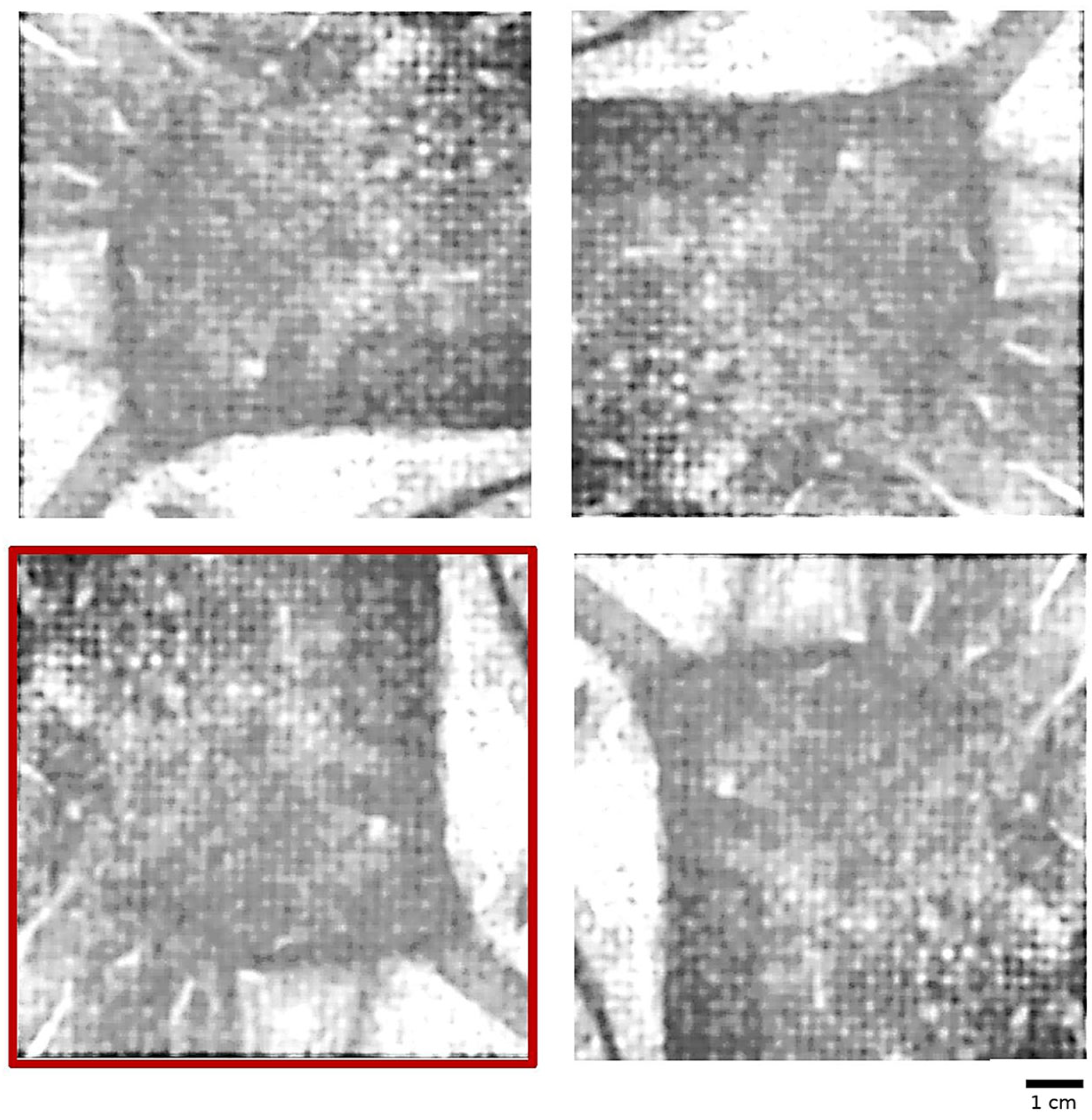
When the radiograph is rotated by 180° (Figure 1) and viewed in inverted grayscale (Supplementary Figure S1), a coherent structural armature emerges (cranial arc, facial axis, and shoulder/torso plane). These forms remain stable under small tonal changes and minor angular adjustments, supporting an interpretation of orientation-dependent structure rather than random density variation. Comparable rotation-dependent understructures have been reported in technical studies of Picasso’s reused supports [1,2,17].

3.1.2. Curvilinear Planning Contours

Across adjacent crops, a long continuous curvilinear boundary persists and withstands grayscale inversion. Shorter luminous edits terminate against this main seam in a mechanically sensible manner, consistent with intentional base-layer planning rather than incidental texture [16,17], Supplementary Figure S2.

3.1.3. Rotated Support Logic

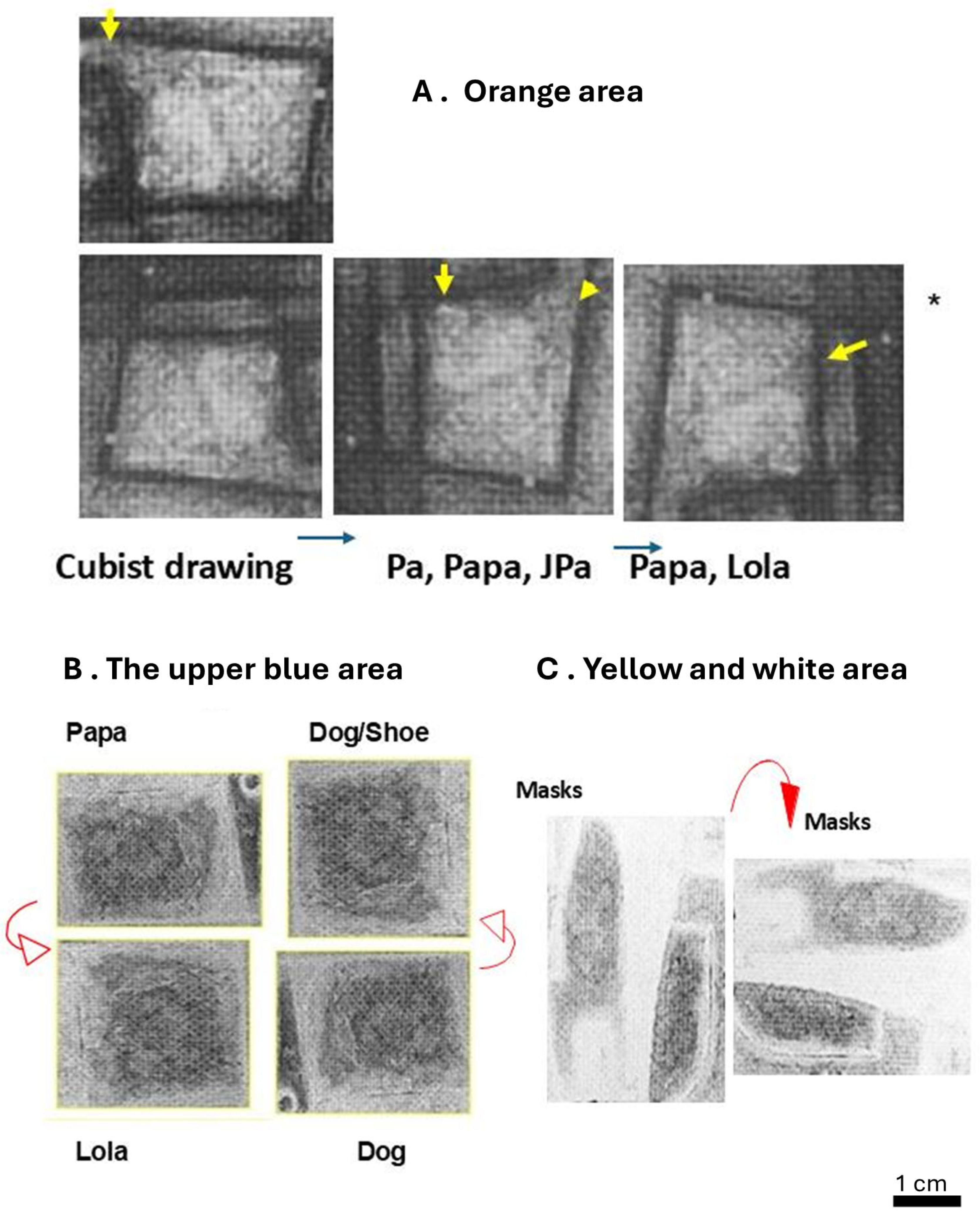
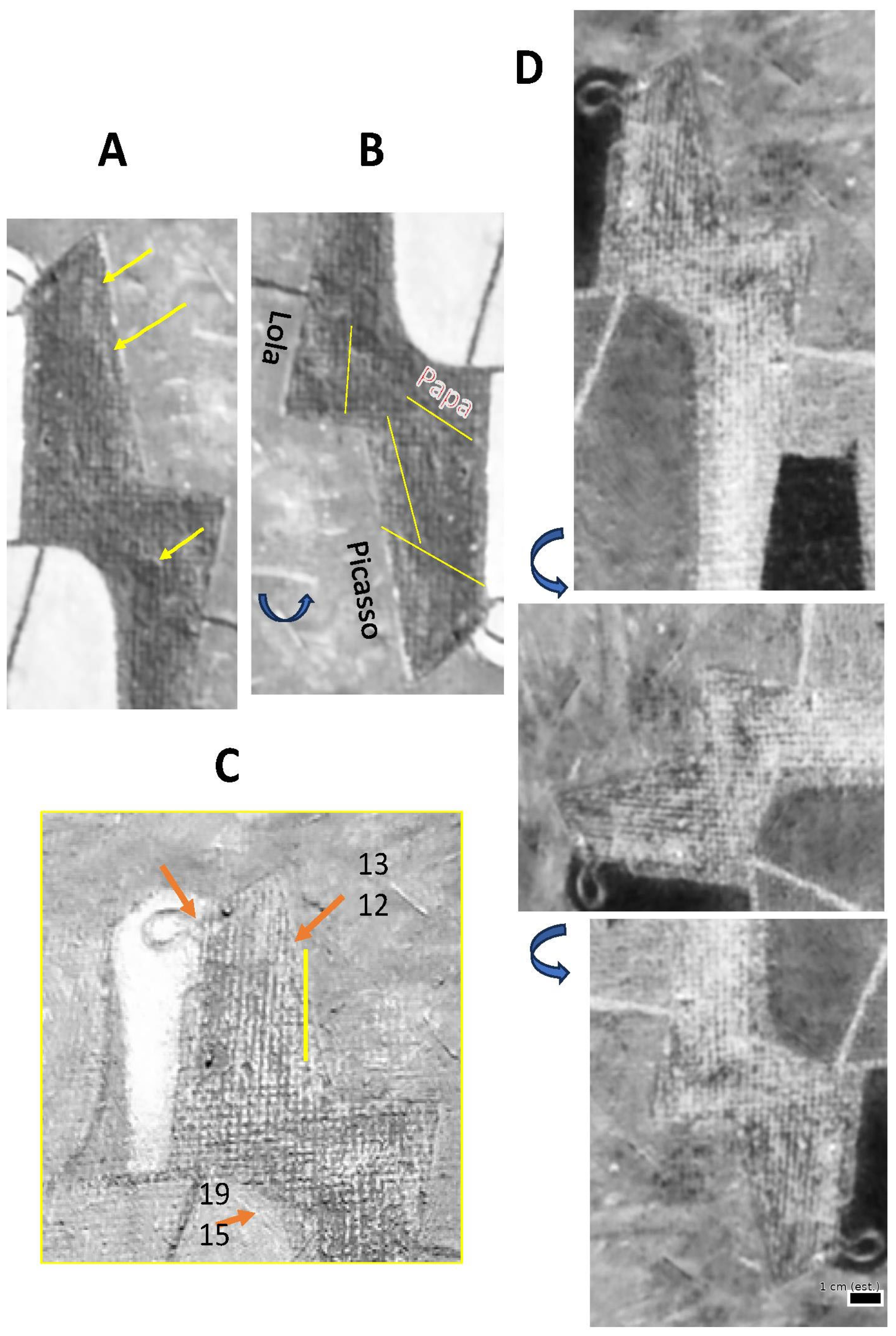
In mapped zones A, B and C in Figure 2, dominance flips between edge families as the image rotates or polarity inverts, while long boundaries remain continuous. This behavior documents reused and reoriented support [1,2], consistent with documented practice in Picasso’s working methods [16,20].

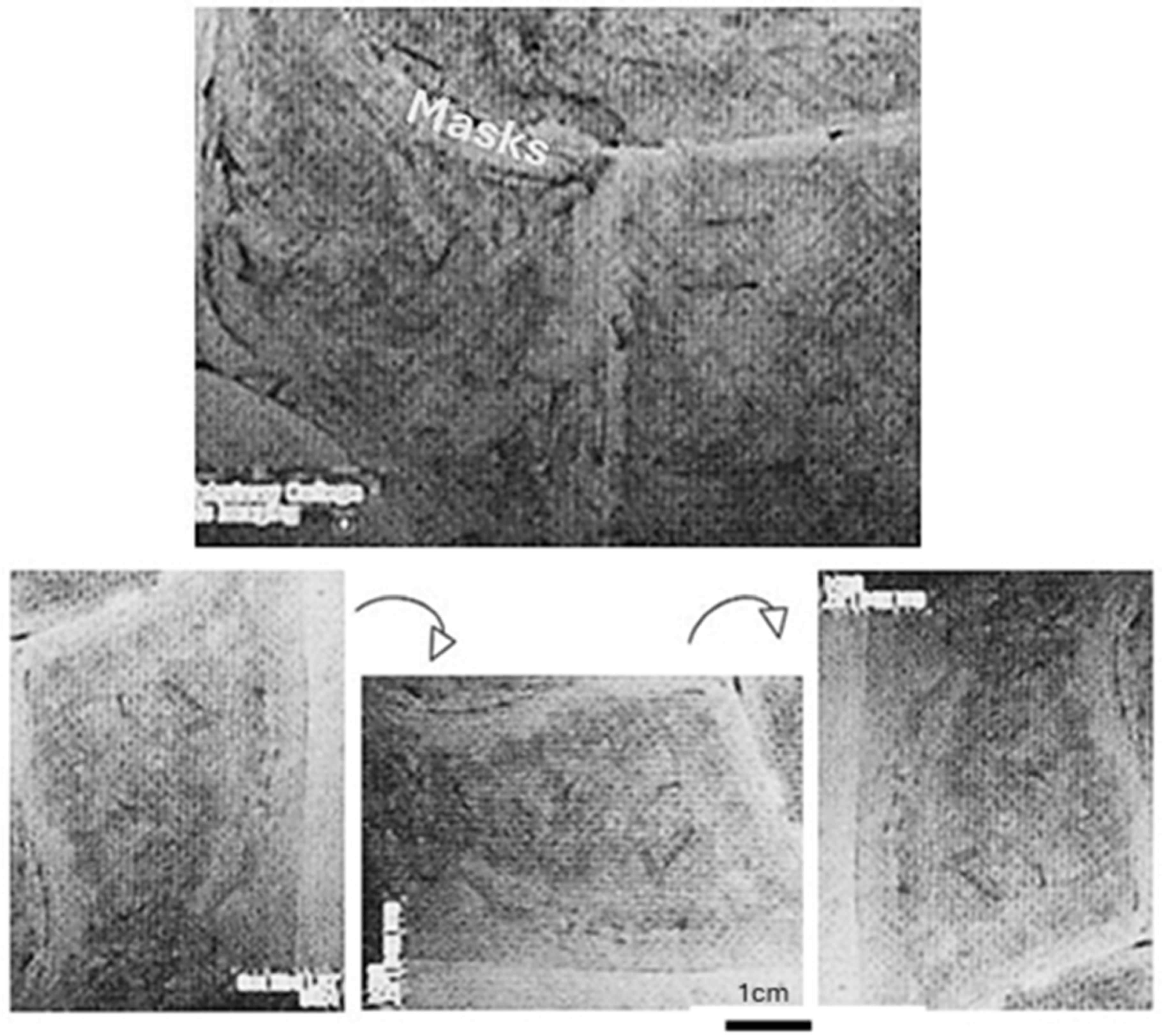
3.1.4. Base-Layer Guide and Cross-Modal Concordance

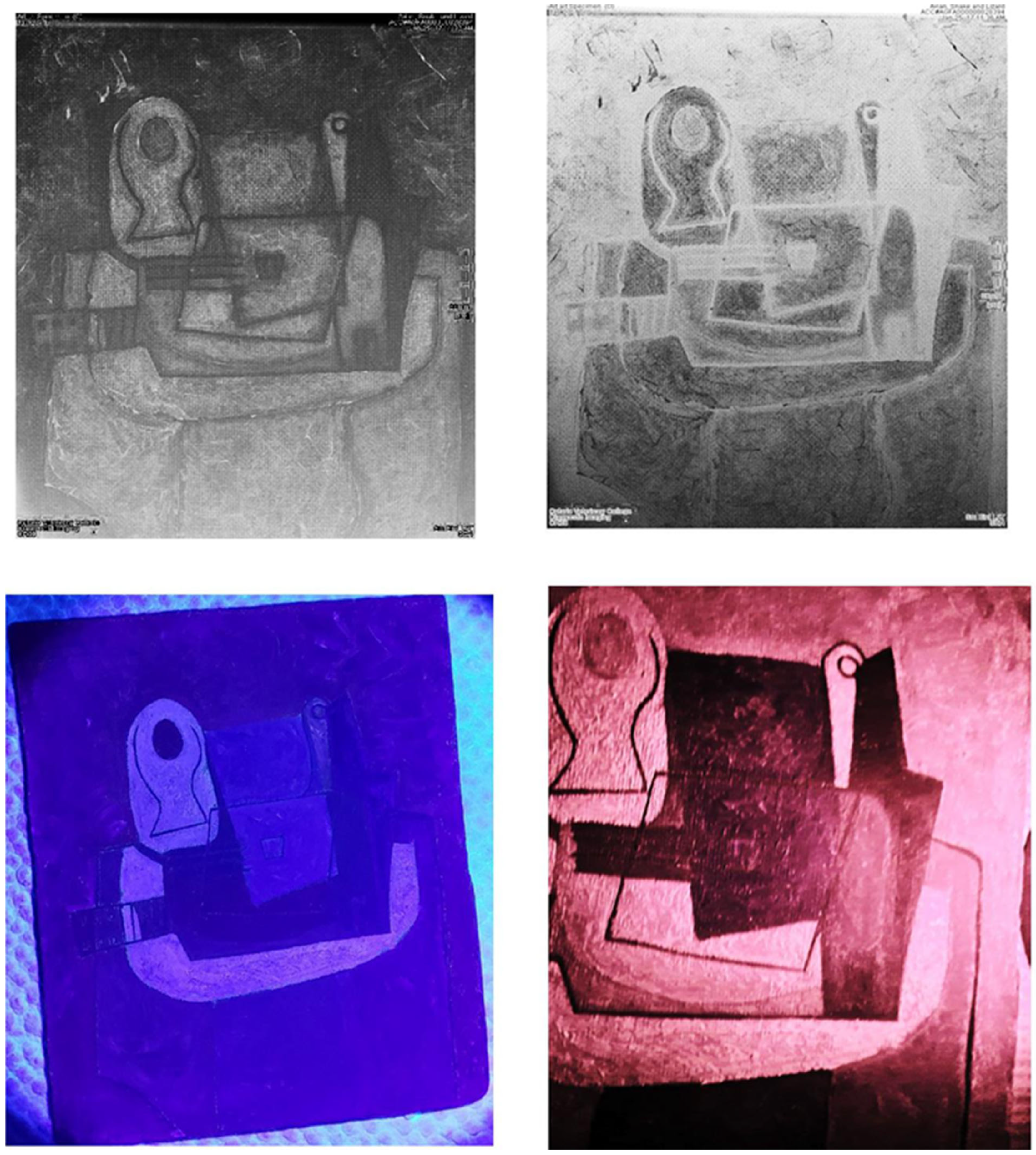
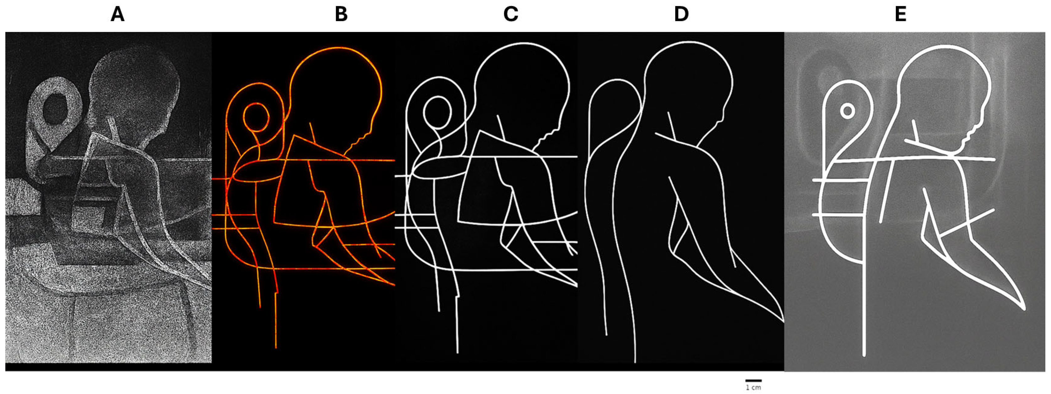
In the “Masks & Harlequins” area, a primary seam separating painted domains persists across polarity states while secondary edges terminate sensibly against it (Figure 3). Orientation mapping (Supplementary Figure S3) reproduces the gain/loss of edge prominence without loss of geometric continuity, supporting interpretation as a base layer guide refined through later revisions. At a shared locus, X-ray seams co-locate with UV-visible fluorescence features and corresponding deep-red undermarks, demonstrating depth–surface alignment (Figure 4). The associated glyphs and date numerals confirmed across visible, deep-red, and raking-light views are documented in Figure 5, Figure 6 and Figure 7, reinforcing that these surface inscriptions participate in the same constructional logic [17,18]. A global inverted radiograph (Supplementary Figure S4) further shows a continuous spine-like contour traversing multiple domains with local edge thickening at junctions, consistent with multi-stage construction.

3.1.5. Workflow Confirmation of Rotation-Dependent Structure

To make the interpretation pathway explicit, we present a five-panel diagnostic workflow that proceeds from the raw radiograph to a heatmap of refindable boundaries, to a contour overlay demonstrating hierarchical terminations, and finally to an interpreted silhouette (Figure 5). The same long planning seam that remains legible under rotation and grayscale inversion anchors in each stage demonstrate continuity and mechanical coherence from raw data to reconstruction. This presentation complements the rotated/inverted armature in Figure 1 and Figure S1 and the global seam continuity emphasized in Supplementary Figure S4. Figure 5 illustrates the derivation, synthesis, and internal validation of a structural armature from subsurface constraints. The reconstruction yields a coherent composite geometry (Figure 5D) derived solely from admitted subsurface constraints because these constraints exhibit internally consistent spatial organization. This body-centered organization of the underlying construction system is consistent with Cubist practices in which figuration persists at the level of structure even as surface representation is fragmented.

3.1.6. X-Ray Pentimenti and X-Ray Difference Map

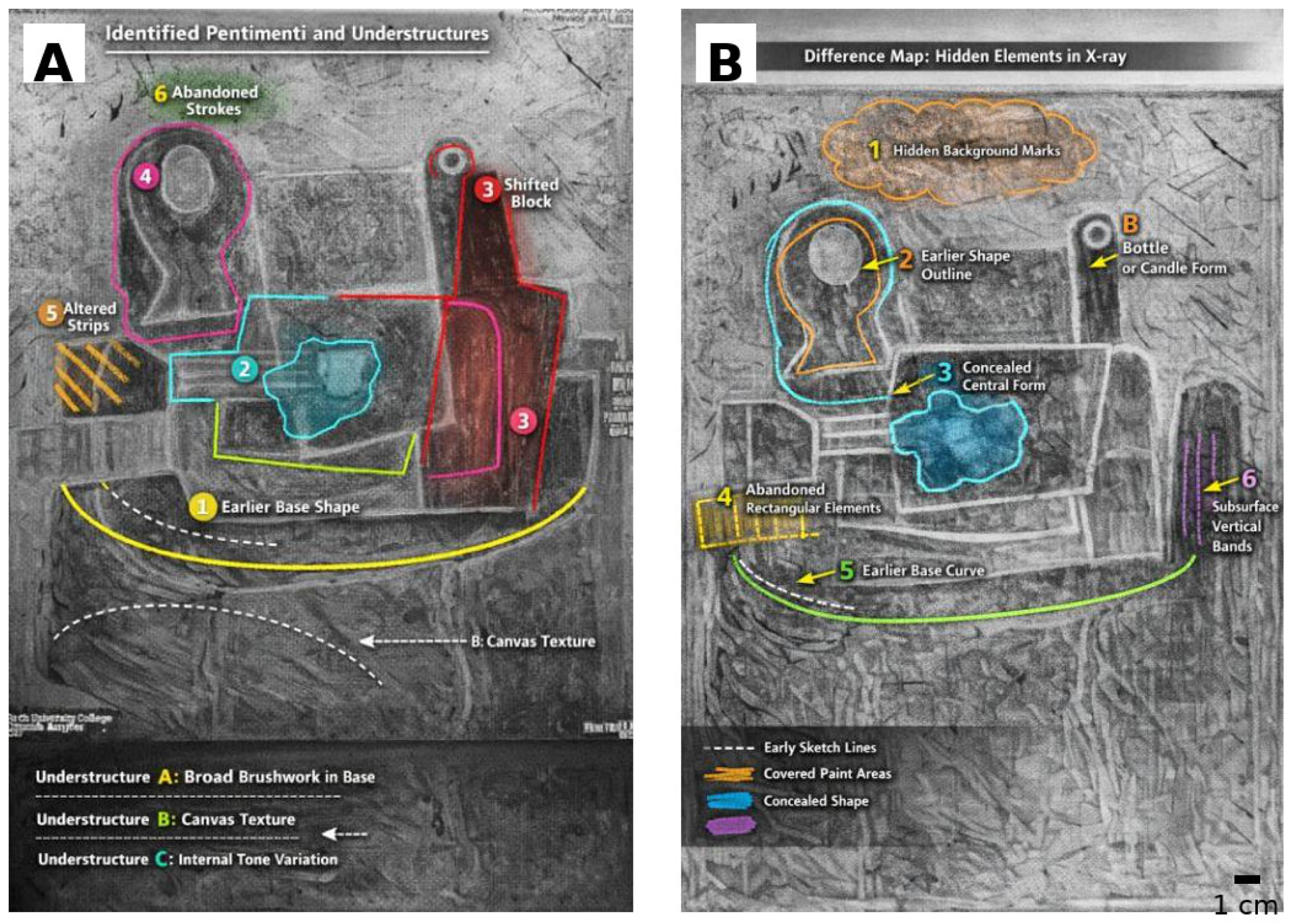
The principal pentimenti detected in radiography include (1) an earlier, broader base curve later tightened and raised, (2) a concealed rounded form within the central block, (3) a shifted right vertical block, (4) redrawn inner/outer contours in the upper-left rounded form, (5) earlier oblique strips at left replaced by a horizontal element and (6) abandoned background strokes (Figure 6A). The difference map shows hidden elements, not present in surface configuration: hidden background marks, earlier outline, concealed central form, abandoned rectangular elements, earlier base curve, and subsurface vertical bands (Figure 6B).

3.2. Visible-Light Corpus: Surface Inscriptions, Relief, and Stratigraphy

3.2.1. Names and Letterforms

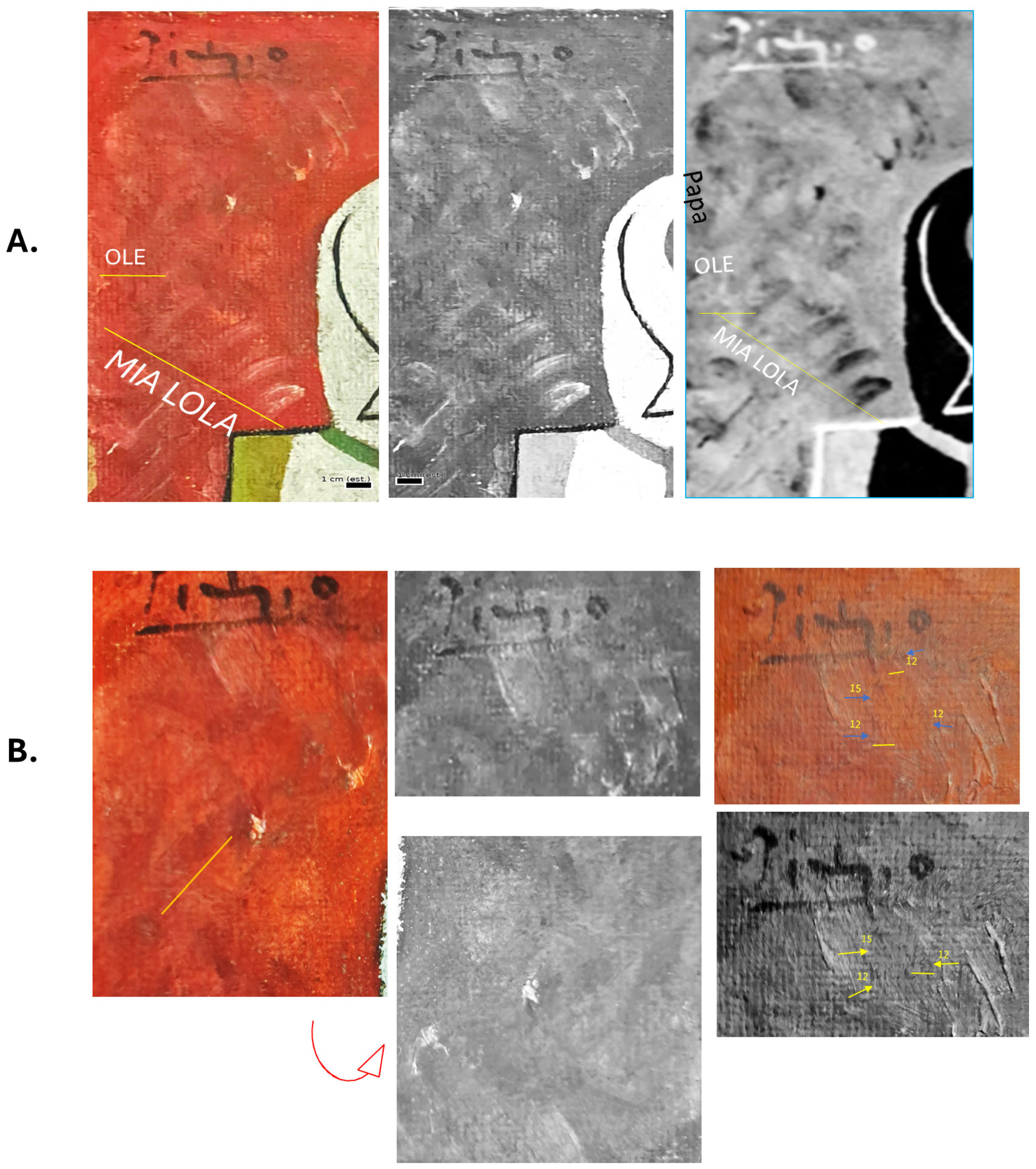
Full-field and enlarged color views show letterforms “Ole Mia LOLA” and “DOLORES” without spectral manipulation. Stroke mechanics are consistent across loci, and raking light reveals micro-relief with paint settling within grooves. Several areas show later paint, bridging earlier incisions, establishing a sequence in which inscriptions precede overpainting (Figure 7).

3.2.2. Context Inscription and Numerals Across Fields

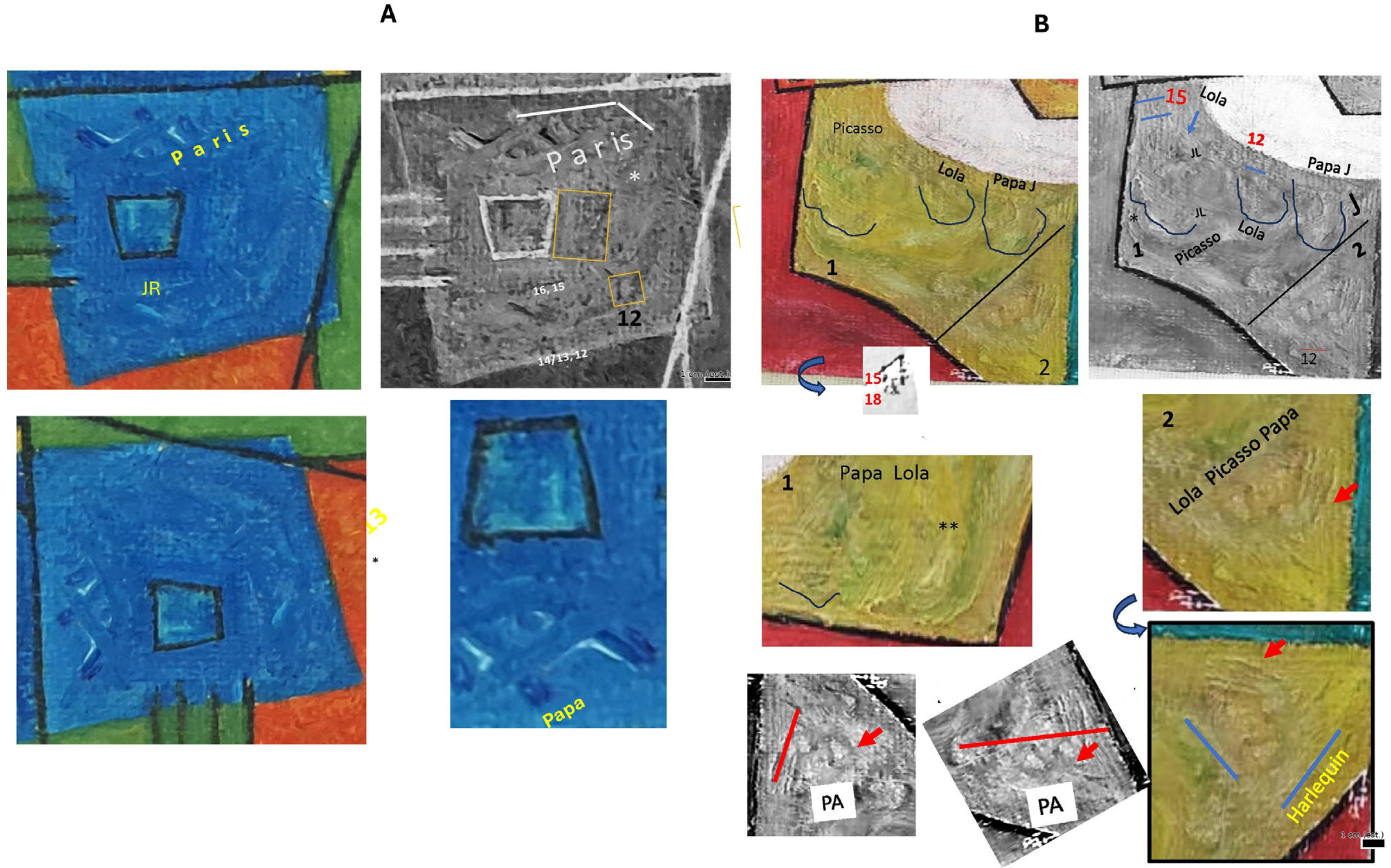
The word “PARIS” is readable in visible-light imaging within the lower blue band and appears with nearby numeral clusters. Year numerals (12, 13, 15, 18, 19, 21) are visible across blue and yellow fields and under the ranked light in the black area. The numbers show partial burial and stroke-order behavior consistent with early execution and later layering (Figure 8A,B and Figure 9B).
Raking reflected light views reveal incised strokes and later paint riding over engraved marks, establishing execution order and confirming contemporaneous inscription. Matched black-white and inverted raking views document micro-relief, incision depth, and paint displacement. Distributed numerals and contextual glyphs appear across multiple fields (Figure 9B,C).

3.2.3. Macro Topography and Ligatures

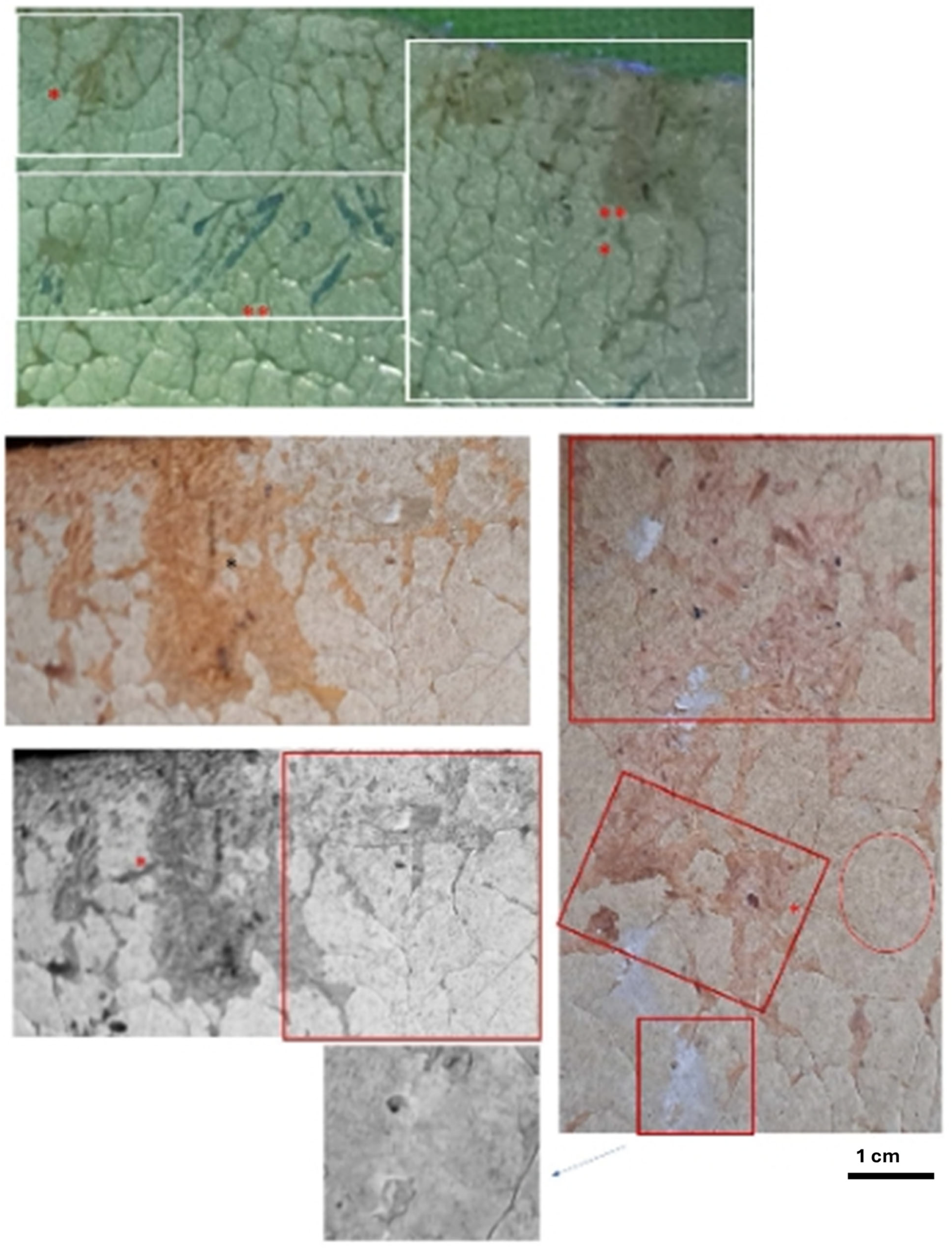
Side-lit macros document incision depth, paint displacement, and localized ink reinforcement forming ligature-like structures (e.g., J/JPL + La) (Figure 10). Such deliberately modified surfaces are consistent with documented non-traditional interventions and support manipulation in Picasso’s practice.

3.2.4. Reduced-Color and Grayscale Confirmation

Letterforms and numerals persist through reduced-color, grayscale, and inverted-grayscale checks, indicating that legibility derives from luminance and relief rather than chromatic coincidence. These transformations serve as confirmatory controls and mitigate pareidolia concerns (Supplementary Figure S5).

3.3. High-Magnification Micro-Relief Motifs in the Tuner-Area Quadrants

High-magnification imaging reveals recurrent, mechanically consistent micro-relief features across multiple loci. Repeated morphology and bounded spatial placement suggest intentional surface manipulation without implying statistical replication or iconographic interpretation. These observations satisfy admissibility and anti-pareidolia controls defined in Supplementary Method S1. These observations are presented as physical surface phenomena and are not interpreted as symbolic, figurative, or iconographic content.
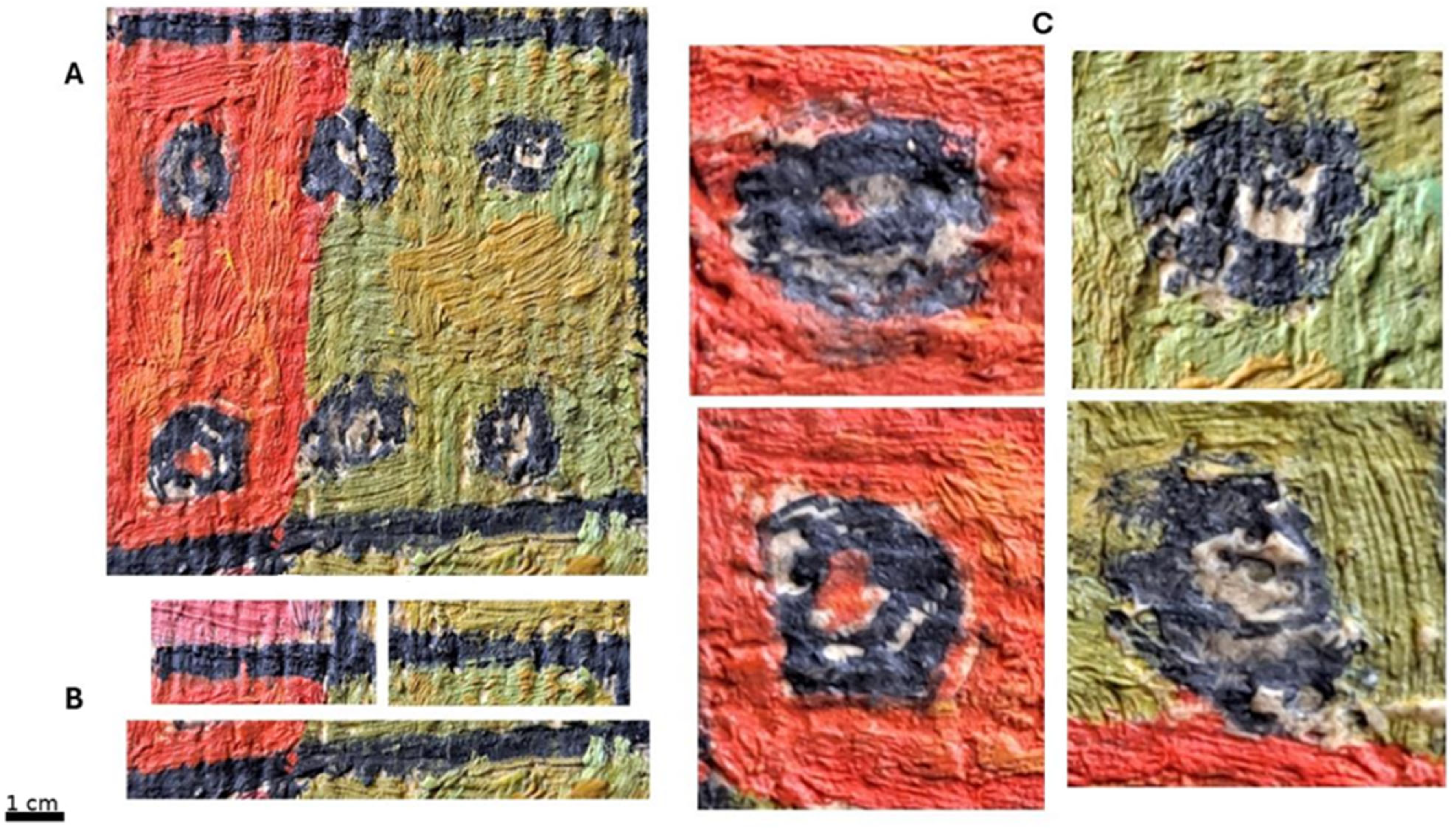
High-magnification imaging of the six tuner-area quadrants (Figure 11) reveals a set of recurring micro relief motifs that contribute an additional layer of process-based evidence for deliberate surface modification. These features, compact circular and semi-circular forms, internally partitioned structures, and discrete pigment reservoirs, are visible across red, green, and transitional color fields. Their legibility persists under full-color, reduced-color, and grayscale transformations, indicating that they are carried by surface relief and luminance rather than color dependence. This behavior aligns with the anti-pareidolia criteria defined in Section 2.3 and reinforces that the motifs are physically present micro-structures rather than chromatic coincidence. Across the six tuner quadrants, the motifs share consistent mechanical behavior. Raking-light and side-lit views show shallow incisions and localized paint displacement surrounding the motifs, with pigment accumulation in recessed micro-basins. In several loci, convex paint-ridges border the motifs, suggesting intentional manipulation of wet or semi-set paint. This morphology of recessed centers with peripheral displacement is consistent with deliberate micro-relief shaping rather than incidental canvas texture or casual brushwork. The repeated appearance of similarly proportioned structures is consistent with repeated, mechanically similar surface interventions. Spatially, these motifs occupy bounded compositional cells defined by the tuner elements, a region already implicated in multi-stage construction from both X-ray and visible-light evidence. Their distribution within these compartments suggests that they were integrated during a specific campaign of surface intervention rather than accumulated over unrelated painting sessions.
Micro-relief continuity within each quadrant, combined with recurrent internal partitioning, points to an intentional patterning system. Although not interpreted here as iconographic or figurative content, the internal coherence, repetition, and structural persistence of these motifs satisfy continuity, polarity robustness, and refindability criteria defined for admissible features (Section 2.1, Section 2.2, Section 2.3 and Section 2.4). Together, the high-magnification motifs extend the surface-based evidence presented in Section 3.2 by demonstrating an additional tier of deliberate micro-relief modification embedded within the tuner-area construction. Their persistence under luminance-based transformations, mechanical coherence across loci, and bounded spatial organization indicate purposeful creation consistent with the broader multi-campaign, rotation-aware working process documented throughout this study. This micro-scale structural evidence further supports unified constructional logic and adds to a cumulative technical footprint that would be difficult to reproduce without sustained, process-level intervention.

4. Discussion

This study assesses whether the imaging results demonstrate an internally coherent, reproducible constructional logic consistent with Picasso’s working practices between 1906 and 1921. It asks whether subsurface structures (radiography) and surface or near-surface features (visible, raking-light, UV/deep-red) can be explained by a mechanically plausible sequence of planning, incision, and subsequent revisions. The approach is strictly process-based. It relies on features that persist under rotation and polarity stress tests, exhibit hierarchical seam behavior, show stratigraphic precedence of incisions, and maintain cross-modal co-location. Critically, strength derives not from any isolated motif or inscription but from the convergence of independent technical observations that remain stable across these transformations. Interpretations were admitted only when features survived continuity, polarity, rotation, and refindability stress-tests across independent modalities, providing a formal safeguard against pareidolia.

4.1. Orientation-Dependent Construction as a Robust Process Marker

A defining characteristic of the radiography dataset is its orientation-dependent coherence: subsurface structures that become geometrically intelligible only after rotation that remain stable under grayscale inversion. In the radiograph in Figure 1 and Figure S1, a coherent armature, comprising a cranial arc, facial axis, and shoulder/torso plane, emerges clearly at 180° rotation and persists in inverted grayscale views. Longer boundaries also maintain continuity, even as local edge families gain or lose prominence with rotation (Figure 2 and Figure S3). Such refindable, rotation-sensitive legibility is difficult to reconcile with random density variation, which typically fragments or changes identity under these stress conditions. The diagnostic workflow shows that orientation-dependent coherence is not a post hoc drawing but a property that survives each admissibility criteria (Supplementary Method S1: continuity across crops, polarity robustness, hierarchical terminations, and refindability after rotation) before yielding an anatomically coherent armature. Orientation-dependent examination in Figure 5 reveals a coherent subsurface armature that informs the painting’s constructive logic. In Cubist practice, figuration was often relocated from surface depiction to structural organization, with figures treated as armatures of axes, masses, and curvilinear constraints rather than complete representations. Fragmentation of appearance did not abandon the figure but reconfigured it as an underlying framework guiding development. The reconstructed armature in Figure 5 persists across rotations and revision cycles, indicating a stable, body-centered geometry. The overlay in Figure 5E demonstrates that the silhouette is grounded in the admitted subsurface contours isolated in Figure 5C, indicating that constructive constraints can give rise to coherent composite geometry. The pentimenti maps in Figure 6A highlight structures that remain geometrically intelligible only after rotation and persist under grayscale inversion. This visual consolidation clarifies rotation-sensitive behavior by identifying the specific boundaries that retain identity across orientation tests. Thus, the diagnostic workflow in Figure 5 and the pentimenti maps in Figure 6A link the rotated/inverted structures of Figure 1 to the consolidated maps in Figure 6B and preempt interpretive ambiguity.
The demonstrated persistence of the same structural relationships across these five admissibility criteria supports deliberate planning on a reused [1,2] and reoriented support rather than incidental texture. These findings align with published technical studies of Picasso’s working methods (Favero et al., 2017; Pouyet et al., 2020; Delaney et al., 2010) [16,17,18]. Comparable cross-modal analyses in La Miséreuse accroupie (Langley et al., 2013; Barten & Delaney 2018) [1,2] and Harlequin Musician likewise distinguished deliberate planning from coincidental density patterns [17,18]. These precedents reinforce the interpretation of rotation-dependent legibility as a high-value process marker that is not easily emulated superficially.

4.2. Base-Layer Planning, Seam Hierarchy, Cross-Modal Concordance, and Revision Cycles

Across the radiographs, planning exhibits a primary-secondary hierarchy where long, continuous boundaries separate major domains while shorter edits terminate cleanly against them in mechanically sensible ways. This is consistent with a base-layer guide that was refined through successive revision cycles rather than a single-pass execution. Importantly, these seams do not behave like incidental board texture or compositional ‘noise’; they persist through grayscale inversion and can be re-found after rotation without loss of geometric identity (Figure 3 and Figure S2). The earlier base curve, concealed central form, and shifted right block (Figure 6A) constitute a coherent revision cycle, confirming a base-layer guide refined through later campaigns. The difference map in Figure 6B isolates hidden elements that are absent from the surface configuration, providing a complementary view of covered forms and subsurface bands.
Visible- and raking-light imaging provides complementary stratigraphic evidence at the surface (Figure 7, Figure 8 and Figure 9). Incised inscriptions and numerals are physically embedded in the paint structure, where later paint partially fills grooves and, in several loci, bridges over incision edges. This establishes a clear sequence in which incision/inscription precedes at least one subsequent overpaint campaign. When these observations are considered alongside the X-ray seam hierarchy, depth and surface evidence converge on a single construction logic unfolding over multiple campaigns. Cross-modal registration (X-ray/UV/deep-red co-location in Figure 4) further strengthens this interpretation by showing that independently acquired datasets co-locate at multiple loci. Subsurface seams detected in X-ray correspond spatially with IR-visible undermarks and with UV active interventions, and they align with stable visible landmarks (contour breaks, junctions, and structural geometries). Such depth–surface concordance is difficult to reconcile with staged additions executed at unrelated times by different hands; instead, it supports a unified working process in which planning and subsequent revisions remained constrained by the same underlying geometry.

4.3. Comparative and Historical Context: Why the Inscriptions Matter

Comparative context is best introduced after the technical findings are established, because the present approach is process-based rather than stylistic. Within that boundary, the inscriptions provide a historically coherent context: the painting contains physically incised names and place references (e.g., “LOLA,” “DOLORES,” “PARIS”) and distributed numerals that are integrated into the paint film rather than written as later, surface-only annotations. Picasso’s broader practice includes embedding letters, names, dates, and place references as compositional elements rather than as post hoc labels, and the stratigraphic integration observed here is compatible with that working milieu. At the same time, inscriptions and perceived motifs are not treated as handwriting attribution or iconographic proof. Their evidentiary value in this study is mechanical and stratigraphic. They are physically present, they follow plausible stroke mechanics and relief behavior, they persist across imaging conditions (including reduced-color and polarity/grayscale checks), and they participate in the same constructional system that governs the subsurface seams. This bounded use of context anchors interpretation in historically plausible practice while avoiding overreach from purely stylistic parallels.
Across the X-ray corpus, planning seams exhibit a primary–secondary hierarchy. Long, continuous boundaries partition major painted domains while shorter, localized edits terminate cleanly against them in mechanically sensible ways. This behavior, visible, for example, in the curvilinear planning seam and its subordinate terminations in Figure 3 and Figure S2, is consistent with a base-layer guide that structured later adjustments rather than a single-pass execution. The stability of these seams under grayscale inversion and their refindability after rotation further support their interpretation as intentional planning structures. Surface and near-surface imaging provide complementary stratigraphic evidence for multi-stage construction. Incised inscriptions and numerals are physically embedded in the paint structure: raking-light views show grooves with later paint partially filling them and, in some loci, bridging over incision edges (Figure 7, Figure 8 and Figure 9). This establishes a clear execution order in which incision/inscription precedes at least one subsequent overpaint campaign, aligning with the radiographic evidence for iterative revision cycles. Crucially, cross-modal registration indicates that depth and surface features are governed by the same geometric system. Subsurface seams detected in radiography co-locate with UV-active interventions and corresponding deep-red/visible undermarks at shared loci (Figure 4), and the registration is supported by stable landmarks (junctions, contour breaks, and structural geometries). Such depth–surface concordance is difficult to explain by staged additions executed at unrelated times; instead, it supports a unified working process in which planning, inscription, and later revisions remained constrained by the same underlying construction.

4.4. Multiyear Chronology and Embedded Context: A Palimpsest Model

The distribution of year numerals spanning 1912–1919 across multiple color fields, together with the final dated signature (9 April 1921), is consistent with a palimpsest chronology in which earlier inscriptions were retained and subsequently overpainted or partially buried during later campaigns. The critical observation is not merely that numerals are present, but that they are physically integrated into the stratigraphy: raking-light relief and partial burial indicate execution prior to later paint deposition (Figure 8 and Figure 9). The same stratigraphic logic is evident in lettered inscriptions where later paint bridges earlier grooves (Figure 7). This multi-campaign behavior aligns with the broader technical picture of rotation-aware planning and iterative revision: subsurface structures indicate reuse/reorientation (Figure 1 and Figure 2), while surface stratigraphy records the temporal ordering of interventions (Figure 7, Figure 8 and Figure 9). Together, these datasets support an extended construction history rather than a single, closed execution event. Such multi-campaign behavior is compatible with documented revision histories in Picasso’s practice, particularly in contexts where supports are reused and compositions are repeatedly adjusted.

4.5. Materials Plausibility and Deliberately Modified Surfaces

The surface record includes deliberately modified micro-relief incisions, displaced paint ridges, localized ink reinforcement, and ligature-like marks, whose visibility persists under reduced-color and grayscale controls (Figure 9 and Figure 10). Macro documentation further shows localized reinforcement and relief behavior that is consistent with purposeful manipulation of wet or semi-set paint (Figure 11). At higher magnification, recurrent micro-relief motifs in tuner-area quadrants exhibit consistent morphology and bounded placement (Figure 11), supporting a reproducible intervention rather than stochastic canvas texture. These behaviors also remain compatible with the previously reported materials (Sessa et al., 2016; Fuster-López et al., 2020) [8,9] context for the painting, which identified period-consistent pigments and media and documented localized later refurbishment confined to a restricted zone (Bakovic et al., 2022) [10]. Within that constraint-based framework, the heterogeneous paint-film behavior and relief phenomena are more consistent with iterative, non-traditional working methods, and natural complex stratigraphy than with post hoc fabrication of a ‘look.’ Importantly, the present conclusions do not depend on destructive sampling: they arise from reproducible imaging observations and the mechanically coherent way those observations integrate across scales (Figure 10 and Figure 11) and across modalities (Figure 4).

4.6. Attributional Significance and Counter-Forgery Considerations

From a counter-forgery perspective, the strength of the evidence lies in converging constraints rather than in any single feature. The co-occurrence of (i) rotation-dependent subsurface coherence that survives grayscale inversion (Figure 1 and Figure S1), (ii) rotation-stable seam architecture with primary–secondary hierarchy (Figure 3 and Figure S2), (iii) physically incised inscriptions and numerals with demonstrable stratigraphic precedence (Figure 7, Figure 8 and Figure 9), and (iv) cross-modal co-location linking depth seams to UV/deep-red/visible features (Figure 4) constitutes a process-based fingerprint that is difficult to stage convincingly. Accordingly, this study does not claim attribution on stylistic grounds alone. Rather, it shows that the painting’s internal constructional logic is coherent, reproducible, and mechanically plausible within the documented technical repertoire of the relevant period, thereby strengthening an originality-positive interpretation when considered alongside provenance and curatorial evaluation. Future work can remain non-destructive; optional elemental mapping (e.g., macro-XRF) could refine relationships among painted domains and planning seams, but it is not required for the principal conclusion that multiple independent modalities converge on a unified, multi-campaign, orientation-aware working process.

4.7. Previously Unreported Process Markers and Why They Matter

This study identifies four interacting process markers that, taken together, clarify aspects of Picasso’s construction workflow not previously formalized within a single, non-destructive protocol.
(1)
Orientation-dependent armature: X-ray structures become geometrically coherent only after controlled rotation and remain stable under inverted grayscale viewing; this operationalizes rotation as a diagnostic stress test, distinguishing intentional planning from incidental density variation (Figure 5; Supplementary Method S1). This extends prior technical studies that documented underdrawings and hidden compositions by adding a formal rotation-mapping criterion to discriminate planning structures, complementing work on La Miséreuse accroupie (Langley et al., 2013; Barten & Delaney 2018) [1,2] and related Cubist/Blue Period (Casadio 2010; Gedo 1986) [13,14] analyses (Favero et al., 2017; Pouyet et al., 2020; Bakovic et al., 2022) [10,16,17].
(2)
Hierarchical seam architecture: a primary base-layer seam governs later edits that terminate mechanically against it, and this geometry retains identity across rotations and modalities; the result is an explicit, reproducible map of planning hierarchy rather than an inferred one (Figure 2 and Figure 3; Supplementary Method S1). This codifies a seam-hierarchy framework that aligns with Picasso’s iterative revisions on reused supports (Langley et al., 2013; Barten & Delaney 2018) [1,2] while making the planning logic explicit through cross-modal overlays, thereby systematizing observations scattered in earlier technical overviews (Arslanoglu et al., 2013) [4].
(3)
Stratigraphically embedded writing: incised names, place, and distributed year numerals (1912–1919) are earlier than overlying paint, verified by groove filling/bridging and persistence under grayscale and grayscale inversion, thereby constraining a multi-year palimpsest culminating in the 1921 signature and reframing text as a constructional act (Figure 7, Figure 8 and Figure 9). This reframes textual elements from surface annotation to process-integrated construction, consolidating earlier observations about Picasso’s use of letters and numerals within composition by grounding them in stratigraphy and relief tests (Delaney et al., 2010; Jiménez, 2021) [12,18].
(4)
Microscale relief motifs: repeated circular/semi-circular relief forms and pigment reservoirs in tuner-area quadrants evidence deliberate manipulation of semi-wet paint, adding a micro-tier of process control that extends beyond typical accounts of revision or support reuse (Figure 11). This introduces a reproducible microscale relief tier, rarely isolated as a procedural marker in Picasso’s technical literature, thereby broadening the toolkit beyond macro-level pentimenti and material IDs.
Taken together, these four markers form a non-destructive, reproducible process signature that integrates rotation awareness, seam hierarchy, stratigraphic text anchoring, and microscale relief into a single analytical framework, extending earlier technical insights on reused supports and concealed compositions with an auditable protocol.

5. Conclusions

Using only non-destructive imaging, we reconstruct a unified, multi-campaign workflow for the painting: a rotation-sensitive base plan (X-ray) organizes later edits; incised textual elements predate overpaint and anchor a 1912–1919 palimpsest that resolves with the 1921 signature; and recurrent microscale relief features record intentional surface shaping during semi-wet stages. Cross-modal co-location shows that depth and surface obey the same geometric constraints, indicating that planning, inscription, and revision were not independent additions but components of one evolving construction system. These findings contribute to the technical understanding of Picasso-period working methods by formalizing orientation mapping and seam hierarchy, demonstrating stratigraphically embedded writing as part of construction, and introducing microscale relief as a reproducible marker of process. The resulting technical footprint is mechanically coherent and difficult to fabricate, supporting an originality-positive interpretation when considered alongside the materials context and curatorial review. These findings do not constitute stylistic attribution but demonstrate that the painting’s internal constructional logic is mechanically coherent and historically plausible within the documented technical repertoire of the period.

Supplementary Materials

The following supporting information can be downloaded at: https://www.mdpi.com/article/10.3390/heritage9040135/s1. Figure S1. Inverted-polarity X-radiograph used for orientation comparison. Inverted-grayscale rendering of the full X-radiograph used to visually examine subsurface density relationships under polarity reversal. The image is shown at native detector resolution. Polarity inversion and linear brightness/contrast adjustment were applied uniformly to the entire image for visualization purposes only. No resampling, filtering, segmentation, or feature enhancement was performed. The figure is provided to allow comparison with the non-inverted radiograph discussed in the main text. Figure S2. Curvilinear subsurface boundary examined under polarity and rotation. X-radiographic crop showing a continuous curvilinear subsurface boundary across regions of varying tonal density. The same data are viewed under polarity inversion and rigid rotation to assess visual persistence of boundary geometry. All transformations are global, linear operations applied without resampling. The figure illustrates refindability of the same boundary under controlled visualization changes and does not constitute quantitative image analysis. Figure S3. Orientation-mapping sequence of a single radiographic region. Sequential rigid rotations (0°, 90°, 180°, 270°) of the same X-radiographic region shown at identical scale and resolution. Local edge contrast varies with orientation; however, spatial relationships among major subsurface features remain visually stable. The sequence is provided to document orientation-dependent visibility effects under controlled rotation only. No new features are introduced by these transformations. Figure S4. Global radiograph and interpretive tracing of a continuous subsurface boundary. (A) Inverted-grayscale radiograph showing the global subsurface structure. (B) The same image with a manually traced continuous boundary overlaid to assist visual inspection. The tracing is interpretive and derived entirely from features visible in the radiograph. It does not represent automated segmentation or analytical extraction and is included solely as an illustrative aid to show spatial continuity across domains. Figure S5. Visualization controls for inscription legibility. Four visualization renderings of the same visible-light image: (A) color, (B) reduced-color, (C) grayscale, and (D) inverted grayscale. Reduced-color was generated by a single global chromatic saturation reduction applied uniformly to the entire image. Grayscale and inversion are standard linear transformations. These renderings do not constitute independent imaging modalities and are included as visualization controls to assess whether legibility depends on hue rather than luminance and surface relief. Supplementary Methods—Appendix A: Supplementary Radiography Method S1: Procedural Guide for ‘’Orientation Mapping, Admissibility Criteria, and Anti-Pareidolia Control; Supplementary Method S2: ImageJ Workflow for Radiographic Pentimenti and Difference Visualization; Supplementary Methods S3: ImageJ Workflow for Diagnostic Reconstruction. Appendix B: Full-resolution figures.

Author Contributions

Conceptualization, Methodology, Investigation, Data Curation, M.B.; Visualization, M.B.; Writing—original draft, M.B.; Writing, review & editing, M.B. and A.P.-M. All authors have read and agreed to the published version of the manuscript.

Funding

This research received no external funding.

Data Availability Statement

All imaging crops, polarity states, rotation mappings, and derived overlay files are available from the corresponding author on reasonable request.

Conflicts of Interest

The authors declare no conflicts of interest.

References

  1. Langley, A.; Muir, K.; Bezur, A. Looking Below the Surface of Picasso’s The Old Guitarist. In Painting Techniques, History, Materials and Studio Practice; Wallert, A., Ed.; University of Leiden: Amsterdam, The Netherlands, 2013; pp. 258–263. [Google Scholar]
  2. Barten, J.; Delaney, J.K. Pablo Picasso’s Woman Ironing, and the Portrait Hidden Beneath. In Thannhauser Collection: French Modernism at the Guggenheim; Fontanella, M.M., Ed.; Guggenheim Museum: New York, NY, USA, 2018; pp. 151–155. [Google Scholar]
  3. Golding, J. Cubism: A History and an Analysis, 1907–1914, 3rd ed.; Belknap Press: Cambridge, MA, USA, 1988. [Google Scholar]
  4. Arslanoglu, J.; Centeno, S.A.; Digney-Peer, S.; Duvernois, I. Picasso in The Metropolitan Museum of Art: An Investigation of Materials and Techniques. J. Am. Inst. Conserv. 2013, 52, 184–201. [Google Scholar] [CrossRef] [Scilit]
  5. Umland, A.; Hartzell, B.; Gerson, S. Picasso: The Making of Cubism 1912–1914; Metropolitan Museum of Art: New York, NY, USA, 2014. [Google Scholar]
  6. Tinterow, G.; Stein, S.A. Picasso in the Metropolitan Museum of Art; Metropolitan Museum of Art: New York, NY, USA, 2010; pp. 57–59. [Google Scholar]
  7. Musée National Picasso–Paris. Guitare. Available online: https://www.museepicassoparis.fr/fr/guitare (accessed on 5 February 2025).
  8. Sessa, C.; Jiménez de Garnica, R.; Rosi, F.; Fontana, R.; Garcia, J.F. A Study of Picasso’s Painting Materials and Techniques in Six of His Early Portraits. J. Am. Inst. Conserv. 2016, 55, 198–216. [Google Scholar] [CrossRef] [Scilit]
  9. Fuster-López, L.; Izzo, F.C.; Andersen, C.K.; Murray, A.; Vila, A.; Picollo, M.; Stefani, L.; Jiménez, R.; Aguado-Guardiola, E. Picasso’s 1917 Paint Materials and Their Influence on the Condition of Four Paintings. SN Appl. Sci. 2020, 2, 3803. [Google Scholar] [CrossRef] [Scilit]
  10. Bakovic, M.; Karapandza, S.; Mcheik, S.; Pejovic-Milic, A. Scientific Study of the Origin of the Painting from the Early 20th Century Leads to Pablo Picasso. Heritage 2022, 5, 1120–1140. [Google Scholar] [CrossRef] [Scilit]
  11. Defeyt, C.; Walter, P.; Rousselière, H.; Vandenabeele, P.; Vekemans, B.; Samain, L.; Strivay, D. New Insights on Picasso’s Blue Period Painting La famille Soler. Stud. Conserv. 2018, 63, 24–35. [Google Scholar] [CrossRef] [Scilit]
  12. Jiménez, R. A Fresh Look: Technical Analysis and Treatment of Picasso’s Science and Charity. SN Appl. Sci. 2021, 3, 507. [Google Scholar] [CrossRef] [Scilit]
  13. Casadio, F. Technical Analysis of the Materials and Techniques of Pablo Picasso: From the Blue Period to the Blue Seas of the Mediterranean; Art Institute of Chicago/Erice Lectures: Chicago, IL, USA, 2010. [Google Scholar]
  14. Gedo, M.M. A Youthful Genius Confronts His Destiny: Picasso’s Old Guitarist in the Art Institute of Chicago. Art Inst. Chic. Mus. Stud. 1986, 12, 153–165. [Google Scholar] [CrossRef] [Scilit]
  15. Hoenigswald, A.C. Works in Progress: Pablo Picasso’s Hidden Images. In Picasso: The Early Years, 1892–1906; McCully, M., Ed.; National Gallery of Art: Washington, DC, USA, 1997; pp. 299–309. [Google Scholar]
  16. Favero, P.A.; Mass, J.L.; Delaney, J.K.; Woll, A.R.; Hull, A.M.; Dooley, K.A.; Finnefrock, A.C. Reflectance Imaging Spectroscopy and Synchrotron Radiation X-ray Fluorescence Mapping Used in a Technical Study of The Blue Room by Pablo Picasso. Heritage Sci. 2017, 5, 17. [Google Scholar] [CrossRef] [Scilit]
  17. Pouyet, E.; Brummel, K.; Webster-Cook, S.; Delaney, J.; Dejoie, C.; Pastorelli, G.; Walton, M. New Insights into Pablo Picasso’s La Miséreuse accroupie. SN Appl. Sci. 2020, 2, 1408. [Google Scholar] [CrossRef] [Scilit]
  18. Delaney, J.K.; Zeibel, J.G.; Thoury, M.; Littleton, R.; Palmer, M.; Morales, K.M.; de la Rie, E.R.; Hoenigswald, A.C. Visible and Infrared Imaging Spectroscopy of Picasso’s Harlequin Musician: Mapping and identification of artist materials in situ. Appl. Spectrosc. 2010, 64, 584–594. [Google Scholar] [CrossRef] [Scilit] [PubMed]
  19. Schneider, C.A.; Rasband, W.S.; Eliceiri, K.W. NIH Image to ImageJ: 25 years of image analysis. Nat. Methods 2012, 9, 671–675. [Google Scholar] [CrossRef] [Scilit] [PubMed]
  20. Hoenigswald, A.C. Echoes on a Reused Canvas: Picasso and the Life of Images (1899). Bol. Arte 2025, 47, 151–155. [Google Scholar]
Figure 1. Rotated radiograph revealing coherent subsurface armature. When rotated and viewed in inverted polarity (Supplementary Figure S1) a stable subsurface structure becomes legible. The red box indicate standard radiograph position. Scale bar: 1 cm.
Heritage 09 00135 g001
Figure 2. Rotation-dependent coherence across three zones with contextual motif labels. Across sequential rotations and grayscale inversions, long structural boundaries remain continuous while dominance among local edge families changes. Contextual motif labels (arrows, names, boxes) denote commonly perceived shapes under rotation and are provided for orientation only, not as stylistic evidence. Panel scale bar: 1 cm.
Heritage 09 00135 g002
Figure 3. Primary curvilinear planning seam with mechanically sensible terminations. Top panel: Along continuous seam separating major painted domains persists across both grayscale and inverted grayscale polarity views. Shorter edits terminate cleanly against this seam, demonstrating a hierarchical planning structure. Bottom panel: Orientation mapping (indicated with arrows) reproduces gain and loss of prominence in local edges without altering geometric continuity, supporting interpretation of this boundary as an intentional base-layer guide refined in later campaigns. Panel scale bar: 1 cm.
Heritage 09 00135 g003
Figure 4. Cross-modal correspondence between X-ray, UV, and deep-red datasets. The spatial convergence across modalities demonstrates that both depth and surface features are governed by a multi-stage construction process. Time and instrument stamps are preserved to maintain chain-of-custody documentation. Shown are original Xray, inverted X-ray (top) and UV and deep-red (bottom) images. Panel scale bar: 1 cm.
Heritage 09 00135 g004
Figure 5. Derivation, synthesis, and validation of a structural armature from subsurface constraints identified by orientation-dependent radiographic analysis. (A) Orientation-selected X-ray radiograph showing subsurface density features that become coherent only under controlled rotation and polarity inversion, consistent with structured planning rather than incidental variation. (B) Refindability heat-map highlighting subsurface features that persist across rotation and grayscale inversion and satisfy admissibility criteria. (C) Admitted subsurface contour geometry obtained by hierarchical filtering. Only planning seams and buried masses meeting continuity and robustness criteria are retained; secondary features are excluded. (D) Reconstructed silhouette derived exclusively from the admitted subsurface constraints shown in (C). No surface imagery, iconographic assumptions, or stylistic templates are used. (E) Overlay of the reconstructed silhouette (D) onto the admitted subsurface contour geometry (C), demonstrating that figurative resolution follows filtered constructional constraints rather than the unfiltered radiographic signal. Panel scale bar: 1 cm.
Heritage 09 00135 g005
Figure 6. Subsurface pentimenti and revision features revealed by X-ray radiography. (A) Consolidated map of pentimenti and buried understructures identified in inverted radiographic views, including earlier planning curves, displaced forms, and abandoned elements. (B) Difference map highlighting subsurface features absent from the surface configuration, including concealed forms and superseded outlines, documenting iterative construction. In panel (A), green lines indicate underlying planning contours; yellow lines denote modified or transitional revisions, pink lines indicate secondary or abandoned elements, and blue lines mark boundary or constraining features. Labels A, B, and C use the same color coding as the corresponding line annotations to indicate related subsurface understructures. In panel (B) yellow lines mark modified subsurface revisions, pink lines indicate abandoned elements, and blue lines define boundary or constraining features; Colored letter “B” with arrow shows the referenced subsurface feature. Panel scale bar: 1 cm.
Heritage 09 00135 g006
Figure 7. Visible-light inscriptions and raking-light confirmation of incised relief. (A) Visible-light, grayscale, and inverted views show the inscription “OLE MIA LOLA” clearly without spectral manipulation. (B) Enlarged views reveal “DOLORES,” with consistent stroke mechanics across loci. Raking-light images highlight physical incisions and paint settling within the grooves. In several areas, later paint layers bridge over the incised marks, confirming that the inscriptions predate overpainting. Arrows and blue lines indicate the positions of the numbers. Panel scale bar: 1 cm.
Heritage 09 00135 g007
Figure 8. Context inscription “PARIS” and distributed year numerals across fields. (A) The inscription “PARIS” is visible in the lower blue band along with numerals (12, 13, 14, 15, 16) present in visible-light imaging. (B) Additional numerals (12, 15, 18) appear in the adjacent yellow field. Partial burial and coherent stroke mechanics indicate early execution relative to overlying paint layers. Grayscale panels confirm that legibility relies on luminance and relief rather than hue contrast. Location markers function solely as spatial identifiers, not handwriting attributions. Different features are labelled with *, **, supplemented with lines, letters and numbers only for visual representation as indicated. Scale bar: 1 cm.
Heritage 09 00135 g008
Figure 9. Raking-light views demonstrate micro-relief, incision depth, and paint displacement. (A,B) Raking-light grayscale images reveal deeply incised strokes and regions where later paint travels over earlier engravings, establishing execution order. Sub-panels (C,D) provide grayscale raking-light and inverted grayscale raking-light views that emphasize incision depth, micro-relief, and local paint displacement. Numerals and contextual glyphs are distributed across multiple fields. Arrows and lines point underneath numbers and drawings. Panel scale bar: 1 cm.
Heritage 09 00135 g009
Figure 10. Macro-topography of inscriptions and ligature-like features on the art back. Macro UV (top) and visible-light (bottom) views document incisions, displaced paint, and localized ink reinforcement associated with letter forms and initials. Side-lit macros show ligature-like constructions (e.g., “J,” “JPL + La”) formed through deliberate interventions in wet or semi-wet paint. Sub-panels correspond to designated microsites within the painting. The circle, red asterisks and arrow point to most apparent ligatures and inscriptions inside different areas. Scalebar: 1 cm.
Heritage 09 00135 g010
Figure 11. High-magnification micro-relief motifs within the tuner-area quadrants. Panel (A) shows recurring circular and semi-circular relief motifs across red and green tuner fields. Panel (B) document elongated pigment ridges and incised microchannels whose internal pigment reservoirs demonstrate deliberate manipulation of semi-wet paint. Panels (C) show expanded views of the central red–green quadrant where the motifs repeat with consistent proportions and stroke mechanics. Visibility persists under full-color, reduced-color, and grayscale transformations (Supplementary Figure S5), confirming that the structures are carried by relief and luminance rather than color contrast. Panel scale bar: 1 cm.
Heritage 09 00135 g011
Disclaimer/Publisher’s Note: The statements, opinions and data contained in all publications are solely those of the individual author(s) and contributor(s) and not of MDPI and/or the editor(s). MDPI and/or the editor(s) disclaim responsibility for any injury to people or property resulting from any ideas, methods, instructions or products referred to in the content.