


Archaeological Stratification in the St. Leucio Basilica (2nd Century BCE–6th Century CE, Canosa di Puglia, Southern Italy): Archaeometric Analysis of Pebble Pavements


Abstract
1. Introduction
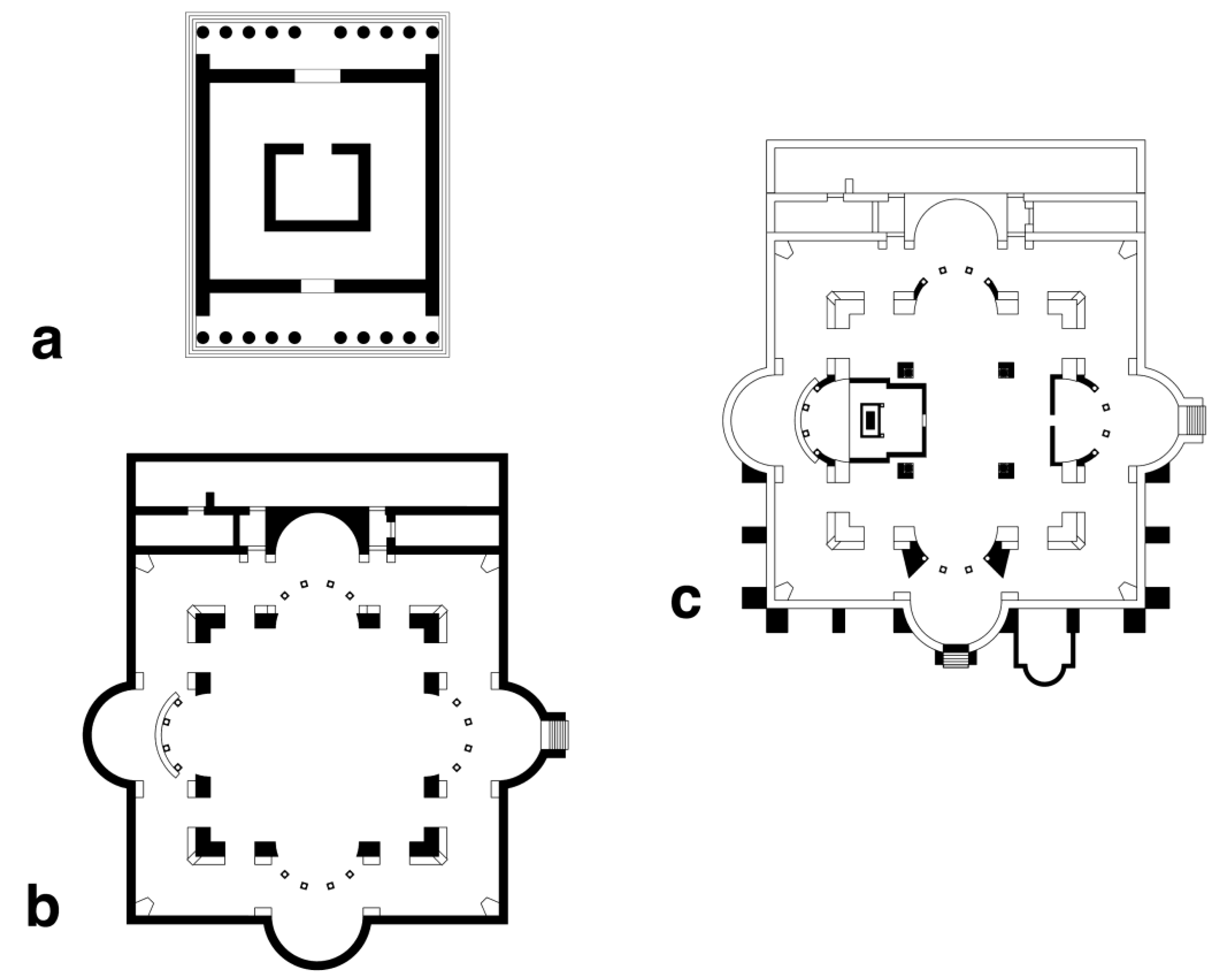
The Site of the Italic Temple and the St. Leucio Basilica
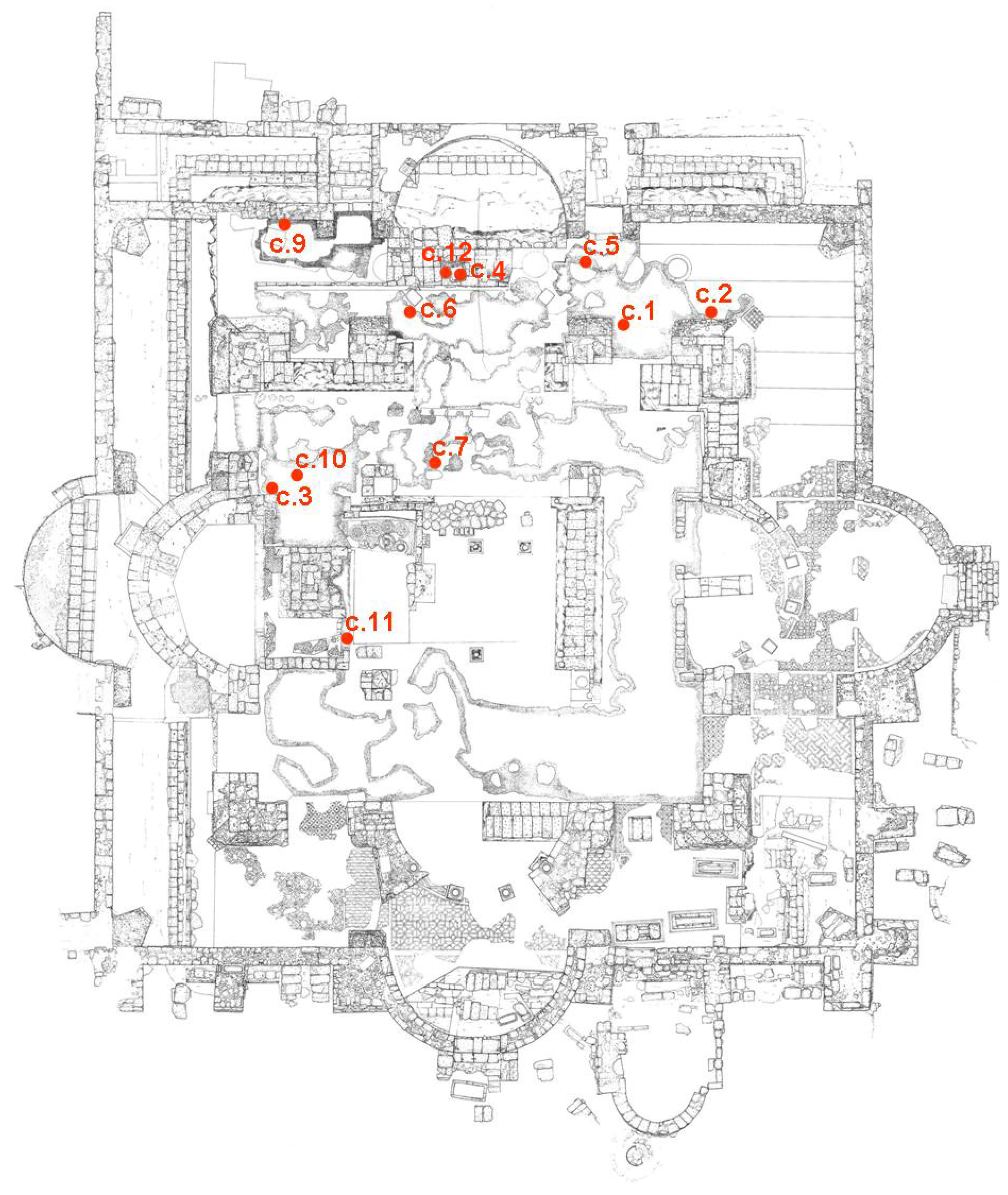
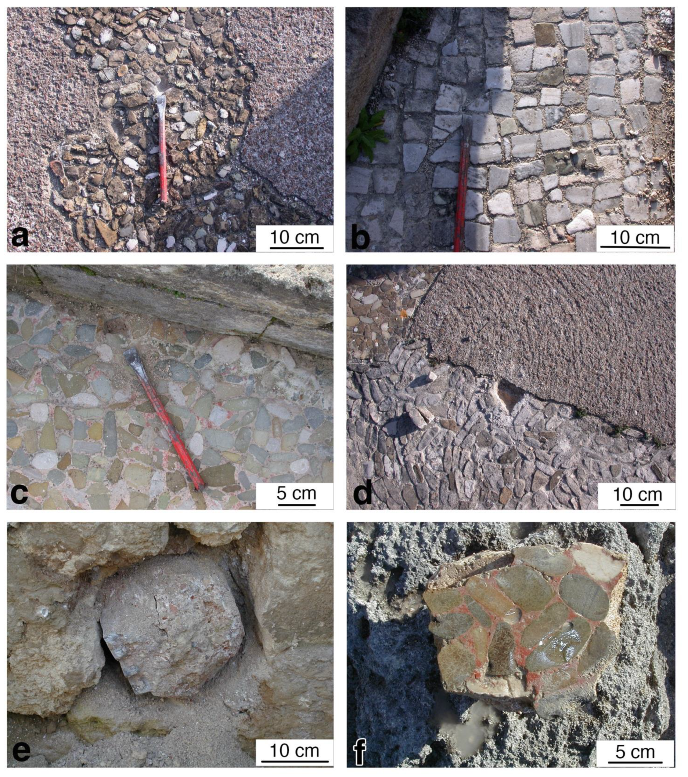
2. Sampling and Material
3. Methods
4. Results
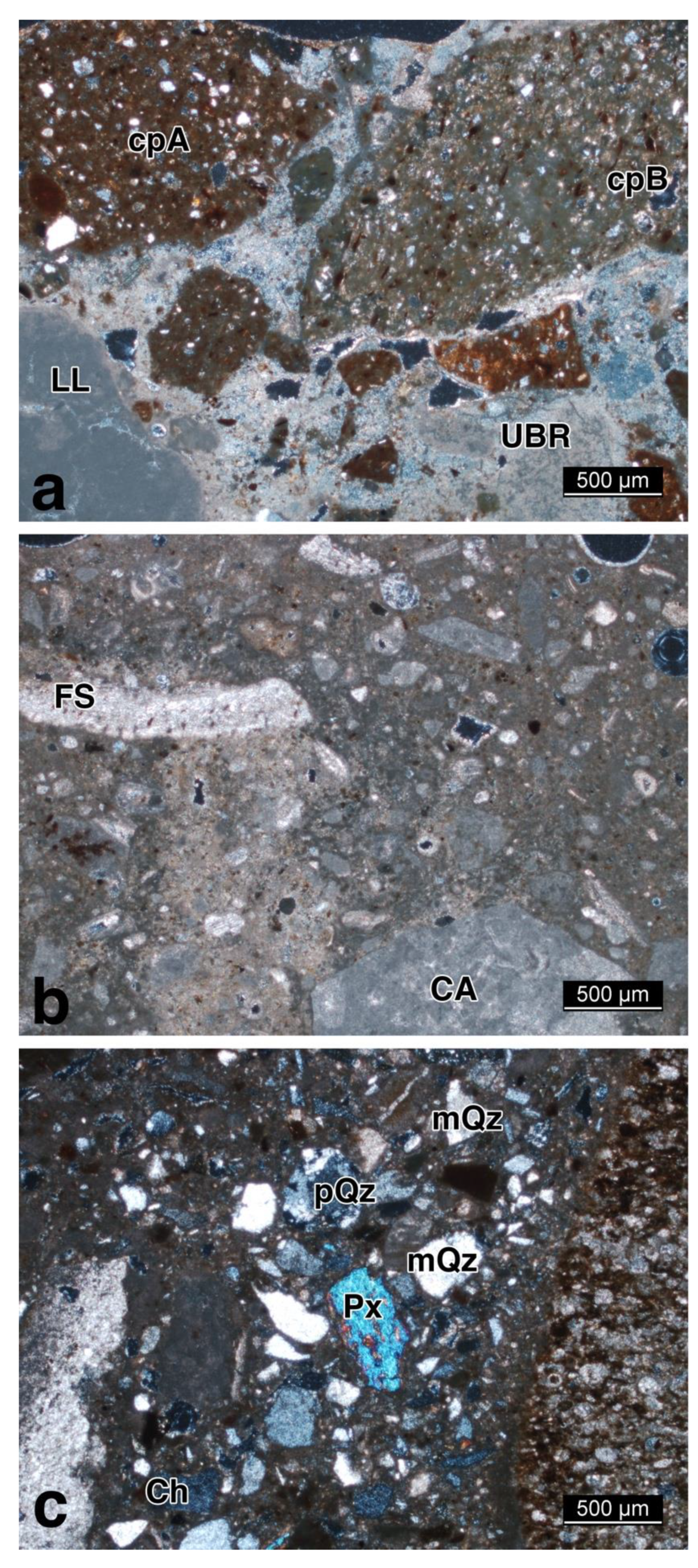
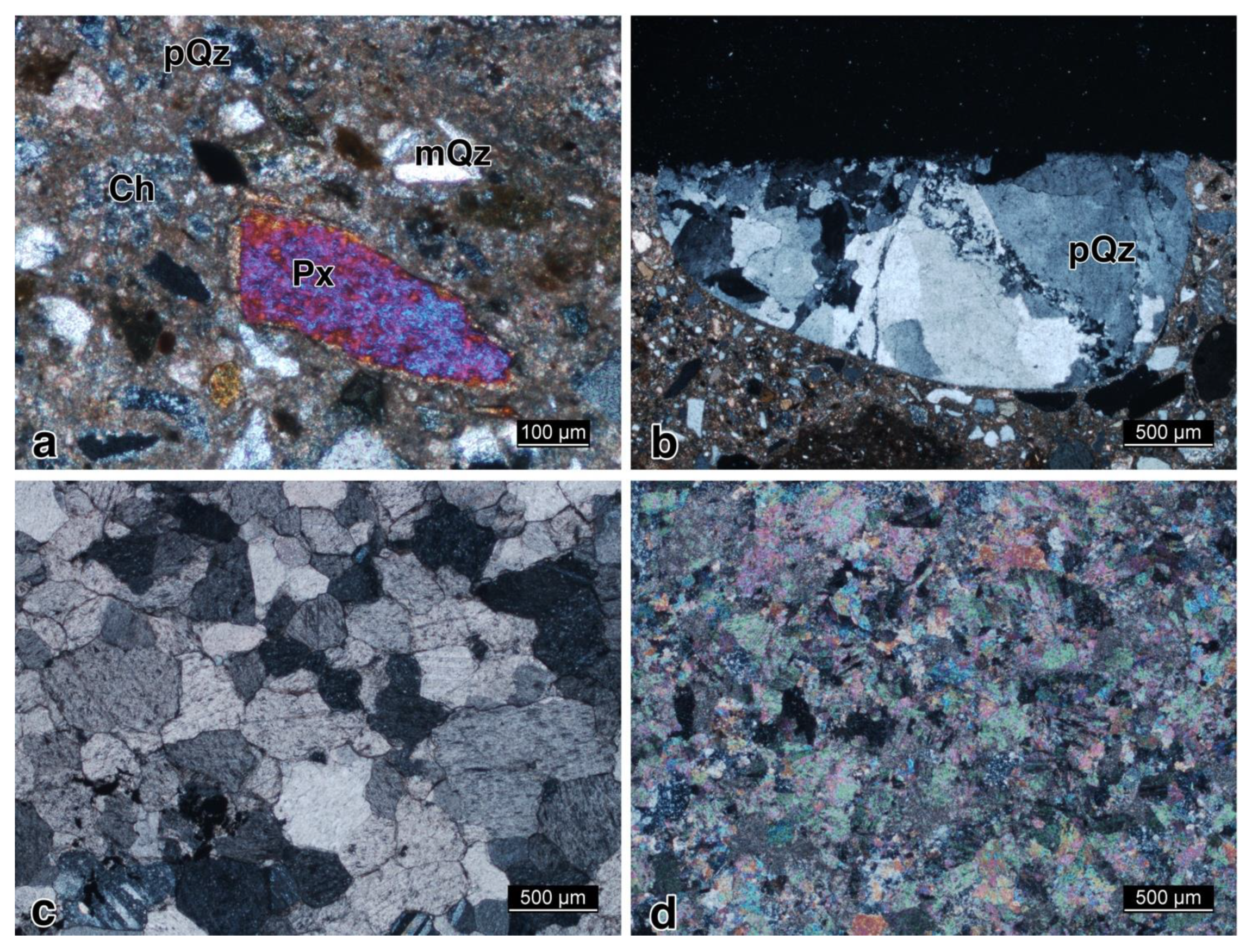
4.1. Petrography
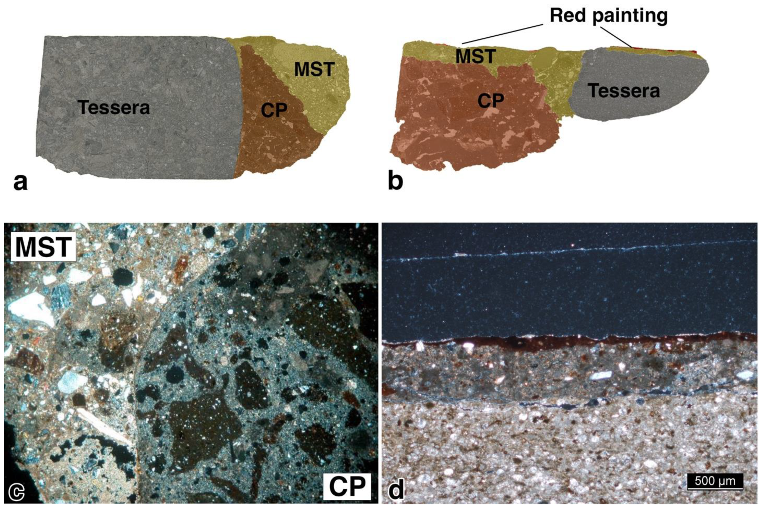
4.2. CP Group
4.3. MIC Group
4.4. MST Group
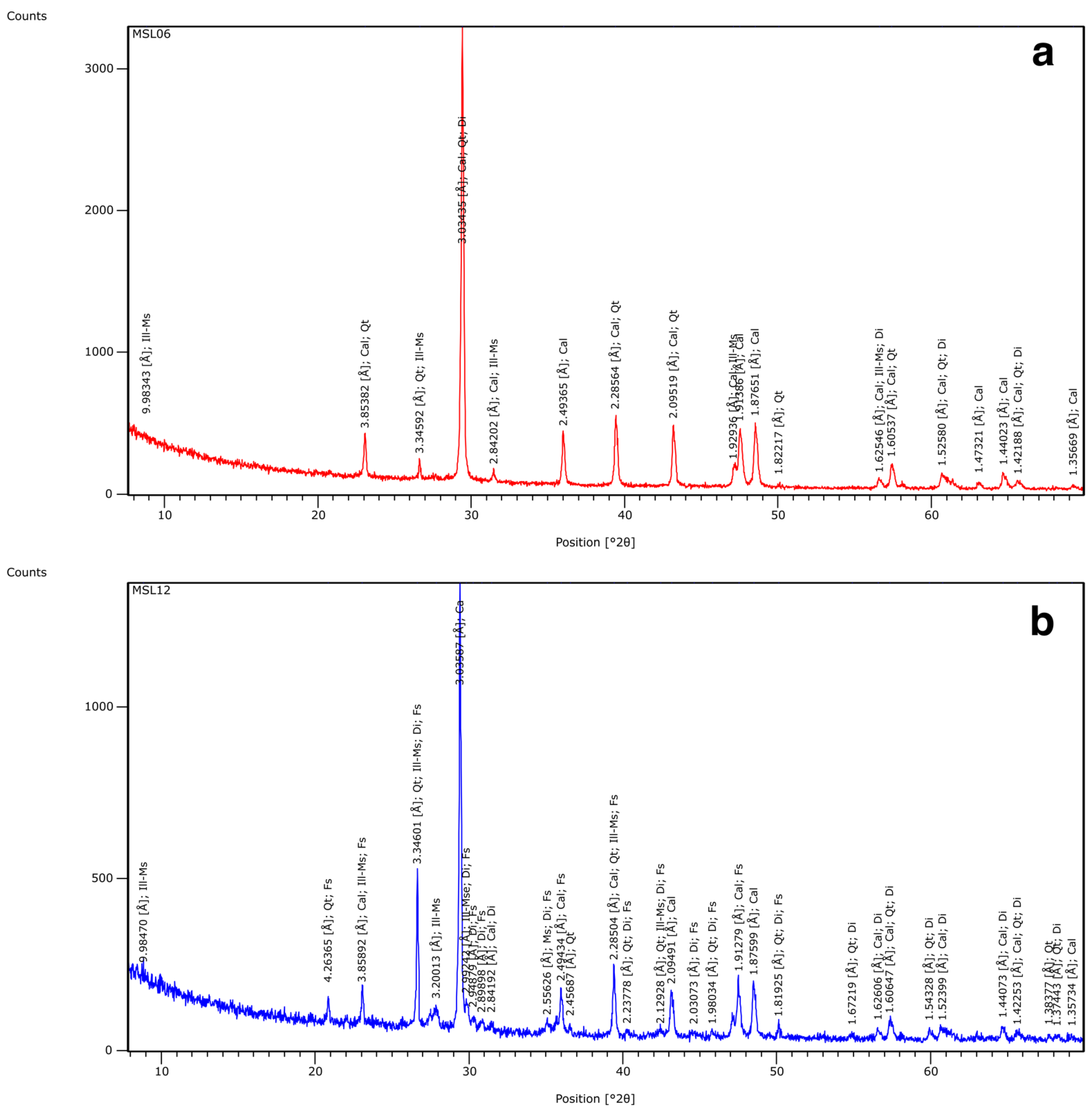
4.5. Mineralogy
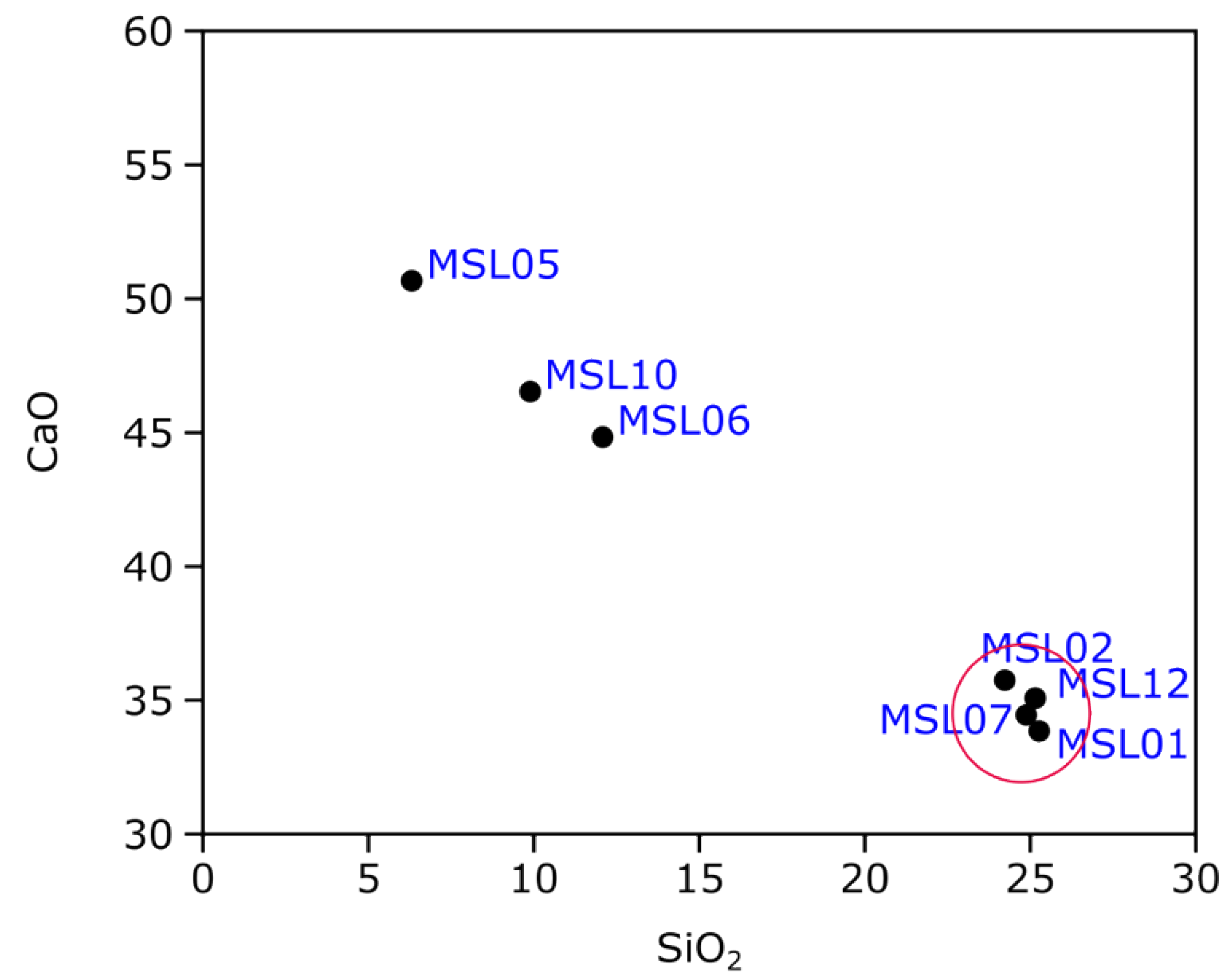
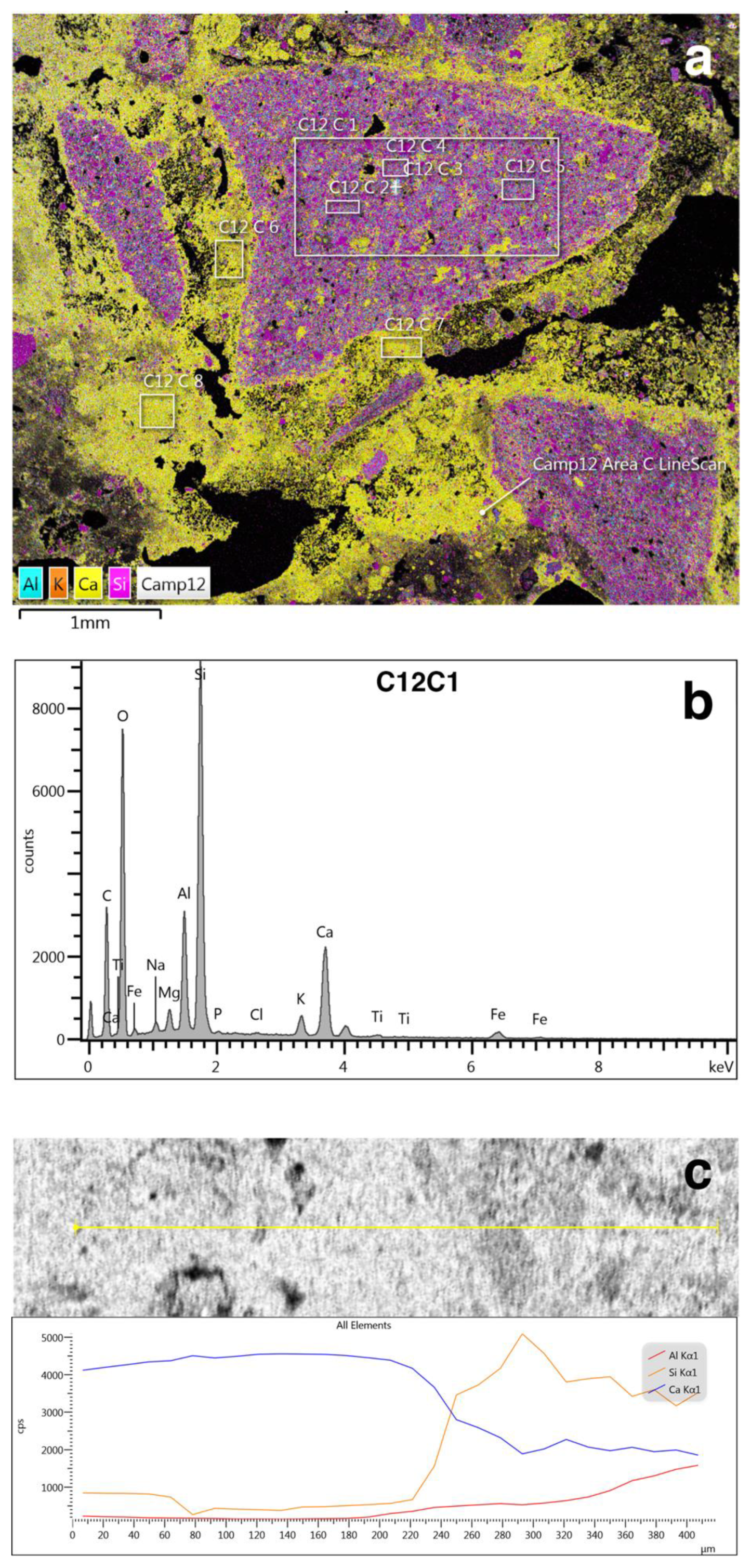
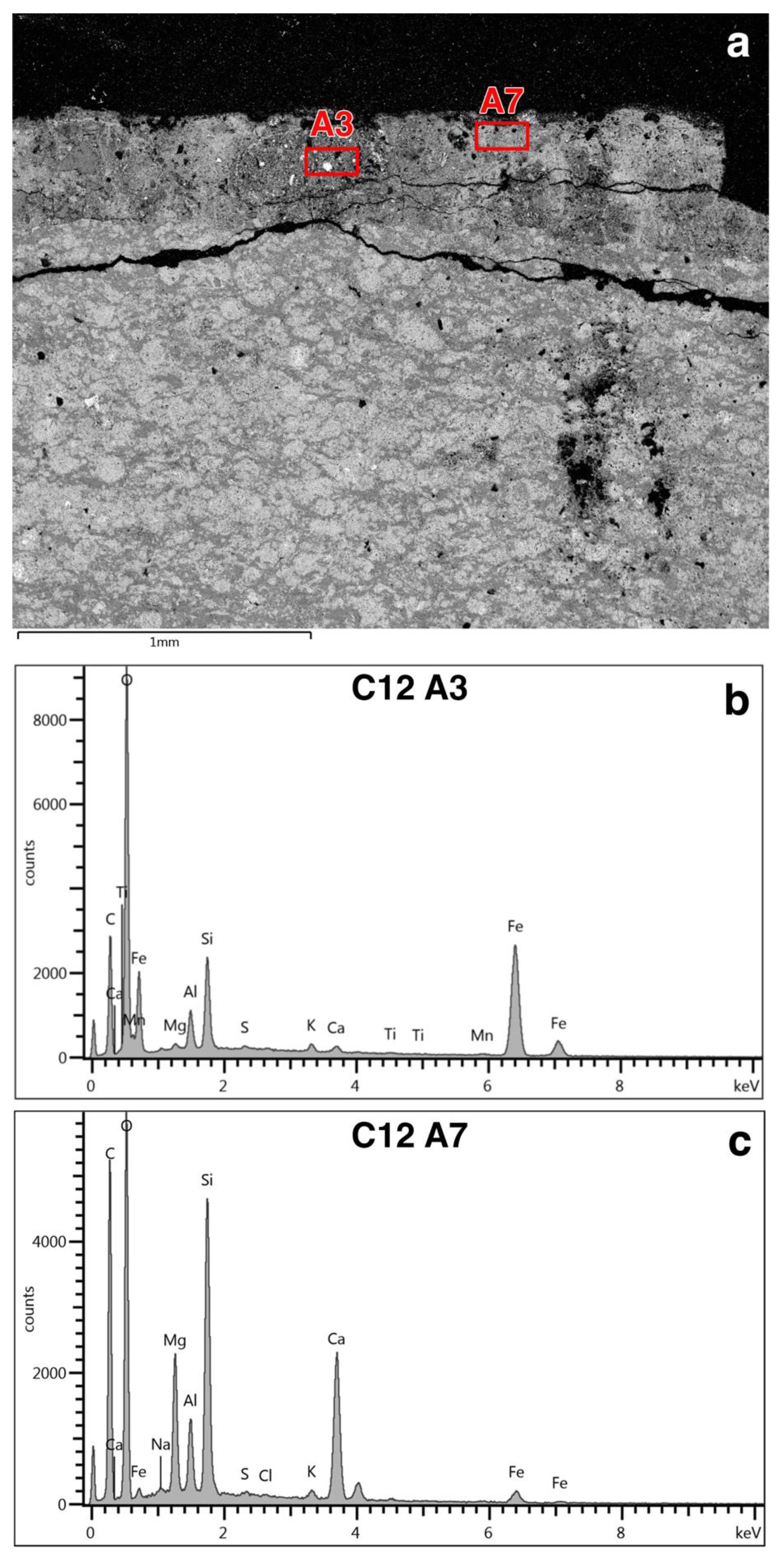
4.6. Chemical Composition
5. Discussion
6. Conclusions
Supplementary Materials
Author Contributions
Funding
Data Availability Statement
Conflicts of Interest
References
- Di Bella, M.; Quartieri, S.; Sabatino, G.; Santalucia, F.; Triscari, M. The glass mosaics tesserae of “Villa del Casale” (Piazza Armerina, Italy): A multi-technique archaeometric study. Archaeol. Anthropol. Sci. 2013, 6, 345–362. [Google Scholar] [CrossRef]
- Izzo, F.; Arizzi, A.; Cappelletti, P.; Cultrone, G.; De Bonis, A.; Germinario, C.; Graziano, S.F.; Grifa, C.; Guarino, V.; Mercurio, M.; et al. The Art of Building in the Roman Period (89 B.C.–79 A.D.): Mortars, Plasters and Mosaic Floors from Ancient Stabiae (Naples, Italy). Constr. Build. Mater. 2016, 117, 129–143. [Google Scholar] [CrossRef]
- Calia, A.; Lettieri, M.; Leucci, G.; Matera, L.; Persico, R.; Sileo, M. The mosaic of the crypt of St. Nicholas in Bari (Italy): Integrated GPR and laboratory diagnostic study. J. Archaeol. Sci. 2013, 40, 4162–4169. [Google Scholar] [CrossRef]
- Secco, M.; Dilaria, S.; Addis, A.; Bonetto, J.; Artioli, G.; Salvadori, M. The Evolution of the Vitruvian Recipes over 500 Years of Floor-Making Techniques: The Case Studies of the Domus delle Bestie Ferite and the Domus di Tito Macro (Aquileia, Italy). Archaeometry 2018, 60, 185–206. [Google Scholar] [CrossRef]
- Mantzana, E.; Zimi, E.; Kazolian, A.; Iliopoulos, I. The analysis of floor mosaic mortar substrates of Ancient Messene, southern Peloponnese, Greece. First results of materials identification and technological characteristics research. J. Archaeol. Sci. Rep. 2024, 54, 104448. [Google Scholar] [CrossRef]
- Laviano, R.; Vona, F.; Damato, B.; Grimaldi, E. I Mosaici Della Basilica Di San Leucio in Canosa. In Atti del IX Colloquio AISCOM; Edizioni del Girasole: Tivoli, Italy, 2004; pp. 387–398. [Google Scholar]
- Laviano, R.; Vona, F.; Carrara, I.; Nicolardi, D.; Nuzzo, E. I mosaici del complesso episcopale paleocristiano di San Pietro a Canosa. In Proceedings of the I Mosaici del Complesso Episcopale Paleocristiano di San Pietro a Canosa. Atti XI Colloquio AISCOM, Ancona, Italy, 16–19 February 2005; pp. 465–476. [Google Scholar]
- Laviano, R.; Vona, F.; Melone, N.; Borrelli, M.; Calcagno, B.; Formigone, P.; Zito, G.M. I mosaici del Battistero di San Giovanni a Canosa di Puglia: Analisi chimico-mineralogiche di materiali lapidei, cotti e strati preparatori. In Atti X Colloquio AISCOM; Edizioni del Girasole: Lecce, Italy, 2005; pp. 549–560. [Google Scholar]
- Laviano, R.; Vona, F.; Acquafredda, P.; Melone, N.; Bisceglia, V.; Borrelli, M.D.; Calcagno, B.; Formicone, P.; Zito, G.M. I mosaici del battistero di San Giovanni a Canosa di Puglia: Caratterizzazione dei materiali lapidei. In La Diagnostica per la Tutela dei Materiali e del Costruito; eBay: Caserta, Italy, 2003; pp. 103–116. [Google Scholar]
- Pensabene, P.; D’Alessio, A. Da Minerva a San Leucio: Parco Archeologico e Antiquario di San Leucio a Canosa; Comune di Canosa di Puglia. 2009. Available online: https://iris.uniroma1.it/handle/11573/63545 (accessed on 17 May 2025).
- Falla Castelfranchi, M. La Basilica Detta Di San Leucio a Canosa. In Puglia Preromanica dal V Secolo agli Inizi dell’XI; Bertelli, G., Ed.; Jaca Book: Bari, Italy, 2004; pp. 67–72. [Google Scholar]
- Giuliani, R.; Favia, P.; Giuliani, R. Canosa, Basilica Di San Leucio. In Edifici di Culto dell’Apulia tra Tardo Antico e Altomedioevo: Recenti Acquisizioni; Volpe, G., Favia, P., Giuliani, R., Eds.; Hortis Artium Medievalium: Zagreb-Motovun, Istria, 2023; pp. 55–93. [Google Scholar]
- De Lachenal, L. Spolia: Uso e Reimpiego Dell’antico Dal III al XIV Secolo; Biblioteca di Archeologia; Longanesi: Milan, Italy, 1995. [Google Scholar]
- Wolf, M. Die Architektur Des Tempels von San Leucio in Canosa. RM 2019, 125, 49–102. [Google Scholar]
- D’Alessio, A. Architettura Sacra In Daunia Tra Tarda Repubblica E Primo Impero Il Tempio In Località San Leucio A Canosa. In Archeologia Classica; L’Erma di Bretschneider: Rome, Italy, 2019; Volume 70, pp. 225–256. [Google Scholar]
- D’Alessio, A.; Gallocchio, E.; Manganelli, L.; Pensabene, P. La Basilica Di San Leucio a Canosa Di Puglia. Fasi Edilizie, Apparati Musivi e Necropoli. In Martiri, Santi, Patroni: Per una Archeologia Della Devozione. Atti del X Congresso Nazionale di Archeologia Cristiana (Università della Calabria, 15–18 Settembre 2010); Coscarella, A., De Santis, P., Eds.; Università della Calabria: Rossano, Italy, 2012; pp. 677–685. [Google Scholar]
- Pensabene, P.; D’Alessio, A. Il Complesso Di San Leucio Alla Luce Dei Nuovi Scavi 2005–2006. In Canosa. Ricerche Storiche 2007; Bertoldi Lenoci, L., Ed.; Edizioni Pugliesi: Martina Franca, Italy, 2008; pp. 105–142. [Google Scholar]
- Falla Castelfranchi, M. Canosa Nel VI Sec. Fra Roma e Costantinopoli. In Uomo di Dialogo e di Pace tra Oriente e Occidente. Anno Domini 2002; Bertoldi Le Noci, L., Ed.; Edizioni Pugliesi: Canosa di Puglia, Italy, 2002; pp. 77–93. [Google Scholar]
- Kleinbauer, W.E. The Origin and Functions of the Aisled Tetraconch Churches in Syria and Northern Mesopotamia. Dumbart. Oaks Pap. 1973, 27, 89–114. [Google Scholar] [CrossRef]
- D’Alessio, A.; Pensabene, P. Vecchi e Nuovi Dati Sulle Pavimentazioni e i Mosaici Dell’area Di San Leucio a Canosa. In Atti del XIII Colloquio AISCOM; Scripta Manent: Tivoli, Italy, 2008; pp. 23–40. [Google Scholar]
- Schettini, F. Nuovi Elementi per Lo Studio Del Romanico Pugliese. In Scritti in Onore di M. Salmi; Edizioni Scientifiche Italiane: Roma, Italy, 1961; pp. 264–265. [Google Scholar]
- De Tommasi, G. Canosa. Basilica Di San Leucio. In Restauri in Puglia 1971–1983, II. Catalogo Della Mostra (Bari); Edizioni Scientifiche Italiane: Fasano di Puglia, Italy, 1983; pp. 155–158. [Google Scholar]
- Corrente, M.; Vona, F. Mosaici Tardoantichi Di Canosa. Prospettive Di Recupero e Analisi Del Rischio. Vecchi e Nuovi Interventi Delle Soprintendenze Pugliesi a Confronto. In Apparati musivi antichi nell’area del Mediterraneo. Atti del Convegno Internazionale di Studi, Piazza Armerina 2003; GRI Library: Palermo, Italy, 2004; Volume 1, pp. 521–533. [Google Scholar]
- Hughes, J.J.; Válek, J.; Groot, C.J.W.P. (Eds.) Historic Mortars; Springer International Publishing: Cham, Switzerland, 2019. [Google Scholar] [CrossRef]
- Gliozzo, E.; Pizzo, A.; La Russa, M.F. Mortars, Plasters and Pigments—Research Questions and Sampling Criteria. Archaeol. Anthropol. Sci. 2021, 13, 193. [Google Scholar] [CrossRef]
- Matthew, A.; Woods, A.; Oliver, C. Spots before the Eyes: New Comparison Charts for Visual Percentage Estimation in Archaeological Material. In Recent Developments in Ceramic Petrology; Middleton, A., Freestone, I., Eds.; British Museum Occasional Paper; British Museum: London, UK, 1991; pp. 221–263. [Google Scholar]
- Franzini, M.; Leoni, L.; Saitta, M. A simple method to evaluate the matrix effects in X-Ray fluorescence analysis. X-Ray Spectrom. 1972, 1, 151–154. [Google Scholar] [CrossRef]
- Franzini, M.; Leoni, L.; Saitta, M. Revisione di una metodologia analitica per fluorescenza-X, basata sulla correzione completa degli effetti di matrice. Rend. Soc. Ital. Mineral. Petrol. 1975, 31, 365–378. [Google Scholar]
- Leoni, L.; Saitta, M. Determination of yttrium and niobium on standard silicate rocks by X-ray fluorescence analyses. X-Ray Spectrom. 1976, 5, 29–30. [Google Scholar] [CrossRef]
- Pouchou, J.-L.; Pichoir, F. Quantitative Analysis of Homogeneous or Stratified Microvolumes Applying the Model “PAP”. In Electron Probe Quantitation; Heinrich, K.F.J., Newbury, D.E., Eds.; Springer: Boston, MA, USA, 1991; pp. 31–75. [Google Scholar] [CrossRef]
- Eramo, G.; Clausi, M.; Fioretti, G.; Pinto, D. The Use of Lime over the Centuries: The Complexity of the Apulian Built Heritage. Minerals 2024, 14, 91. [Google Scholar] [CrossRef]
- Franzini, M.; Leoni, L.; Lezzerini, M.; Sartori, F. On the Binder of Some Ancient Mortars. Mineral. Petrol. 1999, 67, 59–69. [Google Scholar] [CrossRef]
- Fioretti, G.; Garavelli, A.; Germinario, G.; Pinto, D. Archaeometric Study of Wall Rock Paintings from the Sant’Angelo in Criptis Cave, Santeramo in Colle, Bari: Insights on the Rupestrian Decorative Art in Apulia (Southern Italy). Archaeol. Anthropol. Sci. 2021, 13, 168. [Google Scholar] [CrossRef]
- Bruno, P.; Calabrese, D.; Di Pierro, M.; Genga, A.; Laganara, C.; Manigrassi, D.A.P.; Traini, A.; Ubbrìaco, P. Chemical–Physical and Mineralogical Investigation on Ancient Mortars from the Archaeological Site of Monte Sannace (Bari—Southern Italy). Thermochim. Acta 2004, 418, 131–141. [Google Scholar] [CrossRef]
- Eramo, G.; Pinto, D.; Laviano, R.; Laganara, C.; Busto, A. Archeometrical Characterization of Lime Mortars from Sipontum (Foggia, 11th–13th Century AD). Plinius 2009, 35, 619. [Google Scholar]
- Fratini, F. L’idraulicità delle malte: Il contributo della diagnostica minero-petrografica. ARKOS 2010, 22, 40–44. [Google Scholar]
- Rattazzi, A.; Linee Guida per la Caratterizzazione di una Malta Storica e per la Malta da Intervento. Giornata di Aggiornamento Sulla Normativa Tecnica per la Conservazione dei Beni Culturali, L’Aquila 2010. Available online: https://portale.assimpredilance.it/uploads/allegati/5_linee_guida_caratteriazzazione_di_una_malta_storica.pdf (accessed on 17 May 2025).
- Elsen, J. Microscopy of Historic Mortars—A Review. Cem. Concr. Res. 2006, 36, 1416–1424. [Google Scholar] [CrossRef]
- Oates, J.A.H. Lime and Limestone: Chemistry and Technology, Production and Uses; Wiley-VCH: Weinheim, Germany, 1998. [Google Scholar]
- Leslie, A.B.; Hughes, J.J. Binder Microstructure in Lime Mortars: Implications for the Interpretation of Analysis Results. Q. J. Eng. Geol. Hydrogeol. 2002, 35, 257–263. [Google Scholar] [CrossRef]
- Bakolas, A.; Biscontin, G.; Moropoulou, A.; Zendri, E. Characterization of the Lumps in the Mortars of Historic Masonry. Thermochim. Acta 1995, 269–270, 809–816. [Google Scholar] [CrossRef]
- Moropoulou, A.; Bakolas, A.; Bisbikou, K. Investigation of the Technology of Historic Mortars. J. Cult. Herit. 2000, 1, 45–58. [Google Scholar] [CrossRef]
- Singh, V.K. The Science and Technology of Cement and Other Hydraulic Binders; Elsevier Science & Technology: San Diego, CA, USA, 2023. [Google Scholar]
- Miriello, D.; Bloise, A.; Crisci, G.M.; De Luca, R.; De Nigris, B.; Martellone, A.; Osanna, M.; Pace, R.; Pecci, A.; Ruggieri, N. New Compositional Data on Ancient Mortars and Plasters from Pompeii (Campania—Southern Italy): Archaeometric Results and Considerations about Their Time Evolution. Mater. Charact. 2018, 146, 189–203. [Google Scholar] [CrossRef]
- Miriello, D.; Antonelli, F.; Apollaro, C.; Bloise, A.; Bruno, N.; Catalano, M.; Columbu, S.; Crisci, G.M.; De Luca, R.; Lezzerini, M.; et al. A Petro-Chemical Study of Ancient Mortars from the Archaeological Site of Kyme (Turkey). Period. Mineral. 2015, 84, 497–517. [Google Scholar] [CrossRef]
- Cantisani, E.; Pecchioni, E.; Fratini, F. Optical and Electronic Microscope for Minero-Petrographic and Microchemical Studies of Lime Binders of Ancient Mortars. Minerals 2022, 12, 41. [Google Scholar] [CrossRef]
- Dilaria, S.; Secco, M.; Bonetto, J.; Ricci, G.; Artioli, G. Making Ancient Mortars Hydraulic. How to Parametrize Type and Crystallinity of Reaction Products in Different Recupes; Bokan Bosiljkov, V., Padovnik, A., Turk, T., Eds.; Conservation and Restoration of Historic Mortars and Masonry Structures; HMC 2022, RILEM Bookseries 42; Springer: Cham, Switzerland, 2023; pp. 36–52. [Google Scholar]
- Weber, J.; Baragona, A.; Pintér, F.; Gosselin, C. Hydraulicity in Ancient Mortars: Its Origin and Alteration Phenomena Under the Microscope. In Proceedings of the 15th Euroseminar on Microscopy Applied to Building Materials, 15th EMABM, Delft, The Netherlands, 17–19 June 2015. [Google Scholar]
- Elsen, J.; Van Balen, K.; Mertens, G. Hydraulicity in Historic Lime Mortars: A Review. In Historic Mortars; Válek, J., Hughes, J.J., Groot, C.J.W.P., Eds.; RILEM Bookseries; Springer Netherlands: Dordrecht, The Netherlands, 2012; Volume 7, pp. 125–139. [Google Scholar] [CrossRef]
- Ioannou, I.; Ilia, A.; Philokyprou, M. Use of Crushed Fired Clay Ceramics in the Production of Mortars. In WIT Transactions on Ecology and the Environment; WIT Press: Southampton, UK, 2009; pp. 257–264. [Google Scholar] [CrossRef]
- Arizzi, A.; Cultrone, G. Aerial Lime-Based Mortars Blended with a Pozzolanic Additive and Different Admixtures: A Mineralogical, Textural and Physical-Mechanical Study. Constr. Build. Mater. 2012, 31, 135–143. [Google Scholar] [CrossRef]
- Charola, A.E.; Henriques, F.M.A. Hydraulicity in lime mortars revisited. Historic Mortars: Characteristics and Tests: Proceedings of a RILEM Workshop. Paisley 1999, 2000, 95–104. [Google Scholar]
- Rispoli, C.; Montesano, G.; Verde, M.; Balassone, G.; Columbu, S.; De Bonis, A.; Di Benedetto, C.; D’Uva, F.; Esposito, R.; Graziano, S.F.; et al. The Key to Ancient Roman Mortars Hydraulicity: Ceramic Fragments or Volcanic Materials? A Lesson from the Phlegrean Archaeological Area (Southern Italy). Constr. Build. Mater. 2024, 411, 134408. [Google Scholar] [CrossRef]
- Bakolas, A.; Biscontin, G.; Moropoulou, A.; Zendri, E. Characterization of Structural Byzantine Mortars by Thermogravimetric Analysis. Thermochim. Acta 1998, 321, 151–160. [Google Scholar] [CrossRef]
- Gliozzo, E. Ceramic technology: How to reconstruct the firing process. Archaeol. Anthropol. Sci. 2020, 12, 260. [Google Scholar] [CrossRef]
- Fort, R.; Varas-Muriel, M.J.; Zoghlami, K.; Ergenç, D.; Zaddem, A. Analytical Characterisation of 1st- and 2nd-Century Roman Mortars at the Utica Archaeological Site (Tunisia): Construction Phases and Provenance of the Raw Materials. J. Archaeol. Sci. Rep. 2024, 54, 104404. [Google Scholar] [CrossRef]
- Carò, F.; Riccardi, M.P.; Mazzilli Savini, M.T. Characterization Of Plasters And Mortars As A Tool In Archaeological Studies: The Case Of Lardirago Castle In Pavia, Northern Italy. Archaeometry 2008, 50, 85–100. [Google Scholar] [CrossRef]
- Milanesio, E.; Storta, E.; Gambino, F.; Appolonia, L.; Borghi, A.; Glarey, A. Petrographic Characterization of Historic Mortar as a Tool in Archaeologic Study: Examples from Two Medieval Castles of Aosta Valley, Northwestern Italy. J. Archaeol. Sci. Rep. 2022, 46, 103719. [Google Scholar] [CrossRef]
- Miriello, D.; Barca, D.; Bloise, A.; Ciarallo, A.; Crisci, G.M.; De Rose, T.; Gattuso, C.; Gazineo, F.; La Russa, M.F. Characterisation of Archaeological Mortars from Pompeii (Campania, Italy) and Identification of Construction Phases by Compositional Data Analysis. J. Archaeol. Sci. 2010, 37, 2207–2223. [Google Scholar] [CrossRef]
- Galli, A.; Caccia, M.; Bonizzoni, L.; Gargano, M.; Ludwig, N.; Poldi, G.; Martini, M. Deep inside the Color: How Optical Microscopy Contributes to the Elemental Characterization of a Painting. Microchem. J. 2020, 155, 104730. [Google Scholar] [CrossRef]
- Mastrotheodoros, G.P.; Beltsios, K.G. Pigments—Iron-Based Red, Yellow, and Brown Ochres. Archaeol. Anthropol. Sci. 2022, 14, 35. [Google Scholar] [CrossRef]
- Elias, M.; Chartier, C.; Prévot, G.; Garay, H.; Vignaud, C. The Colour of Ochres Explained by Their Composition. Mater. Sci. Eng. B 2006, 127, 70–80. [Google Scholar] [CrossRef]


| Sample | Material | Mortar Stratigraphy | Pavement Type | Building Phase | Analitical Methods | |||
|---|---|---|---|---|---|---|---|---|
| OM | XRPD | XRF | SEM-EDS | |||||
| MSL01 | Mortar | Not layered | 4 | Temple | x | x | x | - |
| MSL02 | Mortar, red painting | Not layered | 4 | Temple | x | x | x | - |
| MSL03 | Pebble, mortar, red painting | Layered | 3 | Temple | x | - | - | - |
| MSLC03 | Pebble, mortar, red painting | Layered | 3 | Temple | x | - | - | - |
| MSL04 | Pebbles, mortar, red painting | Not layered | 3 | Before the building of the basilica | x | x | x | - |
| MSL05 | Mortar | Not layered | 4 | Basilica | x | x | x | - |
| MSL06 | Mortar | Not layered | 1 | Unknown | x | x | x | - |
| MSL07 | Mortar | Not layered | 1 | Unknown | x | x | x | - |
| MSL09 | Mortar, Pebble | Not layered | 2 | Unknown | x | - | - | - |
| MSL10 | Mortar | Not layered | - | Unknown | x | x | x | x |
| MSL11 | Mortar, red painting | Layered | 3 | Temple | x | x | x | - |
| MSL12 | Mortar, red painting | Not layered | - | Unknown | x | x | x | x |
| Group | Subgroup | Samples | Binder | Aggregate | Pore Roundness |
|---|---|---|---|---|---|
| CP | - | MSL01, MSL02, MSL03_A, MSLC03_B, MSL04, MSL07, MSL11_B, MSL12 | Variable-texture binder, underburnt relicts, lime lumps | Cocciopesto A, cocciopesto B, mono- and polycrystalline quartz, pyroxenes, lithic fragments | Angular |
| MIC | MIC1 | MSL05 | Homogeneous | Micritic fragments | Rounded |
| MIC2 | MSL06, MSL10 | Homogeneous | Micritic fragments, fossils | Rounded | |
| MST | - | MSL03_B, MSLC3_A, MSL11_A | Variable-texture binder, lime lumps | Chert fragments, limestone fragments, mono- and polycrystalline quartz, feldspars, pyroxenes, amphiboles | Angular and rounded pores (very rare) |
| Sample | Cal | Qt | KFs | Ill-Ms | Di | Gh |
|---|---|---|---|---|---|---|
| MSL01 | 4 | 3 | 1 | tr | - | tr |
| MSL02 | 4 | 3 | 1 | tr | tr | - |
| MSL05 | 5 | 1 | tr | tr | - | - |
| MSL06 | 5 | tr | - | tr | - | - |
| MSL07 | 5 | 3 | tr | tr | - | - |
| MSL10 | 4 | tr | 1 | tr | - | - |
| MSL12 | 4 | 3 | 1 | tr | tr | tr |
| Sample | SiO2 | TiO2 | Al2O3 | Fe2O3 | MgO | MnO | K2O | Na2O | CaO | P2O5 | LOI |
|---|---|---|---|---|---|---|---|---|---|---|---|
| MSL01 | 25.27 | 0.38 | 6.37 | 3.03 | 2.48 | 0.07 | 1.03 | 0.23 | 33.85 | 0.18 | 27.11 |
| MSL02 | 24.23 | 0.35 | 5.71 | 2.77 | 1.53 | 0.07 | 1.67 | 0.26 | 35.75 | 0.21 | 27.46 |
| MSL05 | 6.31 | 0.09 | 1.82 | 0.58 | 0.90 | 0.04 | 0.19 | 0.07 | 50.67 | 0.11 | 39.21 |
| MSL06 | 12.08 | 0.14 | 3.18 | 1.40 | 1.01 | 0.05 | 1.35 | 0.32 | 44.83 | 0.13 | 35.51 |
| MSL07 | 25.15 | 0.16 | 3.15 | 1.51 | 1.10 | 0.07 | 0.97 | 0.27 | 35.08 | 0.13 | 35.41 |
| MSL10 | 9.89 | 0.11 | 2.73 | 1.17 | 0.95 | 0.06 | 1.14 | 0.27 | 46.53 | 0.13 | 37.02 |
| MSL12 | 24.88 | 0.37 | 6.40 | 3.02 | 1.65 | 0.07 | 1.57 | 0.71 | 34.45 | 0.13 | 26.76 |
| Sample | Area | Na2O | MgO | Al2O3 | SiO2 | P2O5 | SO3 | Cl | K2O | CaO | TiO2 | MnO | Fe2O3 |
|---|---|---|---|---|---|---|---|---|---|---|---|---|---|
| MSL10 | A (n = 11) | 0.78 | 1.36 | 7.17 | 30.26 | 0.00 | 0.42 | 0.21 | 2.88 | 54.44 | 0.18 | 0.00 | 2.30 |
| 0.31 | 0.46 | 1.68 | 4.48 | 0.00 | 0.41 | 0.18 | 0.63 | 8.30 | 0.32 | 0.00 | 0.99 | ||
| MSL12 | B1 (n = 7) | 0.54 | 1.29 | 4.19 | 18.09 | 0.00 | 0.09 | 0.16 | 1.24 | 73.64 | 0.00 | 0.00 | 0.74 |
| 0.26 | 0.56 | 2.82 | 10.73 | 0.00 | 0.25 | 0.22 | 0.88 | 14.00 | 0.00 | 0.00 | 0.74 | ||
| MSL12 | B2 (n = 3) | 0.62 | 1.41 | 6.15 | 36.85 | 0.00 | 0.00 | 0.21 | 1.31 | 50.87 | 0.00 | 0.00 | 2.58 |
| 0.23 | 0.22 | 0.44 | 13.39 | 0.00 | 0.00 | 0.19 | 0.04 | 13.97 | 0.00 | 0.00 | 0.28 |
Disclaimer/Publisher’s Note: The statements, opinions and data contained in all publications are solely those of the individual author(s) and contributor(s) and not of MDPI and/or the editor(s). MDPI and/or the editor(s) disclaim responsibility for any injury to people or property resulting from any ideas, methods, instructions or products referred to in the content. |
© 2025 by the authors. Licensee MDPI, Basel, Switzerland. This article is an open access article distributed under the terms and conditions of the Creative Commons Attribution (CC BY) license (https://creativecommons.org/licenses/by/4.0/).
Share and Cite
Fioretti, G.; D’Alessio, A.; Eramo, G. Archaeological Stratification in the St. Leucio Basilica (2nd Century BCE–6th Century CE, Canosa di Puglia, Southern Italy): Archaeometric Analysis of Pebble Pavements. Heritage 2025, 8, 186. https://doi.org/10.3390/heritage8060186
Fioretti G, D’Alessio A, Eramo G. Archaeological Stratification in the St. Leucio Basilica (2nd Century BCE–6th Century CE, Canosa di Puglia, Southern Italy): Archaeometric Analysis of Pebble Pavements. Heritage. 2025; 8(6):186. https://doi.org/10.3390/heritage8060186
Chicago/Turabian StyleFioretti, Giovanna, Alessandro D’Alessio, and Giacomo Eramo. 2025. "Archaeological Stratification in the St. Leucio Basilica (2nd Century BCE–6th Century CE, Canosa di Puglia, Southern Italy): Archaeometric Analysis of Pebble Pavements" Heritage 8, no. 6: 186. https://doi.org/10.3390/heritage8060186
APA StyleFioretti, G., D’Alessio, A., & Eramo, G. (2025). Archaeological Stratification in the St. Leucio Basilica (2nd Century BCE–6th Century CE, Canosa di Puglia, Southern Italy): Archaeometric Analysis of Pebble Pavements. Heritage, 8(6), 186. https://doi.org/10.3390/heritage8060186