Article

Contribution of EBSD for the Microstructural Study of Archaeological Iron Alloy Artefacts from the Archaeological Site of Loiola (Biscay, Northern Spain)

by
Céline Rémazeilles
1,*,
Maria Cruz Zuluaga
2,
Haizea Portillo-Blanco
2,
Egle Conforto
1,
Abdelali Oudriss
1,
Luis Àngel Ortega
2,
Ainhoa Alonso-Olazabal
2 and
Juan José Cepeda-Ocampo
3
1
Laboratory of Engineering Sciences for the Environment (LaSIE), UMR 7356 CNRS, La Rochelle University, Avenue Michel Crépeau, F-17042 La Rochelle Cedex 01, France
2
Department of Geology, Faculty of Science and Technology, University of the Basque Country (UPV/EHU), Sarriena s/n, E-48940 Leioa, Spain
3
Department of Historical Sciences, Faculty of Philosophy and Letters, University of Cantabria, E-39005 Santander, Spain
*
Author to whom correspondence should be addressed.
Heritage 2024, 7(6), 3179-3193; https://doi.org/10.3390/heritage7060150
Submission received: 24 April 2024 / Revised: 2 June 2024 / Accepted: 4 June 2024 / Published: 10 June 2024
(This article belongs to the Special Issue Conservation and Restoration of Metal Artifacts)

Abstract

:
Iron palaeometallurgy was carried out on three artefacts, classified as nails and excavated from the archaeological site of Loiola (La Arboleda, Biscay, northern Spain), to investigate Roman manufacturing techniques. Energy Dispersive Spectroscopy (EDS) coupled with Environmental Scanning Electron Microscopy (ESEM) and micro-Raman spectroscopy were used to obtain elemental composition and structural characterization of mineral phases. Metallurgical properties and crystallographic texture were studied by combining microscopic methods such as optical microscopy (OM), Electron Backscatter Diffraction realized in environmental mode (EBSD) and measurements of local Vickers microhardness. The three artefacts had different microstructures, distinguished by a large gradient of carbon content, although important segregations (inclusions) were observed in all of them. Two pearlite-rich artefacts showed a high density of structural defects (geometrically necessary dislocations and large crystallographic orientation gradients in pearlitic ferrite, curved pearlitic cementite) resulting from a high level of plastic deformation that occurred during the manufacturing process. The third artefact consisted of pure ferrite without structural defects. This one was clearly manufactured differently from the two others, so it probably had another functionality.

Graphical Abstract

1. Introduction

The study of iron technology in archaeological iron artefacts manufactured in ancient times has received growing interest in recent decades. Iron-making and -processing technology was developed during the “Iron Age” [1,2,3,4,5]. In the west of the Basque Country (North Spain), Etxezarraga [6] describes the state of the art of pre-hydraulic iron archaeometallurgy and mentions remains of iron metallurgy since the Iron Age (5th century BC) to the end of 13th century [6]. Thanks to the bloomery process, the use of iron expanded during the Roman period. Smelted iron was produced by reduction of iron ore with charcoal as fuel and reducing agent. Since the temperature of the furnace was not high enough to generate liquid iron, the obtained product was sponge iron mixed with silicate slags [7,8,9]. After, the slag-rich sponge was forged to extract the iron from the slag, producing wrought iron, low-carbon iron, and hypo-hypereutectoid steel [1,10,11]. In fact, archaeometallurgical analyses show that Romans used low carbon and phosphoric iron and a range of steel with carbon content ranging between 0.25% and 0.8% [11]. Selection of materials for iron object production was based on the ironworker’s knowledge [11,12]. However, the issue of production is made difficult to address due to the scarcity of study materials. Archaeological iron artefacts are rarely in a good state of conservation. Because of the occurrence of corrosion during burial or of post-excavation corrosion resumption due to inappropriate storage conditions, there is often very little metal substrate left. Indirect approaches were then adopted like developing studies on other kinds of steelmaking products such as semi-products (iron bars [13,14]) or by-products (slags [9,15]).
To address ancient iron production technology and iron object manufacturing, various analytical and microscopy methods have been used, e.g., [5,11,16,17,18,19,20,21,22,23,24]. Through Energy-Dispersive Spectroscopy (EDS) coupled with Scanning Electron Microscopy (SEM), elemental analysis can be obtained. Chemical composition and mainly the carbon content determine the mechanical behavior of iron artefacts. Iron with low carbon content leads to high ductility and poor strength but can be reinforced by carburization. In contrast, high carbon content iron under stress conditions can be easily damaged. However, archaeological iron-based artefacts are generally heterogeneous and can contain carburized zones generated during the smelting and smithing processes [13]. Although the mechanical properties of steel are determined mainly by the carbon content, the phosphorus content can also induce embrittlement effects reducing the toughness and ductility [25,26].
Microscopic observations allow for revealing the microstructure of a metal, with grain size, carbon content, and inclusions (morphology and distribution), and also for determining the morphology of the corrosion layers. Nevertheless, the heterogeneous feature of the microstructure of archaeological iron objects sometimes makes it difficult to use classical methods such as chemical attacks (etching) for metallographic observations. The latter is based on observations of the microstructure under an optical microscope (OM), but even easy to use, good quality images in the case of highly carburized zones are not so easy to obtain and the microstructure is therefore difficult to describe correctly.
In this article, a combination of metallographic observation methods (etching, OM, and SEM observations) and Electron Backscatter Diffraction (EBSD) applied to characterize the microstructure of iron artefacts dating from the Roman period are presented. In addition, microhardness measurements were performed and Raman microspectroscopy was used to achieve phase identification, especially inside inclusions. To our knowledge, the use of EBSD and microhardness measurements to characterize archaeological ferrous materials is scarce [27,28,29,30,31,32,33]. Rather intended for the characterization of the microstructure of modern commercial materials, especially metals, these methods are not very widespread for studying ancient practices. Like conventional methods, EBSD allows one to determine grain size information and carbide distribution, but as a high-resolution analytical method, additional information can be obtained by EBSD such as the phase identification and the texture of the material through the determination of crystallographic orientations of grains [34,35]. Grain boundary populations and dislocation distributions can be studied, and possible sub-structures can be revealed inside grains [36]. As a complementary method, microhardness measurement provides information linked to the nature of the phases and also to the local carbide content. Through such a fine level of observation, a correlation between microstructure and mechanical properties can be performed, bringing crucial information about the manufacturing processes. Through the analytical results obtained from the metallurgical study of three highly corroded objects, the potentialities and limits of these methods will be discussed.

2. Materials and Methods

2.1. Corpus and Archaeological Context

The archaeological site of Loiola is located within the mining complex of La Arboleda (Trapagaran, Biscay, Spain) (Figure 1). The extraction and processing of iron ore at La Arboleda has been continuous from the second Iron Age to current times (mid 20th century) [37,38,39]. Long-term iron production is related to the large iron mineral deposits hosted in Lower Albian limestones of the Basque-Cantabrian Basin [40]. Mineralization occurs in different forms from disseminated and massive to dike-hosted. The primary siderite was oxidized under supergenic conditions, forming secondary mineralization of hematite and goethite [6,41,42]. Exploitation of the hematite and goethite produced by alteration of the upper part of the siderite veins has been carried out since Roman times. The successive archaeological interventions carried out allowed the discovery of a series of sites of different chronologies [6,38,39,43,44,45]. Two of them showed evidence of archeometallurgical activity with pre-hydraulic iron production workshops known as mountainside ironworks [46,47].
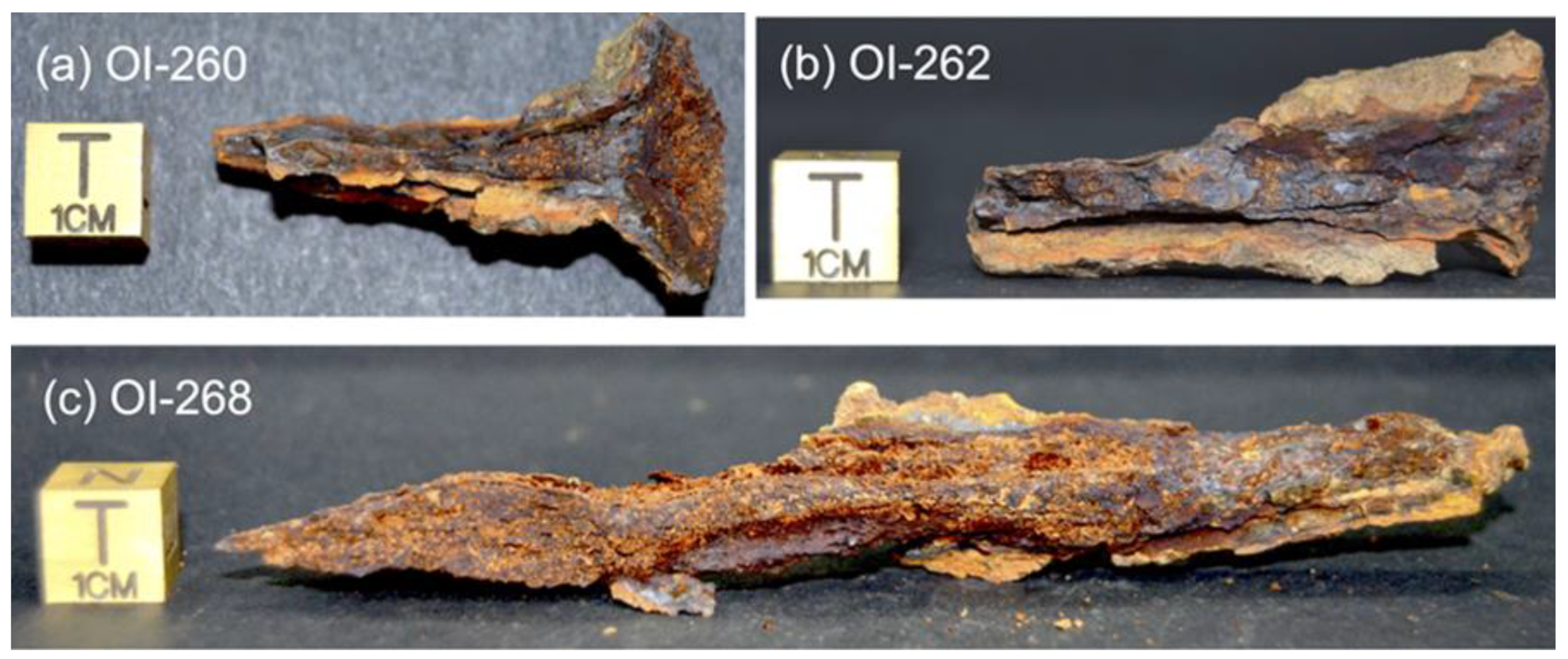
Analyzed samples correspond to three iron objects classified as nails and attributed to the Roman period (Figure 2). These show a heavily corroded surface and irregular shapes making it difficult to report their accurate dimensions. Sample OI-260 corresponds to a headed nail (Figure 2a), but corrosion made it impossible to determine the shape of the head (square or disk-like). Sample OI-262 (Figure 2b) was classified as a headless nail. Sample OI-268 (Figure 2c) was also classified as a headless nail although according to the morphology it cannot be ruled out that it could correspond to a tip of a tool or to a small punch. Although corrosion prevented an accurate classification of the artefacts, there was enough metal left to carry out metallurgical analyses.

2.2. Sample Preparation

For analysis, the artefacts were first embedded in epoxy resin. Then, in order to avoid corrosion resumption during the sampling, contact with water was prevented as far as possible. The nails were cut longitudinally with a diamond wire saw, using a mineral oil (Nujol) able to provide a protective film during the cutting.
Both sections of each nail were studied, one for metallographic observations and the other for microhardness measurement, SEM, and EBSD analysis.
Each section was pre-polished in heptane with silicon carbide discs until grade 4000 (grain size of 5 μm) and non-aqueous diamond suspensions were used for polishing until grain size of 1 μm (DP Suspensions A, Struers, Copenhagen, Denmark).
For metallographic observations under an optical microscope (OM), samples were etched with a 3 vol.% of HNO3 nitric acid in ethanol (3% Nital solution).
Since EBSD analysis required a finer polishing, just before experiments the dedicated section was polished again from P4000 to ¼ μm (DP-paste M, Struers) and finally with 0.03 μm colloidal silica (Suspension SPM colloidal silica 0.03 μm, Buehler) over several hours on a vibrating polisher using Buehler VibroMet™ 2. EBSD is coupled with the SEM and samples are placed in its analytic chamber. Since experiments were realized in environmental mode, surfaces were not coated with any sputtered conductor film.
In addition, preserving the samples immersed in heptane made it possible to avoid oxidation of their surfaces during the period of the various analytical tests. If necessary, they were polished again (P4000 to 1 μm).

2.3. Analytical Procedure and Methods

Preliminary examinations were carried out with an M165C Leica or an AxioZoom V16Zeiss optical stereomicroscope to select areas of interest for microanalysis.
Metallographic observations were carried out with a microscope (DMRM, Leica, Wetzlar, Germany) equipped with a digital camera for image acquisition (LAS software V3.8, Leica, Live Image Builder option).
Vickers microhardness measurements were performed on each sample using a Qness Mi-150 cro Hardness Tester M variant (Q10M) to evaluate the strength of the structural constituents, their quality, and their resistance. Since the expected iron phases have low hardness values, Brinell hardness scale conversion could be used when appropriate.
Environmental scanning electron microscopy with energy dispersive X-ray spectroscopy (ESEM-EDS) was applied for microstructure observations and for non-metallic inclusion elemental analysis. Experiments were conducted using the environmental FEI Quanta 200 FEG/ESEM apparatus coupled with an EDAX Genesis EDS system and an EDAX/TSL OIM Data Collection system for EBSD. Thanks to the introduction of water vapor in the specimen chamber, the environmental mode avoids surface charge accumulation and dehydration of non-conductor and/or humid samples and thus allows performing observations, EDS spectra, and EBSD analyses without any metallization. Thus, analytical SEM parameters such as 20 KV in accelerating voltage were used. For observations and EDS, the electron beam current was of 0.1 nA and water vapor pressure of 0.9 mbar. For EBSD, 5 nA and 0.3 mbar were used.
For EBSD analyses, samples were tilted 70° with respect to the horizontal inside the ESEM analysis chamber. A 50 mm retractable phosphor screen associated with a DIGIVIEW 4 CCD camera and controlled with IOM Collection 5 software was used to acquire diffraction data. Then, diffraction data analysis and grain orientation maps were realized thanks to the TSL OIM Analysis 8 software. The EBSD analyses were carried out by defining two phases, α-iron (BCC) and Fe3C-cementite (Orthorhombic), and the acquisition step varied from 0.2 to 2 µm according to the size of the area to be scanned. The obtained scans were then analyzed using TSL OIM Analysis 8 software which provides information about the crystallographic phases present in the sample as well as the grain texture and also calculates the average grain size.
Micro-Raman spectroscopy analysis was carried out on a Jobin Yvon High Resolution spectrometer (LabRAM HR) coupled with a microscope (Olympus BX41, Tokyo, Japan) and a Peltier-based cooled charge coupled device (CCD) detector. Excitation was provided by a He-Ne laser (632.8 nm). Its power was lowered to 0.6 mW in order to prevent the transformation of heat-sensitive mineral phases. The beam focused through a ×50 objective (long focal lens) had a diameter of ~3 μm. Spectra were recorded with the acquisition LabSpec6 software at room temperature with a resolution of ~0.2 cm−1.

3. Results

3.1. Preliminary Microstructural Study

All three objects appeared damaged because of the presence of significant corrosion phenomena. The corrosion also penetrated into the metallic matrix through microcracks and non-metallic inclusions (Figure 3). The corrosion products were mainly composed of goethite and magnetite identified via micro-Raman spectroscopy analysis.
Figure 3 shows pictures of the sections of the three artefacts and corresponding OM (obtained after Nital etching) and ESEM micrographs (obtained after colloidal silica polishing). The red lines correspond to the lines along which the microhardness measurements were realized. Different microstructures can be observed for the three samples. Nails OI-260 (Figure 3a) and OI-262 (Figure 3b) show an alloy richer in carbon than that of sample OI-268 (Figure 3c). Dark zones on OM micrographs (Figure 3d–f) correspond to carbon-rich phases, while light zones correspond to carbon-poor phases, namely ferrite. In carbon-rich phases areas, SEM micrographs allow distinguishing a pearlite-cementite composition of nail Ol-260 (Figure 3g), meaning a carbon content close to 1.2% and a hypereutectoid alloy. Nail Ol-262 seems to correspond to lamellar pearlite (Figure 3h) with a carbon rate of ~0.77%. Only sample OI-268 shows a ferritic microstructure (carbon rate < 0.02%). Differences in the grain size are also evident at ESEM-BSE (Figure 3i). Microstructural differences among nails are related to the carbon content and the annealed temperatures of the steel. The Vickers microhardness was measured on sections of the nails. The Vickers hardness values in OI-260 varied from 300 HV to 400 HV (average hardness of 350 HV) across the width of the tip section (Figure 3j). OI-262 nail microhardness values varied in the range of 250–450 HV (average hardness of 350 HV) (Figure 3k). These microhardness values are in accordance with a pearlite-rich microstructure. Although on average the two nails have a similar hardness, the OI-260 nail shows less dispersed values than the OI-262 nail, whose dispersion is due to more microstructural heterogeneities. This is consistent with the difference in carbon content estimated from the identified microstructures. The microhardness values of the OI-268 nail varied between 73 and 100 HB (average hardness of approximately 85 HB) which is in accordance with the microhardness of ferrite (Figure 3l). Moreover, the microhardness decreases from left to right (not knowing, at first glance, which side of the image could correspond to the core or the edge of the original object), which is consistent with the observed variations in ferrite grain size for this sample. The higher hardness values were obtained in the region of smaller grain size. These variations in the rod were frequent when the manufacturing process was not optimized and particularly when the dimensions of the pieces increased [48]. The grain size not only influences the hardness but also the strength of the nails. Thus, according to the Hall–Petch relationship, small grain size increases the strength of a material, i.e., in OI-260 and OI-262 nails, thereby suggesting the use of these nails operating for high mechanical requirements.

3.2. Inclusion Analysis

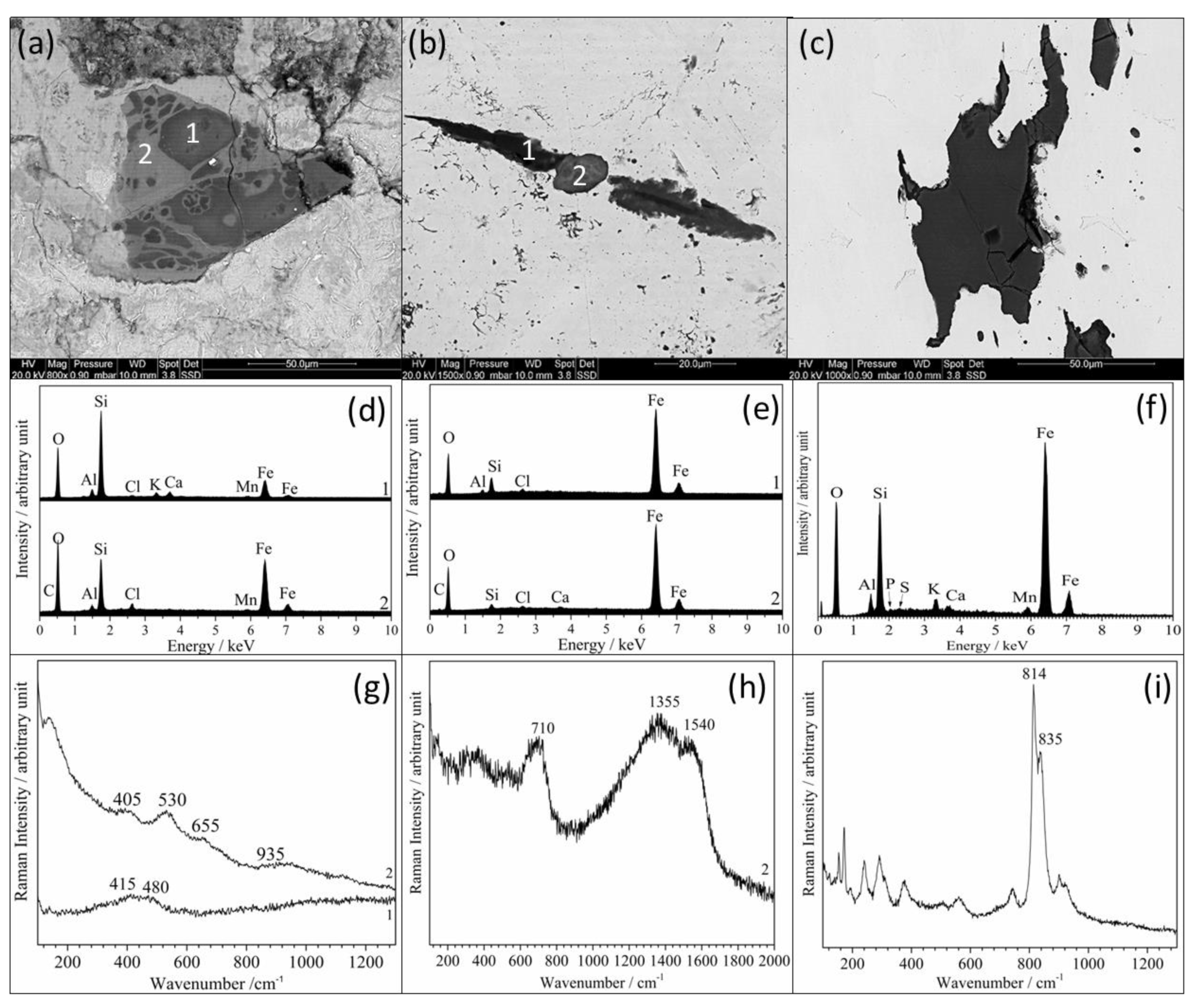
Non-metallic inclusions showed a well-defined spatial distribution along the deformation flow, as observed in each artefact’s section in Figure 3a–c. Examples are displayed in Figure 4, presenting chemical contrast ESEM-BSE micrographs (Figure 4a–c), EDS (Figure 4d–f), and micro-Raman (Figure 4g–i) spectra.
Inclusions of nails OI-260 and OI-262 showed different grey levels in chemical contrast, meaning a multi-phase composition (Figure 4a,b). EDS analysis carried out on an inclusion of the nail OI-260 showed a predominance of oxygen and silicon and a significant peak of iron, as shown in Figure 4d. This suggests that the inclusions of this nail corresponded mainly to iron-containing silicate compounds, the chemical contrast of which is mainly determined by the iron content. The micro-Raman spectrum acquired in the dark area (label 1 and spectrum 1 of Figure 4a,d,g) of the inclusion shows characteristic bands of glass. Spectrum 2, acquired on a lighter area (label 2 on Figure 4a,d,g), corresponds to an iron phyllosilicate [49], resulting probably from the long-term interaction between the glass of the primary inclusion and iron all around it. The micro-Raman spectrum acquired in the middle of the inclusion of sample OI-262 (label 2 of Figure 4b,e,h) shows bands of ferrihydrite (710 cm−1) and of amorphous carbon (1355 and 1540 cm−1). This indicates a high alteration of the inclusion. Silicon is still present but in a very low amount, as shown on the EDS spectrum of Figure 4e. Moreover, the presence of amorphous carbon may be significant for the occurrence of a graphitization process of Fe3C cementite [31] or could be due to the incorporation of a charcoal particle during the forging process. Lastly, inclusions in OI-268 were different (example in Figure 4c). Corresponding also to an iron-containing silicate, micro-Raman spectra clearly identified Fe2SiO4 fayalite (Figure 4f,i). In addition, phosphorus and sulphur were detected only in inclusions of this artefact.

3.3. Microstructural Investigations Using EBSD

EBSD measurements allowed determining characteristic microstructural features of the three samples.
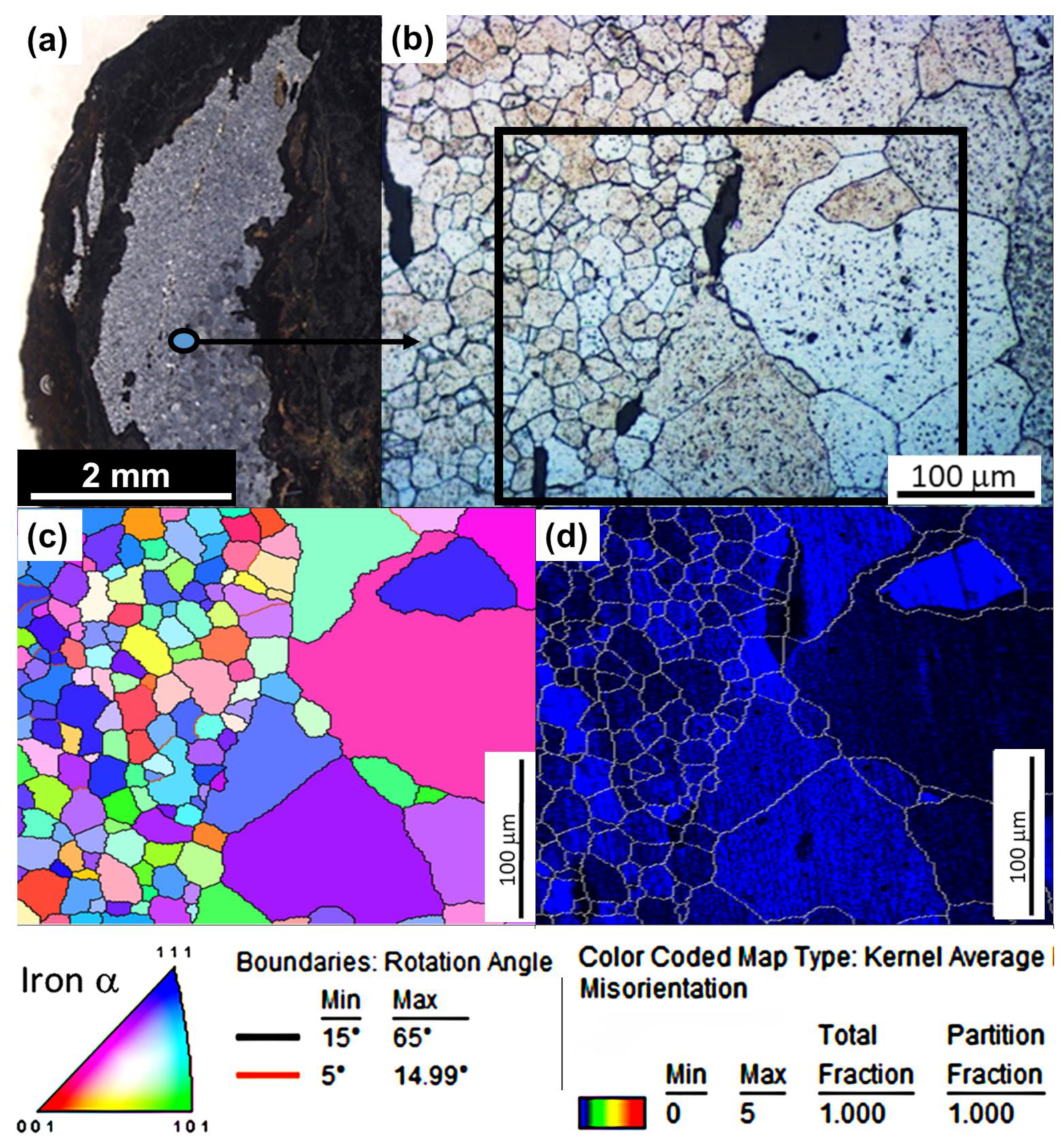
The microstructural study of sample Ol-268 is presented in Figure 5. The ferritic structure was already highlighted by OM (Figure 3f,i). The OM micrograph presented in Figure 5b corresponds to the area studied by EBSD. The scanned zone is delimited by the black rectangle and we can see a good correlation between grains revealed by OM and the EBSD grain maps of α–iron (Figure 5c). Two populations of ferrite grains can be distinguished according to their size and are separated by a line corresponding to a series of inclusions (black grains in Figure 5b). The first population corresponds to small-sized grains (with an average grain size of 20 microns), and the second one to much larger grains (with an average grain size around 100 microns). The EBSD grain inverse pole figure map, by considering the α-iron phase (Figure 5c), shows grains in random colors, whatever their size, meaning that grains have random crystalline orientations with respect to the observation plan. This is characteristic of a polycrystalline microstructure, with no preferential texture. Moreover, each grain presents a uniform color, meaning a single crystalline orientation at the grain scale (Figure 5c). This demonstrates that grains are not deformed. This feature can be more precisely determined by the Kernel Average Misorientation map (KAM map in Figure 5d), highlighting the local densities of geometrically necessary dislocations (GNDs). This representation indicates differences in local deformation. The black to blue color of grains for this sample means that there is no deformation gradient (black) or that this is very weak (blue) at the subgranular scale.
Figure 6 displays one example of results obtained from sample Ol-260 section, under the head of the nail, namely an area supposed to have undergone great stress during the driving of the nail (Figure 6a). Several scans were performed in different areas, the head and tip of the nail, and the same features were observed on the whole section (Supplementary Figure S1 in the Supplementary Materials). The EBSD grain inverse pole figure map by considering only the α-iron phase (Figure 6b) shows grains with size from a few microns to several tens of microns and in random colors, meaning a polycrystalline microstructure without clear preferential orientation. In addition, and unlike sample Ol-268, a color gradient is observed inside grains, which suggests a local gradient of misorientations. This may be due to the strain hardening. This observation was confirmed more locally, as shown in Figure 6c, which corresponds to the zoomed area delimited by the black rectangle in Figure 6b. The non-uniform color indicates a gradient of orientation of the pearlitic ferrite. In fact, all grains of the analyzed areas present this feature, with sometimes a large gradient of orientations as demonstrated in Supplementary Figure S2 in the Supplementary Materials. In this supplementary file, crystallographic orientation diagrams are associated with the EBSD maps of Figure 6 across the width of the tip section and represent the main directions (zone axes, at the extremities of the “triangle”) of the ferrite diffraction space. The presented example shows a gradient of orientations around a particular crystallographic direction, which corresponds here to the red band going from [024] towards [113] zone axes, and indicates a predominance along the (32 1 ¯ ) direction. Because of such deformations at a submicronic scale, the grains have numerous subboundaries of misorientations superior to 5° (violet lines) and sometimes superior to 15° (black lines) (Figure 6d). Moreover, these subboundaries are discontinuous, delimiting no subgrains. Since the object consists of a hypereutectoid alloy with a high content of cementite, a multi-phase map was carried out including ferrite and cementite. The latter is visible only as a few islets in pearlitic ferrite (respectively, green and red color in Figure 6e) instead of lamellas as expected. Either the lamellas were removed by the polishing procedure applied for EBSD measurements or the lamellas are locally too thin to be resolved at 20 kV. However, the trace of the cementite lamella distribution can be observed on the corresponding image quality (IQ) map (Figure 6f). In the analyzed pearlitic area, cementite lamellas are highly curved, unevenly spaced and it can be noticed that intra-grain orientation changes in the direction of pearlitic ferrite (misorientation lower than 5°) occur not necessarily in parallel to the directions of cementite lamellas. They are even sometimes perpendicular to the lamellas’ curvature. The observation of an orientation gradient in the pearlitic ferrite is significant and of high local densities of geometrically necessary dislocations (GNDs) [50], as represented here through the Kernel Average Misorientation (KAM) map in Figure 6g. The green color shows a higher level of grain deformation than observed for sample Ol-268.
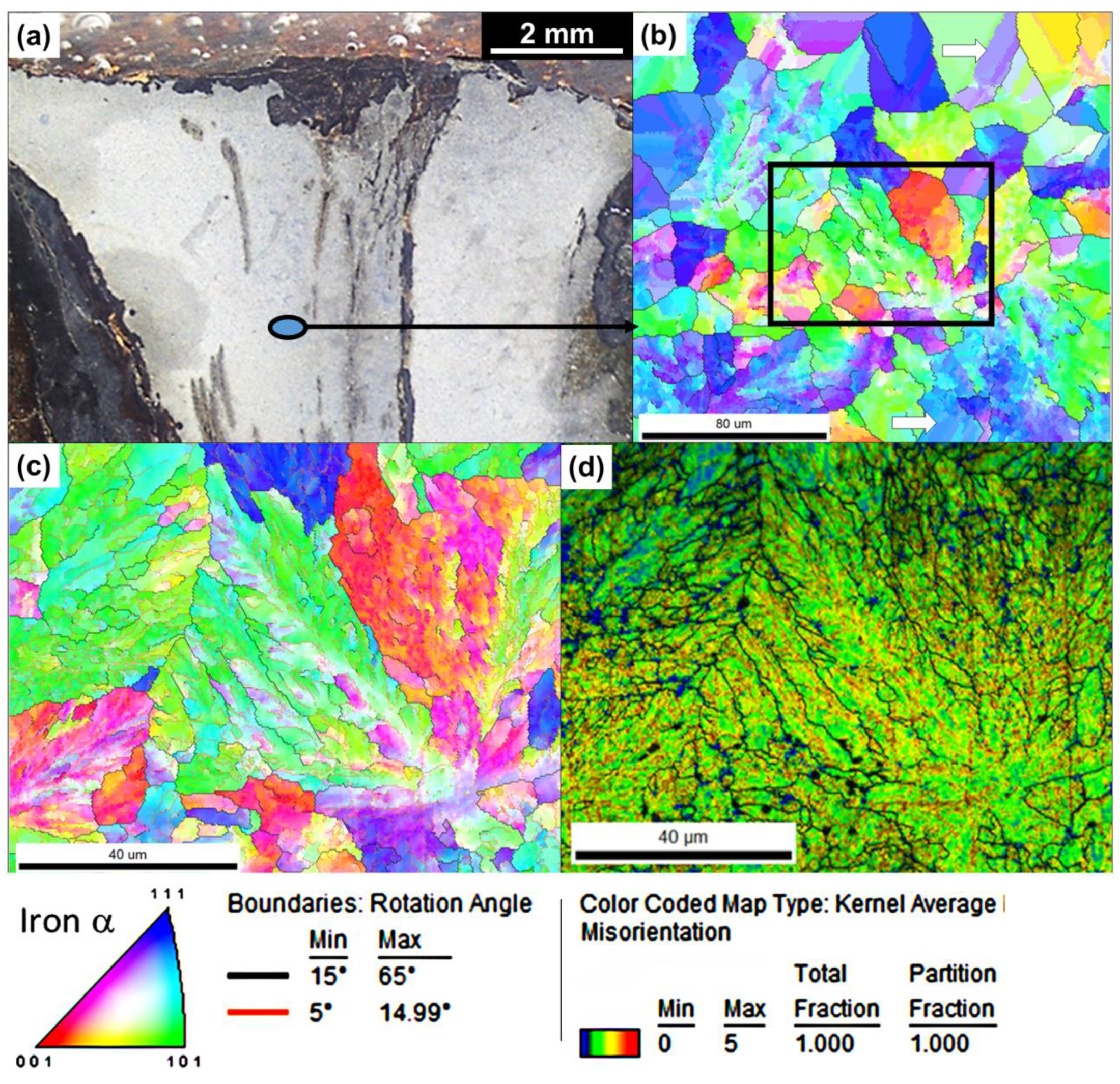
Supplementary Figure S3 in the Supplementary Materials show EBSD measurements performed on different areas of sample Ol-262 section, considering the phase iron α. Figure 7 develops results for one of these (Figure 7a). The grain size is in the 10–50 μm range and the microstructure was attributed to a eutectoid alloy. Several kinds of grains according to their level of deformation can be distinguished on the inverse pole figure (Figure 7b). Highly deformed grains, as those observed for sample Ol-260, are present (Figure 7c) and are here representative of pearlite grains. These show large orientation gradients of the pearlitic ferrite, meaning a large density of GNDs in the pearlitic colonies as shown on the KAM map (Figure 7d). The green to orange color demonstrates that grains are highly deformed in this area, even more than was observed for samples Ol-260 and Ol-268. However, grains with more uniform colors can be seen in Figure 7b. Parallel bands of different colors appear inside these grains (examples indicated by white arrows). This may reveal the presence of twins. It is likely that the deformation of pearlite colonies induces deformation of the neighbouring ferrite grains, leading to such microstructural features.

4. Discussion

The archaeological site Loiola is well known but the local context as well as the conditions of extraction and conservation of the studied objects are not documented. The interpretation therefore relies exclusively on the analytical data. EBSD experiments revealed different kinds of microstructures, two of which are very complex. Samples Ol-260 and Ol-262 pearlite colonies have high defect densities. Curved pearlitic cementite, crystallographic gradients of pearlitic ferrite (probably also of pearlitic cementite) and heterogeneous GND densities generally develop with increasing plastic deformation. In addition, the high content of iron carbide is known to increase the strength of the alloy, which is moreover amplified by a high dislocation density in the pearlitic ferrite. On one hand, as for sample Ol-260 compared to sample Ol-262, EBSD scans showed similar features in different areas of the sections (Supplementary Materials). On the other hand, the microhardness measurements carried out in the middle of the tips of the samples revealed high values. These observations suggest that the microstructure, characterized by a high content of iron carbide, is homogeneous in the whole piece, although no martensite was observed. The absence of martensite could mean slow cooling during the manufacturing process even in the case of tempering. This is also likely to result from annealing operations during object shaping. Lastly, the objects were identified as nails and were probably used; namely, they were driven by hammering to assemble a structure. Since no significant difference in microstructure was revealed in critical zones such as under the head (sample Ol-260), it can be assumed that the hammering had a negligible impact on the microstructure, so that the high strength of these nails was initially intentional. To this purpose, the objects could have been enriched in carbon during the forge work by carburizing using charcoal for annealing, until the desired hardness.
Sample Ol-268 is composed of ferrite and presents an isotropic texture. The microstructure is indicative of a cooling sufficiently slow for the equilibrium phase iron α to be restored from prior austenite and/or annealing operations. However, two populations of grains were highlighted, one corresponding to small-sized grains and one corresponding to large-sized grains. These two populations are not mixed together; they are present in well-delimited zones. This demonstrates that the cooling rate was heterogeneous at the scale of the object. The small-sized grain zones correspond to a cooling, which occurred faster than that in the large-sized grain zones. Such grain size variability could have been caused by partial recrystallization due to annealing when additional shaping was required. On the other hand, the presence of a line of inclusions delimiting clearly the two zones, as observed in Figure 7b, could have had an impact on the heat transfer. This second hypothesis seems more likely. Since most metals are extremely good conductors, such different cooling rates within a single sample could be due to an uneven distribution of impurities.
The microstructure of the alloy and the nature of inclusions in sample Ol-268, which are different from those of both other samples, indicate clearly that this object was manufactured differently. Moreover, due to the severe corrosion of the object, the shape of the remaining part does not allow one to confirm that it was a nail while the nature of the two other artefacts was unambiguous. Sample Ol-268 could be something else, a tool with a specific function implying a ductile material; unfortunately, this is impossible to determine.
It can, moreover, be noticed that the three artefacts showed an important segregation of non-metallic inclusions, which can contribute to weakening the material. This is indeed common in iron artefacts of bloomery origin. Iron with inclusions that was liable to break when hammered was regularly accepted to make nails [51]. This suggests that, considering the function of the three studied artefacts, a high quality alloy was not needed.
This work aimed to explore the potentialities of EBSD for archaeometallurgical issues. This method proved to be a promising tool for highlighting micrometallurgical markers capable of characterizing treatments undergone by metal objects. However, investigations have to be completed via other metallurgical analysis methods. At last, it is imperative to keep in mind that the observed features result both from the treatment undergone during the manufacture of the object but also during its use. An important challenge would be to be able to deconvolve these effects in order to provide insights on ancient blacksmithing practices but also to help understand the function of a forged object when this is not obvious.

5. Conclusions

Through a multi-technique analysis approach, including EBSD and microhardness measurements, different manufacturing processes of archaeological iron artefacts dating from the Roman period were highlighted. Two nails showed a high level of plastic deformation and microstructural defects (GNDs and crystallographic orientation gradient) meaning that to manufacture them, Roman smiths used alloys of high iron carbide content, probably enriched with carbon by carburization to give them the strength and hardness required for their use. A third artefact showed a pure ferritic structure with a very low level of microstructural defects. An alloy with a low carbon content resulting from a high degree of decarburization was used and this object was probably not a nail, unlike its referencing. This probably had another function requiring a more ductile material. So, roman blacksmiths used different forging techniques depending on the function of the piece, demonstrating a high level of skill. Martensite was not observed in any of the samples, meaning that, after heating to a very high temperature, the cooling of objects occurred sufficiently slowly, probably via annealing operations, for iron α ferrite to be restored from prior austenite. Although the three artefacts showed significant non-metallic inclusions as a result of the bloomery process, these inclusions did not affect the structural integrity of the objects.

Supplementary Materials

The following supporting information can be downloaded at: https://www.mdpi.com/article/10.3390/heritage7060150/s1, Figure S1: EBSD crystallographic orientation maps considering iron α (inverse pole figure) performed in different areas of sample Ol-260; Figure S2: Orientations diagrams associated to the EBSD maps acquired at different magnification, showing local orientation gradients of pearlitic ferrite in sample Ol-260. The red band on the diagrams, going from [024] towards [113] zone axes, indicates a predominance along the (32 1 ¯ ) direction; Figure S3: EBSD crystallographic orientation maps considering iron α (inverse pole figure) performed in different areas of sample Ol-262.

Author Contributions

Conceptualization, M.C.Z., L.À.O. and J.J.C.-O.; methodology, C.R., A.O. and E.C.; validation, all; formal analysis, C.R., A.O., E.C. and H.P.-B.; investigation, C.R., A.O., E.C. and H.P.-B.; resources, M.C.Z., C.R., A.O. and E.C.; data curation, C.R. and J.J.C.-O.; writing—original draft preparation, M.C.Z. and C.R.; writing—review and editing, all; visualization, all; supervision, M.C.Z. and C.R.; project administration, M.C.Z.; funding acquisition, M.C.Z., L.À.O., A.A.-O. and C.R. All authors have read and agreed to the published version of the manuscript.

Funding

This study was financially supported by the IT1442-22 project of the Basque Country Government and by La Rochelle University through Incentive Actions Project ACI2018.

Data Availability Statement

The data presented in this study are available on request from the corresponding author due to ethical reasons.

Acknowledgments

H.P. would like to thank the PRE-2019-2-0138 PhD research grant of the Basque Country Government and to the Arkeologi Museoa of Bilbao (Archaeological Museum) to provide the samples for this study. The authors thank the editor and the reviewers for the useful comments and suggestions on ways to improve the manuscript.

Conflicts of Interest

The authors declare no conflicts of interest. The funders had no role in the design of the study; in the collection, analyses, or interpretation of data; in the writing of the manuscript; or in the decision to publish the results.

References

  1. Giumlia-Mair, A.; Maddin, R. The Origins of Iron. In The Civilisation of Iron: From Prehistory to the Third Millennium; Nicodemi, W., Ed.; Edizioni Olivares: Milan, Italy, 2004; pp. 35–61. [Google Scholar]
  2. Godfrey, E.; Van Nie, M. A Germanic ultrahigh carbon steel punch of the Late Roman-Iron Age. J. Archaeol. Sci. 2004, 31, 1117–1125. [Google Scholar] [CrossRef]
  3. Buchwald, V.F. Iron and Steel in Ancient Times; Det Kongelige Danske Videnskabernes Selskab: Copenhagen, Denmark, 2005. [Google Scholar]
  4. Pleiner, R. Iron in Archaeology: Early European Blacksmiths; Archeologický Ústav AV ČR: Praha, Czech Republic, 2006; p. 384. [Google Scholar]
  5. Salem, Y.; Oudbashi, O.; Eid, D. Characterization of the microstructural features and the rust layers of an archaeological iron sword in the Egyptian Museum in Cairo (380–500 A.D.). Herit. Sci. 2019, 7, 19. [Google Scholar] [CrossRef]
  6. Etxezarraga Ortuondo, I. Paleometalurgia del hierro en el País Vasco Cantábrico: Las haizeolak. Un estado de la cuestión. Munibe Antropol. Arkeol. 2004, 56, 87–104. [Google Scholar]
  7. McDonnell, J.G. The Classification of Early Ironworking Slags; Engineering and Physical Sciences; Aston University: Birmingham, UK, 1986. [Google Scholar]
  8. Pleiner, R. Iron in Archaeology: The European Bloomery Smelters; Archeologický Ústav AVČR: Praha, Czech Republic, 2000. [Google Scholar]
  9. Portillo-Blanco, H.; Zuluaga, M.C.; Ortega, L.A.; Alonso-Olazabal, A.; Cepeda-Ocampo, J.J.; Martínez Salcedo, A. Mineralogical Characterization of Slags from the Oiola Site (Biscay Spain) to Assess the Development in Bloomery Iron Smelting Technology from the Roman Period to the Middle Ages. Minerals 2020, 10, 321. [Google Scholar] [CrossRef]
  10. Giumlia-Mair, A.; Maddin, R. Iron Steel in the Roman Period in Late Antiquity. In The Civilisation of Iron: From Prehistory to the Third Millennium; Nicodemi, W., Ed.; Edizioni Olivares: Milan, Italy, 2004; pp. 113–142. [Google Scholar]
  11. Lang, J. Roman iron and steel: A review. Mater. Manuf. Process. 2017, 32, 857–866. [Google Scholar] [CrossRef]
  12. Pense, A.W. Iron through the ages. Mater. Charact. 2000, 45, 353–363. [Google Scholar] [CrossRef]
  13. Pagès, G.; Dillmann, P.; Fluzin, P.; Long, L. A study of the Roman iron bars of Saintes-Maries-de-la-Mer (Bouches-du-Rhône, France). A proposal for a comprehensive metallographic approach. J. Archaeol. Sci. 2011, 38, 1234–1252. [Google Scholar] [CrossRef]
  14. Fluzin, P.; Berranger, M.; Bauvais, S.; Pagès, G.; Dillmann, P. An archaeological archaeometrical approach of ferrous semi-product: A diachronic qualitative typology (VIIth c BC-IInd c, A.D.). In Acta mineraria et metallurgica: Studi in onore di Marco Tizzoni; Tizzoni, C.C., Ed.; Comune di Bergamo: Bergamo, Italy, 2012; pp. 195–204. [Google Scholar]
  15. Ingoglia, C.; Triscari, M.; Sabatino, G. Archaeometallurgy in Messina: Iron slag from a dig at block P, laboratory analyses and interpretation. Mediterr. Archaeol. Archaeom. 2008, 8, 49–60. [Google Scholar]
  16. Starley, D. Determining the Technological Origins of Iron and Steel. J. Archaeol. Sci. 1999, 26, 1127–1133. [Google Scholar] [CrossRef]
  17. Park, J.-S.; Chunag, A.; Gelegdorj, E. A technological transition in Mongolia evident in microstructure, chemical composition and radiocarbon age of cast iron artifacts. J. Archaeol. Sci. 2008, 35, 2465–2470. [Google Scholar] [CrossRef]
  18. Park, J.-S.; Gelegdorj, E.; Chimiddorj, Y.-E. Technological traditions inferred from iron artefacts of the Xiongnu Empire in Mongolia. J. Archaeol. Sci. 2010, 37, 2689–2697. [Google Scholar] [CrossRef]
  19. Park, J.-S. A preliminary study on the role and implication of plate-type iron artifacts in the ancient iron technology of Korea. J. Archaeol. Sci. 2012, 39, 1925–1932. [Google Scholar] [CrossRef]
  20. Rehren, T.; Belgya, T.; Jambon, A.; Káli, G.; Kasztovszky, Z.; Kis, Z.; Kovács, I.; Maróti, B.; Martinón-Torres, M.; Miniaci, G.; et al. 5,000 years old Egyptian iron beads made from hammered meteoritic iron. J. Archaeol. Sci. 2013, 40, 4785–4792. [Google Scholar] [CrossRef]
  21. Cho, N.-C.; Lee, H.-Y.; Lee, J.-G. Microstructure and heat treatment of Early Iron Age cast iron axes excavated from the Sinpung site, Wanju, Jeonbuk, in the Korean Peninsula. Archaeol. Anthropol. Sci. 2019, 11, 2611–2621. [Google Scholar] [CrossRef]
  22. Shotten-Hallel, V.; Ashkenazi, D.; Tal, O. Archaeometallurgical Analysis of Thirteenth-Century Bronze and Iron Construction Implements from the Walls of the Frankish Castle at Arsuf/Arsur. Metallogr. Microstruct. Anal. 2022, 11, 255–280. [Google Scholar] [CrossRef]
  23. Marrocchino, E.; Telloli, C.; Finotti, S.; Facchi, A.; Eftekhari, N.; De Vito, C. Microstructure, Chemistry and Mineralogy Approach for the Diagnostics of Metallic Finds of the Tomba della Biga (Adria, Italy). Appl. Sci. 2022, 12, 11365. [Google Scholar] [CrossRef]
  24. Srivastava, N.; Singh, A.K.; Kanungo, A.K.; Arora, A.; Rajan, K.; Selvakumar, V. Comparative microstructural and elemental analysis of iron artefacts from Kaveri valley archaeological sites. Archaeometry 2023, 65, 1246–1259. [Google Scholar] [CrossRef]
  25. Stewart, J.W.; Charles, J.A.; Wallach, E.R. Iron–phosphorus–carbon system: Part 1—Mechanical properties of low carbon iron–phosphorus alloys. Mater. Sci. Technol. 2000, 16, 275–282. [Google Scholar] [CrossRef]
  26. Thiele, A.; Hošek, J. Estimation of Phosphorus Content in Archaeological Iron Objects by Means of Optical Metallography and Hardness Measurements. Acta Polytech. Hung. 2015, 12, 113–126. [Google Scholar]
  27. Nicodemi, W.; Mapelli, C.; Venturini, R.; Riva, R. Metallurgical Investigations on Two Sword Blades of 7th 3rd Century, B.C. Found in Central Italy. ISIJ Int. 2005, 45, 1358–1367. [Google Scholar] [CrossRef]
  28. Mapelli, C.; Nicodemi, W.; Riva, R.F.; Vedani, M. Analysis of the nails from the roman legionary at Inchtuthil. Steel Res. Int. 2008, 79, 569–576. [Google Scholar] [CrossRef]
  29. Barnett, M.R.; Sullivan, A.; Balasubramaniam, R. Electron backscattering diffraction analysis of an ancient wootz steel blade from central India. Mater. Charact. 2009, 60, 252–260. [Google Scholar] [CrossRef]
  30. Azoulay, I.; Conforto, E.; Refait, P.; Rémazeilles, C. Study of ferrous corrosion products on iron archaeological objects by electron backscattered diffraction (EBSD). Appl. Phys. A 2013, 110, 379–388. [Google Scholar] [CrossRef]
  31. Grevey, A.L.; Vignal, V.; Krawiec, H.; Ozga, P.; Peche-Quilichini, K.; Rivalan, A.; Mazière, F. Microstructure and long-term corrosion of archaeological iron alloy artefacts. Herit. Sci. 2020, 8, 57. [Google Scholar] [CrossRef]
  32. Northover, S.; Northover, J.P. Applications of electron backscatter diffraction (EBSD) in archaeology. In Historical Technology, Materials and Conservation: SEM and Microanalysis; Archetype Publications: London, UK, 2012. [Google Scholar]
  33. Pérez-Arantegui, J.; Larrea, A. Electron backscattering diffraction as a complementary analytical approach to the microstructural characterization of ancient materials by electron microscopy. TrAC Trends Anal. Chem. 2015, 72, 193–201. [Google Scholar] [CrossRef]
  34. Oudriss, A.; Creus, J.; Bouhattate, J.; Conforto, E.; Berziou, C.; Savall, C.; Feaugas, X. Grain size and grain-boundary effects on diffusion and trapping of hydrogen in pure nickel. Acta Mater. 2012, 60, 6814–6828. [Google Scholar] [CrossRef]
  35. Oudriss, A.; Le Guernic, S.; Wang, Z.; Osman Hoch, B.; Bouhattate, J.; Conforto, E.; Zhu, Z.; Li, D.S.; Feaugas, X. Meso-scale anisotropic hydrogen segregation near grain-boundaries in polycrystalline nickel characterized by EBSD/SIMS. Mater. Lett. 2016, 165, 217–222. [Google Scholar] [CrossRef]
  36. Lehto, P. Adaptive domain misorientation approach for the EBSD measurement of deformation induced dislocation sub-structures. Ultramicroscopy 2021, 222, 113203. [Google Scholar] [CrossRef]
  37. Quirós Castillo, J. Golpeando mientras el hierro esté caliente. Paleosiderurgia en el Norte peninsular. Kobie Ser. Anejo 2014, 13, 5–12. [Google Scholar]
  38. Franco Pérez, F.J.; Etxezarraga Ortuondo, I.; Alberdi Lonbide, X. Los orígenes de la tecnología del hierro en el País Vasco: Ferrerías de monte o haizeolak. Kobie. Paleoantropol. 2015, 34, 267–282. [Google Scholar]
  39. Franco Pérez, F.J. Arqueología y Paleosiderurgia Prehidráulica en Bizkaia (Siglos III-XIII). Tras las Huellas de los Antiguos Ferrones, Geografía, Prehistoria y Arqueología; Universidad del País Vasco, Vitoria-Gasteiz: Gasteiz, Spain, 2017; p. 272. [Google Scholar]
  40. García-Mondéjar, J.; Fernández-Mendiola, P.; Agirrezabala, L.; Aranburu, A.; López-Horgue, M.; Iriarte, E.; Martinez de Rituerto, S. El Aptiense-Albiense de la Cuenca Vasco-Cantábrica. In Geología de España; Vera, J.A., Ancochea, A., Sorando, J.P.C., Cortinas, A.B., Carredo, F.B., Eds.; IGME: Madrid, Spain, 2004; pp. 291–296. [Google Scholar]
  41. Gil Crespo, P.P. Las Mineralizaciones de Hierro en el Anticlinal de Bilbao: Mineralogía, Geoquímica y Metalogenia, Mineralogía y Petrología; Universidad del País Vasco: Leioa, Spain, 1991. [Google Scholar]
  42. Gil Crespo, P.P. Introducción a la geología y mineralogía de los yacimientos de hierro de Bilbao. In Historia del Hierro en Bizkaia y su Entorno; Urkitza, X.O.-E., Ingunza, M.E.A., Crespo, P.P.G., Eds.; Universidad del País Vasco (UPV/EHU): Bilbao, Spain, 2016; pp. 19–52. [Google Scholar]
  43. Pereda García, I. La metalurgia prehidráulica del hierro en Bizkaia: El caso de los alrededores del pantano de Oiola (Trapagarán, Bizkaia). Kobie. Paleoantropol. 1992, 20, 109–122. [Google Scholar]
  44. Pereda García, I. Aportación al conocimiento de la metalurgia del hierro en los s. XI-XIII en Bizkaia: El yacimiento de Oiola-IV (Trapagaran-Bizkaia). Kobie. Paleoantropol. 1997, 24, 69–93. [Google Scholar]
  45. Cepeda Ocampo, J.J.; Unzueta Portilla, M. Ferrería romana de Loiola. Arkeoikuska: Investig. Arqueol. 2014, 2014, 249–251. [Google Scholar]
  46. Franco Pérez, F.J.; Gener Moret, M. Early ironwork in Biscay: Survey, excavation, experimentation and materials characterization. An integral study of the mountainside ironworks (ferrerías de monte or “haizeolak”). Mater. Manuf. Process. 2017, 32, 876–884. [Google Scholar] [CrossRef]
  47. Larrazábal Galarza, J. Análisis de muestras siderometalúrgicas procedentes de los yacimientos Oiola II y Oiola IV (Trapagaran, Bizkaia). Kobie. Paleoantropol. 1997, 24, 95–105. [Google Scholar]
  48. Cornacchia, G.; Roberti, R.; Faccoli, M. Characterization and Technological Origin Identification of Ancient Iron Nails. JOM 2020, 72, 3224–3235. [Google Scholar] [CrossRef]
  49. Galai, L.; Marchetti, L.; Miserque, F.; Frugier, P.; Godon, N.; Brackx, E.; Remazeilles, C.; Refait, P. Effect of dissolved Si on the corrosion of iron in deaerated and slightly alkaline solutions (pH ≈ 8.1) at 50 °C. Corros. Sci. 2023, 210, 110790. [Google Scholar] [CrossRef]
  50. Takahashi, T.; Ponge, D.; Raabe, D. Investigation of Orientation Gradients in Pearlite in Hypoeutectoid Steel by use of Orientation Imaging Microscopy. Steel Res. Int. 2007, 78, 38–44. [Google Scholar] [CrossRef]
  51. Lenik, E.J. A study of cast iron nails. Hist. Archaeol. 1977, 11, 45–47. [Google Scholar] [CrossRef]
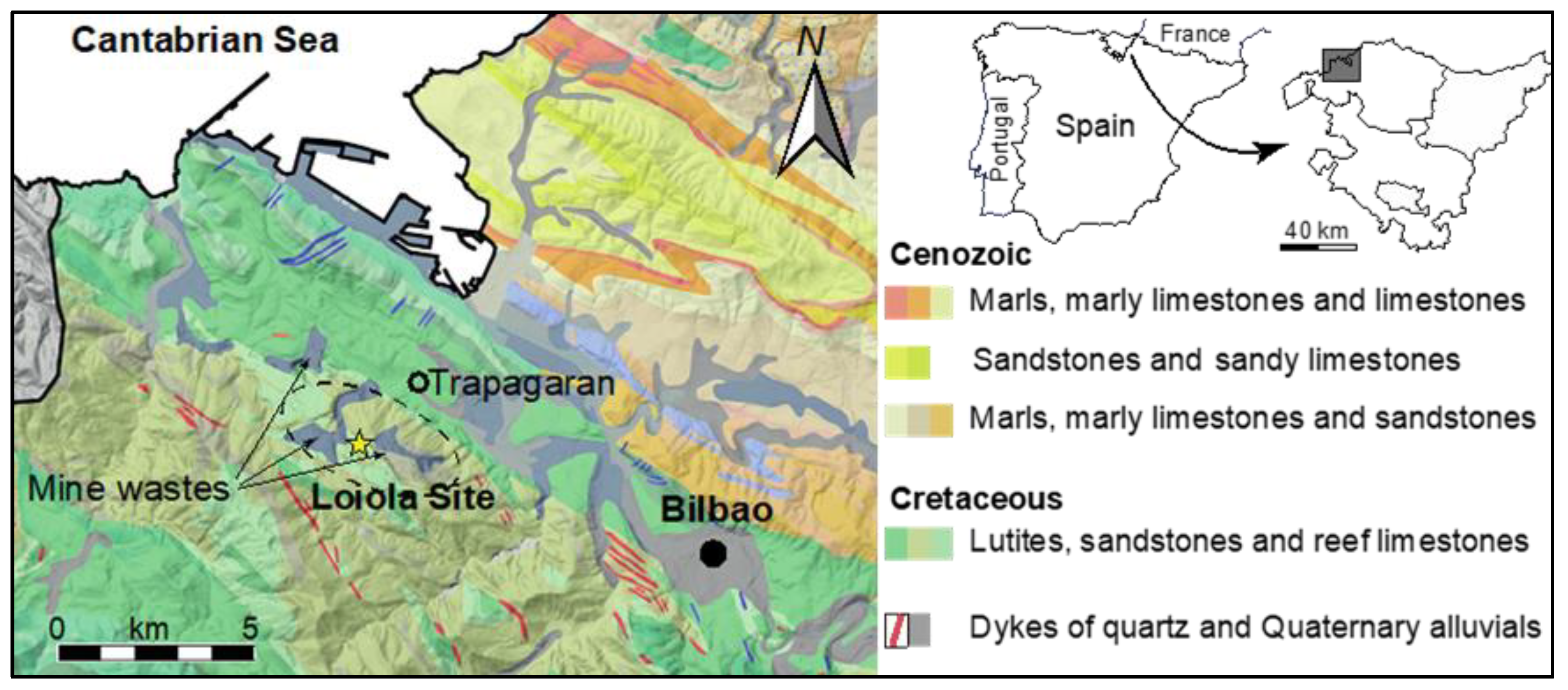
Figure 1. Location of the archaeological site of Loiola on a simplified geological map (corresponding to the grey area on the right map). Dashed lines delimit the mining complex of La Arboleda (Biscay, Spain). Mine wastes from 19th and 20th century mining operations.
Heritage 07 00150 g001
Figure 2. Pictures of the studied iron artefacts.
Heritage 07 00150 g002
Figure 3. General view of sectioned samples OI-260 (a), OI-262 (b), and OI-268 (c). OM micrographs obtained after Nital etching and ESEM micrographs in backscattered electron mode (BSE) of sample OI-260 (d,g), OI-262 (e,h), and OI-268 (f,i). Vickers microhardness measurements of samples OI-260 (j), OI-262 (k), and OI-268 (l) carried out along the red lines represented in (ac).
Heritage 07 00150 g003
Figure 4. SEM-BSE micrographs (ac), EDS spectra (df), and micro-Raman spectra (gi) of representative inclusions in nails OI–260 (a,d,g), OI–262 (b,e,h), and OI–268 (c,f,i).
Heritage 07 00150 g004
Figure 5. (a) Sample Ol-268 analysis areas. (b) OM micrograph, (c) EBSD crystallographic orientation maps for iron α (inverse pole figure) corresponding to the black rectangle in (b), (d) KAM map over the same area of (c).
Heritage 07 00150 g005
Figure 6. (a) Sample Ol-260 analysis area. (b) EBSD crystallographic orientation map considering iron α (inverse pole figure), (c) scan over a smaller area, i.e., detail of scan (b) in the black rectangle, (d) scan over a smaller area, i.e., detail of scan (c) including iron carbide, (e) phase map over the same area of (d), (f) image quality map (IQ) over the same area of (c) showing traces of cementite lamellas, (g) KAM map over the same area of (c).
Heritage 07 00150 g006
Figure 7. (a) Sample Ol-262 analysis area. (b) EBSD crystallographic orientation map for iron α (inverse pole figure), white arrows are examples of twin structures, (c) scan over a smaller area, i.e., detail of scan (b) in the black rectangle, (d) KAM map over the same area of (c).
Heritage 07 00150 g007
Disclaimer/Publisher’s Note: The statements, opinions and data contained in all publications are solely those of the individual author(s) and contributor(s) and not of MDPI and/or the editor(s). MDPI and/or the editor(s) disclaim responsibility for any injury to people or property resulting from any ideas, methods, instructions or products referred to in the content.