Article

A Computationally Assisted Ar I Emission Line Ratio Technique to Infer Electron Energy Distribution and Determine Other Plasma Parameters in Pulsed Low-Temperature Plasma

1
Department of Physics and Astronomy, West Virginia University, Morgantown, WV 26505, USA
2
Sandia National Laboratories, Albuquerque, NM 87185, USA
*
Author to whom correspondence should be addressed.
Plasma 2019, 2(1), 65-76; https://doi.org/10.3390/plasma2010007
Submission received: 11 February 2019 / Revised: 7 March 2019 / Accepted: 14 March 2019 / Published: 21 March 2019
(This article belongs to the Special Issue Latest Developments in Pulsed Low-Temperature Plasmas)

Abstract

:
In the post-transient stage of a 1-Torr pulsed argon discharge, a computationally assisted diagnostic technique is demonstrated for either inferring the electron energy distribution function (EEDF) if the metastable-atom density is known (i.e., measured) or quantitatively determining the metastable-atom density if the EEDF is known. This technique, which can be extended to be applicable to the initial and transient stages of the discharge, is based on the sensitivity of both emission line ratio values to metastable-atom density, on the EEDF, and on correlating the measurements of metastable-atom density, electron density, reduced electric field, and the ratio of emission line pairs (420.1–419.8 nm or 420.1–425.9 nm) for a given expression of the EEDF, as evidenced by the quantitative agreement between the observed emission line ratio and the predicted emission line ratio. Temporal measurement of electron density, metastable-atom density, and reduced electric field are then used to infer the transient behavior of the excitation rates describing electron-atom collision-induced excitation in the pulsed positive column. The changing nature of the EEDF, as it starts off being Druyvesteyn and becomes more Maxwellian later with the increasing electron density, is key to interpreting the correlation and explaining the temporal behavior of the emission line ratio in all stages of the discharge. Similar inferences of electron density and reduced electric field based on readily available diagnostic signatures may also be afforded by this model.

1. Introduction

Experiments and testing facilities can be used in combination with theory, modeling, and simulation to decipher, relate, quantify, and predict in nature the mechanisms that are operating and the processes that are occurring. This combination can extend the ability to document and achieve accuracy in representing variables, conditions, processes, and dynamics well beyond the inference of a physical parameter from a single sensor interpreted with the help of theory. Such a computationally assisted diagnostic technique leads to higher measurement precision and improved process interpretation [1].
Passive optical diagnostics that are non-invasive and non-perturbative, like the 420.1/419.8 nm argon-emission line-height-ratio technique [2,3,4], are desirable because they can be implemented in real time and can be used to determine metastable-atom density [2,5] and effective electron temperature [4]. Emission spectra have been shown to correlate with high energy electrons [2,3,6,7]. The technique described here represents a computationally assisted argon emission line ratio technique to infer electron energy distribution and determine other plasma parameters in pulsed low-temperature plasma.
The 420.1/419.8 nm emission line ratio is suitably sensitive to (neutral) metastable-atom density because the upper state associated with 419.8 nm emission (3p5 in Paschen’s notation or 5p[1/2]0 in Racah’s notation) is populated almost entirely by direct excitation via electron-impact from the ground state while the upper state associated with 420.1 nm emission (3p9 in Paschen’s notation, 5p[5/2]3 in Racah’s notation) is populated both by direct excitation and stepwise excitation via electron-impact from the 1s5 metastable state (4s[3/2]2 in Racah’s notation). The relative efficiency of direct, compared to stepwise, excitation is strongly influenced by the electron energy distribution f(E) because the cross section for direct excitation increases significantly as the effective electron temperature increases, while low energy electrons are mainly responsible for stepwise excitation. For example, the stepwise excitation cross section has its peak near 3 eV, whereas the direct-excitation cross section increases two orders of magnitude from E = 3 eV to E = 10 eV. Note that, regardless of the variation in the direct-excitation cross section with incident electron energy E, the stepwise excitation cross section is still larger by orders of magnitude. The expression for the 420.1/419.8 nm emission line ratio derived previously [2] reflects its direct proportionality to the metastable-atom density for an argon positive column:
R = I 420.1 I 419.8 n 0 k 420.1 0 + n M k 420.1 n 0 k 419.8 1 + n M n 0 k 420.1 k 419.8
where R is the observed 420.1/419.8 nm emission line intensity ratio, I 420.1 and I 419.8 are the observed intensity (W/m2) of 420.1 nm and 419.8 nm emission, n M is the metastable atom density, n 0 is the neutral argon density, k 419.8 is the direct excitation rate from the ground state into the 3p5 state (the upper state for 419.8 nm emission), which is equal in magnitude to the direct excitation rate from the ground state into the 3p9 state (the upper state for 420.1 nm emission) [2,3], and k 420.1 is the stepwise excitation rate from the 1s5 metastable state into the 3p9 state. While the approximations made to obtain the final form expressed by Equation (1) are particular to the neutral argon transitions of interest, emission line pairs for neon, krypton, and xenon with similar sensitivity to the presence of metastable atoms are presented elsewhere [3] and may be used to expand the emission line ratio technique to other noble gases [8].
The utility of the 420.1/419.8 nm emission line ratio has been demonstrated in previous work [2,6]. The proximity of the two lines is an advantage, but the convenience of using closely spaced emission lines becomes a hindrance when expanding diagnostic capabilities to lower-budget or high-throughput laboratories that lack high-resolution spectrometers. Specifically, the advent of the affordable ICCD camera allows for multiple emission lines to be recorded and fully resolved simultaneously—the trade-off being that the wider bandwidth observed comes at the cost of reduced spectroscopic resolution. Replacing the 420.1/419.8 emission line ratio with another emission line ratio that does not require a high-resolution spectroscopic measurement represents an economical alternative for the plasma scientist. In this paper, either emission line pair is treated as an ingredient in a computationally assisted argon emission line ratio technique aimed at inferring electron energy distribution and at determining other plasma parameters in pulsed low-temperature plasma.
To exploit the utility of the 420.1/419.8 nm emission line ratio method, there are some experimental limitations that must be overcome. First, the use of this emission line ratio is limited to those experiments that have sufficient spectroscopic resolution to faithfully implement the method. The spectral lines of interest are separated by only three angstroms requiring a high-resolution spectrometer to suitably sample spectral line intensity at wavelength intervals much smaller than its full-width at half-maximum. Complicating matters, any mechanism that results in emission line broadening imposes a more restrictive resolution requirement, as the broadening causes the emission lines to overlap. An additional limitation in applying this emission line ratio method to high-pressure (P > 10 Torr) discharges is the apparent cross section for excitation to an upper state can be strongly dependent on pressure.
It is with those three limitations of the 420.1/419.8 nm emission line ratio in mind that the substitution of 425.9 nm emission for 419.8 nm emission is noted for making use of an additional 420.1/425.9 nm emission line ratio method. This new emission line ratio relaxes the requirement on spectroscopic resolution by choosing a pair of emission lines separated by over 50 angstroms. To this end, experiments and analysis performed with either line pair have been conducted. We replace the 419.8 nm emission line with the 425.9 nm emission line to quantify direct electron-impact from the ground state, while continuing to use 420.1 nm emission as a measure of metastable density in the plasma [9]. The 425.9 nm emission line is spectroscopically isolated from neighboring lines and comes from the 3p1 upper state (5p’[1/2]0 in Racah’s notation), which has been shown to exhibit less pressure dependence than the 3p5 state that leads to 419.8 nm emission [10]. In this paper, we demonstrate that there are regimes wherein the temporal behavior of 425.9 nm and 419.8 nm emission resemble each other in terms of being sensitive to changes in metastable-atom density, electron density, and reduced electric field. Thus, it may be advantageous for researchers to observe a 420.1/425.9 nm emission line ratio if it can be shown that 419.8 nm emission intensity is equal to 425.9 nm emission intensity in a certain parameter space. In this paper, electron density, metastable density, and reduced electric field are all varied experimentally. The 419.8/425.9 nm emission line ratio was monitored to illustrate when the 420.1/425.9 nm emission line ratio might serve as a useful diagnostic technique. When the 425.9 nm line and the 419.8 nm emission line behave identically, the 425.9 nm emission intensity can be used in place of the 419.8 nm emission intensity in Equation (1).
Wavelengths referenced in this paper (name them by wavelength) were observed with those in agreement.

2. Excitation of 3p States
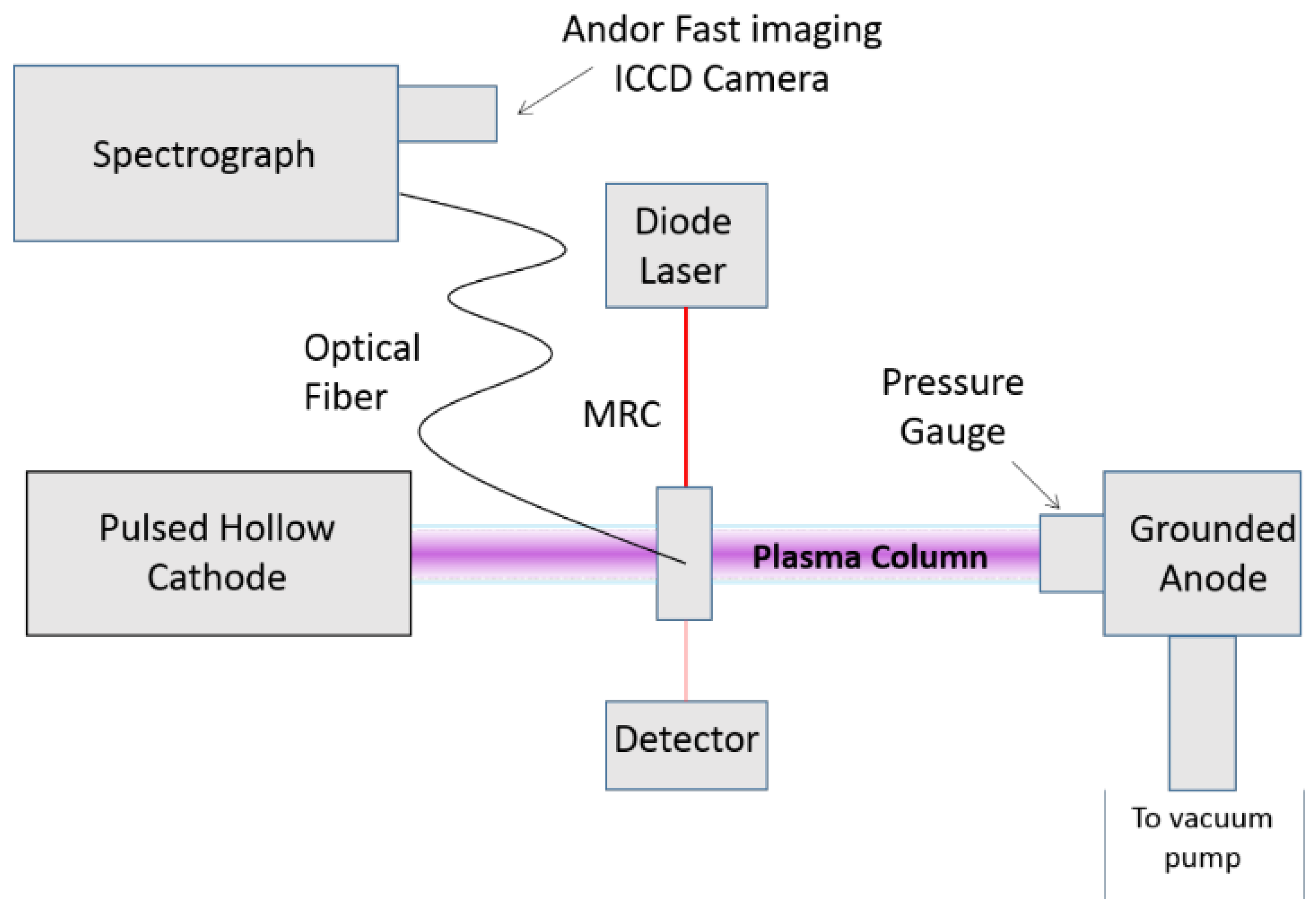
Radiative transitions from the 3p states to the 1s states are responsible for the blue end of the visible emission spectrum of argon. A significant fraction of the 3p population arises due to direct excitation via electron-impact from the ground state, which occurs at a rate:
k i , j 0 = σ i , j 0 2 E m e f ( E ) d E
where σ i , j 0 is the cross section for direct excitation, E is the energy of a colliding electron belonging to the electron energy distribution function, f ( E ) , and m e is the electron mass. The bounds of integration must include all electrons with sufficient energy to excite the transition to state i from the ground state; the lower bound is defined by the minimum energy required for an electron to excite the transition in question and the upper bound is defined by the most-energetic electron in the electron energy distribution function (EEDF). The EEDFs can be measured experimentally as in [5] or evaluated numerically as in [8]. Emission at 419.8 nm, 420.1 nm, and 425.9 nm [11] contains information about plasma parameters and atomic kinetics that can be extracted via emission line ratio techniques [8]. The 420.1/419.8 nm emission line ratio is sensitive to stepwise excitation via the 420.1 nm emission and the presence of metastable atoms: initially R = 1, and the ratio will increase when a sufficient number of metastable atoms are present such that the 3p9 state is populated by both direct and stepwise excitation. The ratio should be less than unity only in the presence of a significant population of high-energy (>30 eV) electrons, as argued in [2,3,6] and shown in [7]. Alternatively, the emission line ratio can be used in combination with the measured metastable atom density (e.g., by tunable diode laser absorption) to determine the EEDF by comparing the measured emission with the predicted emission for different EEDFs.
This work focuses primarily on the relative population of the 3p1 and 3p5 states, which are the upper states for 425.9 nm and 419.8 nm emissions, respectively. The cross sections for excitation to these states are similar in the fact they (1) are zero below approximately E = 13 eV (i.e., electrons with energy below 13 eV have no direct effect on the rate at which the excited states are populated) and (2) have comparable values for incident electron energies above 20 eV. Qualitatively, the cross sections of interest have the same shape for a wide range of incident electron energy; however, the 3p1 cross section is larger than the 3p5 cross section between 13 and 20 eV. Thus, the 425.9/419.8 nm emission line ratio should never be less than unity under ideal conditions and should be expected to be greater than unity when a significant population of electrons with energy between 13 and 20 eV are present. The cross sections for electron-collision induced direct excitation to the upper states of the emission lines studied in this work are reproduced in Figure 1.
In order to properly model the intensity of emission from an excited state, one must consider that the population of an excited state can result from a combination of excitation and relaxation processes. Considering 420.1 nm emission from the 3p9 state for example, the coronal model, which considers only direct excitation via electron-impact from the ground state to the 3p9 state, underestimates the intensity of 420.1 nm emission by over a factor of two. By extending the coronal model to include step-wise excitation via electron-impact from the 1s5 metastable state to the 3p9 excited state, the predicted intensity of 420.1 nm emission matches the observed intensity of emission closely, despite the fact that there is only approximately one metastable argon atom for every 106 ground state argon atoms in the plasma. This dependence on the density of a metastable state introduced by extending the coronal model was key in the development of the emission line ratio method for determining metastable atom density demonstrated in previous work [2]. Examination of the direct and step-wise excitation cross sections and some knowledge of the electron energy distribution can help distinguish the valid regimes for application of the coronal model versus an extended coronal model. Generally, the coronal model is applicable to low-pressure discharges, while the extended coronal model provides a better description for higher pressure discharges [8]. Direct excitation cross sections decrease to zero quickly as the incident electron energy decreases below the onset energy of the excited state of interest, while the stepwise excitation cross sections remain non-zero as the incident electron energy decreases below the excited state energy because metastable atoms are in an excited state (11.5 eV above ground state).
As mentioned above, relaxation processes, or cascade contributions to the population of the excited state of interest, should also be considered. In fact, radiative cascades into a state of interest are accounted for in the apparent excitation cross section (as opposed to the direct excitation cross section that only accounts for excitation to the state of interest from lower energy states). Another option is to use optical emission cross sections that include the branching ratio from selected higher-energy states down into the excited state of interest for the emission line ratio model. The excitation rates used in previous experiments [2,6] were calculated [3] using optical emission cross sections that accounted for the branching ratio as well as cascades into the excited state. The cascade contribution may be accounted for in the high-energy tail of the optical emission cross sections, as a function of pressure, in a procedure outlined in [7].
It is also worth noting that, similar to the dipole selection rules, electron impact excitations follow specific excitation patterns, namely ΔJ = 1, 0; however, J = 0→0 is forbidden. This helps explain why the metastable states may populate the 3p9 state, but would not populate the 3p5 to 3p1 states. The metastable state 1s5 (J = 2) can be easily excited into the 3p9 state (J = 3) but not into the 3p5 or 3p1 states (both J = 0). The second metastable state, 1s3 (J = 0) (4s’[1/2]0 in Racah’s notation), involves negligible coupling to the 3p5 and 3p1 states because the J = 0→0 transition is dipole-forbidden. It is natural to assume that neither the 3p5 nor the 3p1 states (therefore neither the 419.8 nm and 425.9 nm emission lines) are affected by the metastable-atom density of the plasmas.

3. Experiment

The setup, shown in Figure 2, is similar to that described in [2,6]; minor differences will be explained here. The argon positive column is produced by a 20 μs duration and a square wave voltage pulse at 300 Hz provided by a 1.0 kW power supply. The supply is operated in current-limited mode, and experiments were performed for current limits between 2.0 and 10.0 mA. Multiple diagnostics [2,6,13] were employed to sample plasma synchronously at the same position on the cylindrical axis. A hole in the top surface of the microwave resonant cavity was utilized for collection of optical emission and holes in the sides of the cavity provided a line of sight across the plasma column for the diode laser absorption measurement.
Light from the positive column region was collected by a collimator inside the body of the microwave cavity, transmitted via fiber optic, and injected into a 0.5 m Jobin Yvon spectrometer with a 2400 grooves/mm diffraction grating. Spectra were collected by an Andor iStar ICCD camera with a 200 ns gate. The combined dispersion of the spectrometer/ICCD system was better than 0.01 nm per pixel, which was small enough to allow all of the emission lines in question to be resolved fully while, at the same time, the spectral span was large enough to capture the 419.8 nm, 420.1 nm, and 425.9 nm emission lines simultaneously, as shown in Figure 3a. When a 1200 grooves/mm diffraction grating is used in the same system, the 419.8 nm and 420.1 nm emission lines overlap, as shown in Figure 3b.
A tunable diode laser is used to monitor three absorption lines between 790 and 820 nm to determine the densities of three excited states in the plasma: the 1s5 and 1s3 metastable states and the 1s4 resonant state (4s[3/2]1 in Racah’s notation). Radiative transitions from metastable states are dipole-forbidden, so metastable-atom density increases until non-radiative effects (e.g., collisional quenching) dominate and the states are quenched. Radiative transitions from the resonant states to the ground state are allowed. However, due to radiation trapping, the density of the 1s4 resonant state approaches that of the metastable states for the pressure range studied here. Due to the shorter relative lifetime of the resonant state compared to the metastable states, the population decay of the resonant state proceeds quicker.

Microwave Resonant Cavity

Electron density and electron collision frequency were determined by using a microwave cavity operating in TM010 mode. While the details are partially described in previous work [2,13], the principles of operation are reproduced here for clarity. A microwave signal generator drives an antenna placed near the outer-edge of the 5-cm-radius microwave resonant cavity (MRC), and the frequency is varied from 2.0 to 3.2 GHz. The cavity’s resonant frequency (vacuum resonance f0 = 2.02 GHz) increases in the presence of free electrons, abundant in the plasma, according to
Δ f f 0 = 1 2 η ( 1 + γ 2 ) E 0 2 d v / E 0 2 d v = 1 2 η ( 1 + γ 2 )
where Δ f is the shift in resonance frequency, f 0 is the vacuum resonance frequency, η = n e 2 / m ε 0 ω 2 , e is the elementary charge, ε 0 is the permittivity of free space, and γ = ν m / ω where ν m is the momentum transfer collision frequency.
While the magnitude of γ is small and often ignored, the factor is accounted for in this work by measuring the degradation of the cavity quality factor according to
1 Q 1 Q 0 = γ η ( 1 + γ 2 ) E 0 2 d v / E 0 2 d v = γ η ( 1 + γ 2 ) .
Measuring both the shift in the cavity resonant frequency as well as the degradation of the cavity quality factor Q gives us information about electron density and the electron collision frequency in the plasma. Representative data for a 1-Torr discharge with a 20 μs voltage pulse applied at 300 Hz are presented in Figure 4. If the distribution of electrons is assumed to be Maxwellian, the observed collision frequency can be used directly to determine the electron temperature. While this assumption is not necessarily valid for the discharges being analyzed, we present in Figure 4c electron temperature calculated as if it were.
Collision frequency further distinguishes the three stages of the discharge introduced in previous work [2], defined by the slope and magnitude of the 420.1/419.8 nm emission line ratio. The initiation stage is defined by the constant R = 1 emission line ratio (dR/dt = 0) and high collisionality (green squares in Figure 5). The first few microseconds of the discharge are dominated by electron-neutral collisions that depopulate the high-energy tail of the electron distribution via production of 1s5 metastable atoms or (slow) free electrons. When a sufficient population of 1s5 metastable atoms has been generated, we observe a transition into the transient stage of the discharge (blue circles in Figure 5), which is defined by the 420.1/419.8 nm emission line ratio increasing with time (dR/dt > 0). The enhanced 420.1 nm emission, due to stepwise excitation from the 1s5 to the 3p9 state, indicates the presence of metastable atoms. After the emission line ratio increases, it saturates around R = 3 and remains constant for the remainder of the discharge (the post-transient stage). During this stage, the collision frequency is low compared to the initiation stage, as the voltage pulse has sustained the plasma through several collision instances. We find that the three regimes can be distinguished, as shown in Figure 5, across a wide range of discharge current, neutral fill pressure, square-pulse duration, and pulse frequency.
The results from Pack et al. [14] are used to determine the reduced electric field in the argon positive column based on the observed electron drift velocity, which is proportional to the ratio of the plasma current density (measured by high-voltage probe) and electron density (measured by an MRC resonance shift). The reduced electric field and electron density are used in combination with the 420.1/419.8 nm emission line ratio to determine metastable-atom density, as described in [2]. For a more detailed description of the measurement technique, see [2,6,13]. If the metastable atom density is known (e.g., measured via tunable diode laser absorption), Equation (1) shows that the emission line ratio is sensitive to changes in the EEDF through the excitation rates. The ratio of excitation rates in Equation (1) can be calculated as a function of reduced electric field as in [8] for various combinations of ionization fraction and EEDF to generate an effective look-up table. The excitation rate ratio determined from the observed emission line ratio can be compared with a database of calculated excitation rate behavior to determine the most probable EEDF that was present in the experiment.

4. Discussion

Supply current to the hollow cathode was operated between 2.0 and 10.0 mA. Larger values of plasma current within this range correlate with greater electron density, consequently changing the current-voltage characteristic of the plasma. This provides a one-dimensional parameter space, across which the densities of excited species and electrons are varied, to investigate the relative behavior of 425.9 nm emission compared to 419.8 nm emission. A representative example of the observed 425.9/419.8 nm emission line ratio is presented in Figure 6. The qualitative behavior of the emission line ratio indicates the direct correlation predicted in Section 2, that is, the ratio should be constant and only increase in the enhanced presence of a population of electrons in the 13–20 eV range, which could occur as the electron density and temperature begins to stabilize approximately 10 μs into the discharge. However, there is quantitative disagreement, as the ratio is not unity during the initiation stage nor does it exceed unity at any point during the 20 μs discharge. The quantitative disagreement between our predicted behavior of the 425.9/419.8 nm emission line ratio and the observed ratio could be ascribed to uncertainty in the optical emission cross sections (Figure 1). Our prediction was based on the apparent convergence of the cross sections near 13 eV where there are relatively few data points and relatively high slope, increasing the uncertainty of the prediction. This highlights the utility of the computationally assisted aspect of the technique as numerically calculated EEDFs can be used to generate synthetic emission spectra for comparison with the observed emission to determine the observed EEDF.
The 425.9/419.8 nm emission line ratio behaved similarly for all values of discharge current considered in this study, confirming our hypothesis. To reinforce this finding, the double-pulse method described in [15] is implemented in this work to test the robustness of the emission line ratio behavior over a broad range of reduced electric field, electron density, and metastable-atom density. The first pulse in the double-pulse method generates a positive column identical to the discharges already discussed in Section 3 and previous work [2,6]. The second pulse of the double-pulse method is used for control of the species density and/or reduced electric field. The time delay between pulses determines if the second pulse modifies the reduced electric field independent of species densities, as illustrated in Figure 7. The time delay between pulses and the amplitude of the second pulse were systematically varied, and each case was documented to generate a database of accessible species densities and reduced electric fields. That database allows a discharge to be tailored to a desired set of parameters by looking up the corresponding combination of delay between pulses and amplitude of the second pulse.

5. Conclusions

Striking a balance between optimal and practical contributes to identifying the best application of diagnostics. The 420.1/419.8 nm emission line ratio described is an effective diagnostic that requires high-resolution optical emission spectroscopy, which limits its practical implementation in many laboratories. Regarding the proposed alternative of using the 420.1/425.9 nm emission line ratio to remove the requirement for high-resolution spectrometry, the results presented here indicate that success is achievable when careful work is done to implement the new emission line ratio method faithfully.
The first apparent complication is the low-resolution spectrum obtained by a typical 1200 grooves/mm diffraction grating (Figure 3b). The peak of the 420.1 nm emission line will be systematically high, due to the overlap with the 419.8 nm emission line profile; thus, the 420.1/425.9 nm emission line ratio will also be systematically high. The correct 420.1 nm emission intensity is obtained only after subtracting the 419.8 nm emission line profile from the emission signal that results from the overlapped emission line profiles. Motivating this approach, the 425.9 nm emission line mimics closely the 419.8 nm lineshape and is spectrally isolated, providing a ready surrogate of the aforementioned subtraction process.
In this analysis, a pseudo-Voigt profile was used to fit the observed 425.9 nm emission in order to account for various broadening mechanisms associated with Lorentzian or Gaussian emission profiles. The fit to the 425.9 nm emission was multiplied by an amplitude-correction factor based on the observed 425.9/419.8 nm emission line ratio and then subtracted from the emission profile due to overlapping 420.1 nm and 419.8 nm emission. The difference between the overlapped emission profile and the amplitude-corrected pseudo-Voigt profile is the 420.1 nm emission profile that should be used when implementing the 420.1/425.9 nm emission line ratio method.
In practice, the 420.1/425.9 nm emission line ratio method, as presented, lacks precision due to the unpredicted behavior of the 425.9/420.1 nm emission line ratio. This weakness is overcome by numerical calculation of the excitation rates responsible for the production of 425.9 and 420.1 nm emission. The calculated excitation rates can be used in the expression for the emission line ratio (e.g., Equation (1)) in combination with the observed emission line ratio to predict metastable-atom density.

Author Contributions

All authors contributed to all aspects of this research project.

Funding

All authors gratefully acknowledge financial support for this work from the U.S. Department of Energy Office of Fusion Energy Sciences (DE-SC0001939). J.B.F. was partially supported by the U.S. Department of Energy, Office of Science, Office of Workforce Development for Teachers and Scientists, Office of Science Graduate Student Research (SCGSR) program. The SCGSR program is administered by the Oak Ridge Institute for Science and Education (ORISE) for the DOE. ORISE is managed by ORAU under contract number DE-AC05-06OR23100. S.H.N. was partially supported by DOE-SC grant DE-SC0018036. M.E.K. was partially supported by DOE-SC grant DE-SC0012515. The research of V.I.D. has also been partially supported by a National Research Council Research Associateship Award at AFRL and by ITMO Grant No. 713577. E.V.B. was partially supported by Sandia National Laboratories, which is a multi-mission laboratory managed and operated by National Technology and Engineering Solutions of Sandia, LLC., a wholly owned subsidiary of Honeywell International, Inc., for the U.S. Department of Energy’s National Nuclear Security Administration under contract DE-NA-0003525. The APC was funded by MDPI.

Acknowledgments

This collaborative project was carried out under the auspices of the student fellowship program within the DOE Center for Predictive Control of Plasma Kinetics.

Conflicts of Interest

The authors declare no conflict of interest.

References

  1. Koepke, M.E.; Marchand, R. A modelling challenge facility for advancing model and simulation through design of experiments methodology. 2019. in preparation. [Google Scholar]
  2. Franek, J.B.; Nogami, S.H.; Demidov, V.I.; Koepke, M.E.; Barnat, E.V. Correlating metastable-atom density, reduced electric field, and electron energy distribution in the post-transient stage of a 1-Torr argon discharge. Plasma Sources Sci. Technol. 2015, 24, 034009. [Google Scholar] [CrossRef] [Green Version]
  3. Adams, S.F.; Bogdanov, E.A.; Demidov, V.I.; Koepke, M.E.; Kudryavtsev, A.A. Metastable atom and electron density diagnostic in the initial stage of a pulsed discharge in Ar and other rare gases by emission spectroscopy. Phys. Plasmas 2012, 19, 023510. [Google Scholar] [CrossRef]
  4. Boffard, J.B.; Jung, R.O.; Lin, C.C.; Aneskavich, L.E.; Wendt, A.E. Argon 420.1–419.8 nm emission line ratio for measuring plasma effective electron temperatures. J. Phys. D Appl. Phys. 2012, 45, 045201. [Google Scholar] [CrossRef]
  5. Fox-Lyon, N.; Knoll, A.J.; Franek, J.B.; Demidov, V.I.; Godyak, V.A.; Koepke, M.E.; Oehrlein, G.S. Determination of Ar metastable atom densities in Ar and Ar/H2 inductively coupled low-temperature plasmas. J. Phys. D Appl. Phys. 2013, 46, 485202. [Google Scholar] [CrossRef]
  6. Franek, J.B.; Nogami, S.H.; Koepke, M.E.; Demidov, V.I.; Barnat, E.V. Dynamics of atomic kinetics in pulsed positive-column discharge at 100 Pa. Plasma Phys. Control. Fusion 2016, 59, 014005. [Google Scholar] [CrossRef]
  7. Boffard, J.B.; Wang, S.; Lin, C.C.; Wendt, A.E. Detection of fast electrons in pulsed argon inductively-coupled plasmas using the 420.1–419.8 nm emission line pair. Plasma Sources Sci. Technol. 2015, 24, 065005. [Google Scholar] [CrossRef] [Green Version]
  8. Franek, J.B. Correlating metastable atom density, reduced electric field, and electron energy distribution in the initiation, transient, and post-transient stages of a pulsed argon discharge. In Argon Dissertation; West Virginia University: Morgantown, WV, USA, 2017; ProQuest Dissertations and Theses, Publication number: 10276362. [Google Scholar]
  9. DeJoseph, C.A.; Demidov, V.I.; Kudryavtsev, A.A. Modification of a nonlocal electron energy distribution in a bounded plasma. Phys. Rev. E 2005, 72, 036410. [Google Scholar] [CrossRef] [PubMed]
  10. Boffard, J.B.; Chiaro, B.; Weber, T.; Lin, C.C. Electron-impact excitation of argon: Optical emission cross sections in the range of 300–2500 nm. At. Data Nucl. Tables 2007, 93, 831. [Google Scholar] [CrossRef]
  11. Reader, J.; Corliss, C.H.; Wiese, W.L.; Martin, G.A. Wavelengths and Transition Probabilities for Atoms and Atomic Ions, Part I. Wavelengths, Part II. Transition Probabilities. In National Standard Reference Data System, NSRDS-NBS 68; U.S. Government Printing Office: Washington, DC, USA, 1980. [Google Scholar] [CrossRef]
  12. Jung, R.O.; Boffard, J.B.; Anderson, L.W.; Lin, C.C. Excitation into the 3p55p levels from the metastable levels of Ar. Phys. Rev. A 2007, 75, 052707. [Google Scholar] [CrossRef]
  13. Franek, J.B.; Nogami, S.H.; Demidov, V.I.; Koepke, M.E.; Barnat, E.V. Reply to Comment on ‘Correlating metastable-atom density, reduced electric field, and electron energy distribution in the post-transient stage of a 1 Torr argon discharge’. Plasma Sources Sci. Technol. 2016, 25, 038002. [Google Scholar] [CrossRef]
  14. Pack, J.L.; Phelps, A.V. Drift velocities of slow electrons in helium, neon, argon, hydrogen, and nitrogen. Phys. Rev. 1961, 121, 789. [Google Scholar]
  15. Barnat, E.V.; Weatherford, B.R. 2D laser-collision induced fluorescence in low-pressure argon discharges. Plasma Sources Sci. Technol. 2015, 24, 055024. [Google Scholar] [Green Version]
Figure 1. Optical emission cross sections for direct excitation resulting in 419.8 nm (green crosses), 420.1 nm (blue circles), and 425.9 nm (red stars) emissions taken from [12]. Cross sections were obtained from LXcat.
Plasma 02 00007 g001
Figure 2. Experiment located at Sandia National Laboratories, Albuquerque, New Mexico, USA.
Plasma 02 00007 g002
Figure 3. Raw images of the argon spectrum, time-integrated over the entirety of the 20 μs pulse. The image recorded on the CCD is vertically binned to produce the plots. Note the difference in resolution between the top and bottom spectra; in the bottom spectrum, the 419.8 nm emission line overlaps with the 420.1 nm emission line, which complicates the implementation of the 420.1/419.8 nm emission line ratio technique.
Plasma 02 00007 g003
Figure 4. Representative data for a 1 Torr argon positive column generated by 20 μs duration and a square wave voltage pulse at 300 Hz (a current-limited power supply of 7.2 mA for these data). Microwave resonant cavity provides time-resolved measurement of (a) electron density and (b) electron collision frequency, the latter of which is used to determine (c) electron temperature, provided the electron distribution is Maxwellian.
Plasma 02 00007 g004
Figure 5. Three stages of the discharge are distinguished by the collision frequency and change in emission line ratio with respect to time. The initiation stage (the first few microseconds of the discharge) is identified by high collision frequency and constant (in time) emission line ratio R = 1. The transient stage of the discharge was named due to the transient nature of the emission line ratio during the middle stage of the discharge (dR/dt > 0). The collision frequency decreases during the transient stage. The post-transient stage is identified by a constant (in time) emission line ratio R ≈ 3 and low collisionality compared to the initiation stage since the voltage pulse has sustained the discharge for many collision instances by this stage.
Plasma 02 00007 g005
Figure 6. Typical 425.9/419.8 nm emission line ratio for the single-pulse experiments. The observed ratio is not unity during the initiation stage of the discharge but does increase during the discharge.
Plasma 02 00007 g006
Figure 7. The double-pulse method allowed the emission line ratio method to be tested over a wider range of reduced electric field and species densities than the single-pulse discharges allowed. In the left column, the time delay between pulses and the amplitude of the second pulse was chosen such that the reduced electric field and electron density could be reproducibly enhanced at different times in the discharge. The right column demonstrates that reduced electric field can be modified without significant perturbation to the species densities. (a) The plasma is generated by the primary pulse (t = 0 μs) and the discharge is modified by a secondary pulse (examples are shown for secondary pulses that begin at t = 15, 20, and 25 μs). (b) The reduced electric field is modified for the duration of the secondary pulse. (c) The electron density increases when the secondary pulse is applied. (d) The metastable atom density increases when the secondary pulse is applied. (e) The plasma is generated by the primary pulse (t = 0 μs) and the discharge is modified by a secondary pulse at t = 35 μs (examples are shown for three different amplitudes of secondary pulse). (f) The reduced electric field is modified for the duration of the secondary pulse. (g) The electron density is negligibly affected by the secondary pulse. (h) The metastable atom density is negligibly affected by the secondary pulse.
Plasma 02 00007 g007

