Article

Influence of Jointing Methods on the Mechanical Properties of CFRTP Structure Under Bending Load

Department of Systems Innovation, The University of Tokyo, Hongo 7-3-1, Bunkyo-ku, Tokyo 113-8656, Japan
*
Author to whom correspondence should be addressed.
J. Compos. Sci. 2025, 9(6), 291; https://doi.org/10.3390/jcs9060291
Submission received: 18 March 2025 / Revised: 3 June 2025 / Accepted: 4 June 2025 / Published: 6 June 2025
(This article belongs to the Special Issue Mechanical Properties of Composite Materials and Joints)

Abstract

:
Jointing is inevitable for CFRTP (carbon fiber reinforced thermoplastic) component applications in the automotive industry. In this study, commonly used jointing methods were applied to fasten CFRTP components. Three types of jointing methods. Ultrasonic welding, bolted joints, and adhesive joining, and three types of CFRTP materials, conventional cross-ply, ultra-thin prepreg cross-ply, and sheet molding compounds, were selected. The influence of the jointing methods on mechanical properties and damage patterns under bending load has been investigated. The finite element models were developed to predict the hazardous area and structural stiffness of jointed structures; the simulation results showed good agreement with experimental ones. The results indicate that the ultrasonic welding could reach similar bending stiffness compared to adhesive joining, whereas the stiffness of bolt jointed structures is relatively lower due to the contact separation induced by the bending deformation. Overall, the finite element model results correlated well with the experimental data.

1. Introduction

Compared with the traditional carbon fiber reinforced thermosets (CFRTS), the carbon fiber reinforced thermoplastics (CFRTP) show great potential to achieve weight reduction in mass production with a relatively lower cost, benefiting from the easier high-cycle compressive molding capability and better remoldability. Combined with the thermoplastic polymers, discontinuous fiber can extend the advantages of CFRTP to complex shape molding with better formability and realize low-cost recycling and reuse of CFRTP [1]. High-performance discontinuous CFRTP, CFRTP sheet molding compounds (CFRTP-SMC), for instance, have been extensively developed in the past decade and show both good mechanical performance and potentially low cost, but the related research towards applications is still deficient.
Mechanical fastening, welding, and adhesive joining are the most widespread fastening methods in composite structures. Among these fastening methods, mechanical fastening (rivets, bolted joints, and pin-connectors, etc.) owns the advantages of high strength, ease of repairing, and insensitivity to surface temperature or humidity, whereas the redundant weight increment and additional manufacturing process become the demerits of mechanical fastening. The research on the mechanical fastening of composite material started with pin-connectors [2] and extended to bolt and rivet fasteners [3,4,5,6,7,8,9]. Liu et al. presented a modified envelope method for the failure prediction of multi-bolt composite joints. The prediction results were compared with test data, and the results indicate that the method proposed could obtain effective predictions. Olmedo and Santiuste developed a finite element model to predict the effect of secondary bending and tightening torque on the failure of carbon-epoxy composite HTA 7/6376 in single-lap bolted joints. An extension of Chang–Lessard criteria was implemented in the model, and the simulation results showed a good agreement with experimental results. In addition, Davim et al. discussed the damage induced by the drilling process for carbon-epoxy composite, the correlation between the cutting velocity and feed rate with delamination in composite laminate was established through Taguchi’s techniques and analysis of variance (ANOVA). Except for bolted joints, simpler rivets were also investigated by some scholars [8,9].
Except for mechanical fastening, ultrasonic welding is considered a very attractive method for the joining of CFRTP structures among different welding methods, on account of its superior merits like short cycle time, ease of automation, and insensitivity to preliminary treatment [10,11]. Numerous research studies have been conducted to investigate the welding properties of similar [12,13,14] and dissimilar [15,16,17,18] material systems through experimental and numerical methods. In contrast, adhesive joining could overcome the joining limitations of dissimilar material systems. A variety of types of adhesives could be applied according to the required characteristics, such as mechanical properties, thermal conductivities, and sealability. The appropriate adhesive should be selected to achieve the best performance. Owens et al. [19,20] developed a theoretical model to predict the stiffness of adhesively bonded composite/aluminum joints by applying the Adams–Peppiat stress equation, and the model was verified by experimental testing. The results indicate that the joint stiffness and the rate of stiffness loss with crack growth could be accurately predicted by the proposed theoretical model. In addition, hybrid (adhesive/bolted) joints that could combine the merits of different jointing methods were motivated and investigated in recent years [21,22]. Compared to mechanical fastening, welding and adhesive joining could avoid weight increase induced by the fasteners, and reducing the number of fasteners is a research priority in weight-sensitive structures [23].
In this study, the influence of the jointing method on the mechanical properties of CFRTP structures under bending load was investigated. Conventional cross-ply (CP) specimens, ultra-thin (UT) CP specimens, and CFRTP-SMC specimens were jointed by the following different jointing methods: ultrasonic welding (USW), bolted joint (BJ), and adhesive joining (AJ). Three-point bending tests and finite element method (FEM) were performed to investigate the mechanical properties, failure modes and stress distributions of jointed CFRTP structures. The results indicate that the developed FE model could precisely predict structural stiffness, which provides a useful tool to assist with more complicated designs.

2. Materials and Methods
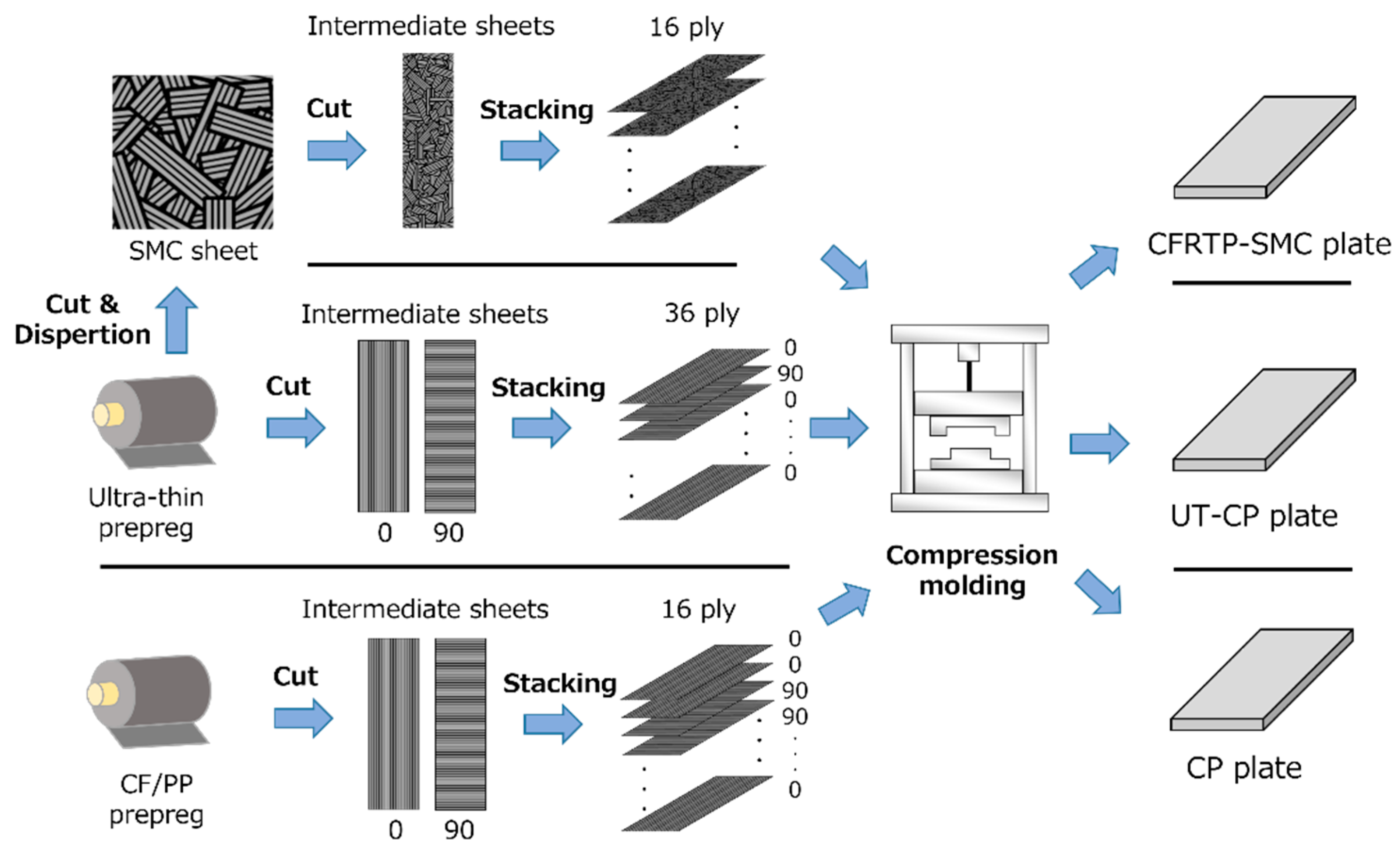
2.1. Materials

To achieve the mass production of automotive structures, three kinds of CFRTP material systems were selected for comparison in this research (Table 1). The manufacturing processes of these materials are shown in Figure 1.
The CFRTP-SMC, also known as ultra-thin chopped carbon fiber tape reinforced thermoplastics, is considered a feasible material for the mass-production automotive industry on account of its outstanding performance on mechanical properties and formability [24]. The CFRTP-SMC is composed of carbon fiber (TR 50S, Mitsubishi Rayon Co., Ltd., Tokyo, Japan) and Polyamide-6 (PA6, Diamiron TM C, Mitsubishi Plastics, Inc., Osaka, Japan) with a volume fraction of 55%. The tape has a size of 18 mm in length, 5 mm in width, and an ultra-thin thickness of 50 µm. Compared to the conventional prepregs with an average thickness of 100 to 150 µm, CFRTP-SMC is superior in suppressing microcracking and delamination damage both in static and dynamic tests [25]. SMC sheets, as illustrated in Figure 1, were fabricated via a wet-dispersion manufacturing process [26,27]; after that, the SMC sheets were trimmed to intermediate sheets with a dimension of 245 mm × 120 mm to fit the mold size. Intermediate sheets were adequately dried with a vacuum dryer (DRV320DA, ADVANTEC, Tokyo, Japan) at 90 °C for 12 h before plate fabrication, and final CFRTP-SMC plates were manufactured with the stacked intermediate sheets through heat-and-cool compression molding; the molding cycle is presented in Figure 2. The materials were input when the mold temperature reached 255 °C, then were pressed under 1 MPa to preheat the material; afterward, molding pressure increased to 5 MPa, and then the temperature started to cool down to 80 °C for plate removal [28].
Compared with a conventional continuous fiber composite, a cross-ply material system with a stacking sequence [0/90]9s was applied. The same ultra-thin prepreg sheet composed of CF/PA6 was used. The ultra-thin cross-ply (UT-CP) plates were also manufactured through a heat-and-cool compression molding cycle, as illustrated in Figure 2.
The third material system is conventional cross-ply (CP) material, which is fabricated from CF/PP prepreg sheets, which are composed of TR50S (TR 50S, Mitsubishi Rayon Co., Ltd., Tokyo, Japan) and polypropylene. The manufactured CP plates have a stacking sequence of [02/902]2s and a fiber volume fraction of 45%.

2.2. Jointing Methods and Specimens

Semi-finished specimens with a rectangular dimension of 60 mm × 25 mm were cut from the obtained plates by diamond disk cutter (AF-500CF), the actual dimensions vary slightly due to the manufacturing scatter, specimen lengths and width were measured by digital calipers (CD67-S PS/PM, Mitutoyo, Kanagawa, Japan), and the thicknesses were measured by digital micrometer (MDC-25-MJ, Mitutoyo, Kanagawa, Japan), the measured dimensions are presented in Table 2.
Ultrasonic welding (USW), bolted joint (BJ), and adhesive joining (AJ) are the most commonly used fastening methods in composite connections. Thus, in this study, semi-finished specimens were connected through these three main fastening methods, as illustrated in Figure 3.

2.2.1. Ultrasonic Welding

Ultrasonic welding is efficient, cheap, and repeatable to process strong and reliable joining with little energy consumption. The welding procedure is illustrated in Figure 3a; two semi-finished specimens were fixed by tape and a toggle clamp on the jig, then the first welding was conducted by an ultrasonic welder (SONOPET Σ/ΣG-2210SL, Seidensha Electronics Co., Ltd., Takasaki, Japan) with a trigger load of 500 N. After that, semi-finished specimens were turned 180° to repeat the previous welding to finish the specimen. To achieve the best welding conditions, several tests were conducted to determine the conditions. The welding surface of CFRTP-SMC with different vibration times is illustrated in Figure 4; it can be observed that the welding surface is fully welded when the vibration time reaches 2 s, while matrix degradation and gasification may be induced and cause low-quality welding. Consequently, a vibration time of 2 s is reasonable for CFRTP-SMC, and the welding conditions are decided with similar methods for UT-CP and CP material systems. Finally, the welding conditions are summarized in Table 3.

2.2.2. Bolted Joint

Bolted joints have the advantages of being simple, easy to disassemble and replace, which makes them widely applied in the real industry. As shown in Figure 3b, three semi-finished specimens were fastened by adhesive tape to keep the relative locations, holes with 4 mm diameter were drilled, after that, steel hexagon socket head cap screws were used to fasten the specimens with a tightening torque of 1.5 N·m.

2.2.3. Adhesive Joining

Adhesive joining has the merits of joining different materials, excellent airtightness, and sealing properties. To apply the adhesive joining method, pretreatment of the surface grinding with sandpaper No. 400# was carefully conducted. After that, the adhesive of Scotch-Weld DP-8010 (3M Japan Limited) was evenly applied on the bonding surface; a primer is not necessary since the adhesive is polyolefin resin. To ensure the adhesive was completely cured, pressure through the thickness direction was applied for one week. The adhesive layers of finished specimens have an average thickness of 0.2 mm, as illustrated in Figure 3c.

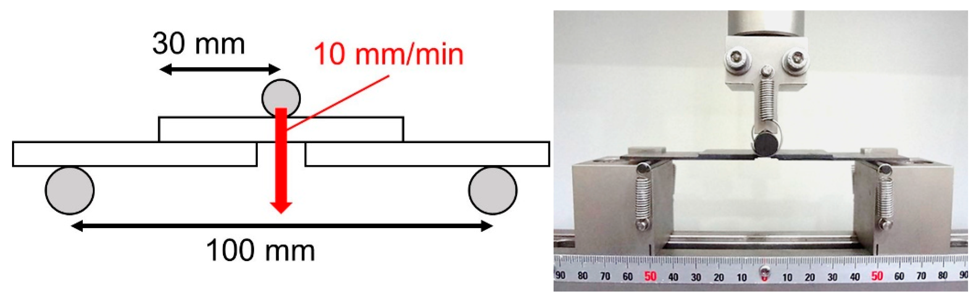
2.3. Experimental Procedure

Schematics of the three-point bending setup are illustrated in Figure 5; the tests were conducted by a table-top universal testing machine (AUTOGRAPH AG-X 5kN, Shimadzu Co., Ltd., Kyoto, Japan), the support span distance is 100 mm, and the displacement speed was equal to 10 mm/min for all specimens during the loading process. Loads and displacements were sampled by the load cell in real-time every 0.1 s until the fracture occurred on the specimens.

2.4. FE Modeling

In the present work, a 3D finite-element model was utilized to verify the structural rigidity and the stress distribution of dangerous areas in different jointing methods. As illustrated in Figure 6, the models were constructed using ABAQUS 6.14 to conduct the analysis; each model consists of three components: the holder, the indenter, and the joining structure. The holder and indenter were modeled by a discrete rigid body according to actual sizes, and joining structures were simulated using Linear 8-node hexahedral brick elements (C3D8R). Each composite ply was assumed to behave as a linearly elastic orthotropic material. The constitutive relation between stress and strain was defined using the stiffness matrix C derived from engineering constants, expressed as follows:
σ 11 σ 22 σ 33 σ 12 σ 13 σ 23 = 1 E 1 ν 21 E 2 ν 31 E 3 0 0 0 ν 12 E 1 1 E 2 ν 32 E 3 0 0 0 ν 13 E 1 ν 23 E 2 1 E 3 0 0 0 0 0 0 1 G 12 0 0 0 0 0 0 1 G 13 0 0 0 0 0 0 1 G 23 1 ε 11 ε 22 ε 33 γ 12 γ 13 γ 23
where E 1 , E 2 , E 3 are Young’s moduli in the principal directions υ i j are Poisson’s ratios, and G 12 , G 13 , G 23 are shear moduli. The values of these engineering constants were either experimentally determined or obtained from the material supplier, as listed in Table 4 and Table 5. Considering the models of different structures, the ultrasonic welding structure was modeled as a whole structure, whereas the adhesive joining structures were modeled with an adhesive layer of 0.2 mm. Concerning bolted joint structure, bolts and plates were modeled separately first, then they were assembled as frictional contact. The implicit solver of Abaqus/Standard was used for the calculation, and nonlinearity caused by large deformation was considered as well during the simulation.

3. Results and Discussion

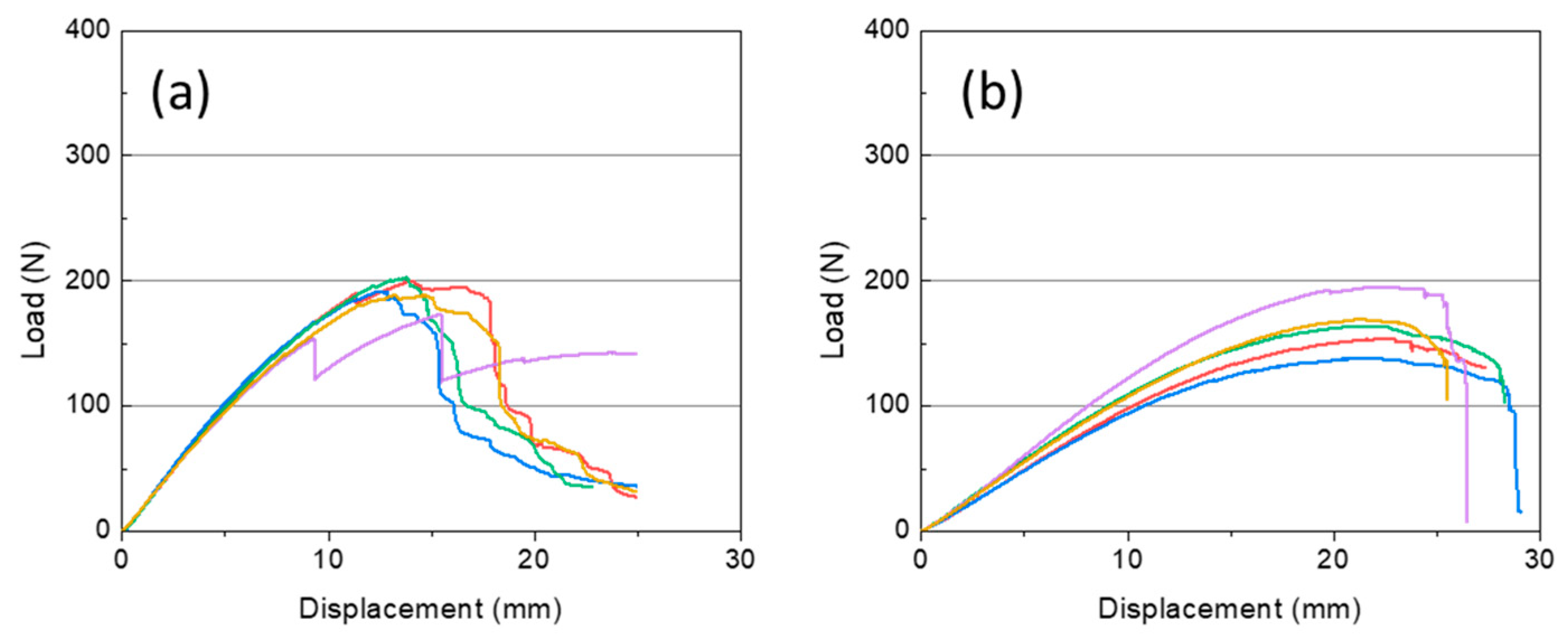
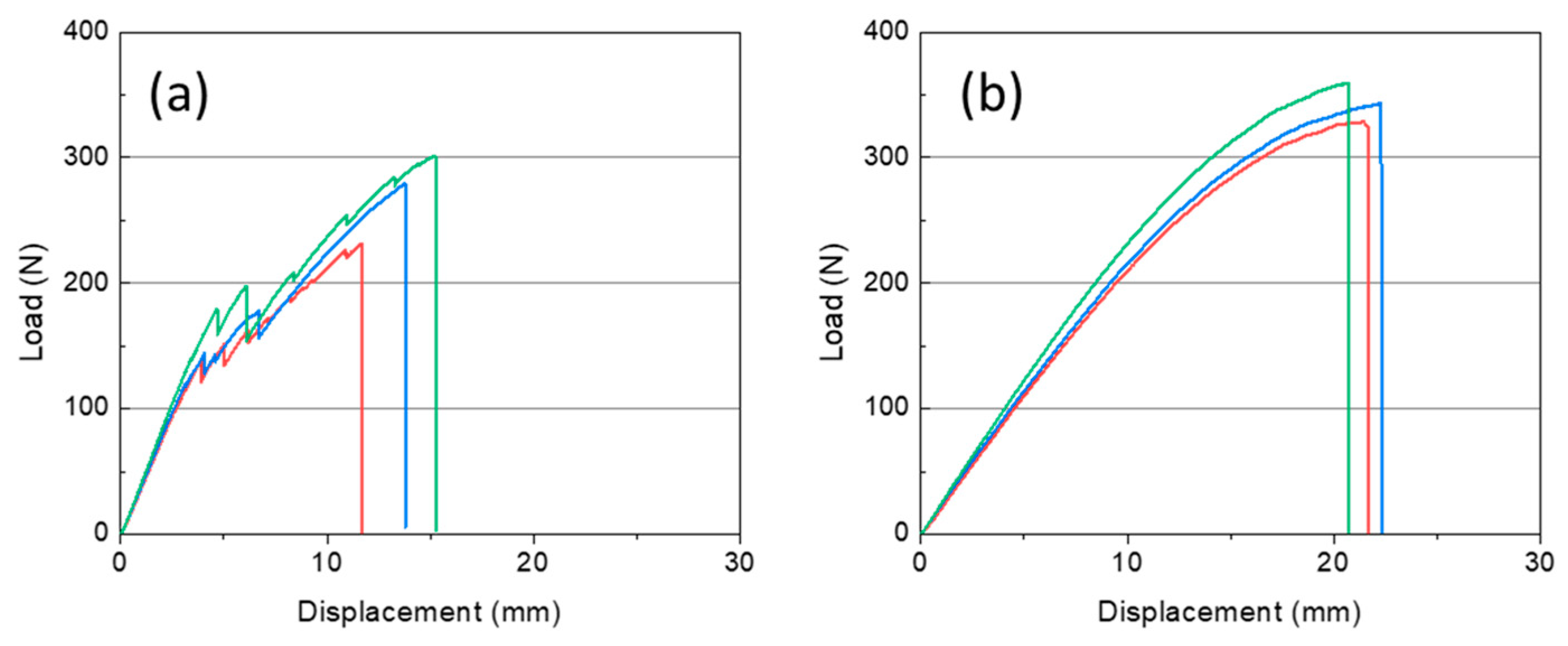
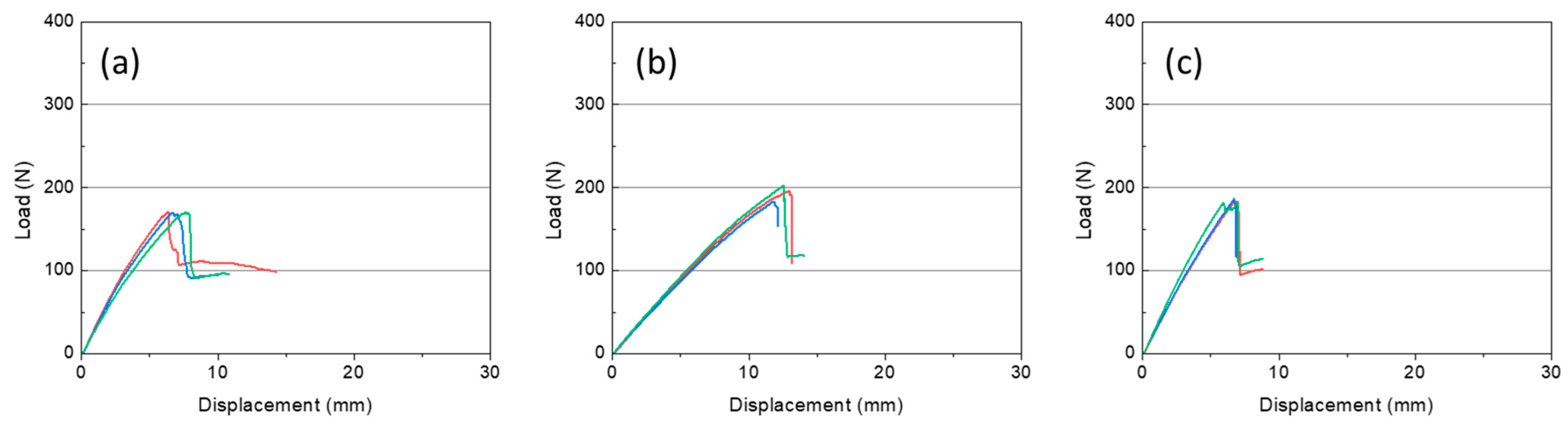
3.1. Three-Point Bending Test

In this study, three-point bending tests with different material systems and jointing methods were conducted; during the loading processes, the load-displacement curves were recorded (Figure 7, Figure 8 and Figure 9), and the specimens were allowed to deform until they reached ultimate failure.
From the load-displacement curves of CFRTP-SMC specimens as illustrated in Figure 7, the load experiences a non-linear increase after initial smooth linear growth, and the failure of the CFRTP-SMC material system is shown as ductile fracture after the peak load in both ultrasonic weldings and bolted joint fastened structures. The maximum loading force was similar with different joining methods since failure modes of USW CFRTP-SMC and BJ CFRTP-SMC were mainly material compressive failure under the indenter, as shown in Figure 10a.
On the other hand, the load-displacement curves of UT-CP and CP material systems are shown in Figure 8 and Figure 9, the failure that occurred in UT-CP and CP material systems are totally shown as brittle fracture regardless of joining method, and the load-displacement curves are shown as a sudden vertical drop when the ultimate load was reached. All the specimens experienced very small individual differences except for USW UT-CP, which is due to the failure mode of USW UT-CP being detachment of the welding part, as shown in Figure 10b, the individual differences of joining parts resulted in the scatter variance of USW UT-CP structures.
Final failure modes were summarized in Table 6, four kinds of failure modes including compressive failure under the indenter, detachment of the welding surface, failure at the washer edge, and compressive failure at the welding edge were observed as shown in Figure 10, and the failure modes for different material systems under different jointing methods are summarized in Table 6. Compared to UT-CP and CP, the CFRTP-SMC specimens exhibited more ductile failure modes under both USW and BJ configurations. This enhanced ductility is attributed to the discontinuous fiber architecture of CFRTP-SMC, which introduces complex internal structures that can impede crack propagation post-initial failure. Additionally, UT-CP demonstrated superior mechanical performance compared to CP under both joining methods, likely due to the thinner prepreg tape in UT-CP promoting a more uniform internal morphology, thereby enhancing mechanical properties through a scale effect.

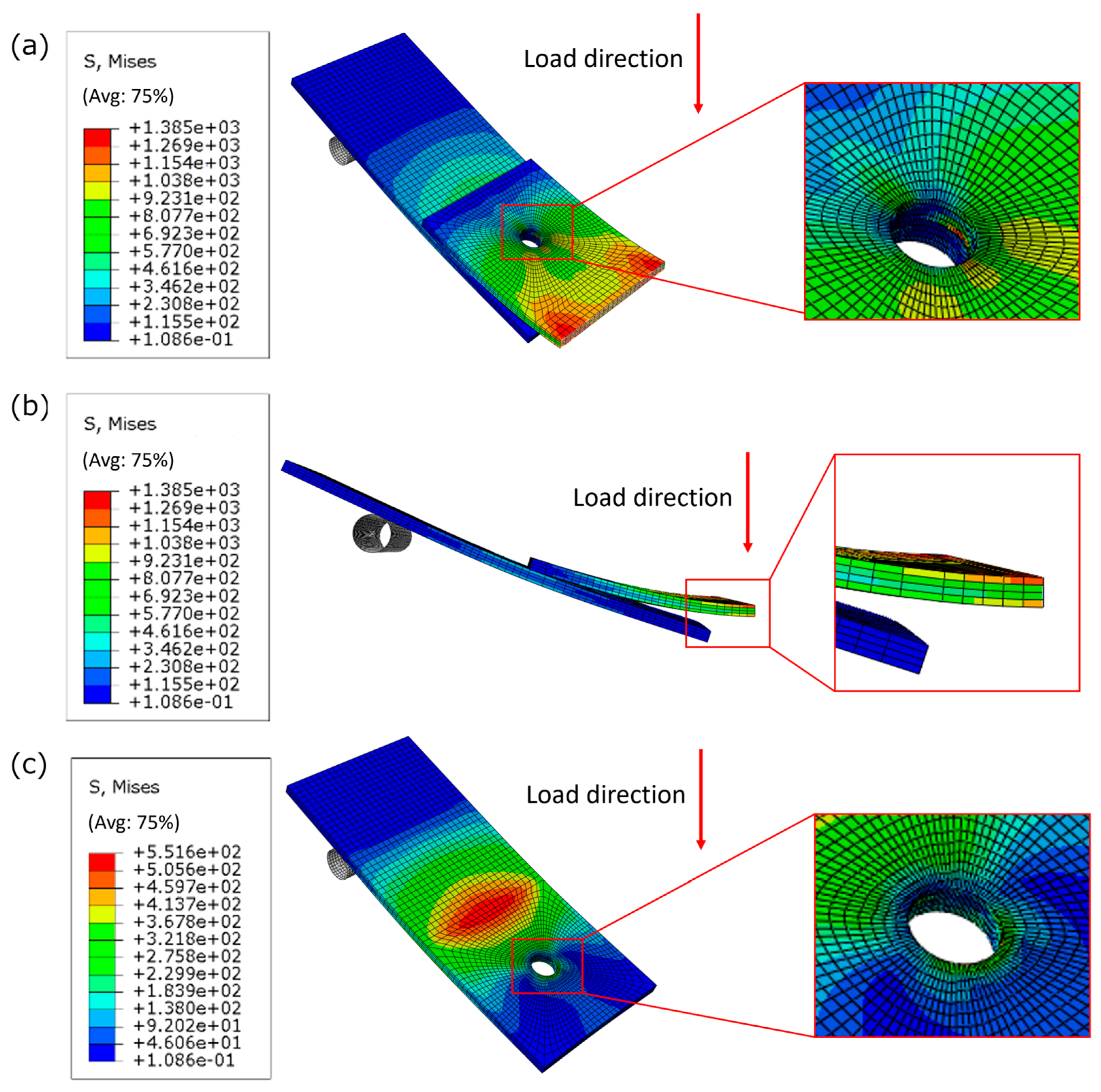
3.2. Finite Element Modeling

3D FEM analyses were conducted to evaluate the stress distribution in the CFRTP structures with the following different jointing methods: USW, BJ and AJ, and the hazardous area was demonstrated through the stress distribution contour. Additionally, stiffness analysis was conducted to predict structural stiffness, and the results agreed well with the experimental results. Three types of CFRTP material systems with different jointing methods were tested, seven cases in total. Only the simulation results of CP structures will be illustrated as representative cases since the other cases with different material systems showed similar stress distributions.
The stress distribution contour of USW and AJ composite structures at maximum bending load is shown in Figure 11. The simulation results indicate that the stress distributions of USW and AJ composite structures under bending load are similar to each other; the upper plate sustains severe compressive stress at the upper surface layer and tensile stress at the lower surface. Moreover, the edge of the joining surface between the upper and lower plate shows intense stress concentration as illustrated in Figure 11c, especially for the USW structures. Three main failure modes were observed for USW and CP composite: (a) compressive failure under the indenter, (b) the detachment of the welding surface, and (c) compressive failure at the welding edge. Among these three kinds of failure modes, material failure under compressive failure under indenter was preferred since the material properties were not limited by the jointing properties. The FEM results accurately predicted the hazardous areas, which are consistent with failure modes that occurred in the experimental tests. Stress concentration in joining edge of USW structures is more severe than AJ structures as FEM results indicated, which accounted for the failure at welding edge and welding surface in USW specimens satisfactorily.
For the case of BJ CP, the stress distribution contour is illustrated in Figure 12. Similar to the USW and AJ cases, we found that the maximum stress is distributed at the center of the upper plate, which indicates that the upper composite plate had to withstand severe compressive strength at the upper surface layer and tensile strength at the lower surface. Besides, the whole edge of the inner side also shows enormous stress concentration, which is induced by the contact between the washer edge and the upper composite plate with the increase of bending deformation. The hazardous area presented by FEM results agreed well with the experimental failure modes: (a) compressive failure the under indenter and (b) failure at the washer edge. Additionally, the separation between the upper and lower composite plates could be observed, which led to the center side of the lower plate not contributing to the mechanical properties of the whole structure. As a result, the lower plate could not contribute to the section modulus in bending as the USW and AJ did; this explained why the stiffness of BJ is obviously lower than that of USW and AJ composite structures, as shown in Figure 7, Figure 8 and Figure 9. Thus, the location of the hole will apparently influence the mechanical properties of the BJ structures because of the integrity variations, which is a significant parameter that needs to be properly designed in real engineering structures to achieve the best mechanical performance; FE method was demonstrated to be a useful tool to provide accurate information for structural design.
The rigidity of various material systems with different jointing methods was compared, as shown in Figure 13. The AJ structure showed a slightly higher rigidity than the USW structure in the CP specimens due to the slight increase in structure thickness on account of the adhesive layer. On the other hand, the USW structure still shows the advantage of high-speed welding and self-adhesion compared to AJ and BJ because the materials were melted and bonded by themselves. The rigidity of the BJ structure is obviously lower than that of USW structures in all the materials because of the separation of the upper and lower plates, as described in the previous section. Besides, comparing with FEM and experimental results, the results of BJ structures were predicted more precisely than USW and AJ structures, which could be attributed to the differences between real welding surface and simplified FE model. However, the FEM values agreed well with the experimental ones overall, which demonstrated FEM could be a useful tool for mechanical properties prediction to aid more complicated structure design in engineering applications.

4. Conclusions

In this study, the influence of the jointing method (USW, BJ, and AJ) on the mechanical properties of CFRTP structures under bending load was investigated experimentally and numerically. The following conclusions can be drawn:
  • Ultrasonic welding (USW) and adhesive joining (AJ) composite structures could reach similar rigidity under bending load in CP specimens; the small variance could be attributed to the thickness increment induced by the adhesive layer. Besides, the rigidity of the bolted joint (BJ) structure is much lower than USW and AJ, which is due to the separation of composite plates induced by bending deformation.
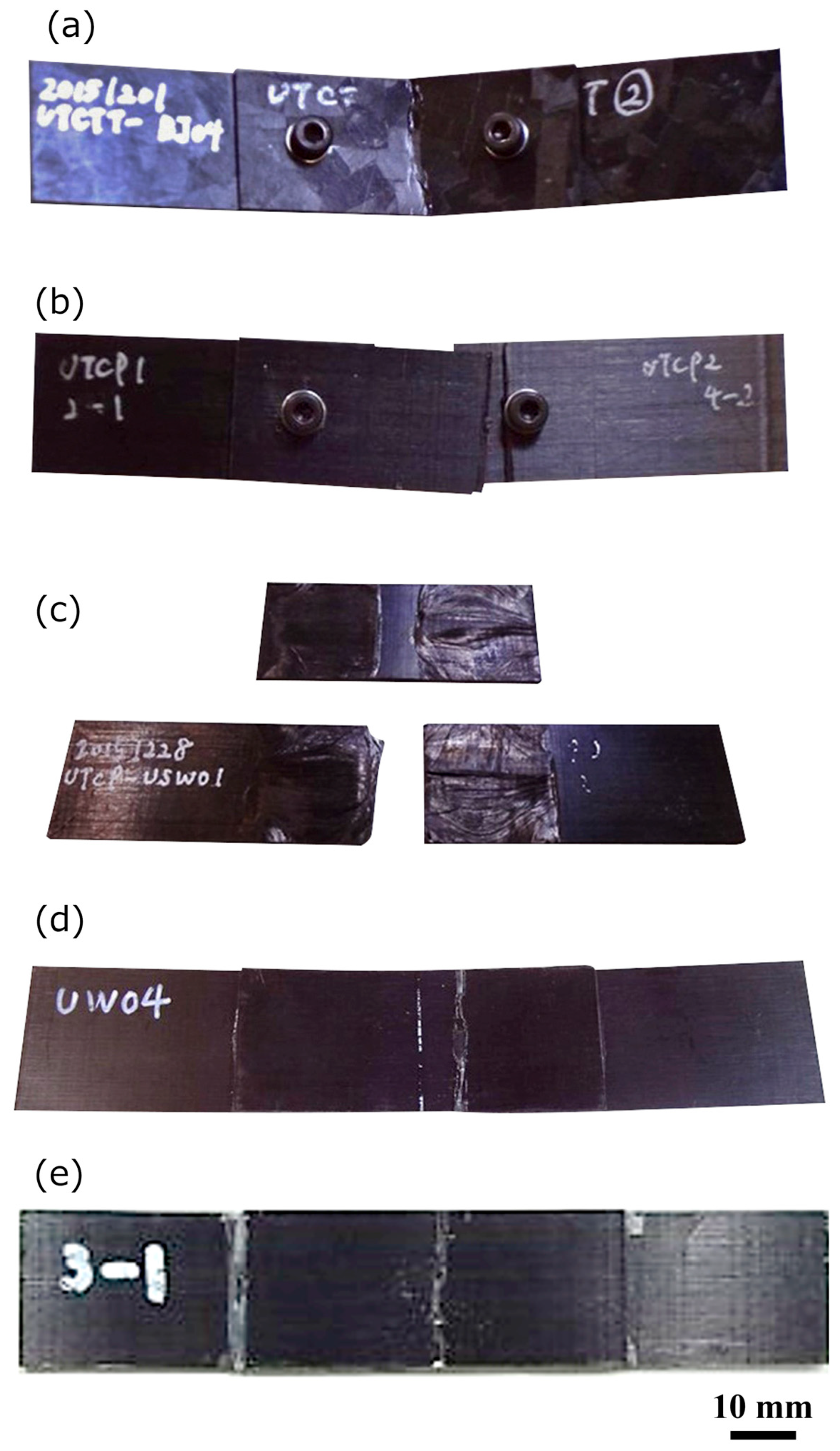
  • The main damage patterns of jointed CFRTP structures under bending load include compressive failure under the indenter, detachment of the welding surface, failure at the washer edge, and compressive failure at the welding edge. Material failure or compressive failure under the indenter was the preferred failure mode since the material properties were not limited by the jointing properties; therefore, the failure of a jointing part should be avoided in structure design to achieve the best structural performance.
  • The materials used in this study were aimed at being applied in the mass-production automotive industry. The hazardous area and bending rigidity could be precisely predicted by the FE model with regard to the CFRTP structures with different jointing methods. The FE method was demonstrated to be a useful tool to provide assistance for more complicated composite structure design.

Author Contributions

Y.W.: Conceptualization, Methodology, Validation, Formal analysis, Writing—Original Draft, Writing—Review & Editing. L.M.: Conceptualization, Methodology, Validation, Formal analysis, Writing—Original Draft, Writing—Review & Editing. H.W.: Conceptualization, Methodology, Validation, Writing—Review & Editing. J.T.: Supervision, Project administration, Writing—Review & Editing. All authors have read and agreed to the published version of the manuscript.

Funding

This research received no external funding.

Data Availability Statement

The raw data supporting the conclusions of this article will be made available by the authors on request.

Conflicts of Interest

The authors declare no conflict of interest.

References

  1. Ishikawa, T.; Amaoka, K.; Masubuchi, Y.; Yamamoto, T.; Yamanaka, A.; Arai, M.; Takahashi, J. Overview of automotive structural composites technology developments in Japan. Compos. Sci. Technol. 2018, 155, 221–246. [Google Scholar] [CrossRef]
  2. Crews, J.H., Jr.; Hong, C.S.; Raju, I.S. Stress-Concentration Factors for Finite Orthotropic Laminates with a Pin-Loaded Hole; NASA-TP-1862; National Aeronautics and Space Administration Hampton Va Langley Research: Hampton, VA, USA, 1981. [Google Scholar]
  3. Smith, P.A.; Pascoe, K.J.; Polak, C.; Stroud, D.O. The behaviour of single-lap bolted joints in CFRP laminates. Compos. Struct. 1986, 6, 41–55. [Google Scholar] [CrossRef]
  4. Hart-Smith, L.J. Bolted Joints in Graphite-Epoxy Composites; Douglas Aircraft Co., Inc.: Long Beach, CA, USA, 1976. [Google Scholar]
  5. Liu, F.; Zhao, L.; Mehmood, S.; Zhang, J.; Fei, B. A modified failure envelope method for failure prediction of multi-bolt composite joints. Compos. Sci. Technol. 2013, 83, 54–63. [Google Scholar] [CrossRef]
  6. Olmedo, Á.; Santiuste, C. On the prediction of bolted single-lap composite joints. Compos. Struct. 2012, 94, 2110–2117. [Google Scholar] [CrossRef]
  7. Davim, J.P.; Reis, P. Study of delamination in drilling carbon fiber reinforced plastics (CFRP) using design experiments. Compos. Struct. 2003, 59, 481–487. [Google Scholar] [CrossRef]
  8. Ueda, M.; Miyake, S.; Hasegawa, H.; Hirano, Y. Instantaneous mechanical fastening of quasi-isotropic CFRP laminates by a self-piercing rivet. Compos. Struct. 2012, 94, 3388–3393. [Google Scholar] [CrossRef]
  9. Song, M.H.; Kweon, J.H.; Kim, S.K.; Kim, C.; Lee, T.J.; Choi, S.M.; Seong, M.S. An experimental study on the failure of carbon/epoxy single lap riveted joints after thermal exposure. Compos. Struct. 2008, 86, 125–134. [Google Scholar] [CrossRef]
  10. Lionetto, F.; Morillas, M.N.; Pappadà, S.; Buccoliero, G.; Villegas, I.F.; Maffezzoli, A. Hybrid welding of carbon-fiber reinforced epoxy based composites. Compos. Part. A Appl. Sci. Manuf. 2018, 104, 32–40. [Google Scholar] [CrossRef]
  11. Dell’Anna, R.; Lionetto, F.; Montagna, F.; Maffezzoli, A. Lay-up and consolidation of a composite pipe by in situ ultrasonic welding of a thermoplastic matrix composite tape. Materials 2018, 11, 786. [Google Scholar] [CrossRef]
  12. Levy, A.; Le Corre, S.; Villegas, I.F. Modeling of the heating phenomena in ultrasonic welding of thermoplastic composites with flat energy directors. J. Mater. Process Technol. 2014, 214, 1361–1371. [Google Scholar] [CrossRef]
  13. Levy, A.; Le Corre, S.; Poitou, A. Ultrasonic welding of thermoplastic composites: A numerical analysis at the mesoscopic scale relating processing parameters, flow of polymer and quality of adhesion. Int. J. Mater. Form. 2014, 7, 39–51. [Google Scholar] [CrossRef]
  14. Palardy, G.; Shi, H.; Levy, A.; Le Corre, S.; Villegas, I.F. A study on amplitude transmission in ultrasonic welding of thermoplastic composites. Compos. Part. A Appl. Sci. Manuf. 2018, 113, 339–349. [Google Scholar] [CrossRef]
  15. Krüger, S.; Wagner, G.; Eifler, D. Ultrasonic welding of metal/composite joints. Adv. Eng. Mater. 2004, 6, 157–159. [Google Scholar] [CrossRef]
  16. Kicukov, E.; Gursel, A. Ultrasonic welding of dissimilar materials: A review. Period Eng. Nat. Sci. 2015, 3. [Google Scholar] [CrossRef]
  17. Bhudolia, S.K.; Gohel, G.; Leong, K.F.; Islam, A. Advances in Ultrasonic Welding of Thermoplastic Composites: A Review. Materials 2020, 13, 1284. [Google Scholar] [CrossRef]
  18. Balle, F.; Huxhold, S.; Wagner, G.; Eifler, D. Damage monitoring of ultrasonically welded aluminum/CFRP-joints by electrical resistance measurements. Procedia Eng. 2011, 10, 433–438. [Google Scholar] [CrossRef]
  19. Owens, J.F.P.; Lee-Sullivan, P. Stiffness behaviour due to fracture in adhesively bonded composite-to-aluminum joints I. Theoretical model. Int. J. Adhes. Adhes. 2000, 20, 39–45. [Google Scholar] [CrossRef]
  20. Owens, J.F.P.; Lee-Sullivan, P. Stiffness behaviour due to fracture in adhesively bonded composite-to-aluminum joints II. Experimental. Int. J. Adhes. Adhes. 2000, 20, 47–58. [Google Scholar] [CrossRef]
  21. Kelly, G. Load transfer in hybrid (bonded/bolted) composite single-lap joints. Compos. Struct. 2005, 69, 35–43. [Google Scholar] [CrossRef]
  22. Camanho, P.P.; Tavares, C.M.L.; De Oliveira, R.; Marques, A.T.; Ferreira, A.J.M. Increasing the efficiency of composite single-shear lap joints using bonded inserts. Compos. Part B Eng. 2005, 36, 372–383. [Google Scholar] [CrossRef]
  23. Kweon, J.-H.; Jung, J.-W.; Kim, T.-H.; Choi, J.-H.; Kim, D.-H. Failure of carbon composite-to-aluminum joints with combined mechanical fastening and adhesive bonding. Compos. Struct. 2006, 75, 192–198. [Google Scholar] [CrossRef]
  24. Selezneva, M.; Lessard, L. Characterization of mechanical properties of randomly oriented strand thermoplastic composites. J. Compos. Mater. 2016, 50, 2833–2851. [Google Scholar] [CrossRef]
  25. Sihn, S.; Kim, R.Y.; Kawabe, K.; Tsai, S.W. Experimental studies of thin-ply laminated composites. Compos. Sci. Technol. 2007, 67, 996–1008. [Google Scholar] [CrossRef]
  26. Meng, L.; Wan, Y.; Ohsawa, I.; Takahashi, J. Effects of geometric parameters on the failure behavior of mechanically fastened chopped carbon fiber tape reinforced thermoplastics. Compos. Struct. 2019, 229, 111475. [Google Scholar] [CrossRef]
  27. Meng, L.; Wataki, H.; Ohsawa, I.; Takahashi, J. Failure analysis of ultra-thin chopped carbon fiber tape reinforced thermoplastic in mechanical joints. In Proceedings of the 17th European Conference on Composite Materials, Munich, Germany, 26–30 June 2016. [Google Scholar]
  28. Wataki, H.; Hayashi, T.; Ohori, T.; Takahashi, J. Flexural property of jointed structure made by CFRTP. In Proceedings of the 14th JAPAN International SAMPE Symposium and Exhibition, Ishikawa, Japan, 6–9 December 2015. [Google Scholar]
Figure 1. Overview of the manufacturing process.
Jcs 09 00291 g001
Figure 2. Molding processes of the plates.
Jcs 09 00291 g002
Figure 3. (a) Ultrasonic welding, (b) Bolted joint, and (c) Adhesive joining.
Jcs 09 00291 g003
Figure 4. The welding surface (red boxes) of CFRTP-SMC specimens with different vibration times: (a) 1.0 s, (b) 1.2 s, (c) 1.5 s, (d) 2.0 s.
Jcs 09 00291 g004
Figure 5. (Left) Schematic diagram and (right) photograph of the three-point bending test setup.
Jcs 09 00291 g005
Figure 6. FE modeling. (a) Ultrasonic welding, (b) bolted joint, (c) adhesive joining.
Jcs 09 00291 g006
Figure 7. Load-displacement curves of CFRTP-SMC specimens. (a) USW and (b) BJ.
Jcs 09 00291 g007
Figure 8. Load-displacement curves of UT-CP specimens. (a) USW and (b) BJ.
Jcs 09 00291 g008
Figure 9. Load-displacement curves of CP specimens. (a) USW, (b) BJ, and (c) AJ.
Jcs 09 00291 g009
Figure 10. View of failure modes. (a) Compressive failure under the indenter of CFRTP-SMC with BJ. (b) Failure at the washer edge of UT-CP with BJ. (c) A detachment of the welding surface of UT-CP with USW. (d) Compressive failure at the welding edge of CP with USW. (e) Compressive failure at the welding edge of CP with AJ.
Jcs 09 00291 g010
Figure 11. Stress contour of USW-CP (left) and AJ-CP (right) composites from upper plate (a), side (b), and lower plate (c) view.
Jcs 09 00291 g011
Figure 12. Stress contour of bolted joint (BJ) cross-ply (CP) composite from upper plate (a), side (b), and lower plate (c) view.
Jcs 09 00291 g012
Figure 13. The rigidity of various material systems with different jointing methods.
Jcs 09 00291 g013
Table 1. Material information.
CFRTP-SMCUT-CPCP
Prepreg thickness (μm)50 50100
Fiber/MatrixTR 50S/PA6TR 50S/PA6TR 50S/PP
Stacking sequenceROS sheets[0/90]9s[02/902]2s
Fiber volume fractions (%)555545
Table 2. Specimen dimensions with different jointing methods.
Joining MethodLength, LWidth, WThickness, TJoint Cover AreaNumber of Tests
(mm)(mm)(mm)(mm × mm)
CFRTP-SMCUSW59.8324.951.4025 × 255
BJ59.8724.841.426
UT-CPUSW59.8424.981.493
BJ59.8824.981.493
CPUSW59.8824.771.503
BJ59.6824.701.443
AJ60.0624.701.463
Table 3. Ultrasonic welding conditions.
Air PressureAmplitudeVibration TimeTrigger LoadHolding Time
(MPa)(%)(s)(N)(s)
CFRTP-SMC0.210025005
UT-CP0.210025005
CP0.210015005
Table 4. Mechanical properties of the lamina.
Engineering ConstantUnitCFRTP-SMCUT-UPCP
(0°)(0°)
Young’s modulus (longitudinal direction) E1GPa 40.8 ± 1.40   ** 129 ± 3.53   **101 *
Young’s modulus (thickness direction) E27.297.294.61
Young’s modulus (width direction) E3 40.8 ± 1.40   ** 7.29 ± 0.10   **4.61 *
In-plane shear modulus G1215.92.251.63 *
In-plane shear modulus G1315.92.25 **1.63
Out-of-plane shear modulus G231.11 **3.002.00
Poisson’s ratio ν13-0.28 **0.33 **0.34 *
* Catalog value from Mitsubishi Rayon Co., Ltd. ** Experimental determination.
Table 5. Material mechanical properties of the adhesive and steel bolt.
Engineering ConstantUnitAdhesiveSteel Bolt
Young’s modulus EMPa9592 × 105
Poisson’s ratio ν-0.470.3
Table 6. The failure mode of joining specimens.
SpecimenJointing MethodFailure Mode
CFRTP-SMCUSWCompressive failure under the indenter
Detachment of the welding surface
BJCompressive failure the under indenter
UT-CPUSWDetachment of the welding surface
BJFailure at the washer edge
CPUSWCompressive failure at the welding edge
BJCompressive failure under the indenter
AJCompressive failure under the indenter
USW: ultrasonic welding, BJ: bolt joint, AJ: adhesive joining
Disclaimer/Publisher’s Note: The statements, opinions and data contained in all publications are solely those of the individual author(s) and contributor(s) and not of MDPI and/or the editor(s). MDPI and/or the editor(s) disclaim responsibility for any injury to people or property resulting from any ideas, methods, instructions or products referred to in the content.

